System Overview
The Cisco UCS X9508 Server Chassis and its components are part of the Cisco Unified Computing System (UCS). This system can use multiple server chassis configurations along with the Cisco UCS Fabric Interconnects to provide advanced options and capabilities in server and data management. The following configuration options are supported:
-
All Cisco UCS compute nodes. In a compute node-only configuration, two Intelligent Fabric Modules (IFMs) are required.
-
A mix of Cisco UCS compute nodes and Cisco UCS PCIe Nodes. In this configuration, the compute nodes are paired with Cisco UCS PCIe nodes.
-
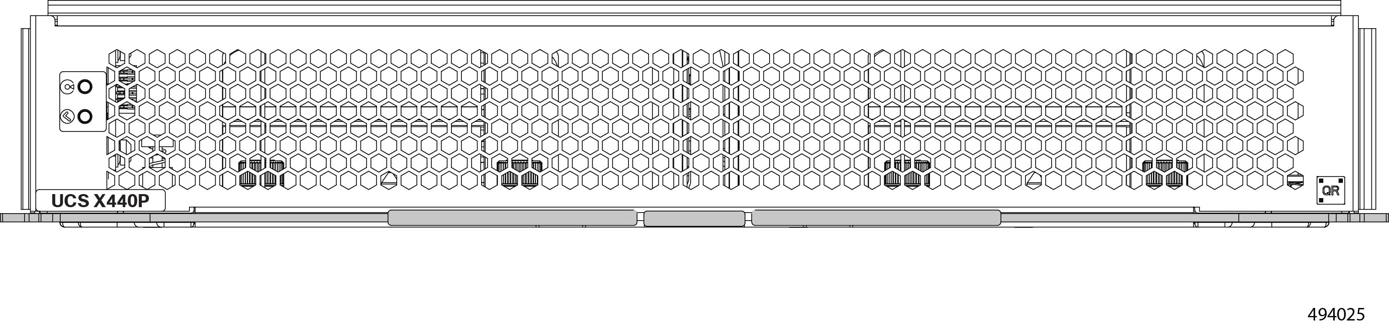
With the Cisco UCS X440p PCIe Node, an M7 generation compute node is paired 1:1.
-
With the Cisco UCS X580p PCIe node, up to two M8 generation compute nodes can be paired with each PCIe node.
-
-
Two Intelligent Fabric Modules (IFMs) and two Cisco X9416 X-Fabric Modules (XFMs) or Cisco X9516 X-Fabric Modules are required in each UCS X9508 chassis for full performance.
Either servers or compute nodes, and PCIe nodes are managed through the GUI or API with Cisco Intersight.
The Cisco UCS X9508 Server Chassis system consists of the following components:
-
Chassis versions:
-
Cisco UCS X9508 server chassis–AC version
-
-
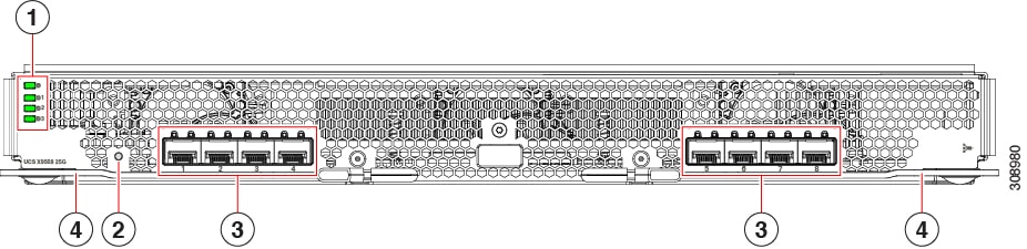
Intelligent Fabric Modules (IFMs), two deployed as a pair:
-
Cisco UCS 9108 100G IFMs (UCSX-I-9108-100G)—Two I/O modules, each with 8 100 Gigabit QSFP28 optical ports
-
Cisco UCS 9108 25G IFMs (UCSX-I-9108-25G)—Two I/O modules, each with 8 25 Gigabit SFP28 optical ports
-
-
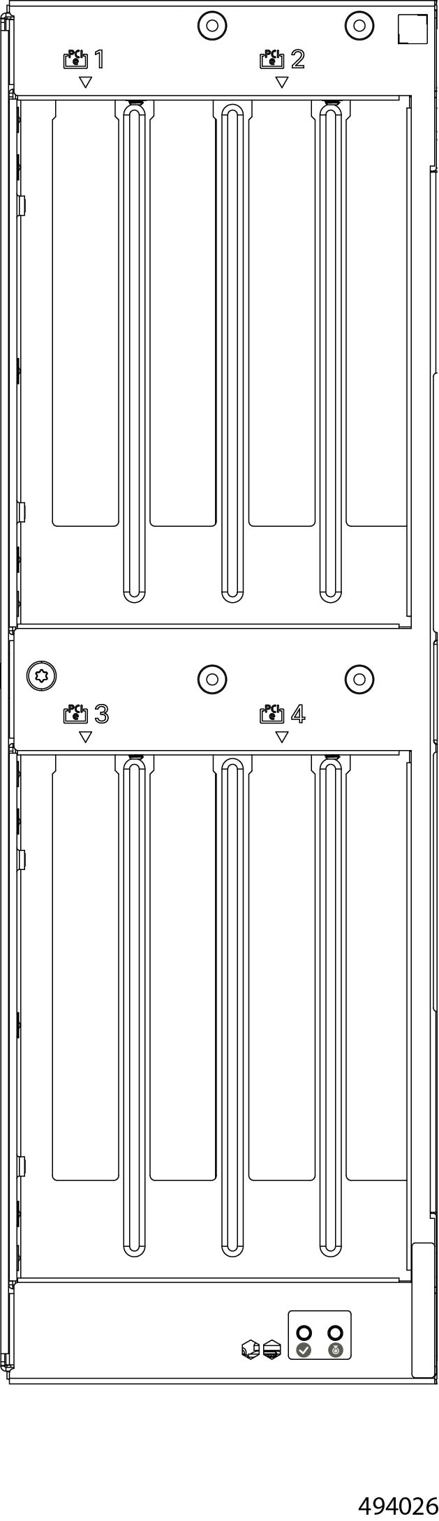
X-Fabric Modules:
-
Two UCS X9416 XFMs are required in each UCS X9508 server chassis to support GPU acceleration through Cisco UCS X440p PCIe nodes.
-
Two UCS X9516 XFMs are required in each UCS X9508 server chassis to support GPU acceleration through Cisco UCS X580p PCIe nodes.
-
-
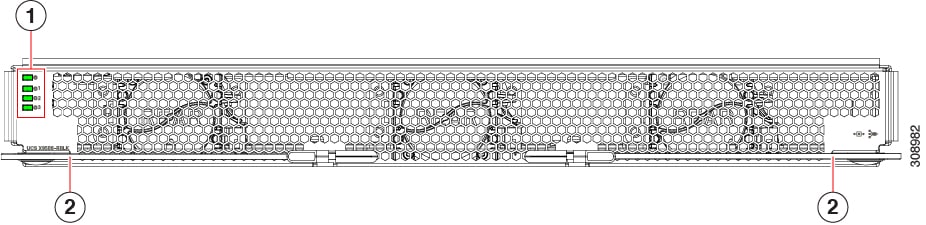
Power supplies—Up to six 2800 Watt, hot-swappable power supplies
-
Fan modules—Four hot-swappable fan modules
-
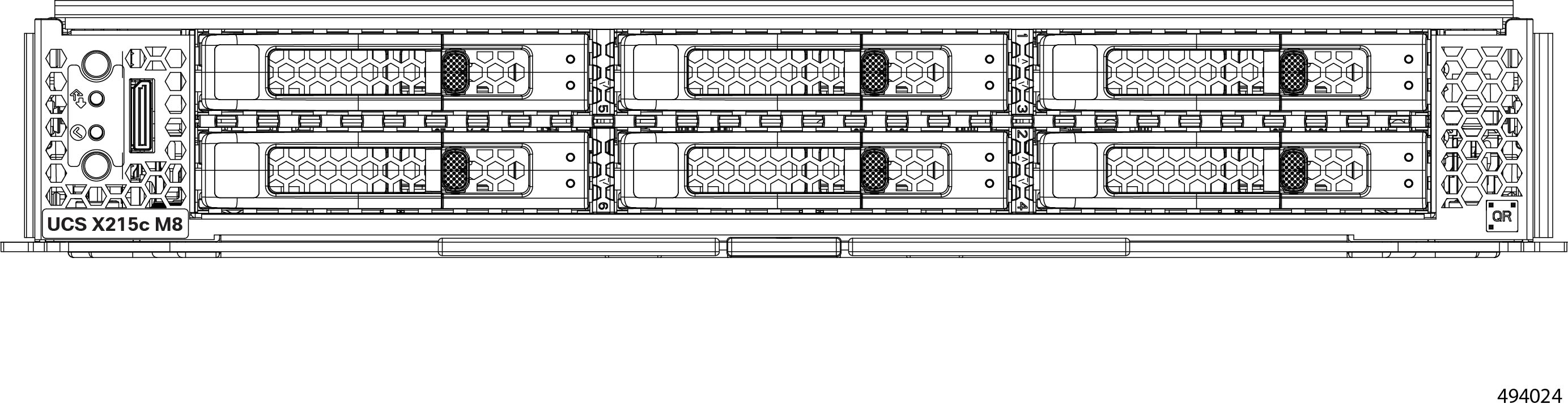
Up to 8 UCS X Series compute nodes of M6 or M7 generation for PCIe Gen4 connectivity through the X9416 XFMs, or up to 8 UCS X series compute nodes of M8 generation for PCIe Gen5 connectivity through the UCS X516 XFMs.
-
Up to 4 UCS X-Series M6 or M7 compute nodes paired 1:1 with up to 4 Cisco UCS X440p PCIe Nodes and two UCS X9416 XFMs for PCIe Gen4 connectivity.
-
Up to 4 UCS X-Series M8 compute nodes paired with up to 2 Cisco UCS X580p PCIe Nodes and two UCS X516 XFMs for PCIe Gen5 connectivity.
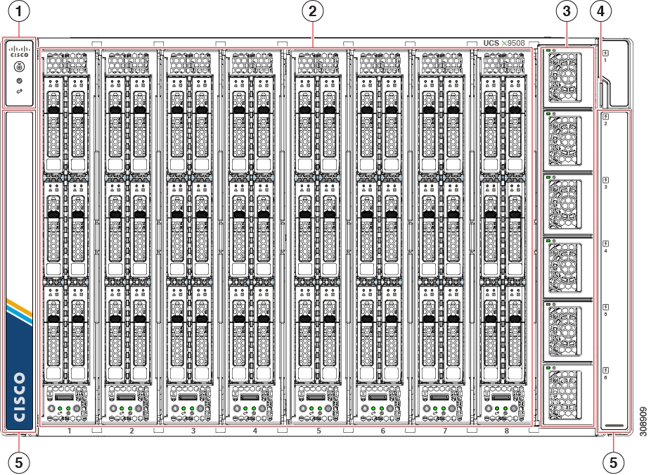
|
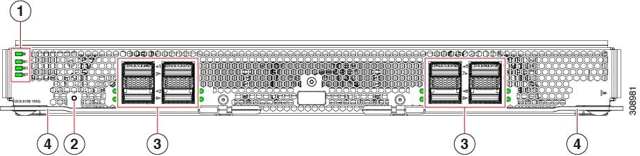
1 |
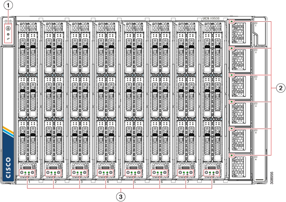
System LEDs:
For information about System LEDs, see LEDs. |
2 |
Node Slots, a total of 8. Shown populated with compute nodes, but can also contain PCIe Nodes |
|
3 |
Power Supplies, a maximum of 6. |
4 |
System Asset Tag |
|
5 |
System side panels (two), which are removable. The side panels cover the rack mounting brackets. |
|
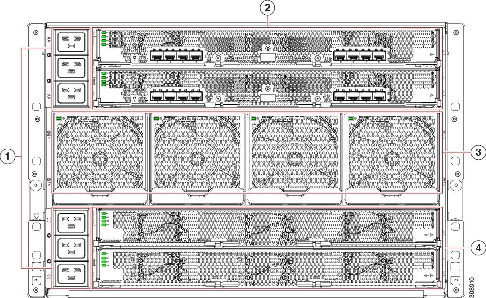
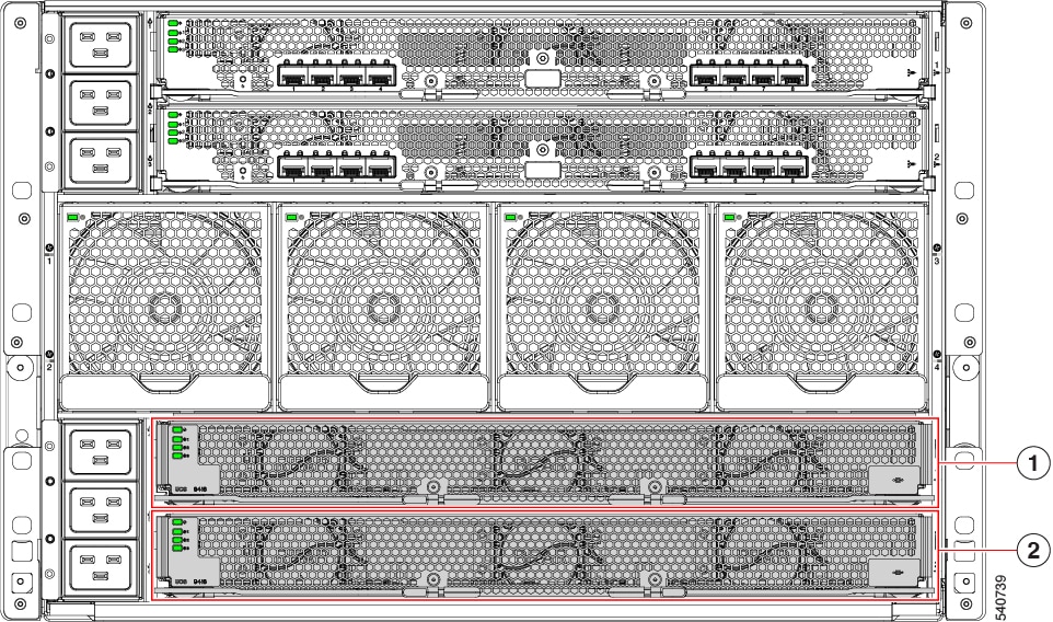
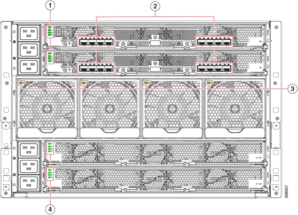
1 |
Power Entry Modules (PEMs) for facility inlet power Each PEM contains 3 IEC 320 C20 inlets.
|
2 |
Intelligent Fabric Modules (shown populated), which are always deployed as a pair of the following:
|
|
3 |
System fans (four) |
4 |
X-Fabric Module slots for either UCS active filler panels (for compute nodes) or up to two UCS X-Fabric Modules (for compute nodes paired with PCIe nodes). |


 Feedback