Components
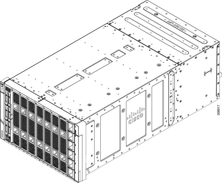
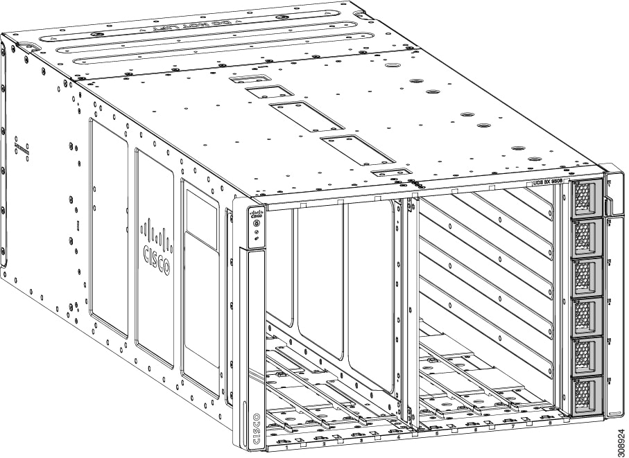
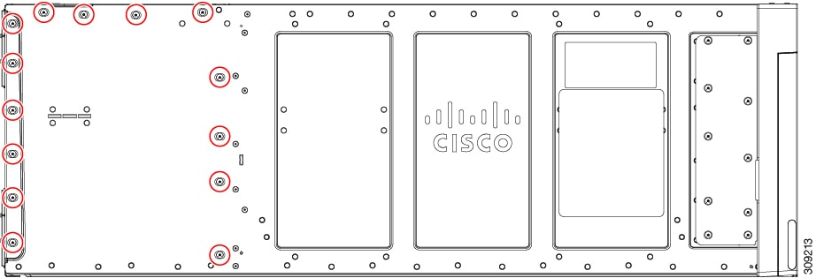
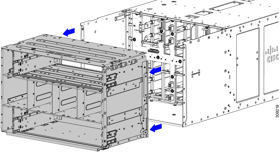
The following figure shows an empty Cisco UCS X9508 server chassis and identifies the front, back, and vertical node slots, and horizontal module slots.
 Note |
Before you remove or install components, please ensure that all software applications are shut down and management software is in a good state. |
Note |
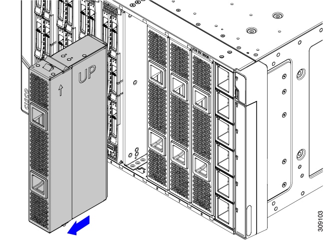
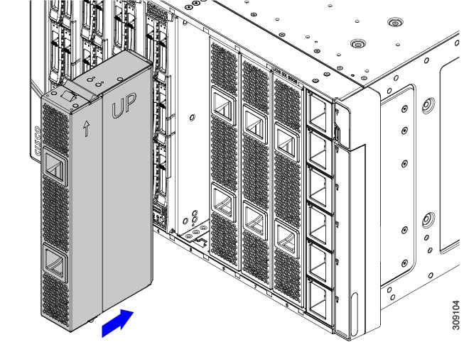
Whenever you remove a module from the chassis for an extended period of time, always replace the module with the appropriate blank panel. Failing to do so can result in heating and EMI issues. Blank panels can be ordered from Cisco Systems. |
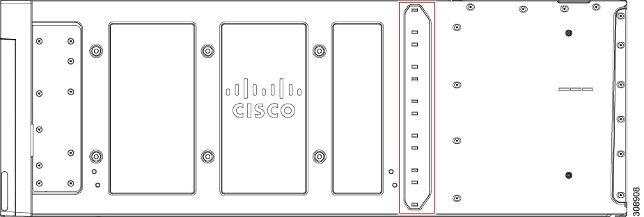
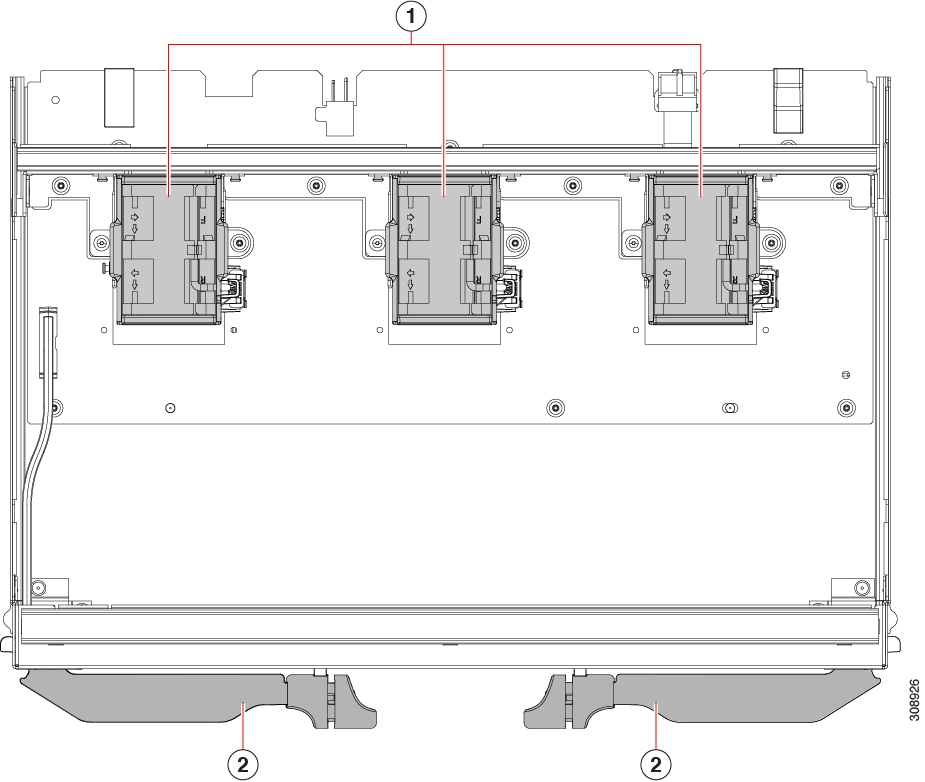
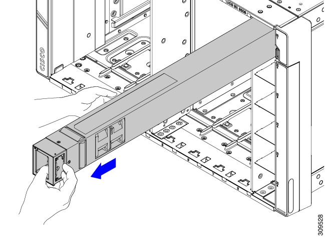
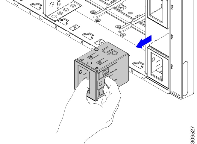
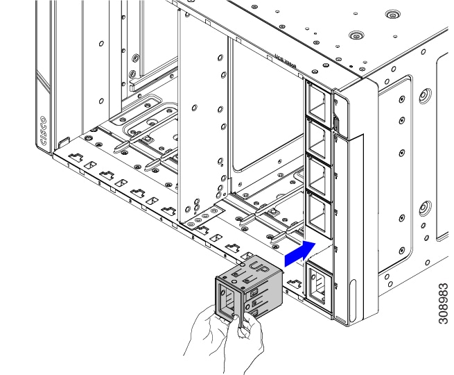
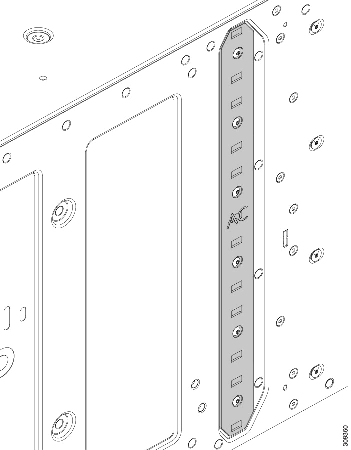
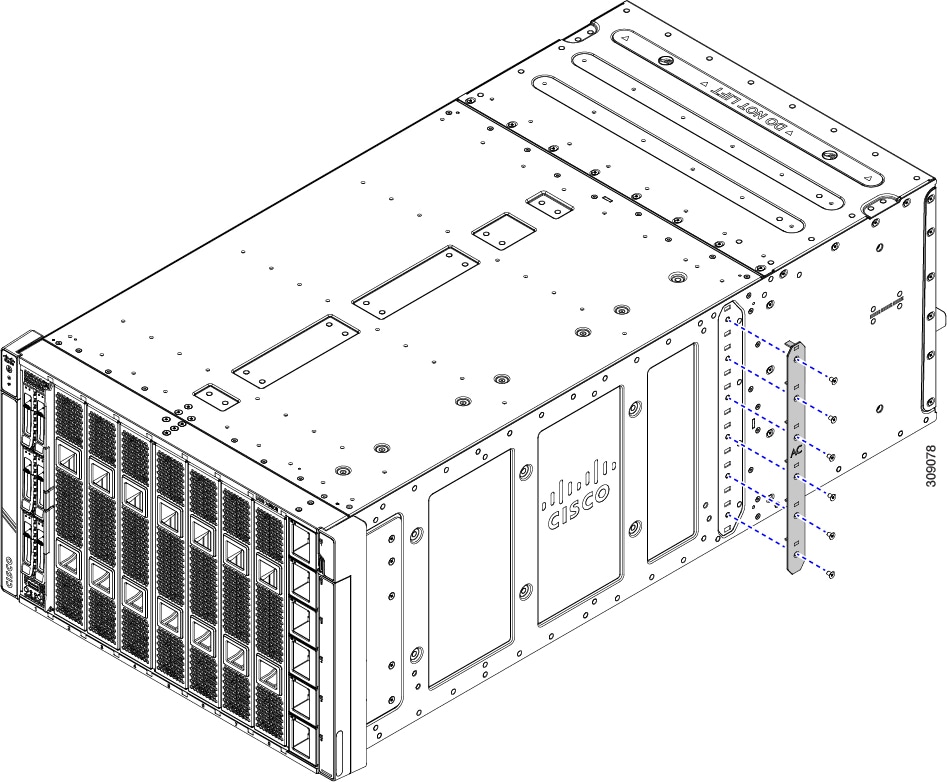
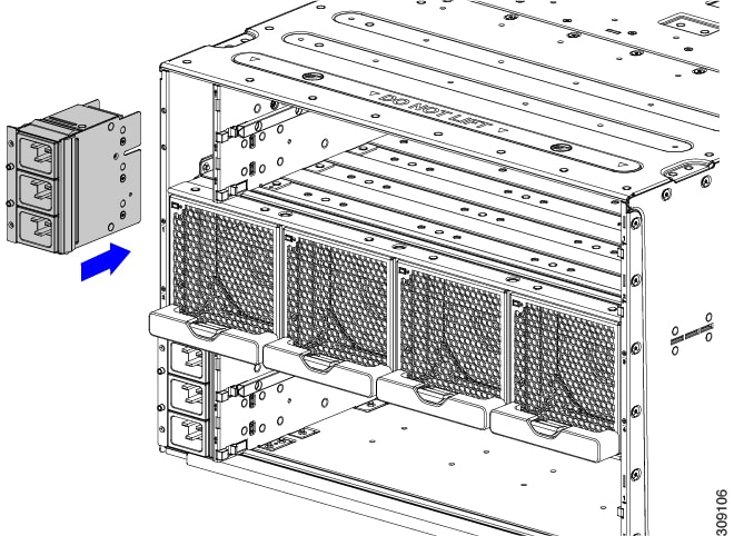
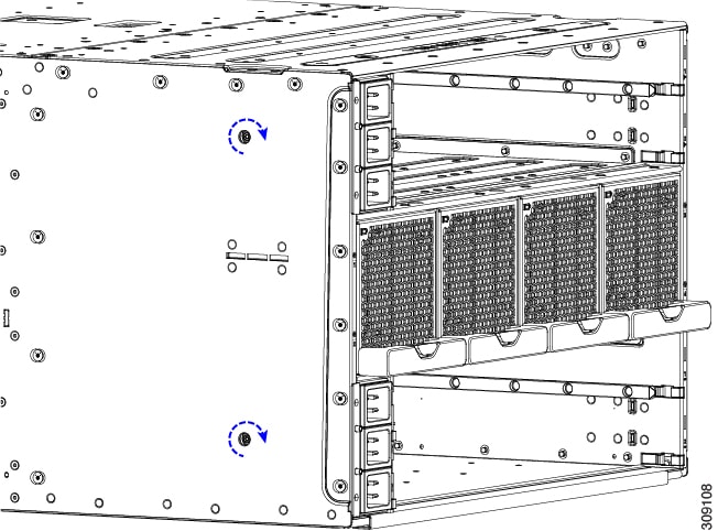
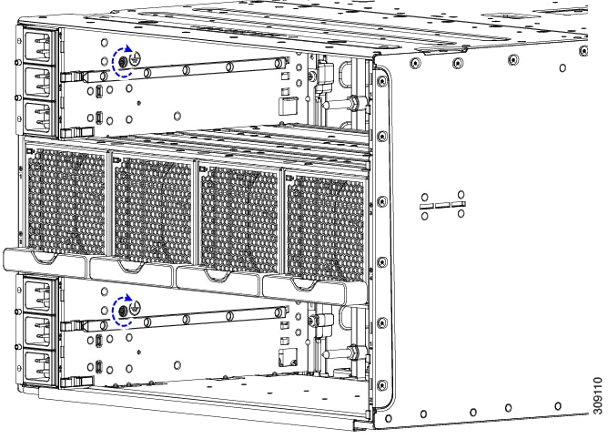
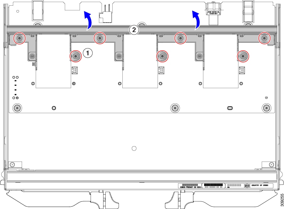
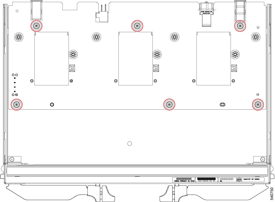
The side of the chassis has no handles because the chassis is heavy, and not intended to be lifted unless you are using a scissor lift or another type of mechanical lift device to bear the weight of the chassis. The right side of the chassis has the PSU Keying Bracket which enforces proper PSU orientation as well as proper PSU type.
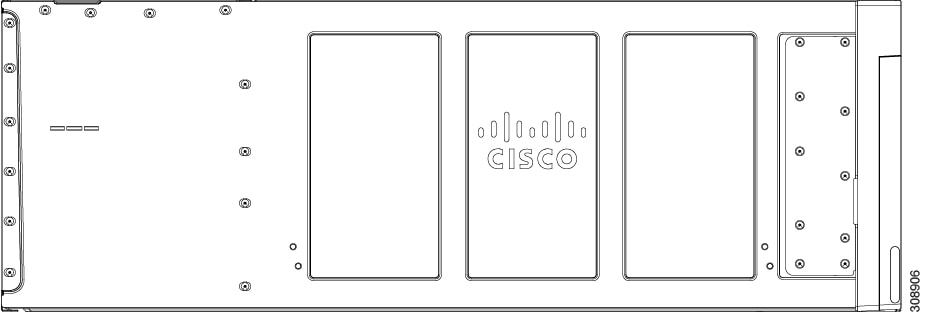
The left side of the chassis has no handles.
|
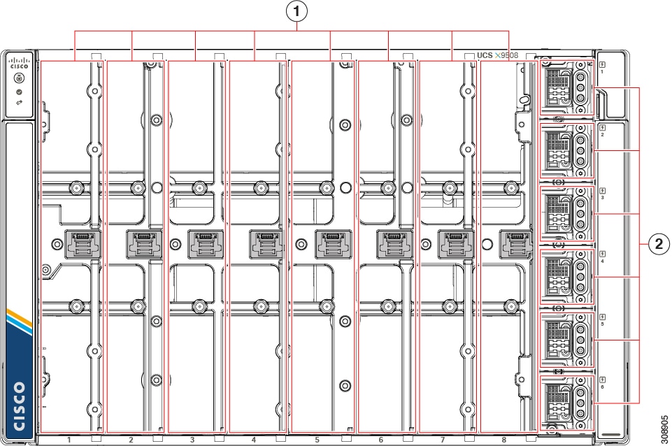
1 |
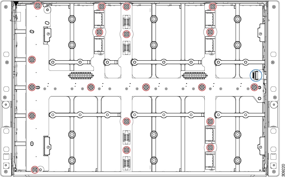
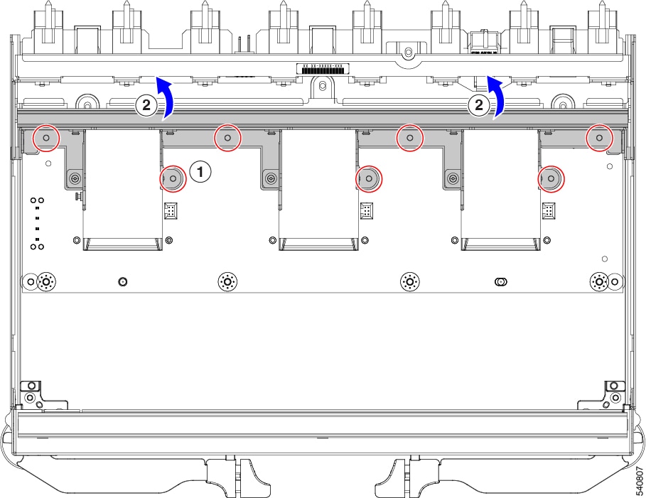
Node slots (8). Each slot is numbered horizontally below each slot. Compute nodes and PCIe nodes can be inserted vertically and connect to the power socket for each slot. |
2 |
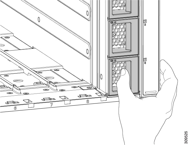
PSU bays (6). Each PSU bay is numbered vertically to the right of the bay. Each PSU bay is keyed so that the PSU inserts only one way. |
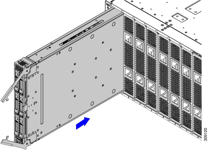
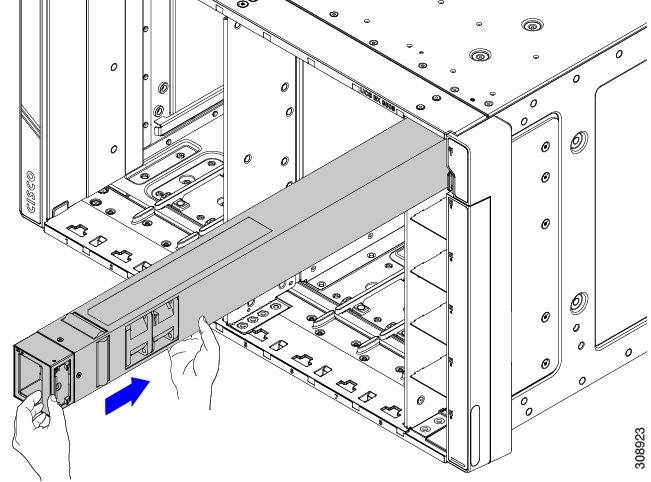
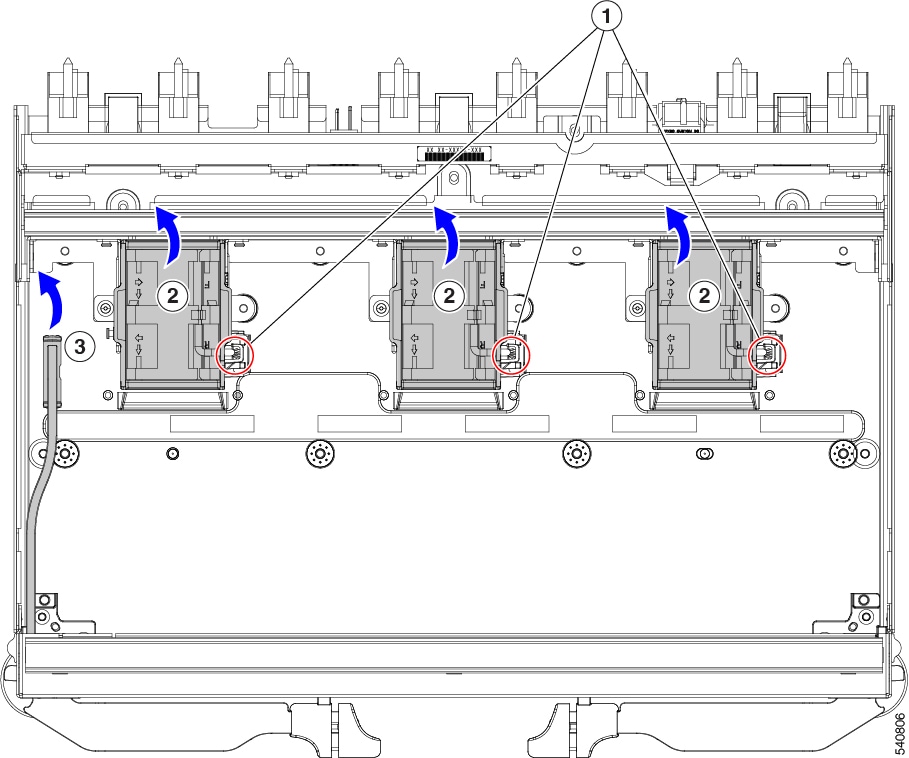
The front of the chassis accepts up to 8 single-slot or 4 dual-slot compute nodes with connections for power and basic signaling through the per-slot socket connections to the midplane. The front of the server chassis also hosts up to 6 PSUs providing power to the chassis power plane through internal connectors. PSUs are numbered one through six with PSU bay one as the topmost slot and PSU bay 6 on the bottom.
 Caution |
Any node slot that is not occupied must have a compute node blank panel (UCSX-9508-FSBK) installed. |
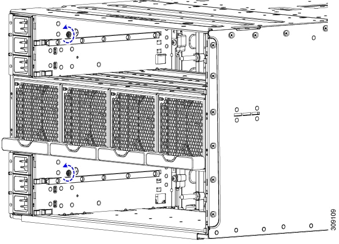
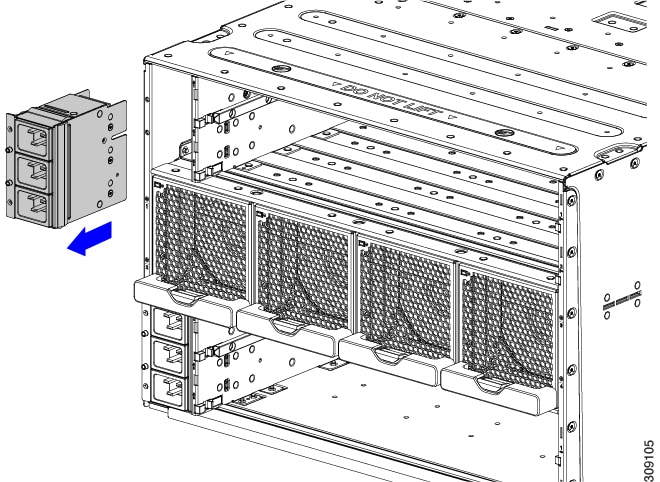
|
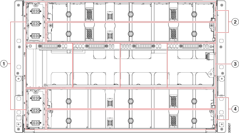
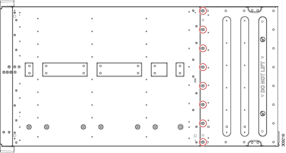
1 |
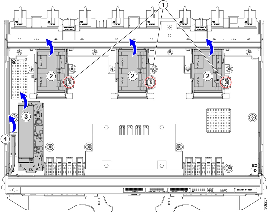
Power Entry Modules (2) Each PEM houses three IEC 320 compatible C20 power inlets inlet facility power. |
2 |
IFM slots (2) |
|
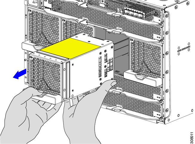
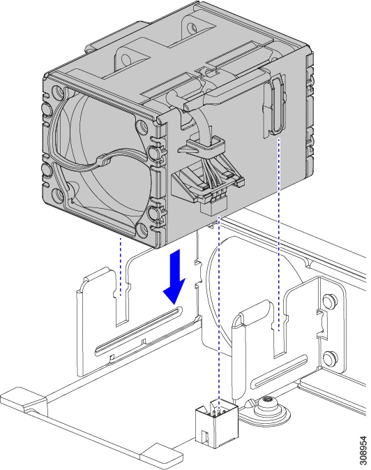
3 |
Fan Bays (4) Fans are numbered 1 through 4 with fan 1 as the leftmost. |
4 |
Expansion Slots (2) |
The top of the chassis rear contains up to two Intelligent Fabric Modules (IFMs). Power connections and minimal signaling are supported through the per-slot socket connections to the midplane. Three vertically stacked Power Entry Module (PEM) connectors are also supported, which correspond with PSUs one through three, with PSU one as the topmost connector.
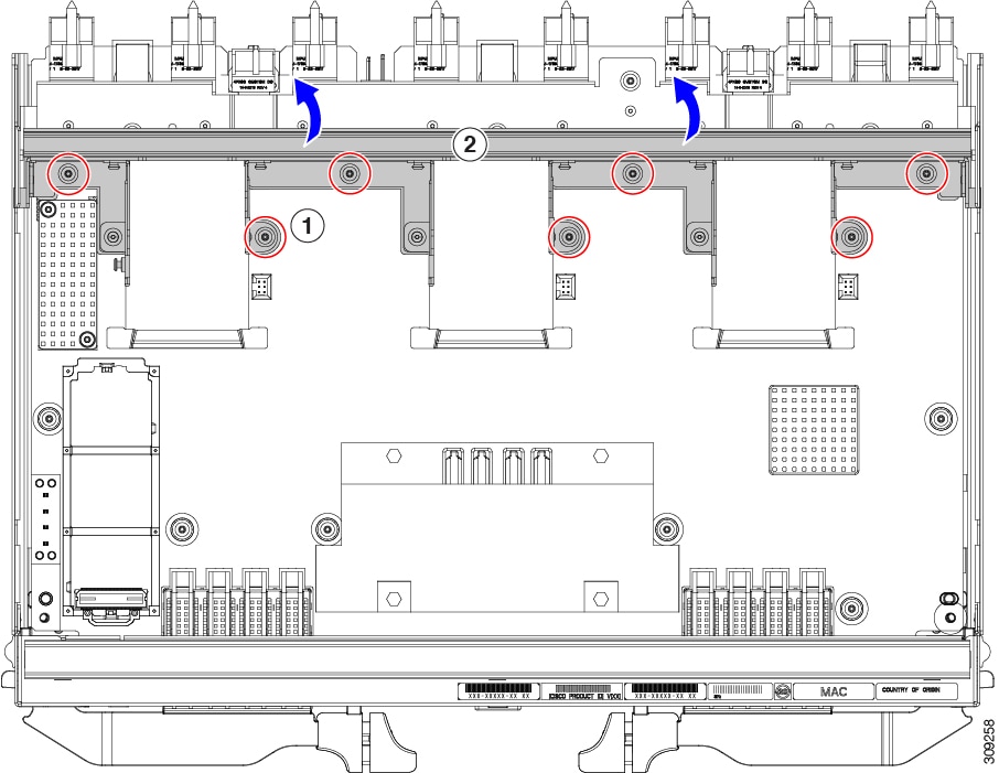
The middle of the chassis rear houses up to four fan modules and power is supplied through one connector per fan module. Fans are numbered from one to four with Fan 1 being the leftmost fan, and Fan 4 being the right most.
The bottom of the chassis rear houses two active fan modules. Power connections and minimal signaling are supported through the per-slot socket connections to the midplane. Three vertically stacked PEM connectors are also supported, which correspond with PSUs four through six, with PSU four as the topmost connector.
Note |
Before you install, operate, or service the system, see the Regulatory Compliance and Safety Information for Cisco UCS for important safety information. |
 Warning |
IMPORTANT SAFETY INSTRUCTIONS This warning symbol means danger. You are in a situation that could cause bodily injury. Before you work on any equipment, be aware of the hazards involved with electrical circuitry and be familiar with standard practices for preventing accidents. Use the statement number provided at the end of each warning to locate its translation in the translated safety warnings that accompanied this device. Statement 1071 SAVE THESE INSTRUCTIONS |
Warning |
This unit is intended for installation in restricted access areas. A restricted access area can be accessed only through the use of a special tool, lock and key, or other means of security. Statement 1017 |
Warning |
Only trained and qualified personnel must be allowed to install, replace, or service this equipment. Statement 1030 |
Cisco UCS 9108 25G IFM Components
The Cisco UCS 9108 25G Intelligent Fabric Module has the following board-level components.
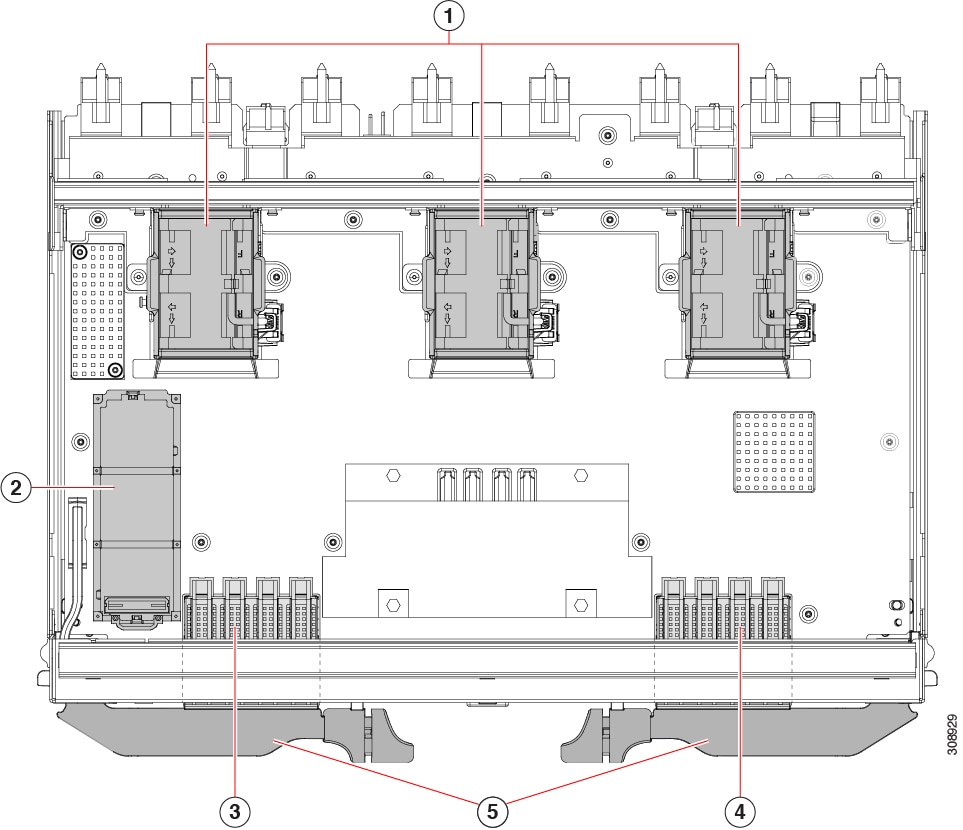
|
1 |
Fans (UCSX-RSFAN=), three, which are numbered 1 through 3 starting with the left fan. |
2 |
One M.2 mini storage module slot |
|
3 |
SFP28 Optical Ports. Ports are arranged in two groups of four physical ports. Port number 1 is the left port in this group, and port number 4 is the right port in the group. |
4 |
SFP28 Optical Ports. Ports are arranged in two groups of four physical ports. Port number 5 is the left port in this group, and port number 8 is the right port in the group. |
|
5 |
IFM ejector handles, left and right |
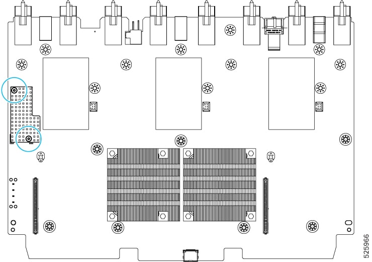
Cisco UCS 9108 100G IFM Components
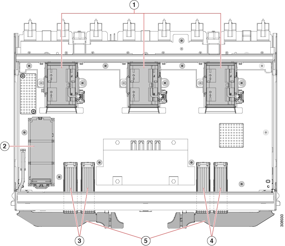
|
1 |
Fans, (UCSX-RSFAN=), three, which are numbered 1 through 3 starting with the left fan |
2 |
One M.2 mini storage module slot |
|
3 |
QSFP28 Optical Ports. Ports are arranged in two groups of four physical ports. Ports are stacked in vertical pairs, with two ports in each vertical port stack. Port number 1 is the top port of the left port pair in this group, and port number 3 is the top port of the right port pair in the group. |
4 |
QSFP28 Optical Ports. Ports are arranged in two groups of four physical ports. Ports are stacked in vertical pairs, with two ports in each vertical port stack. Port number 5 is the top port in the left port pair of this group, and port number 7 is the top port in the right port pair of the group. |
|
5 |
IFM ejector handles, left and right |
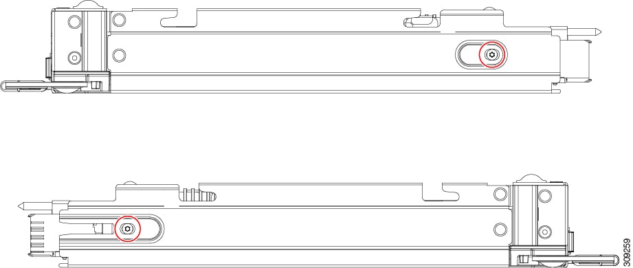
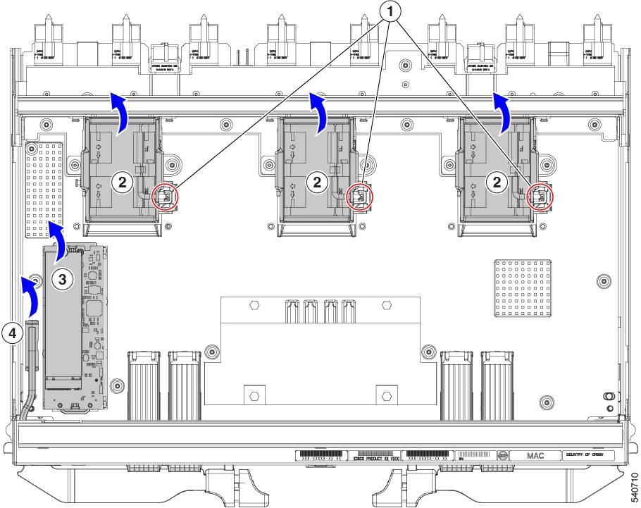
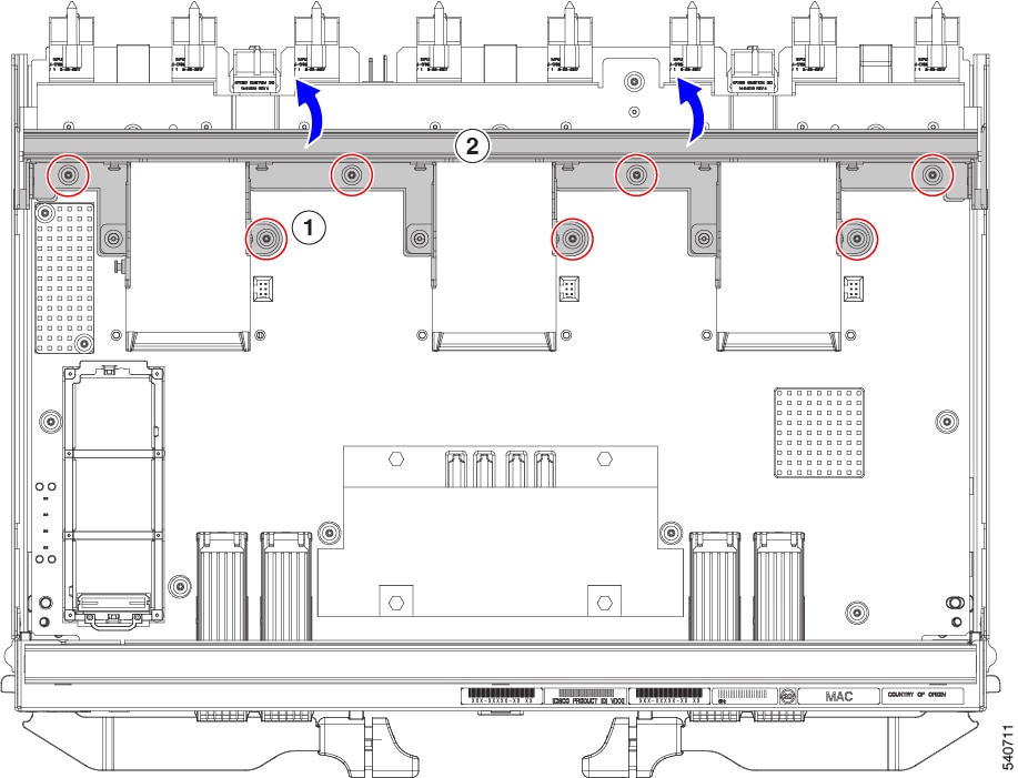
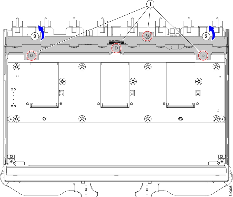
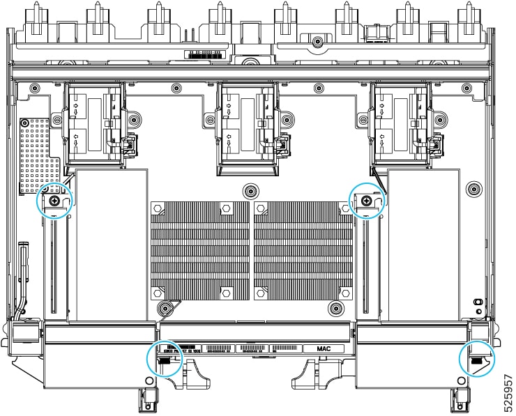
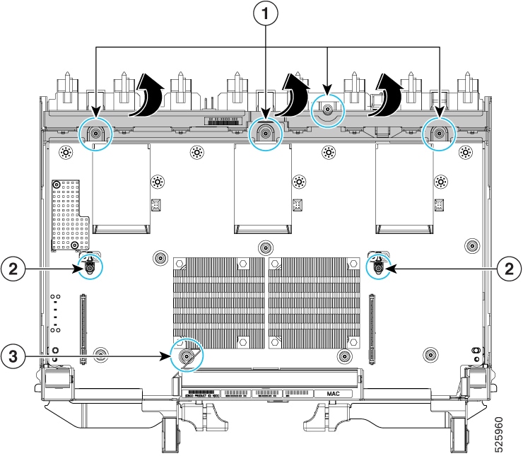
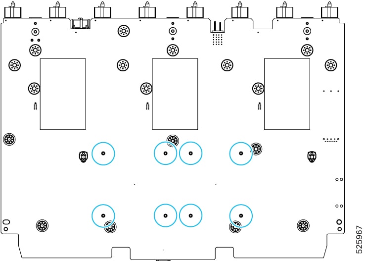
Cisco UCS X9416 Fabric Module Components
The Cisco X9416 module (UCSX-F-9416) has the following components.
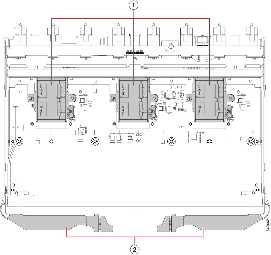
|
1 |
Fans (UCSX-RSFAN=), three, which are numbered 1 through 3 starting with the left fan |
2 |
Module Ejector Handles, Left and Right |
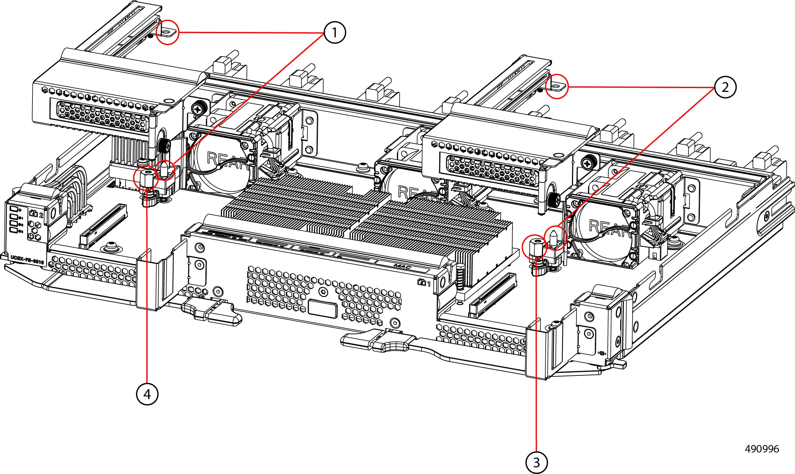
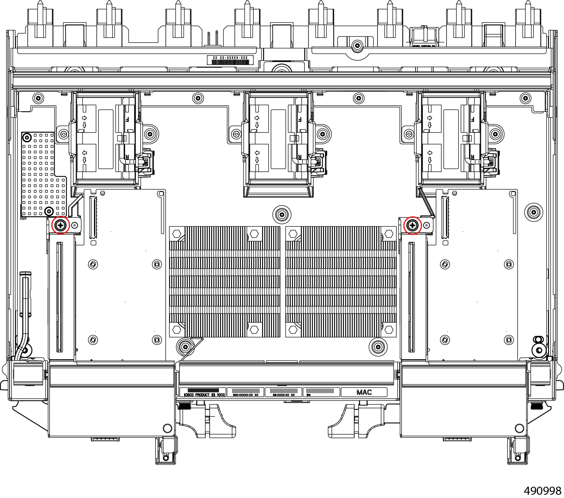
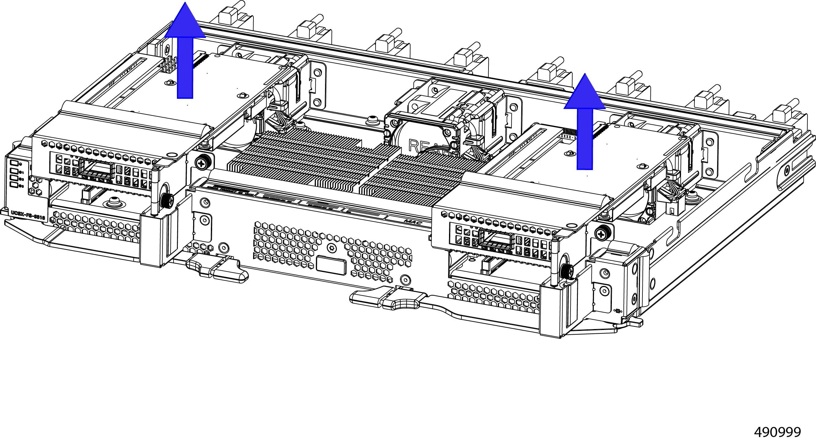
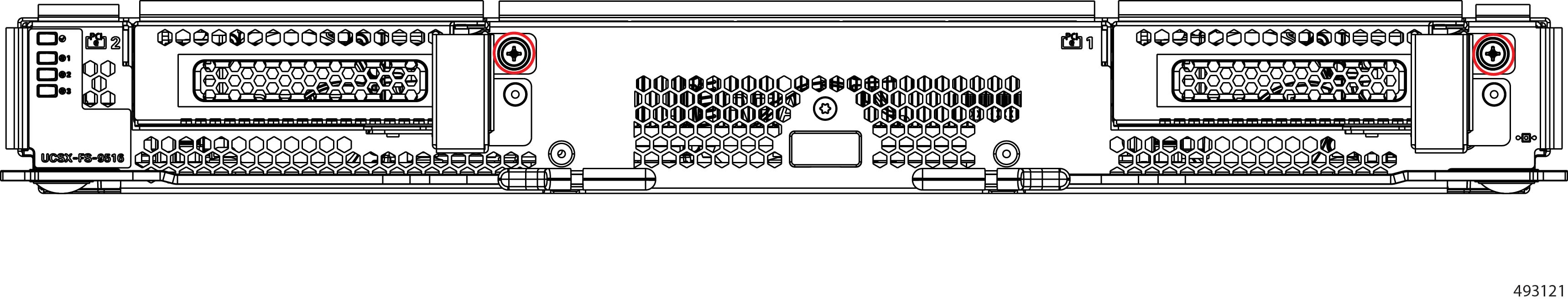
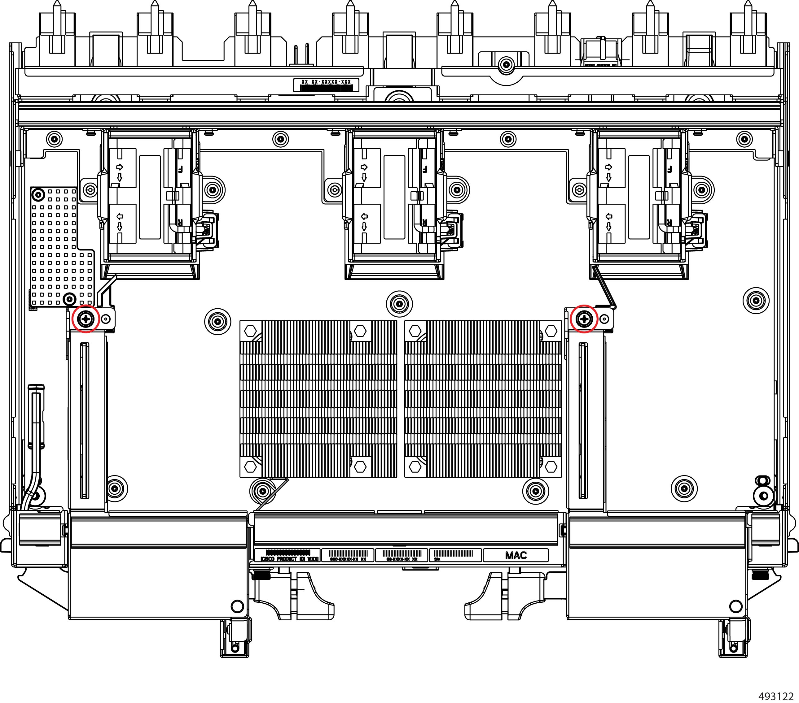
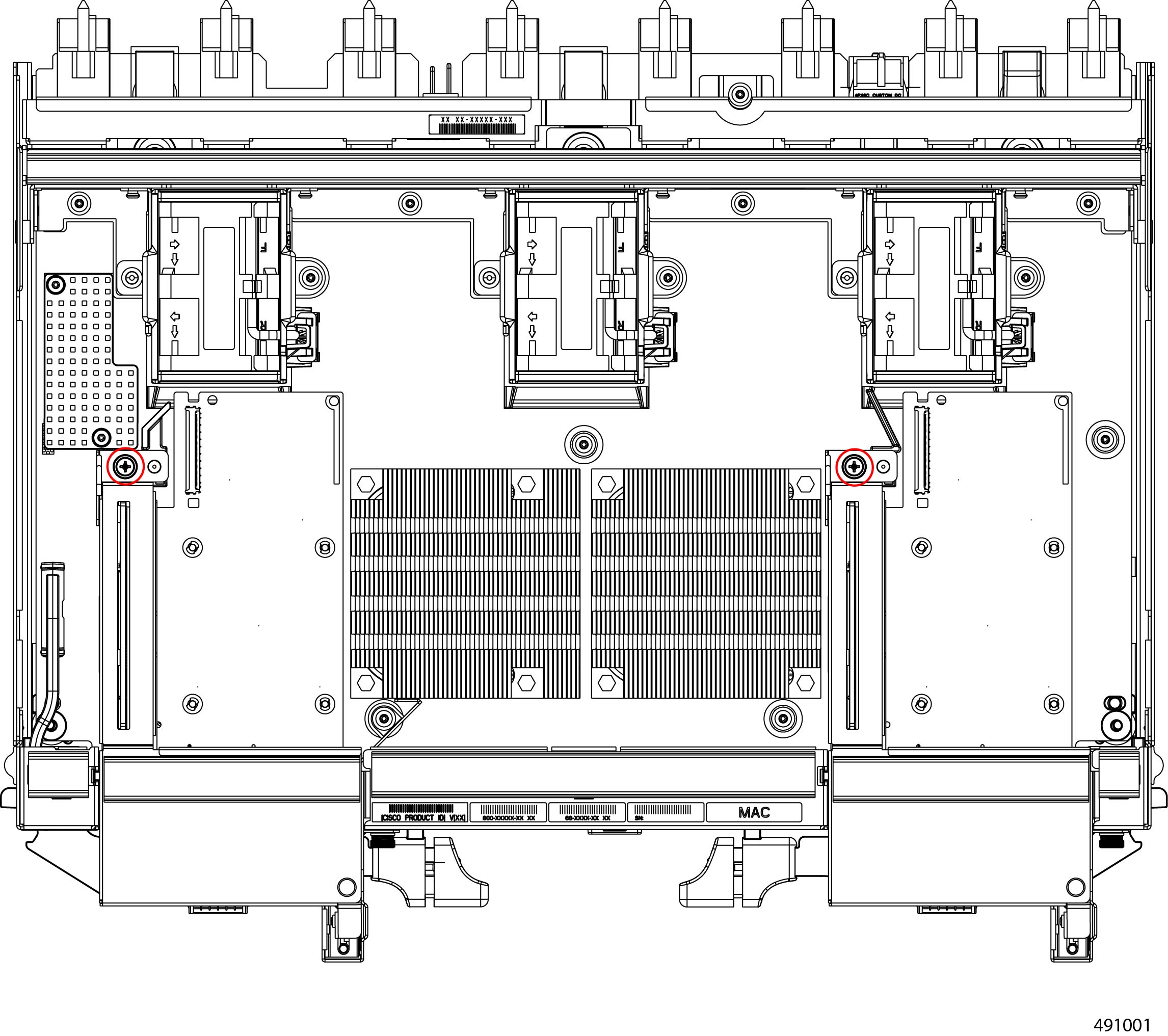
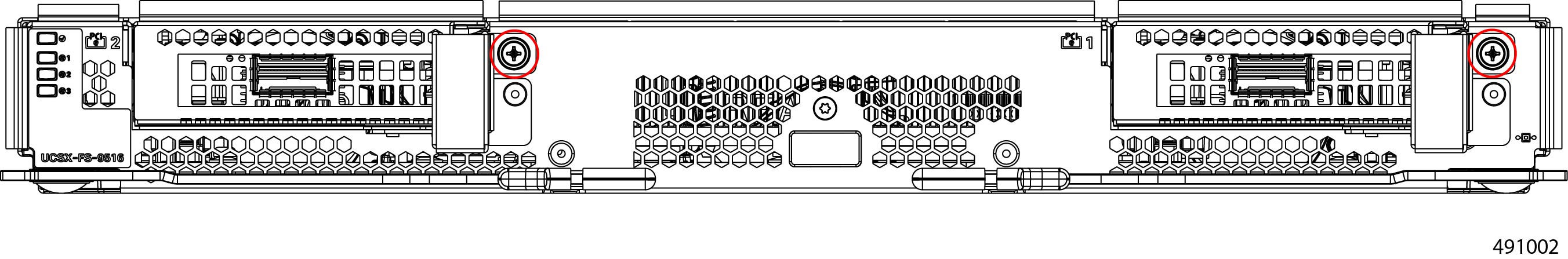
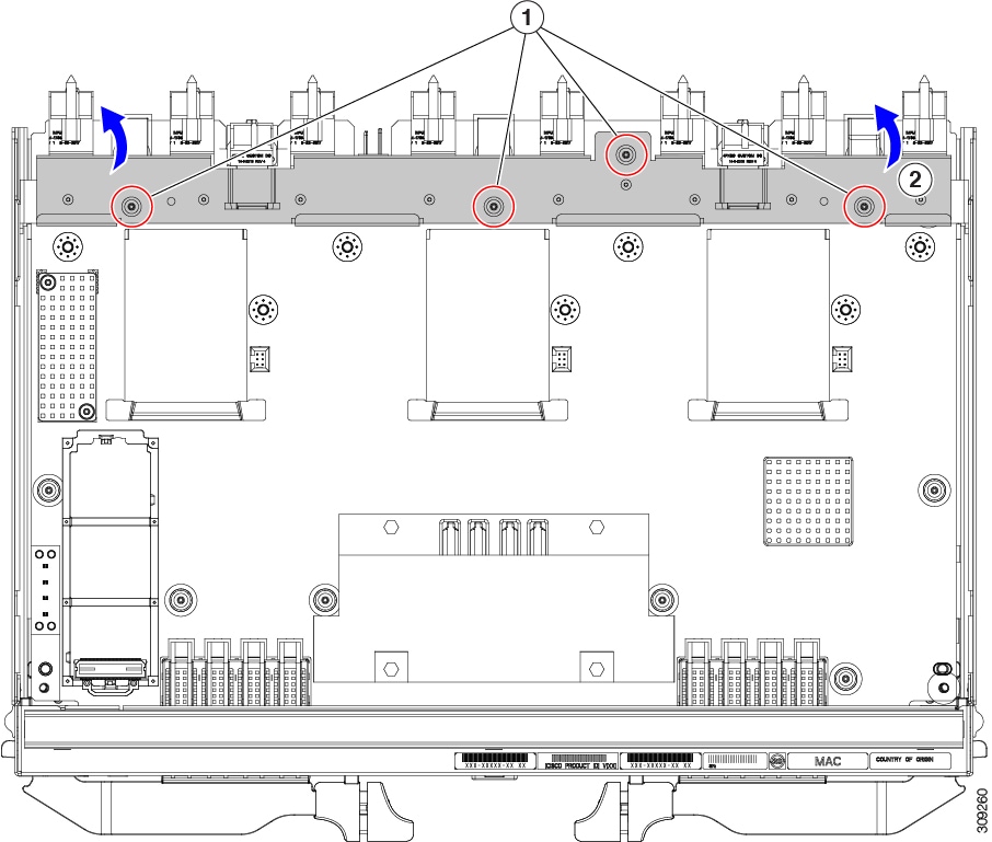
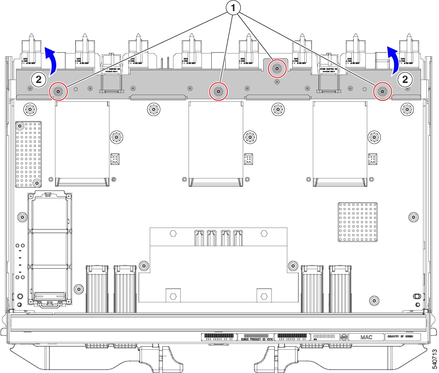
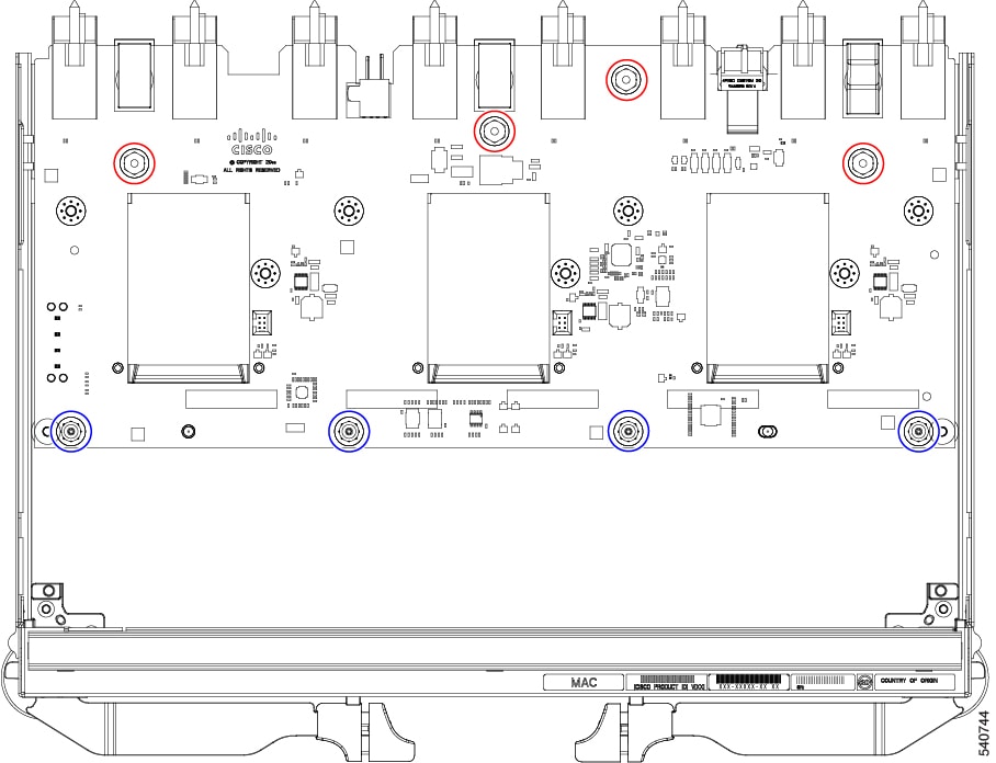
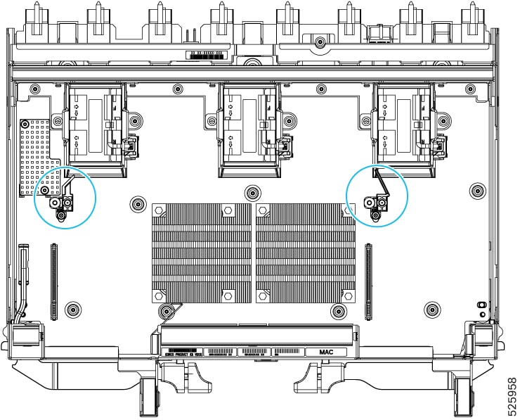
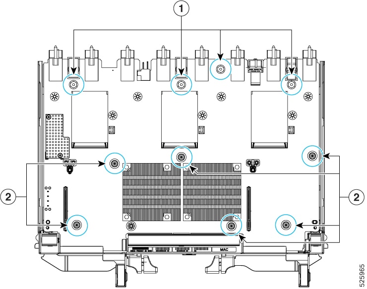
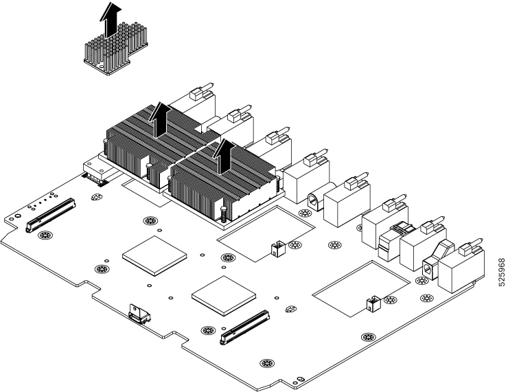
Cisco UCS X9516 Fabric Module Components
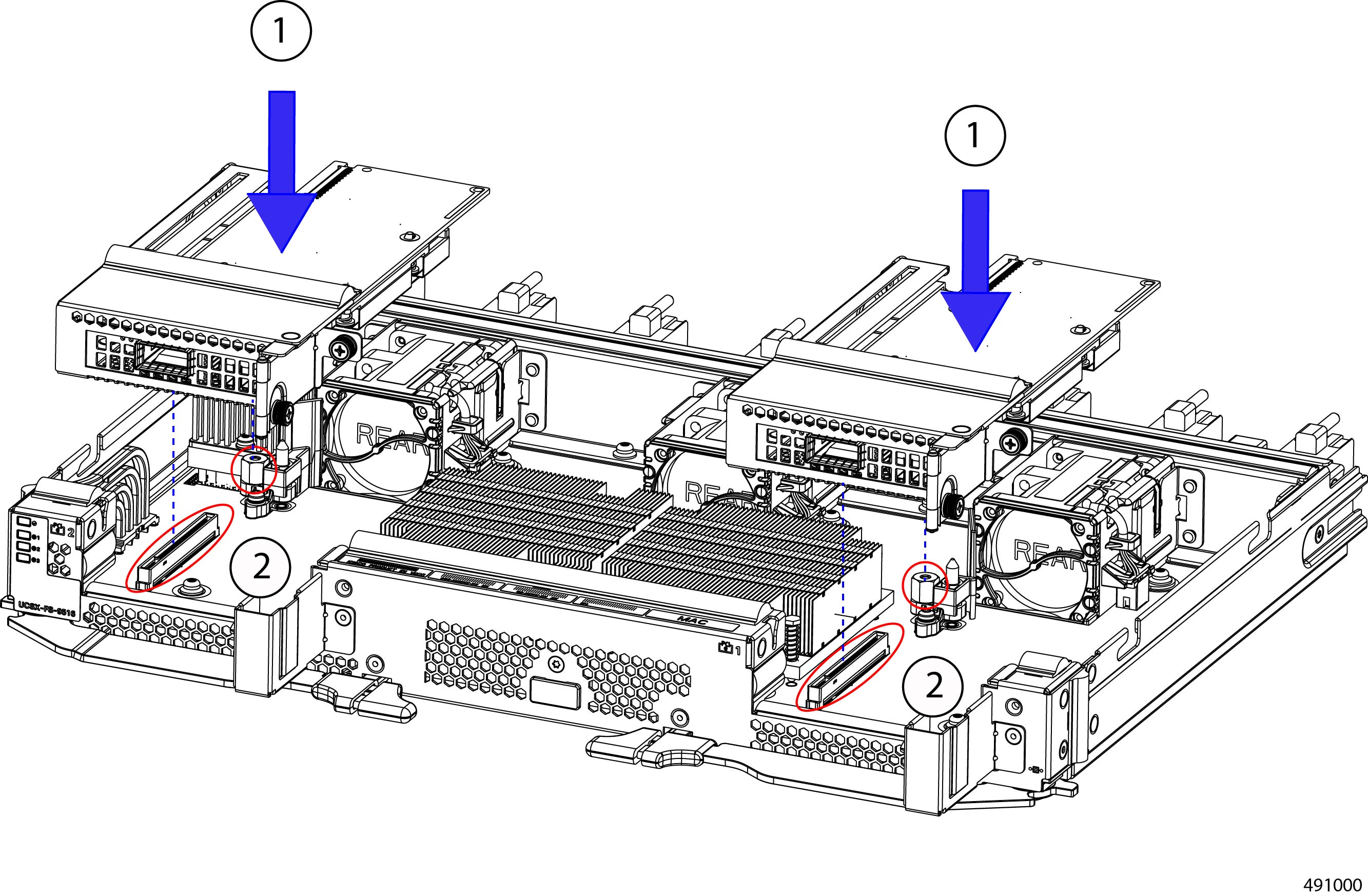
The Cisco UCS X9516 module (UCSX-FS-9516) X-Fabric Module has the following components.
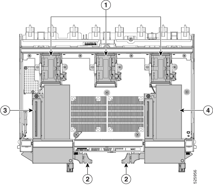
Note |
The module has multiple heatsinks, but they are not field-serviceable. |
|
1 |
Fans (UCSX-RSFAN=), three, which are numbered 1 through 3 starting with the left fan |
2 |
Module Ejector Handles, Left and Right |
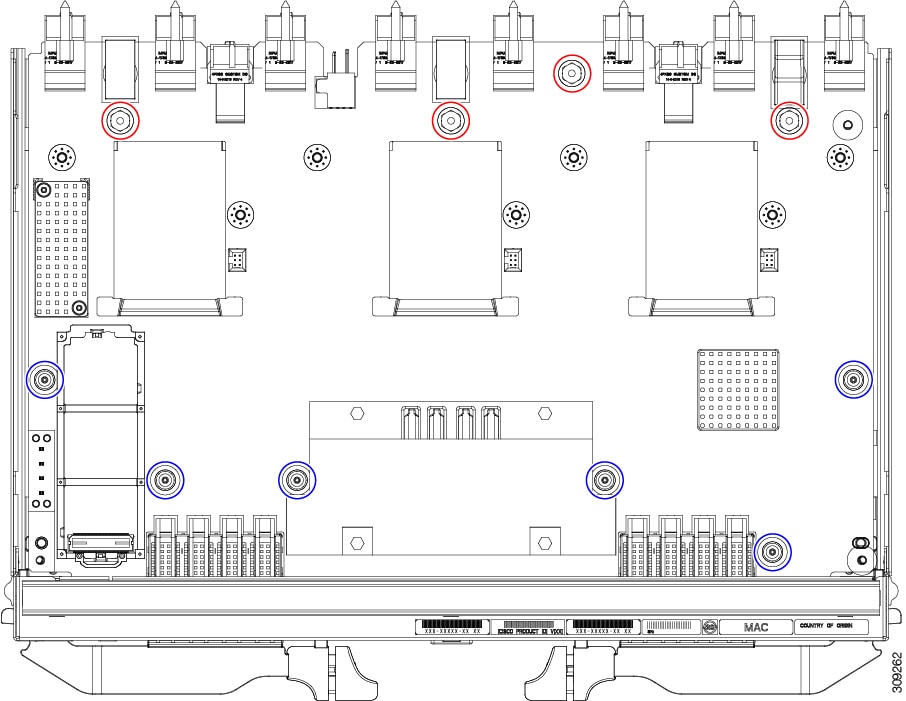
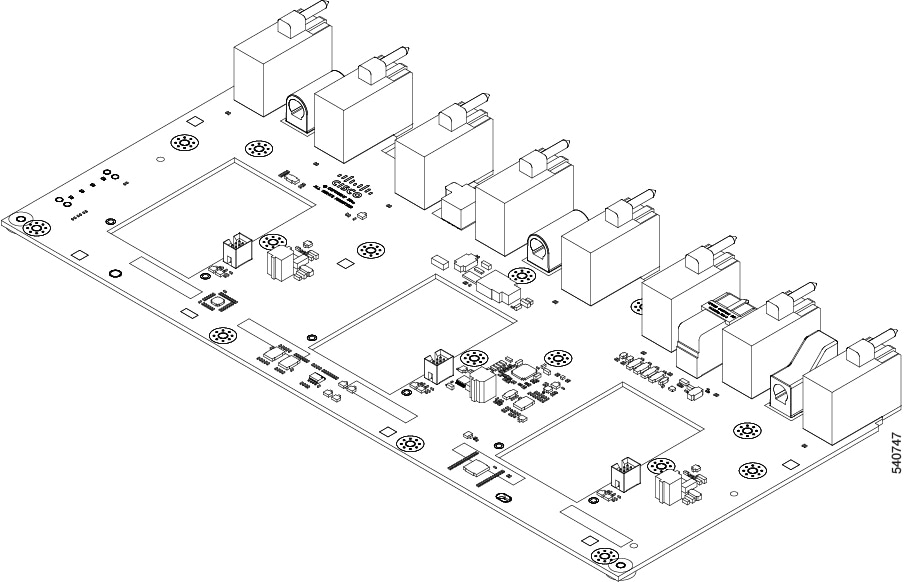
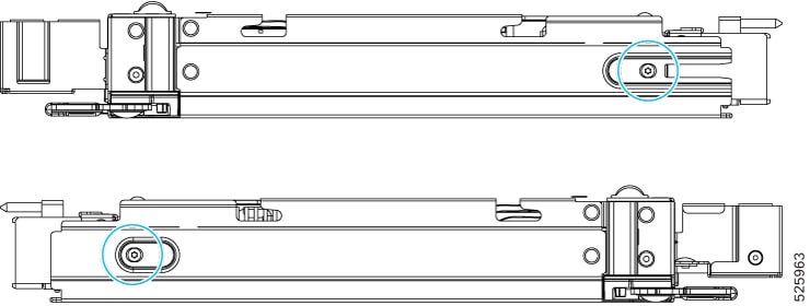
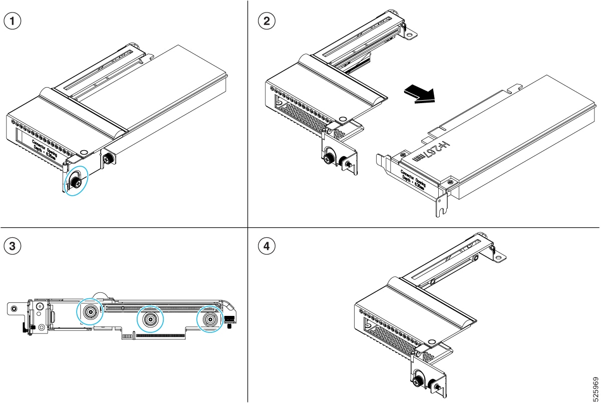
||||
|
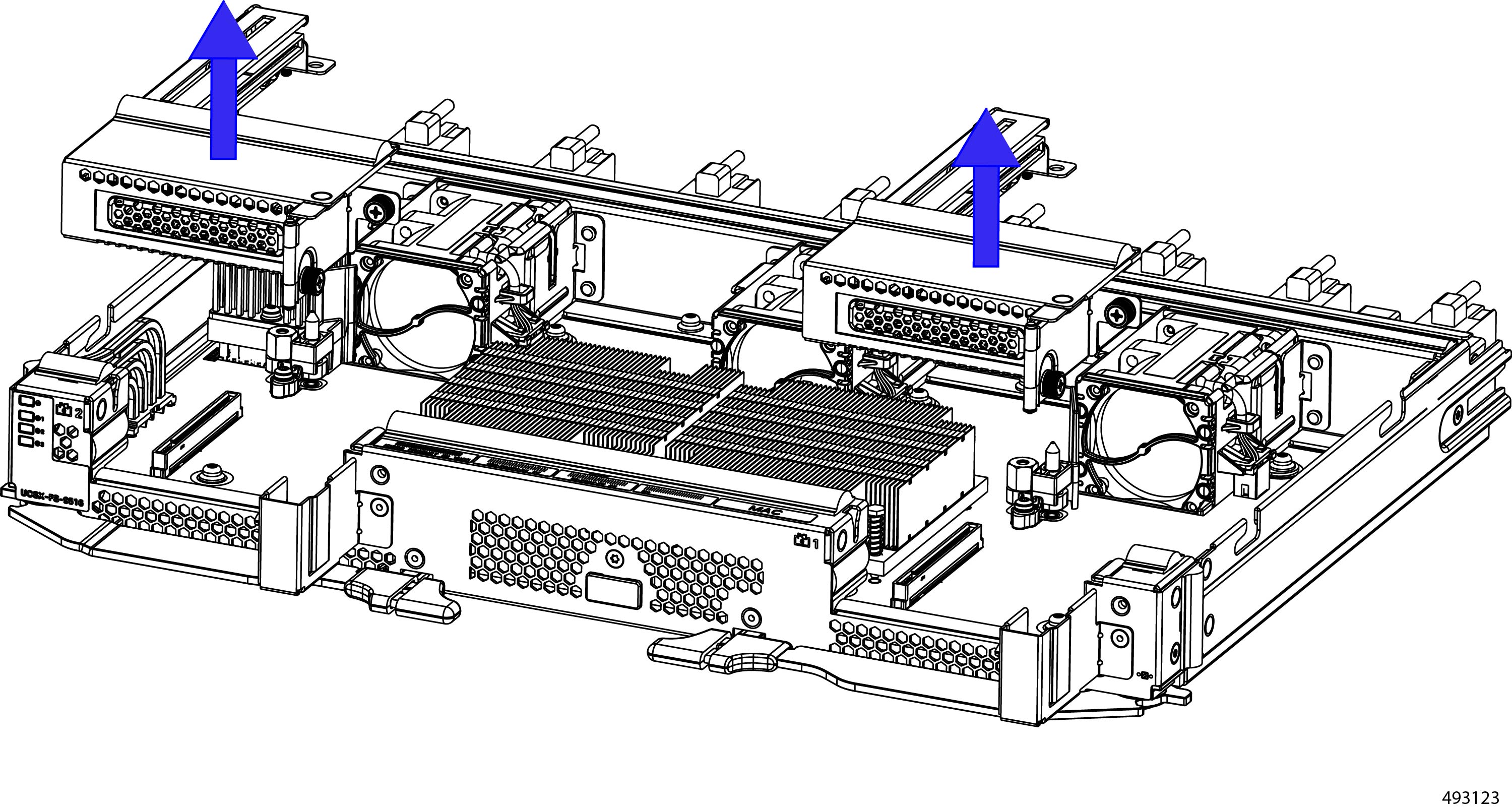
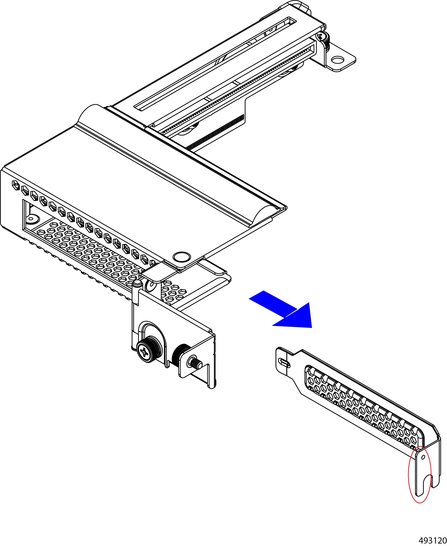
3 |
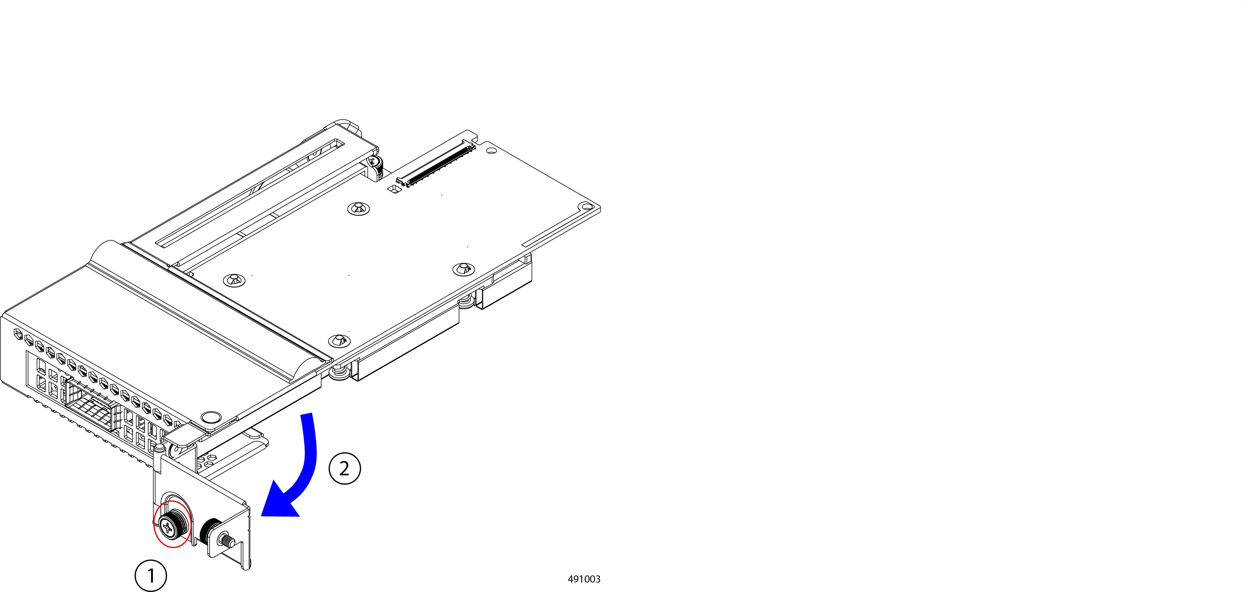
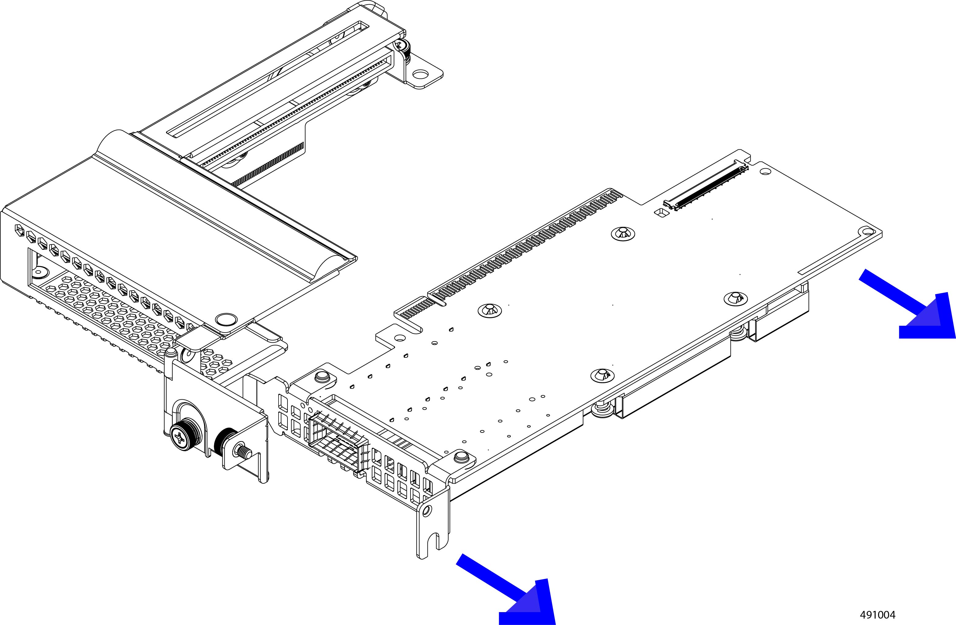
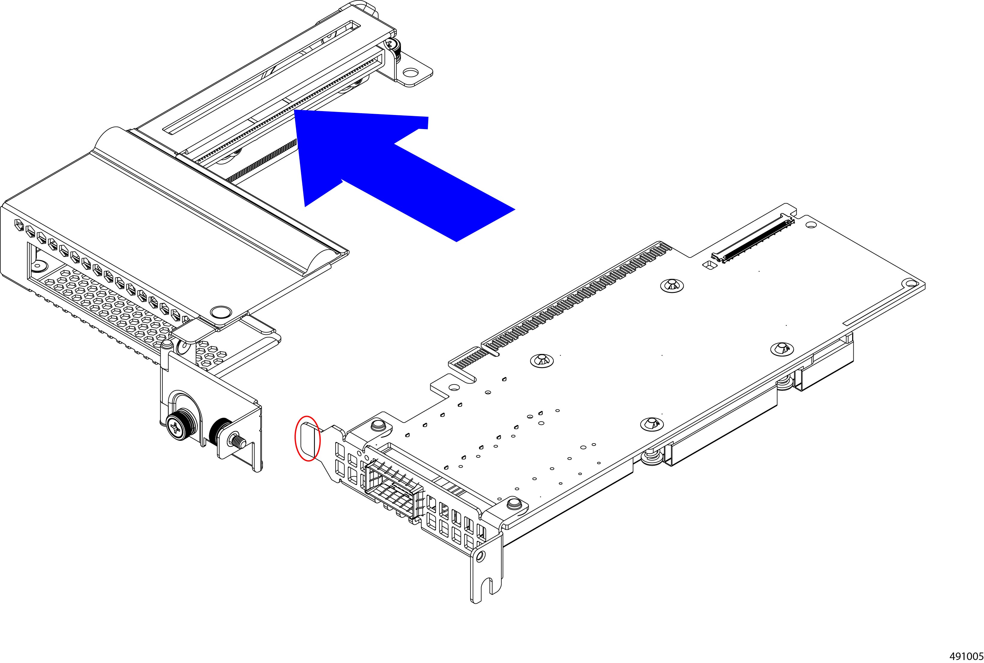
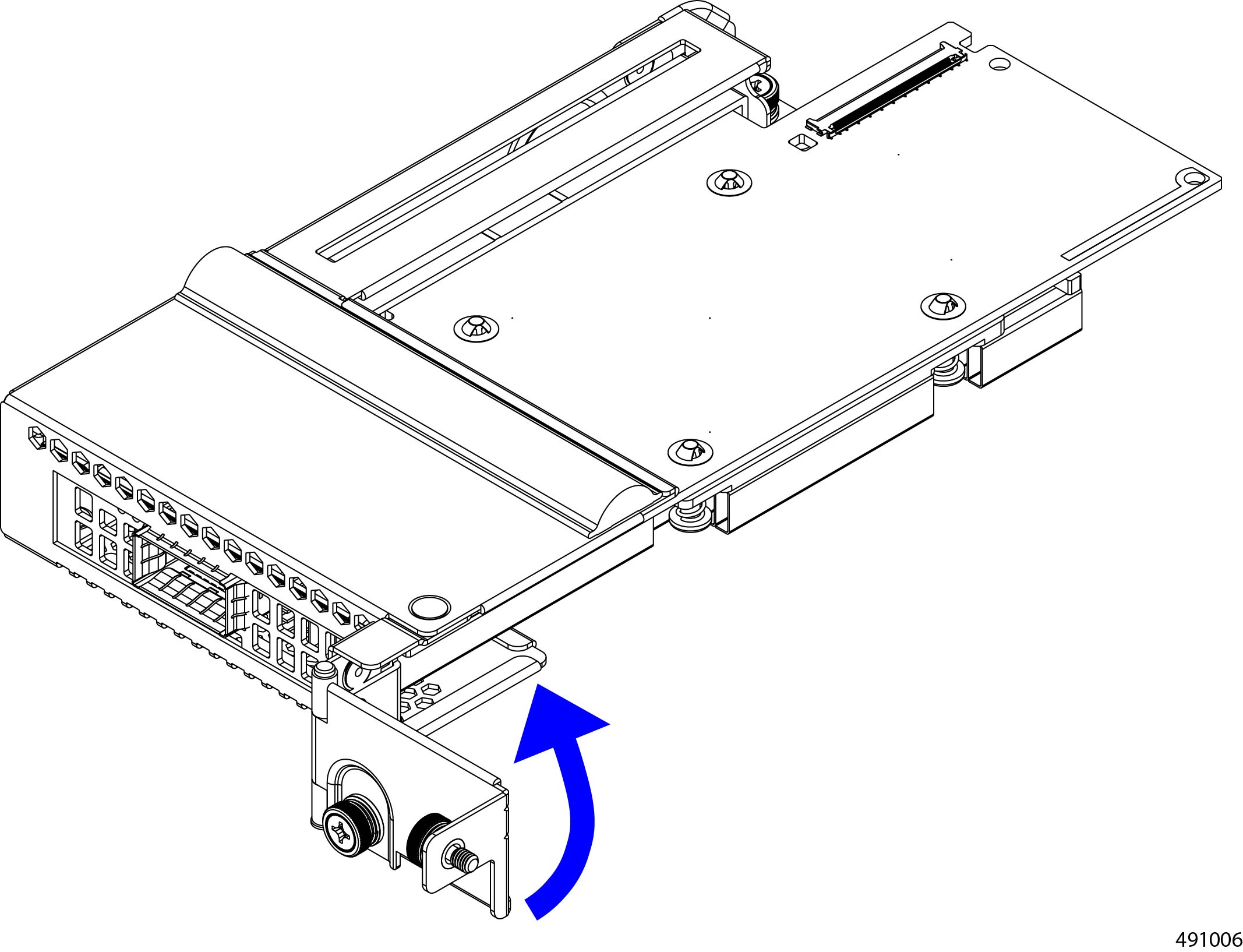
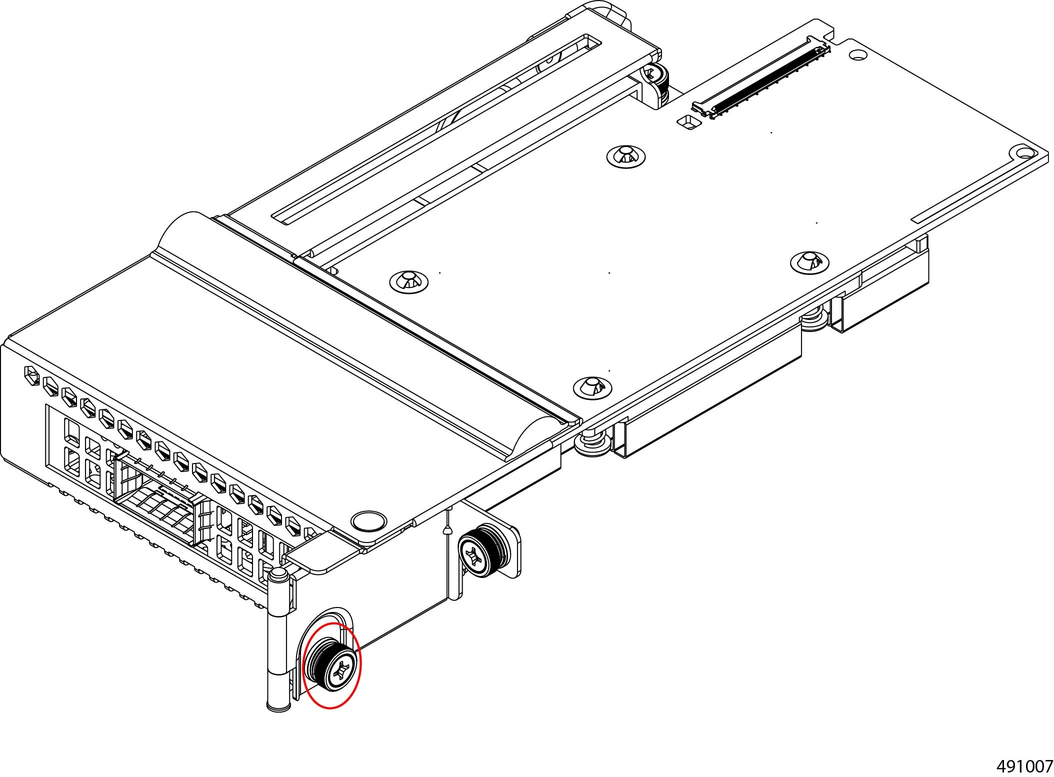
PCIe Cage 2 Supports up to one PCIe Gen5 x16 card, or a filler blank if no card is present. For information about valid PCIe cards, see Cisco UCS X9516 Supported PCIe Cards.
|
4 |
PCIe Cage 1 Supports up to one PCIe Gen5 x16 card, or a filler blank if no card is present. For information about valid PCIe cards, see Cisco UCS X9516 Supported PCIe Cards.
|
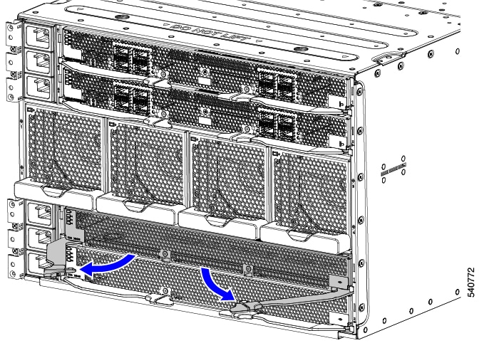
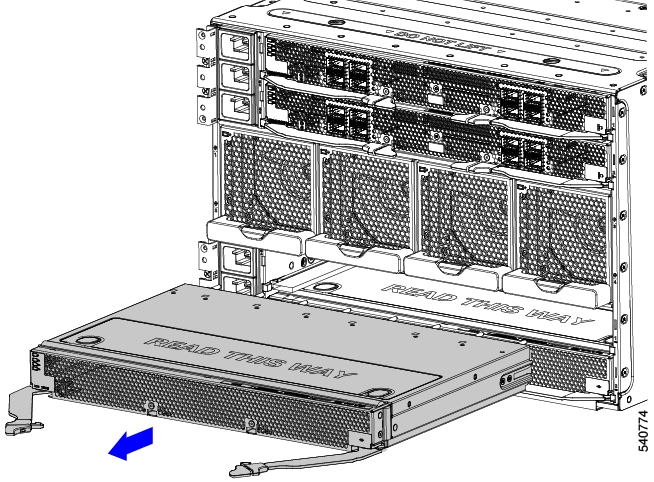
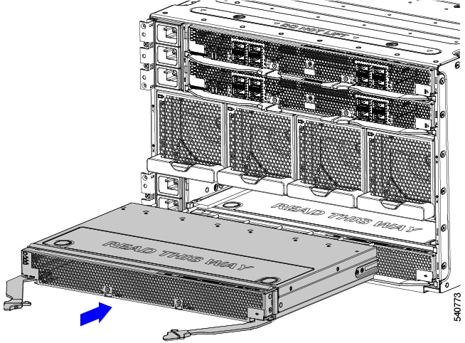
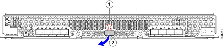
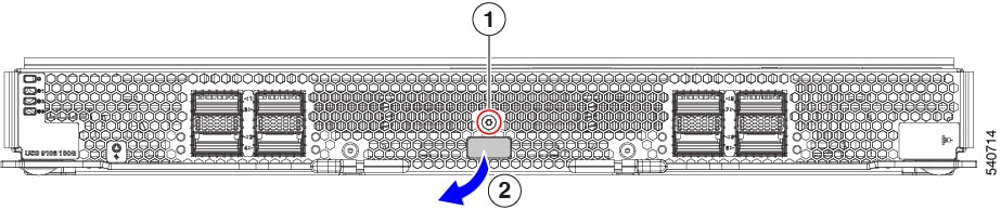
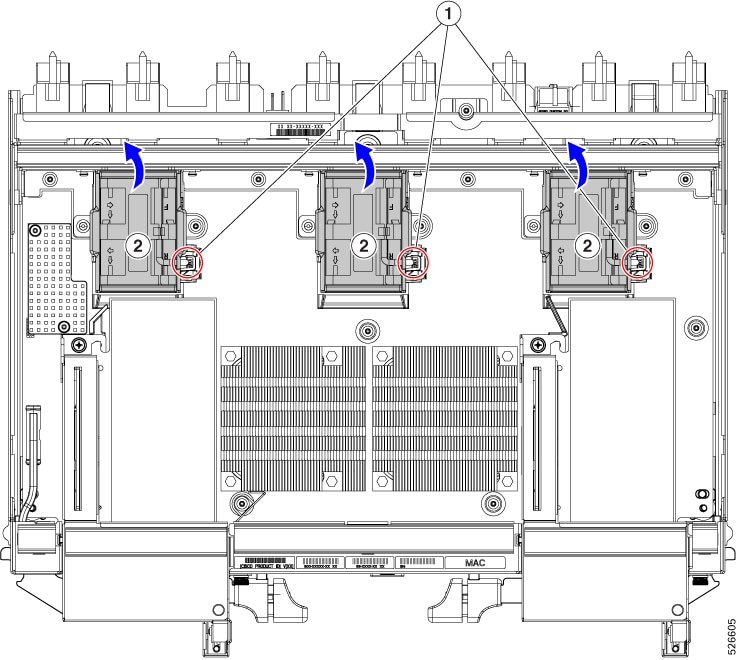
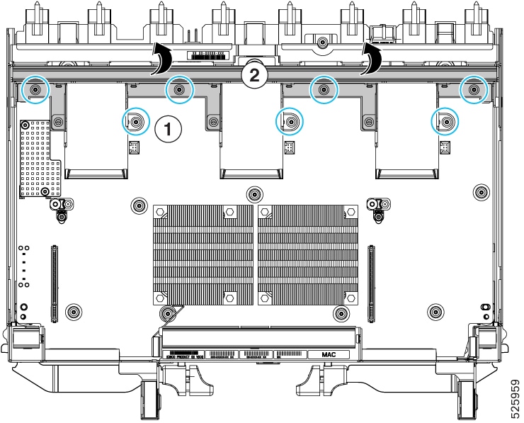
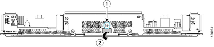
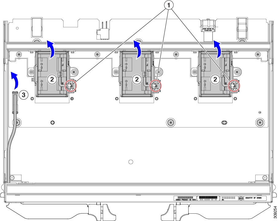
Cisco UCS X-Fabric Module Blank Components
The Cisco X-Fabric Module Blank (UCSX-9508-RBLK) has the following components.
|
1 |
Fans (UCSX-RSFAN=), three, which are numbered 1 through 3 starting with the left fan |
2 |
Module Ejector Handles, Left and Right |


 ).
).
 )
)
 )
)
 Feedback