Preparing for Installation
This section contains the following topics:
Installation Warnings and Guidelines
 Note |
Before you install, operate, or service a server, review the Regulatory Compliance and Safety Information for Cisco UCS C-Series Servers for important safety information. |
 Warning |
IMPORTANT SAFETY INSTRUCTIONS This warning symbol means danger. You are in a situation that could cause bodily injury. Before you work on any equipment, be aware of the hazards involved with electrical circuitry and be familiar with standard practices for preventing accidents. Use the statement number provided at the end of each warning to locate its translation in the translated safety warnings that accompanied this device. Statement 1071 |
Warning |
To prevent the system from overheating, do not operate it in an area that exceeds the maximum recommended ambient temperature of: 35° C (95° F). Statement 1047 |
Warning |
The plug-socket combination must be accessible at all times, because it serves as the main disconnecting device. Statement 1019 |
Warning |
This product relies on the building’s installation for short-circuit (overcurrent) protection. Ensure that the protective device is rated not greater than: 250 V, 15 A. Statement 1005 |
Warning |
Installation of the equipment must comply with local and national electrical codes. Statement 1074 |
Warning |
This unit is intended for installation in restricted access areas. A restricted access area can be accessed only through the use of a special tool, lock, and key, or other means of security. Statement 1017 |
 Caution |
To ensure proper airflow it is necessary to rack the servers using rail kits. Physically placing the units on top of one another or “stacking” without the use of the rail kits blocks the air vents on top of the servers, which could result in overheating, higher fan speeds, and higher power consumption. We recommend that you mount your servers on rail kits when you are installing them into the rack because these rails provide the minimal spacing required between the servers. No additional spacing between the servers is required when you mount the units using rail kits. |
Caution |
Avoid uninterruptible power supply (UPS) types that use ferroresonant technology. These UPS types can become unstable with systems such as the Cisco UCS, which can have substantial current draw fluctuations from fluctuating data traffic patterns. |
When you are installing a server, use the following guidelines:
-
Plan your site configuration and prepare the site before installing the server. See the Cisco UCS Site Preparation Guide for the recommended site planning tasks.
-
Ensure that there is adequate space around the server to allow for accessing the server and for adequate airflow. The airflow in this server is from front to back.
-
Ensure that the air-conditioning meets the thermal requirements listed in the Environmental Specifications.
-
Ensure that the cabinet or rack meets the requirements listed in the Rack Requirements.
-
Ensure that the site power meets the power requirements listed in the Power Specifications. If available, you can use an uninterruptible power supply (UPS) to protect against power failures.
Network Equipment-Building System (NEBS) Statements
NEBS describes the environment of a typical United States Regional Bell Operating Company (RBOC) central office. NEBS is the most common set of safety, spatial, and environmental design standards applied to telecommunications equipment in the United States. It is not a legal or regulatory requirement, but rather an industry requirement.
The following NEBS statements apply to the different models of Cisco UCS C220 M6 server:
Note |
Statement 7001—ESD Mitigation This equipment may be ESD sensitive. Always use an ESD ankle or wrist strap before handling equipment. Connect the equipment end of the ESD strap to an unfinished surface of the equipment chassis or to the ESD jack on the equipment if provided. |
Warning |
Statement 7003—Shielded Cable Shielded Cable Requirements for Intrabuilding Lightning Surge The intrabuilding port(s) of the equipment or subassembly must use shielded intrabuilding cabling/wiring that is grounded at both ends. The following port(s) are considered intrabuilding ports on this equipment: RJ-45 Copper Ethernet Ports |
Note |
Statement 7004—Special Accessories Required to Comply with GR-1089 Emission and Immunity Requirements To comply with the emission and immunity requirements of GR-1089, shielded cables are required for the following ports: RJ-45 Copper Ethernet Ports |
Warning |
Statement 7005—Intrabuilding Lightning Surge and AC Power Fault The intrabuilding port(s) of the equipment or subassembly must not be metallically connected to interfaces that connect to the outside plant (OSP) or its wiring. These interfaces are designed for use as intrabuilding interfaces only (Type 2 or Type 4 ports as described in GR-1089-CORE) and require isolation from the exposed OSP cabling. The addition of primary protectors is not sufficient protection to connect these interfaces metallically to OSP wiring. This statement applies to the intrabuilding ports listed below: RJ-45 Copper Ethernet Ports |
Warning |
Statement 7012—Equipment Interfacing with AC Power Ports Connect this equipment to AC mains that are provided with a surge protective device (SPD) at the service equipment that complies with NFPA 70, the National Electrical Code (NEC). |
Note |
Statement 7013—Equipment Grounding Systems—Common Bonding Network (CBN) This equipment is suitable for installations using the CBN. |
Note |
Statement 7016—Battery Return Conductor Treat the battery return conductor of this equipment as Isolated DC return (DC-I). |
Note |
Statement 7018—System Recover Time The equipment is designed to boot up in less than 30 minutes provided the neighboring devices are fully operational. |
Note |
Statement 8015—Installation Location Network Telecommunications Facilities This equipment is suitable for installation in network telecommunications facilities. |
Note |
Statement 8016—Installation Location Where the National Electric Code (NEC) Applies This equipment is suitable for installation in locations where the NEC applies. |
Note |
These Cisco UCS servers are designed to boot up within 30 minutes provided the neighboring devices are fully operational. |
Rack Requirements
The rack must be of the following type:
-
A standard 19-in. (48.3-cm) wide, four-post EIA rack, with mounting posts that conform to English universal hole spacing, per section 1 of ANSI/EIA-310-D-1992.
-
The rack-post holes can be square 0.38-inch (9.6 mm), round 0.28-inch (7.1 mm), #12-24 UNC, or #10-32 UNC when you use the Cisco-supplied slide rails.
-
The minimum vertical rack space per server must be one rack unit (RU), equal to 1.75 in. (44.45 mm).
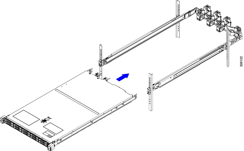
Supported Cisco Slide Rail Kits
The server supports the following rail kit options:
-
Cisco part UCSC-RAIL-M6= (ball-bearing slide rail kit for UCS C220 and C240 M6 rack servers)
-
Cisco part UCSC-CMA-C220M6= (reversible cable management arm for UCS C220 M6 ball-bearing slide rail kit)
Rack Installation Tools Required
The slide rails sold by Cisco Systems for this server do not require tools for installation.
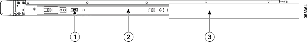
Slide Rail and Cable Management Arm Dimensions
The slide rails for this server have an adjustment range of 24 to 36 inches (610 to 914 mm).
The optional cable management arm (CMA) adds additional length requirements:
-
The additional distance from the rear of the server to the rear of the CMA is 5.4 inches (137.4 mm).
-
The total length of the server including the CMA is 35.2 inches (894 mm).
Front Bezel
An optional locking front bezel (UCSC-BZL-C220M5) is available to provide additional security by preventing unauthorized access to the front-loading SFF drives. The same bezel is used for both M5 and M6 versions of the UCS C220 server.
 Feedback