Supported Storage Controllers and Cables
This server supports a single, PCIe-style, SAS RAID or HBA controller that plugs into a dedicated internal socket.
 Note |
NVMe PCIe SSDs cannot be controlled by a SAS/SATA RAID controller. |
This server supports the RAID and HBA controller options and cable requirements shown in the following table.
|
Storage Adapter (PID) |
Product Name |
Supported Server |
Maximum Number of Drives Supported |
Supported RAID Type |
Cache Size (GB) |
|---|---|---|---|---|---|
|
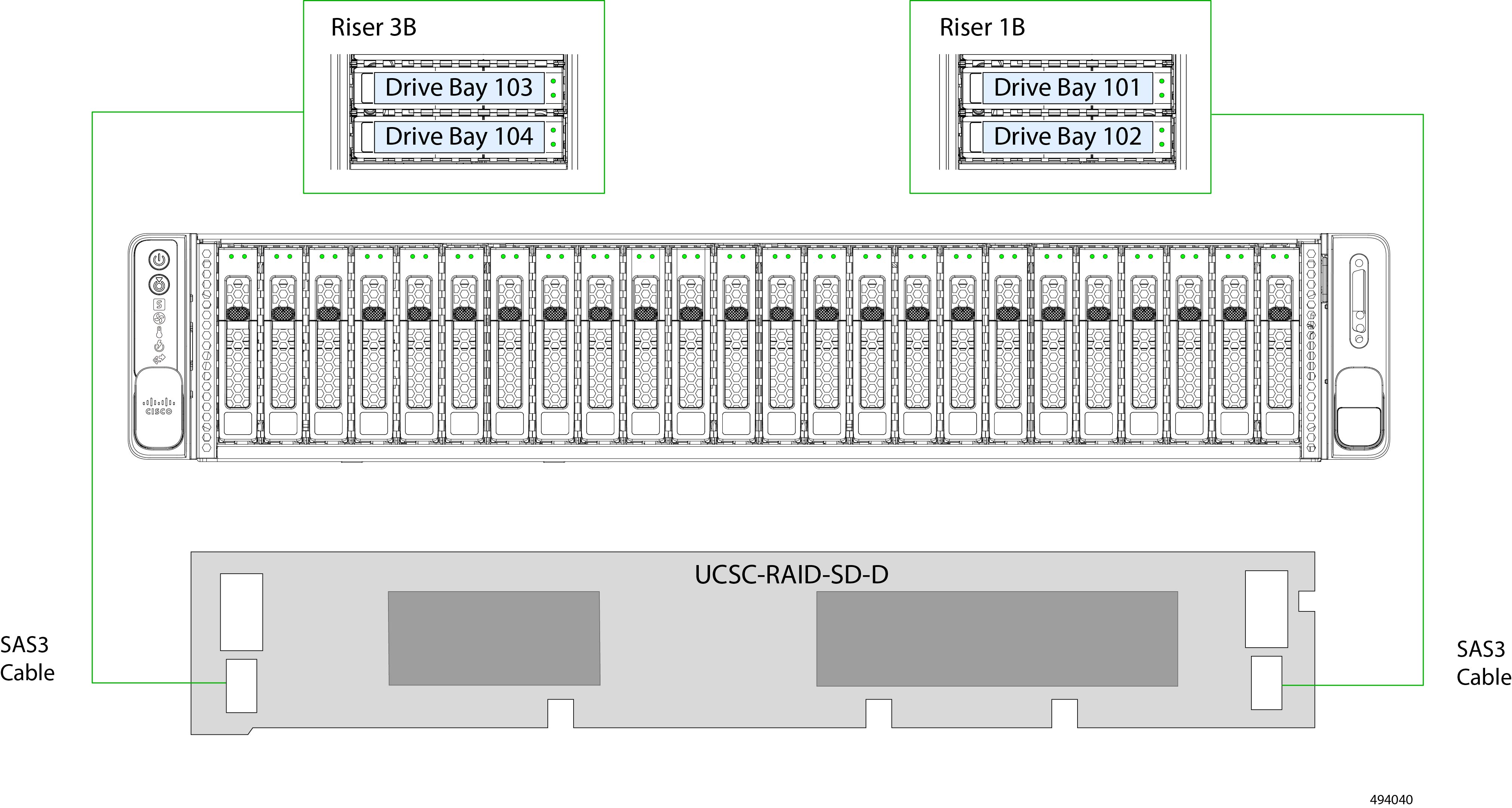
UCSC-RAID-SD-D |
UCSC-C240-M7 SFF servers |
Up to 24 drives total Front-loading HDDs: Up to 24 SAS drives (Gen3) and up to four non-RAID NVMe Gen4 x4 drives in slots 1 through 4) Plus, Rear-loading HDDs: up to 4 SAS HDDs (Gen3) or up to 4 Gen4 x4 NVMe drives (direct-attach). |
RAID No NVMe HW RAID Support |
4 |
|
|
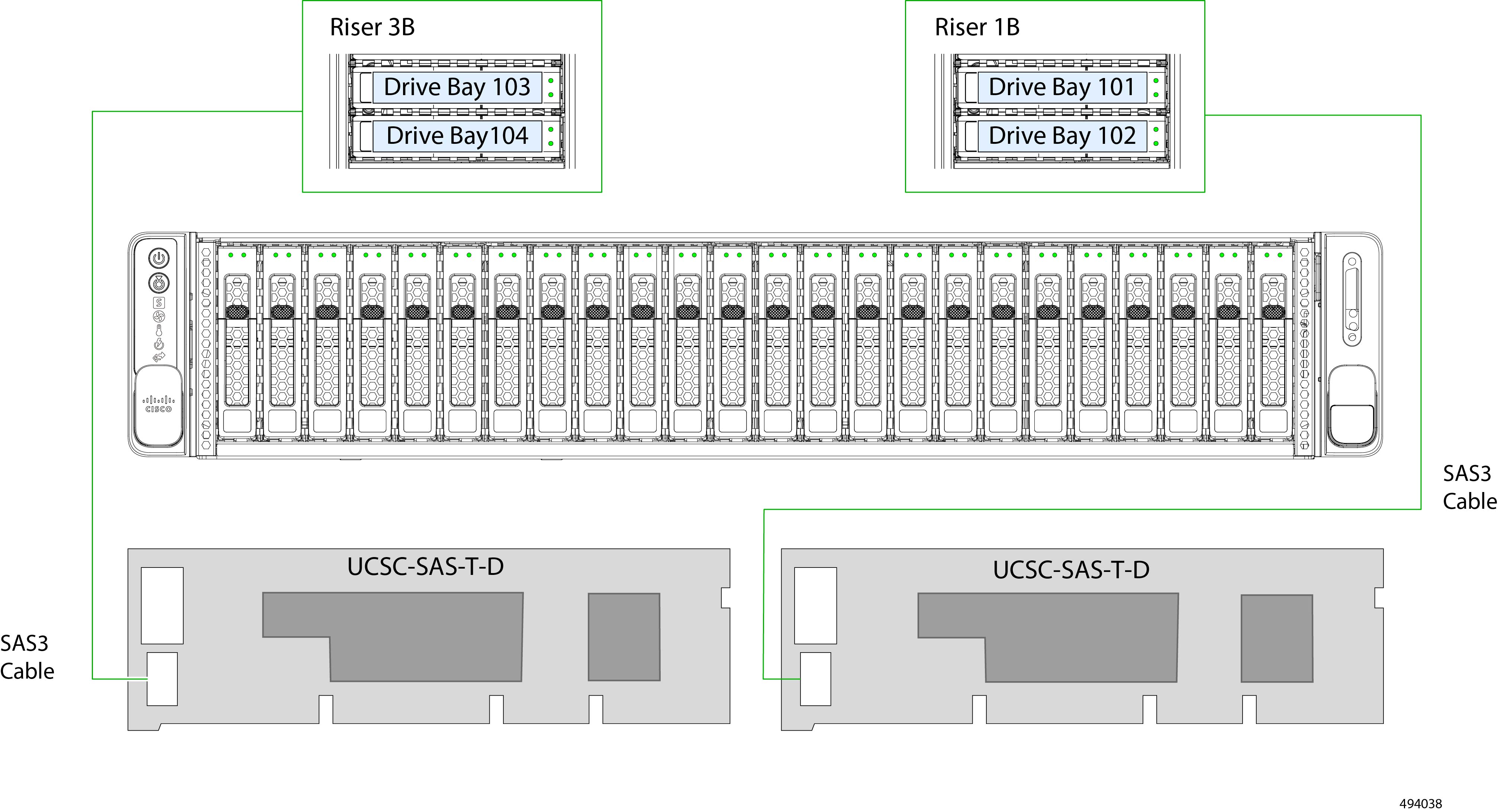
UCSC-SAS-T-D, Two |
UCSC-C240-M7 SFF servers |
20 Front-loading HDDs: Up to 24 SAS drives (Gen3) and up to four non-RAID NVMe Gen4 x4 drives in slots 1 through 4) Plus, Rear-loading HDDs: up to 4 SAS HDDs (Gen3) or up to 4 Gen4 x4 NVMe drives (direct-attach). |
RAID No NVMe HW RAID Support |
NA |
|
|
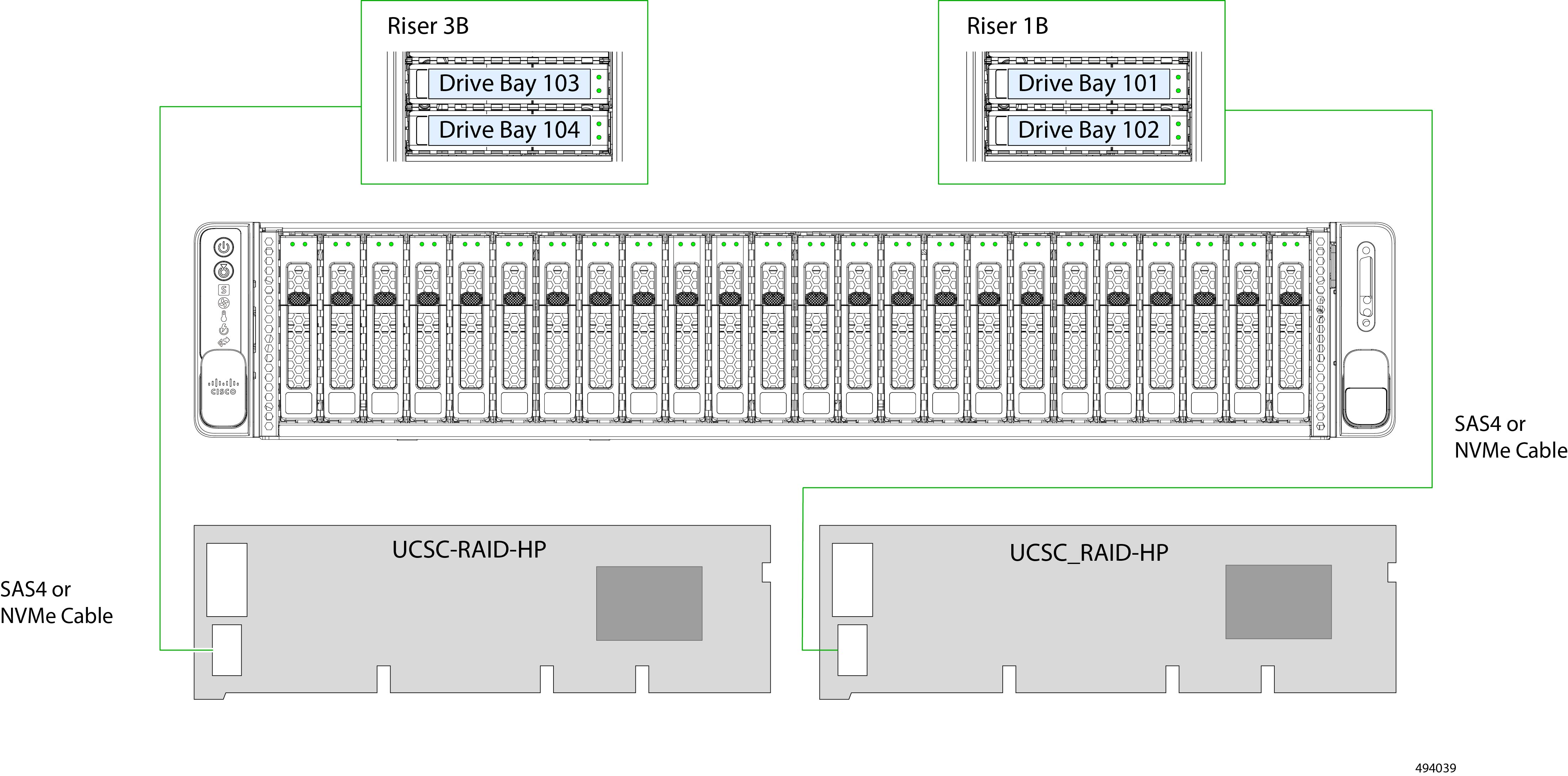
UCSC-RAID-HP, Two |
Cisco UCSC 24G Trim-Mode RAID Controller with 4GB FBWC (16 drives each) |
UCSC-C240-M7 SFF servers |
24 Front-loading HDDs: Up to 24 SAS drives (Gen4, 24 Gbps). No direct-attach NVMe drive support. Plus, Rear-loading HDDs: up to 4 SAS HDDs (Gen4, 24 Gbps) or up to 4 Gen4 x4 NVMe drives. Two controllers, each manages 14 drives Controller 1: Slots 1-12 plus 103 and 104 Controller 2: Slots 13-24 plus 101 and 102 |
RAID NVMe HW RAID support for both front loading and rear-loading |
4 |
|
UCSC-RAID-M1L32 |
UCSC-C240-SFF |
24 Front-loading HDDs: Up to 24 SAS drives (Gen4, 24 Gbps) with up to 4 Gen4 x4 NVMe drives in slots 1 through 4. Plus, Rear-loading HDDs: up to 4 SAS HDDs (Gen424 Gbps) |
RAID |
4 |
|
|
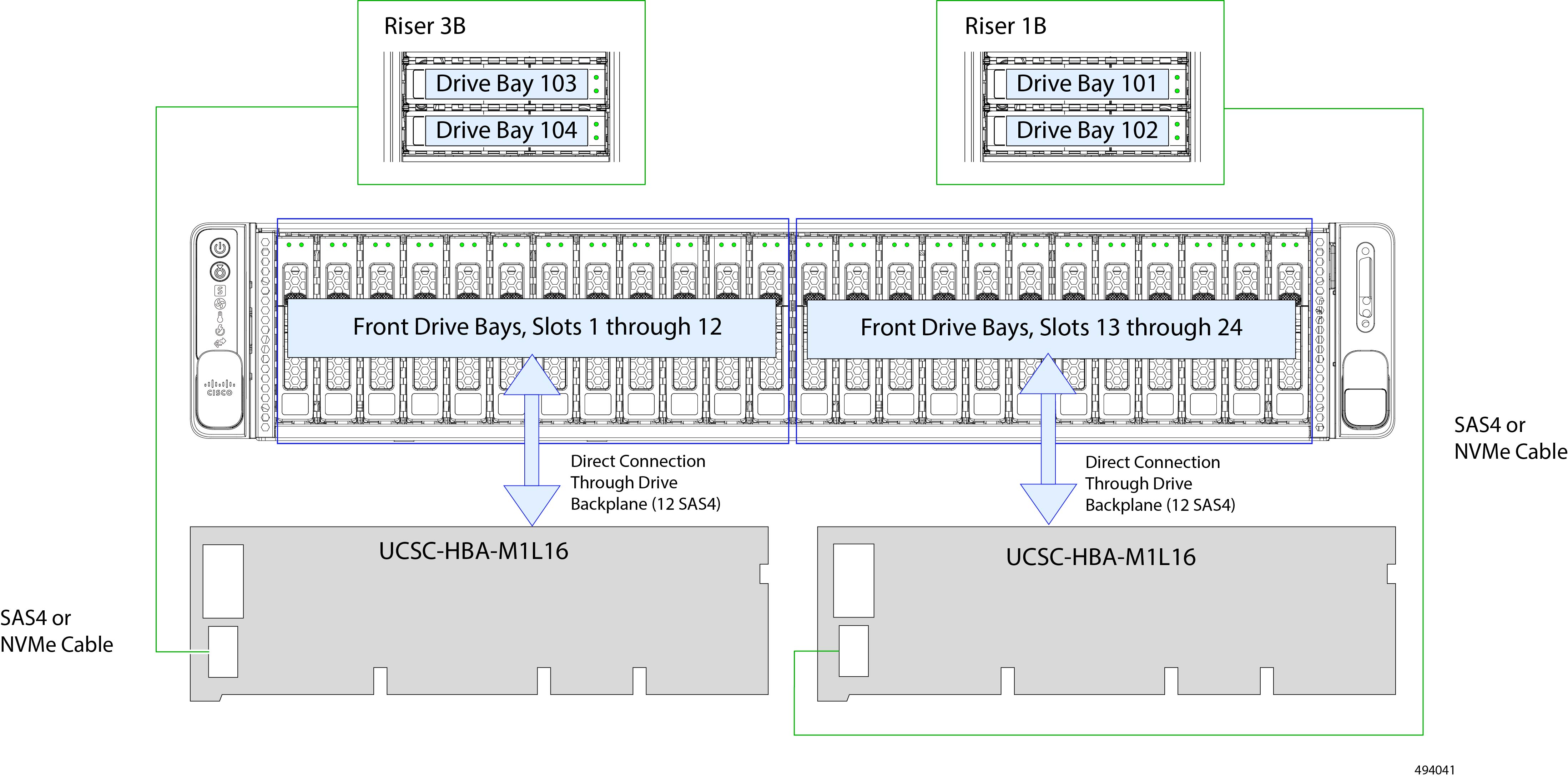
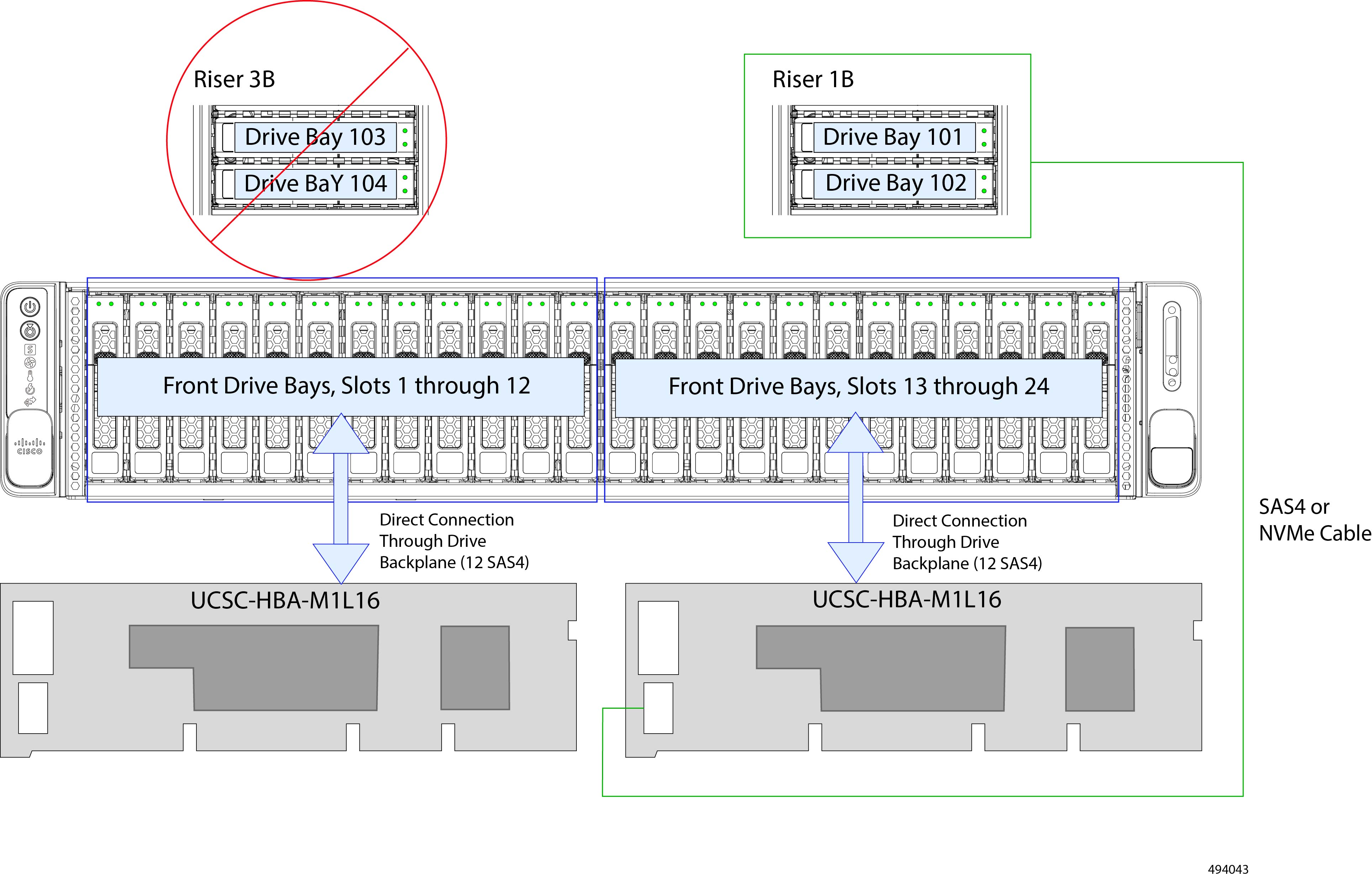
UCSC-HBA-M1L16, Two |
Cisco 12G SAS HBA (16 Drives) |
UCSC-C220-M6S |
24 Front-loading HDDs: Up to 24 SAS drives (Gen4, 24 Gbps), with support for up to four NVMe SSDs (direct attach in slots 1 through 4) Plus, Rear-loading HDDs: up to 4 SAS HDDs (Gen4, 24 Gbps) or up to 4 Gen4 x4 NVMe drives. Two controllers, each manages 16 drives Controller 1: Slots 1-12 plus 103 and 104 Controller 2: Slots 13-24 plus 101 and 102 Plus, Rear-loading HDDs: up to 4 SAS HDDs (Gen4, 24 Gbps) or up to 4 Gen4 x4 NVMe drives. |
SAS HBA |
NA |
|
UCSC-9500-8E-D |
Cisco 9500-8e 12G SAS HBA for external JBOD attach |
All models of UCS C220 M7 and UCS C240 M7 server |
NA |
SAS HBA |
NA |

 Feedback