System Overview

This chapter contains the following topics:

Overview

The Cisco UCS C240 M7 is a stand-alone 2U rack server chassis that can operate in both standalone environments and as part of the Cisco Unified Computing System (Cisco UCS).

Each Cisco UCS C240 M7 has two CPU sockets that can support the following Intel® Xeon® Scalable Processors, in either one or two CPU configurations.

  • Fourth Generation Intel Xeon Scalable Server processors

  • Fifth Generation Intel Xeon Scalable Server processors

Additionally, the server supports the following features with one CPU or two identical CPUs:

  • 32 DDR5 DIMMs (RDIMM), up to 5600 MHz (1DPC) and 4400 MHz (2 DPC) support for RDIMMs.

    16 DIMMs are supported per CPU for a total system memory of 8 TB (up to 256 GB DDR5 DIMMs) on servers with both Intel Fourth and Fifth Generation CPUs.

  • DDR5 DIMM capacities vary based on the CPU type for the compute node. For more information, see DIMM Population Rules and Memory Performance Guidelines.

    • Intel Fourth Generation Xeon Scalable Server Processors support 16, 32, 64, 128, and 256 GB DDR5 DIMMs

    • Intel Fifth Generation Xeon Scalable Server Processors support 16, 32, 64, 96, and 128 GB DDR5 DIMMs.

  • The server's DIMM configuration differs depending on which generation of CPU is populated on the server:

    • With Fourth Generation Intel Xeon Scalable Server processors, the compute node supports DDR5 DIMMs up to 4800 MT/s with 1DPC, and up to 4400 MT/s with 2DPC

    • With Fifth Generation Intel Xeon Scalable Server processors, the compute node supports DDR5 DIMMs up to 5600 MT/s with 1 DPC, and up to 4400 MT/s with 2DPC

  • The servers have different supported configurations of small form factor (SFF) front-loading drives.

  • Up to 2 M.2 SATA RAID cards for server boot.

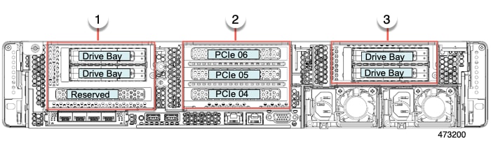
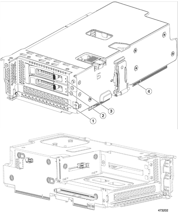
  • Rear Storage risers (2 slots each)
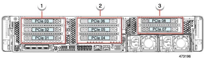
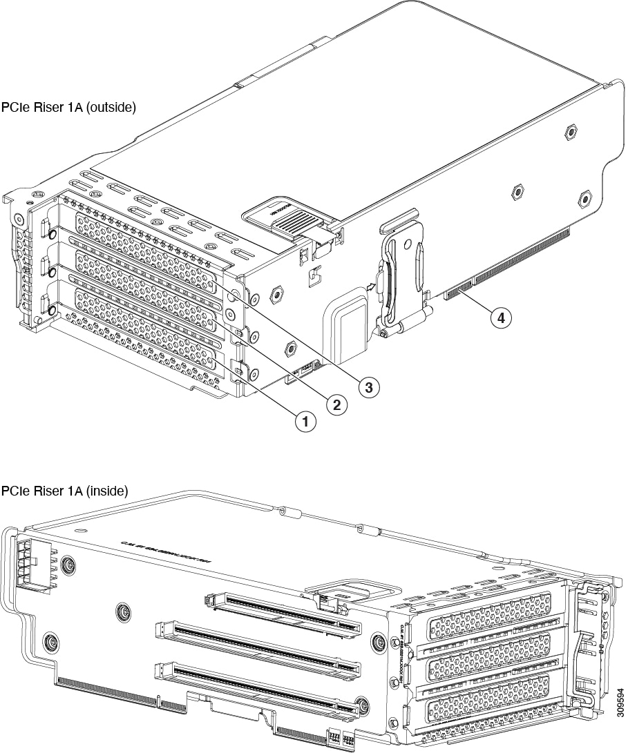
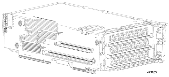
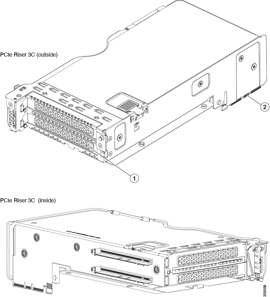
  • Rear PCIe risers

  • Internal slot for a 24 G Tri-Mode RAID controller with SuperCap for write-cache backup, or for a SAS HBA.

  • One mLOM/VIC card provides 10/25/40/50/100/200 Gbps. The following mLOMs are supported:

    • Cisco UCS VIC 15427 Quad Port CNA MLOM (UCSC-M-V5Q50GV2) supports:

      • a x16 PCIe Gen4 Host Interface to the rack server

      • four 10G/25G/50G SFP+/SFP28/SFP56 ports

      • 4GB DDR4 Memory, 3200 MHz

      • Integrated blower for optimal ventilation

      • Secure boot support

    • Cisco UCS VIC 15425 Quad Port 10G/25G/50G SFP56 CNA PCIe (UCSC-P-V5Q50G-D)

      • a x16 PCIe Gen4 Host Interface to the rack server

      • Four 10G/25G/50G QSFP56 ports

      • 4GB DDR4 Memory, 3200MHz

      • Integrated blower for optimal ventilation

    • Cisco UCS VIC 15237 Dual Port 40G/100G/200G QSFP56 mLOM (UCSC-M-V5D200GV2) supports:

      • a x16 PCIe Gen4 Host Interface to the rack server

      • two 40G/100G/200G QSFP/QSFP28/QSFP56 ports

      • 4GB DDR4 Memory, 3200 MHz

      • Integrated blower for optimal ventilation

      • Secure boot support

    • Cisco UCS VIC 15235 Dual Port 40G/100G/200G QSFP56 CNA PCIe (UCSC-P-V5D200G-D)

      • a x16 PCIe Gen4 Host Interface to the rack server

      • two 40G/100G/200G QSFP56 ports

      • 4GB DDR4 Memory, 3200MHz

      • Integrated blower for optimal ventilation

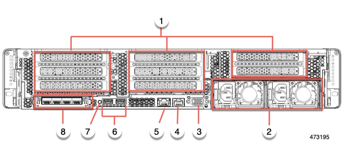
  • Two power AC supplies (PSUs) that support N+1 power configuration and cold redundancy.

  • Six modular, hot swappable fans.

Server Configurations, 24 SFF SAS/SATA

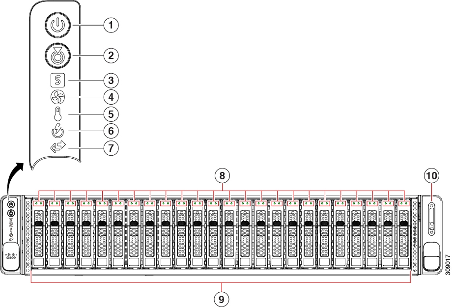
The SFF 24 SAS/SATA/U.3 NVMe configuration (UCSC-C240-M7SX) can be ordered as either an I/O-centric configuration or a storage centric configuration. This server supports the following:

  • A maximum of 24 small form-factor (SFF) drives, with a 24-drive backplane.

    • Front-loading drive bays 1—24 support 2.5-inch SAS/SATA/U.3 drives as SSDs or HDDs.

    • Optionally, drive bays 1—4 can support 2.5-inch NVMe SSDs. In this configuration, any number of NVMe drives can be installed up to the maximum of 4.


      Note


      NVMe drives are supported only on a dual CPU server.


    • Drive bays 5 —24 support SAS/SATA/U.3 SSDs or HDDs only; no U.2 NVMe.

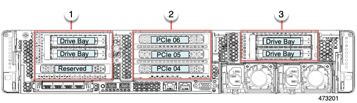
    • Optionally, the rear-loading drive bays support four 4 2.5-inch SAS/SATA or NVMe drives.

Server Configurations, 24 NVMe

The SFF 24 NVMe configuration (UCSC-C240-M7SN) can be ordered as an NVMe-only server. The NVMe-optimized server requires two CPUs. This server supports the following:

  • A maximum of 24 SFF NVMe drives as SSDs with a 24-drive backplane, NVMe-optimized.

    • Front-loading drive bays 1—24 support 2.5-inch NVMe PCIe SSDs only.

    • Optionally, the rear-loading drive bays support four 2.5-inch NVMe SSDs only. These drive bays are in the left and right (Riser 1 and Riser 3) of the rear panel.

External Features

This topic shows the external features of the different configurations of the server.

For definitions of LED states, see Front-Panel LEDs.

Cisco UCS C240 M7 Server 24 SAS/SATA Front Panel Features

The following figure shows the front panel features of Cisco UCS C240 M7SX, which is the small form-factor (SFF), 24 SAS/SATA/U.3 drive version of the server. Front-loading drives can be mix and match in slots 1 through 4 to support up to four SFF NVMe or SFF SAS/SATA drives. UCS C240 M7 servers with any number of NVMe drives must be dual CPU systems.

This configuration can support up to 4 optional universal HDD drives in the rear PCIe slots (riser 1 and Riser 3).

Figure 1. Cisco UCS C240 M7 Server 24 SAS/SATA Front Panel

1

Power Button/Power Status LED

2

Unit Identification Button/Unit Identification LED

3

System Status LEDs

4

Fan Status LED

5

Temperature Status LED

6

Power Supply Status LED

7

Network Link Activity LED

8

Drive Status LEDs

9

NVMe Drive Bays, front loading

Drive bays 1—24 support front-loading SFF SAS/SATA/U.3 NVMe drives.

Drive bays 1 through 4 can support SAS/SATA hard drives and solid-state drives (SSDs) or NVMe PCIe drives. Any number of NVMe drives up to 4 can reside in these slots.

Drive bays 5 - 24 support SAS/SATA/U.3 NVMe drives.

Drive bays are numbered 1 through 24 with bay 1 as the leftmost bay.

10

KVM connector (used with KVM cable that provides one DB-15 VGA, one DB-9 serial, and two USB 2.0 connectors)

Cisco UCS C240 M7 Server 24 NVMe Drives Front Panel Features

The following figure shows the front panel features of Cisco UCS C240 M7SN, which is the small form-factor (SFF) drive, 24 NVMe drive version of the server. Front-loading drives are all NVMe; SAS/SATA drives are not supported. UCS C240 M7 servers with any number of NVMe drives must be dual CPU systems.

This configuration can support up to 4 optional NVMe 2.5-inch drives in the rear PCIe slots (riser 1 and riser 3).

Figure 2. Cisco UCS C240 M7 Server 24 NVMe Front Panel

1

Power Button/Power Status LED

2

Unit Identification LED

3

System Status LEDs

4

Fan Status LED

5

Temperature Status LED

6

Power Supply Status LED

7

Network Link Activity LED

8

Drive Status LEDs

9

Drive bays 1—24 support front-loading SFF NVMe drives.

10

KVM connector (used with KVM cable that provides one DB-15 VGA, one DB-9 serial, and two USB 2.0 connectors)

Common Rear Panel Features

The following illustration shows the rear panel hardware features that are common across all models of the server.

1

Rear hardware configuration options:

  • For I/O-Centric, these are PCIe slots.

  • For Storage-Centric, these are storage drives bays.

This illustration shows the slots unpopulated

2

Power supplies (two, redundant as 1+1)

See Power Specifications for specifications and supported options.

3

VGA video port (DB-15 connector)

4

Serial port (RJ-45 connector)

5

One dedicated 1Gbps management port

6

USB 3.0 ports, 2

7

Rear unit identification button/LED

8

Modular LAN-on-motherboard (mLOM) or OCP card slot (x16).

This slot can contain either a Cisco mLOM or an Intel X710 OCP 3.0 card.

Cisco UCS C240 M7 Server 24 Drive Rear Panel, I/O Centric

The Cisco UCS C240 M7 24 SAS/SATA SFF version has a rear configuration option, for either I/O (I/O Centric) or Storage (Storage Centric) with the I/O Centric version of the server offering PCIe slots and the Storage Centric version of the server offering drive bays.

The following illustration shows the rear panel features for the I/O Centric version of the Cisco UCS C240 M7SX.

  • For features common to all versions of the server, see Common Rear Panel Features.

  • For definitions of LED states, see Rear-Panel LEDs.

1

Riser 1A or 1C

2

Riser 2A or 2C

3

Riser 3A or 3C

-

-

The following table shows the riser options for this version of the server.

Table 1. Cisco UCS C240 M7 24 SFF SAS/SATA/NVMe (UCSC-C240-M7SX)

Riser

Options

Riser 1

This riser is I/O-centric and controlled by CPU 1.

Riser 1A supports three PCIe slots numbered bottom to top:

  • Slot 1 is full-height, ¾ length, x8, NCSI

  • Slot 2 is full-height, full-length, x16, NCSI

  • Slot 3 is full-height, full-length, x8, no NCSI

Riser 1C supports two PCIe slots numbered bottom to top:

  • Slot 1 is full-height, ¾-length, x16 Gen5, NCSI

  • Slot 2 is full-height, full-length, x16 Gen5, no NCSI

Riser 2

This riser is I/O-centric and controlled by CPU 2.

Riser 2A supports three PCIe slots:

  • Slot 4 is full-height, ¾ length, x8, NCSI

  • Slot 5 is full-height, full-length, x16, NCSI

  • Slot 6 is full-height, full-length, x8, no NCSI

Riser 2C supports two PCIe slots, numbered bottom to top:

  • Slot 4 is full-height, ¾-length, x16 Gen5, NCSI

  • Slot 5 is full-height, full-length, x16 Gen5, no NCSI

Riser 3

This riser is I/O-centric and controlled by CPU 2.

Riser 3A supports two PCIe slots:

  • Slot 7 is full-height, full-length, x8

  • Slot 8 is full-height, full-length, x8

Riser 3C supports a GPU only.

  • Supports one full-height, full-length, double-wide GPU (PCIe slot 7 only), x16

  • Slot 8 is blocked by double-wide GPU

Cisco UCS C240 M7 Server 24 NVMe Drive Rear Panel, I/O Centric

The Cisco UCS C240 M7 24 NVMe version has a rear configuration option, for either I/O (I/O Centric) or Storage (Storage Centric) with the I/O Centric version of the server offering PCIe slots and the Storage Centric version of the server offering drive bays.

The following illustration shows the rear panel features for the I/O Centric version of the Cisco UCS C240 M7SN.

  • For features common to all versions of the server, see Common Rear Panel Features.

  • For definitions of LED states, see Rear-Panel LEDs.

The following table shows the riser options for this version of the server.

1

Riser 1A or 1C

2

Riser 2A or 2C

3

Riser 3A, or 3C

-

Table 2. Cisco UCS C240 M7 24 SFF NVMe (UCSC-C240M7-SN)

Riser

Options

Riser 1

This riser is I/O-centric and controlled by CPU 1.

Riser 1A supports three PCIe slots:

  • Slot 1 is full-height, ¾ length, x8, NCSI

  • Slot 2 is full-height, full-length, x16, NCSI

  • Slot 3 is full-height, full-length, x8, no NCSI

Riser 1C supports two PCIe slots numbered bottom to top:

  • Slot 1 is full-height,¾-length, x16 Gen5, NCSI

  • Slot 2 is full-height, full-length, x16 Gen5, no NCSI

Riser 2

This riser is I/O-centric and controlled by CPU 2.

Riser 2A supports three PCIe slots:

  • Slot 4 is full-height, ¾ length, x8

  • Slot 5 is full-height, full-length, x16

  • Slot 6 is full-height, full-length, x8

Riser 2C supports two PCIe slots numbered bottom to top:

  • Slot 4 is full-height,¾-length, x16 Gen5, NCSI

  • Slot 5 is full-height, full-length, x16 Gen5, no NCSI

Riser 3

Riser 3A supports two PCIe slots numbered bottom to top:

  • Slot 7 is full-height, full-length, x8

  • Slot 8 is full-height, full-length, x8

Riser 3C supports a GPU only:

  • Supports one full-height, full-length, double-wide GPU (PCIe slot 7 only), x16

  • Slot 8 is blocked by double-wide GPU

Cisco UCS C240 M7 Server 24 Drive Rear Panel, Storage Centric

The Cisco UCS C240 M7 24 SAS/SATA SFF version has a rear configuration option, for either I/O (I/O Centric) or Storage (Storage Centric) with the I/O Centric version of the server offering PCIe slots and the Storage Centric version of the server offering drive bays.

The following illustration shows the rear panel features for the Storage Centric version of the Cisco UCS C240 M7SX.

  • For features common to all versions of the server, see Common Rear Panel Features.

  • For definitions of LED states, see Rear-Panel LEDs.

The following table shows the riser options for this version of the server.

1

Riser 1B

2

Riser 2Aor 2C

3

Riser 3B

-

Table 3. Cisco UCS C240 M7 24 SFF SAS/SATA/NVMe (UCSC-C240-M7SX)

Riser

Options

Riser 1

This riser is Storage-centric and controlled by CPU 1.

Riser 1B supports two SFF SAS/SATA/NVMe drives

  • Slot 1 is reserved

  • Slot 2 (drive bay 102), x4

  • Slot 3 (drive bay 101), x4

When the server uses a hardware RAID controller card, SAS/SATA HDDs or SSDs, or U.3 NVMe PCIe SSDs are supported in the rear bays.

Riser 2

This riser is I/O-centric and controlled by CPU 2.

Riser 2A and 2C are supported for the Storage-centric version of the server.

Riser 2A supports three slots:

  • Slot 4 is full-height, ¾ length, x8, NCSI

  • Slot 5 is full-height, full-length, x16, NCSI

  • Slot 6 is full-height, full-length, x8

Riser 2C supports two slots:

  • Slot 4 is full-height, ¾-length, x16, Gen 5, NCSI

  • Slot 5 is full-height, full-length, x16, Gen 5

NCSI support is limited to one slot at a time.

Riser 3

This riser is controlled by CPU 2.

Riser 3B has two drive slots that can support two universal HDD or NVMe SFF drives.

  • Slot 7 (drive bay 103), x4

  • Slot 8 (drive bay 104), x4

When the server uses a hardware RAID controller card, SAS/SATA HDDs or SSDs, or U.3 NVME PCIe SSDs, are supported in the rear bays.

Cisco UCS C240 M7 Server 24 NVMe Drive Rear Panel, Storage Centric

The Cisco UCS C240 M7 24 NVMe SFF version has a rear configuration option, for either I/O (I/O Centric) or Storage (Storage Centric) with the I/O Centric version of the server using PCIe slots and the Storage Centric version of the server offering drive bays.

The following illustration shows the rear panel features for the Storage Centric version of the Cisco UCS C240 M7SN.

  • For features common to all versions of the server, see Common Rear Panel Features.

  • For definitions of LED states, see Rear-Panel LEDs.

The following table shows the riser options for this version of the server.

Table 4. Cisco UCS C240 M7 24 SFF NVMe (UCSC-C240M7-SN)

Riser

Options

Riser 1B

This riser is Storage centric and controlled by CPU 1.

Riser 1B supports two universal HDD/NVMe SFF drive slots:

  • Slot 1 is reserved. and does not support HDD or NVMe drives. This slot does support one M.2 NVMe RAID card.

  • Slot 2 (drive bay 102), x4

  • Slot 3 (drive bay 101), x4

When the server uses a hardware RAID controller card, NVMe PCIe SSDs are supported in the rear bays.

Riser 2

Riser 2A and 2C are supported for the Storage-centric version of the server.

Riser 2A supports three slots:

  • Slot 4 is full-height, ¾ length, x8, NCSI

  • Slot 5 is full-height, full-length, x16, NCSI

  • Slot 6 is full-height, full-length, x8

Riser 2C supports two slots:

  • Slot 4 is full-height, ¾-length, x16, Gen 5, NCSI

  • Slot 5 is full-height, full-length, x16, Gen 5

NCSI support is limited to one slot at a time.

Riser 3

In the Storage-Centric configuration, Riser 3B has two slots that can support two universal HDD/NVMe SFF drives.

  • Slot 7 (drive bay 107), x4

  • Slot 8 (drive bay 106), x4

PCIe Risers

The following different PCIe riser options are available.

Riser 1 Options

This riser supports the following options, Riser 1A, 1B (two HDDs only), and 1C.

1

PCIe slot 1, supports full-height, ¾ length, x8, Gen 4, NCSI support for one slot at a time

2

PCIe slot 2, full height, full length, x16, Gen 4, GPU capable, NCSI support for one slot at a time

3

PCIe slot 3, full height, full length, x8, Gen 4, no NCSI

4

Edge Connectors

1

PCIe slot 1, Reserved for drive controller (NVMe M.2 RAID controller)

2

Drive Bay 102, x4, Gen 4, 2.5-inch Universal HDD, SSD, or NVMe

3

Drive 101, x4, Gen 4, 2.5-inch Universal HDD, SSD, or NVMe

4

Edge Connectors

Riser 1C supports two PCIE Gen5 x16 Slots.

The following illustration shows Riser 1C (inside)

The following illustration shows Riser 1C (outside).

1

PCIe slot 1, supports full-height, ¾ length, x16, Gen 5, NCSI support on one slot at a time

2

PCIe slot 2, supports full-height, full length, x16, Gen 5, no NCSI

Riser 2

This riser supports options Riser 2A and 2C, which have the same electrical and mechanical properties as Riser 1A and Riser 1C, but Riser 2 has a different mechanical holder.

1

PCIe slot 4, supports full-height, ¾ length, x8, Gen 4, NCSI support on one slot at a time

2

PCIe slot 5, full height, full length, x16, Gen 4, GPU capable, NCSI support on one slot at a time

3

PCIe slot 6, full height, full length, x8, Gen 4, no NCSI

4

Edge Connectors

Riser 2C supports two PCIE Gen5 x16 Slots.

1

PCIe slot 4, supports full-height, ¾ length, x16, Gen 5, NCSI support on one slot at a time

2

PCIe slot 5, supports full-height, full length, x16, Gen 5, no NCSI

Riser 3

This riser supports three options, 3A, 3B (supports HDD, SSD, and NVMe), and 3C.

1

PCIe slot 7, full height, full length x8, Gen 4, no NCSI

2

PCIe slot 8, full height, full length, x8, Gen 4, no NCSI

3

Edge Connectors

1

PCIe Slot 7, Drive Bay 104, x4, Gen 4, no NCSI

2

PCIe Slot 8, Drive Bay 103, x4, Gen 4, no NCSI

3

Edge Connectors

1

PCIe Slot 7, supports one full height, full length, double-wide GPU (slot 7 only), x16, Gen 4, no NCSI

Note


The other slot is non configurable with hardware.

2

Edge Connectors

Summary of Server Features

The following tables list a summary of the server features.

Table 5. Server Features, SFF

Feature

Description

Chassis

Two rack-unit (2RU) chassis

Central Processor

One or two 4th Generation Intel Xeon processors.

Chipset

Intel® C741 chipset

Memory

32 slots for registered DIMMs (RDIMMs)

Multi-bit error protection

Multi-bit error protection is supported

Video

The Cisco Integrated Management Controller (CIMC) provides video using the Aspeed AST2600 video/graphics controller.

Network and management I/O

Rear panel:

  • One 10-Gb/100-G/1000-Gb Ethernet dedicated management port (RJ-45 connector)

  • One RS-232 serial port (RJ-45 connector)

  • One VGA video connector port (DB-15 connector)

  • Two USB 3.0 ports

  • Identification Button/Identification LED

  • (Optional) Four mLOM ports, 1-Gb/10-GB Ethernet

Front panel:

  • One front-panel keyboard/video/mouse (KVM) connector that is used with the KVM breakout cable. The breakout cable provides two type A USB 2.0 connectors, one VGA (DB-15) connector, and one DB-9 serial connector.

Power

Two of the following Platinum-efficiency hot-swappable power supplies:

  • 1050 W (DC)

  • 1200 W (AC)

  • 1600 W (AC)

  • 2300 W (AC)

Two power supplies are mandatory, and power supplies must be the same. Cold redundancy and 1 + 1 redundancy are supported as long power supplies are the same.

For additional information, see Supported Power Supplies

ACPI

The advanced configuration and power interface (ACPI) 4.0 standard is supported.

Front Panel

The front panel controller provides status indications and control buttons KVM connector.

Cooling

Six hot-swappable fan modules for front-to-rear cooling.

InfiniBand

The PCIe bus slots in this server support the InfiniBand architecture.

Expansion Slots

For the SFF versions of the server, the following expansion slots are supported:

  • Riser 1A (Three PCIe slots)

  • Riser 1B (Two drive bays)

  • Riser 1C (Two PCIe Gen5 slots)

  • Riser 2A (Three PCIe slots)

  • Riser 2C (Two PCIe Gen5 slots)

  • Riser 3A (Two PCIe slots)

  • Riser 3B (Two drive bays)

  • Riser 3C (One PCIe slot)

Note


Not all risers are available in every server configuration option.

Interfaces

Rear panel:

  • One 10/100/1000 Base-T RJ-45 management port

  • One RS-232 serial COM port (RJ45 connector)

  • One DB15 VGA connector

  • Two Type A USB 3.0 port connectors

  • One flexible modular LAN on motherboard (mLOM) slot that can accommodate various interface cards

  • Identification Button/Identification LED

Front panel supports one KVM console connector that supplies:

  • two Type A USB 2.0 connectors

  • one DB-15 VGA video connector

  • one DB-9 serial port connector

Internal Storage Devices

  • UCSC-C240-M7SX:

    • Up to 24 front SFF SAS/SATA hard drives (HDDs) or SAS/SATA/U.3 NVMe SSD solid state drives (SSDs).

    • Two Cisco 24G Tri-mode (16-port) RAID controllers (UCSC-RAID-HP), each supports up to 14 SAS/SATA/U.3 NVMe drives.

    • Two Cisco 24G Tri-mode M1 (16-port) HBA controllers (UCSC-HBA-M1L16), each supports up to 14 SAS/SATA/U.3 NVMe drives.

    • 24G Cisco Tri-Mode MP1 RAID Controller w/4GB FBWC 32Drv w/2U Brkt

    • Optionally, up to four front SFF NVMe PCIe SSDs. These drives must be placed in front drive bays 1, 2, 3, and 4 only. The rest of the bays (5 - 24) can be populated with SAS/SATA/U.3 SSDs or HDDs. Two CPUs are required in a server that has any number of NVMe drives.

    • Optionally, up to four 2.5-inch rear-facing universal drives (SAS/SATA HDDs or SSDs, or NVMe SSDs)

  • UCSC-C240-M7SN:

    • Up to 24 front NVMe drives (only).

    • Optionally, up to 4 rear NVMe drives (only)

    • Two CPUs are required when choosing NVMe SSDs

  • Other Storage:

    • An optional mini-storage module connector on the motherboard supports a boot-optimized RAID controller. The controller can support up two Dual M.2 2280 SATA SSDs which can be used as boot volumes with corresponding interposer/controller cards.

      Mixing different capacity SATA M.2 SSDs is not supported.

Integrated Management Processor

Baseboard Management Controller (BMC) running Cisco Integrated Management Controller (CIMC) firmware.

Depending on your CIMC settings, the CIMC can be accessed through the 1GE dedicated management port, the 1GE/10GE LOM ports or a Cisco virtual interface card (VIC).

CIMC manages certain components within the server, such as the Cisco 12G SAS HBA.

Storage Controllers

  • One Cisco M7 12G SAS RAID controller with 4GB FBWC (for UCSC-240-M7SX server)

    • RAID support (RAID 0, 1, 5, 6, 10, 50, and 60) and SRAID0

    • Supports up to 28 internal drives

  • Two Cisco M7 12G SAS HBA (for UCSC-240-M7SX servers)

    • JBOD/Pass-through Mode support

    • Each HBA supports up to 14 SAS/SATA internal drives

  • Two Cisco 24G Tri-Mode RAID Controller with 4GB cache (UCSC-RAID-HP):

    • Supports up to 24 front-loading SFF SAS/SATA or U.3 NVMe drives plus four rear-loading SFF SAS/SATA or U.3 NVMe drives.

    • Provides RAID 0/1/5/6/10/50/60

    • Supports RAID for U.3 NVMe drives only

    • Drives behind this controller are hot swappable regardless of media type

Modular LAN over Motherboard (mLOM) slot

The dedicated mLOM slot on the motherboard can flexibly accommodate the Cisco Virtual Interface Cards (VICs), Series 15xxx

Server Management

Cisco Intersight provides server management.

CIMC

Cisco Integrated Management Controller (CIMC) 4.3(1) or later is required for the server.

Serviceable Component Locations

This topic shows the locations of the field-replaceable components and service-related items. The view in the following figure shows the server with the top cover removed.

Figure 3. Cisco UCS C240 M7 Server, Serviceable Component Locations

1

Front-loading drive bays.

2

Cooling fan modules (six, hot-swappable)

3

DIMM sockets on motherboard (16 per CPU)

See DIMM Population Rules and Memory Performance Guidelines for DIMM slot numbering.

Note


An air baffle rests on top of the DIMM and CPUs when the server is operating. The air baffle is not displayed in this illustration.

4

CPU socket 2

5

CPU socket 1

6

M.2 RAID Controller

7

PCIe riser 3 (PCIe slots 7 and 8 numbered from bottom to top), with the following options:

  • 3A (Default Option)—Slot 7 (x24 mechanical, x8 electrical, Gen 4)

    Slot 8 (x16 mechanical, x8 electrical, Gen 4)

  • 3B (Storage Option)—Slots 7 and 8, both support x4 electrical, Gen 4.

    Both slots can accept universal SFF HDDs or NVMe SSDs.

  • 3C (GPU Option)—Slot 7 (x24 mechanical, x16 electrical). Slot 7 can support a full height, full length GPU card.

8

PCIe riser 2 (PCIe slots 4, 5, 6 numbered from bottom to top), with the following options:

  • 2A (Default Option)—Slot 4 (x24 mechanical, x8 electrical, Gen 4. NCSI is supported on one slot at a time. Supports a full height, ¾ length card.

    Slot 5 (x24 mechanical, x16 electrical, Gen 4). NCSI is supported on one slot at a time. Supports one full height, full length card.

    Slot 6 (x16 mechanical, x8 electrical, Gen 4). Supports a full height, full length card.

  • 2C— Slots 4 (x24 mechanical, x16 electrical, Gen 5) NCSI supported on one slot at a time. Supports a full-height, full-length card.

    Slot 5 (x24 mechanical, x16 electrical Gen 5) Supports full-height, full-length drive.

9

PCIe riser 1 (PCIe slot 1, 2, 3 numbered bottom to top), with the following options:

  • 1A (Default Option)—Slot 1 (x24 mechanical, x8 electrical, Gen 4) NCSI is supported on one slot at a time. Supports full height, ¾ length card.

    Slot 2 (x24 mechanical, x16 electrical, Gen 4). NCSI is supported on one slot at a time. Supports full height, full length GPU card.

    Slot 3 (x16 mechanical, x8 electrical, Gen 4) Supports full height, full length card.

  • 1B (Storage Option)—Slot 1 supports an M.2 NVMe RAID card

    Slot 2 (x4 electrical), supports universal 2.5-inch HDD NVMe drive

    Slot 3 (x4 electrical), supports universal 2.5-inch HDD NVMe drive

  • 1C — (x24 mechanical, x16 electrical, Gen 5) NCSI supported on one slot at a time. Supports a full-height, ¾-length card.

    Slot 2 (x24 mechanical, x16 electrical, Gen 5) Supports a full-height, full-length card.

-

The Technical Specifications Sheets for all versions of this server, which include supported component part numbers, are at Cisco UCS Servers Technical Specifications Sheets (scroll down to Technical Specifications).