Cisco HyperFlex with CTERA Secure Enterprise File Services using IBM Cloud Object Storage
Available Languages
Bias-Free Language
The documentation set for this product strives to use bias-free language. For the purposes of this documentation set, bias-free is defined as language that does not imply discrimination based on age, disability, gender, racial identity, ethnic identity, sexual orientation, socioeconomic status, and intersectionality. Exceptions may be present in the documentation due to language that is hardcoded in the user interfaces of the product software, language used based on RFP documentation, or language that is used by a referenced third-party product. Learn more about how Cisco is using Inclusive Language.
- US/Canada 800-553-2447
- Worldwide Support Phone Numbers
- All Tools
 Feedback
 Feedback

Cisco HyperFlex with CTERA Secure Enterprise File Services using IBM Cloud Object Storage
Design and Deployment Guide for Cisco HyperFlex and Cisco HyperFlex Edge for Distributed Environments with CTERA Secure Enterprise File Services and IBM Cloud Object Storage as Secondary Storage
Published: August 2020

In partnership with:  and
and ![]()
About the Cisco Validated Design Program
The Cisco Validated Design (CVD) program consists of systems and solutions designed, tested, and documented to facilitate faster, more reliable, and more predictable customer deployments. For more information, go to:
http://www.cisco.com/go/designzone.
ALL DESIGNS, SPECIFICATIONS, STATEMENTS, INFORMATION, AND RECOMMENDATIONS (COLLECTIVELY, "DESIGNS") IN THIS MANUAL ARE PRESENTED "AS IS," WITH ALL FAULTS. CISCO AND ITS SUPPLIERS DISCLAIM ALL WARRANTIES, INCLUDING, WITHOUT LIMITATION, THE WARRANTY OF MERCHANTABILITY, FITNESS FOR A PARTICULAR PURPOSE AND NONINFRINGEMENT OR ARISING FROM A COURSE OF DEALING, USAGE, OR TRADE PRACTICE. IN NO EVENT SHALL CISCO OR ITS SUPPLIERS BE LIABLE FOR ANY INDIRECT, SPECIAL, CONSEQUENTIAL, OR INCIDENTAL DAMAGES, INCLUDING, WITHOUT LIMITATION, LOST PROFITS OR LOSS OR DAMAGE TO DATA ARISING OUT OF THE USE OR INABILITY TO USE THE DESIGNS, EVEN IF CISCO OR ITS SUPPLIERS HAVE BEEN ADVISED OF THE POSSIBILITY OF SUCH DAMAGES.
THE DESIGNS ARE SUBJECT TO CHANGE WITHOUT NOTICE. USERS ARE SOLELY RESPONSIBLE FOR THEIR APPLICATION OF THE DESIGNS. THE DESIGNS DO NOT CONSTITUTE THE TECHNICAL OR OTHER PROFESSIONAL ADVICE OF CISCO, ITS SUPPLIERS OR PARTNERS. USERS SHOULD CONSULT THEIR OWN TECHNICAL ADVISORS BEFORE IMPLEMENTING THE DESIGNS. RESULTS MAY VARY DEPENDING ON FACTORS NOT TESTED BY CISCO.
CCDE, CCENT, Cisco Eos, Cisco Lumin, Cisco Nexus, Cisco StadiumVision, Cisco TelePresence, Cisco WebEx, the Cisco logo, DCE, and Welcome to the Human Network are trademarks; Changing the Way We Work, Live, Play, and Learn and Cisco Store are service marks; and Access Registrar, Aironet, AsyncOS, Bringing the Meeting To You, Catalyst, CCDA, CCDP, CCIE, CCIP, CCNA, CCNP, CCSP, CCVP, Cisco, the Cisco Certified Internetwork Expert logo, Cisco IOS, Cisco Press, Cisco Systems, Cisco Systems Capital, the Cisco Systems logo, Cisco Unified Computing System (Cisco UCS), Cisco UCS B-Series Blade Servers, Cisco UCS C-Series Rack Servers, Cisco UCS S-Series Storage Servers, Cisco UCS Manager, Cisco UCS Management Software, Cisco Unified Fabric, Cisco Application Centric Infrastructure, Cisco Nexus 9000 Series, Cisco Nexus 7000 Series. Cisco Prime Data Center Network Manager, Cisco NX-OS Software, Cisco MDS Series, Cisco Unity, Collaboration Without Limitation, EtherFast, EtherSwitch, Event Center, Fast Step, Follow Me Browsing, FormShare, GigaDrive, HomeLink, Internet Quotient, IOS, iPhone, iQuick Study, LightStream, Linksys, MediaTone, MeetingPlace, MeetingPlace Chime Sound, MGX, Networkers, Networking Academy, Network Registrar, PCNow, PIX, PowerPanels, ProConnect, ScriptShare, SenderBase, SMARTnet, Spectrum Expert, StackWise, The Fastest Way to Increase Your Internet Quotient, TransPath, WebEx, and the WebEx logo are registered trademarks of Cisco Systems, Inc. and/or its affiliates in the United States and certain other countries.
All other trademarks mentioned in this document or website are the property of their respective owners. The use of the word partner does not imply a partnership relationship between Cisco and any other company. (0809R)
© 2020 Cisco Systems, Inc. All rights reserved.
Table of Contents
Cisco Unified Computing System
Cisco UCS S3260 M5 Storage Server
Cisco HyperFlex HX-Series Nodes
Cisco HyperFlex Data Platform Software
Cisco UCS Virtual Interface Card 1455
Cisco UCS 6454 Fabric Interconnect
CTERA Enterprise File Services Platform
Single-site, Multiple-device Failure
Cloud Object Storage Components
Deployment Hardware and Software
Configure Cisco Nexus 93180YC-EX Switch A and B
Initial Setup of Cisco Nexus 93180YC-EX Switch A and B
Enable Features on Cisco Nexus 93180YC-EX Switch A and B
Configure VLANs on Cisco Nexus 93180YC-EX Switch A and B
Configure vPC Domain on Cisco Nexus 93180YC-EX Switch A and B
Configure Network Interfaces for vPC Peer Links on Cisco Nexus 93180YC-EX Switch A and B
Configure Network Interfaces to Cisco UCS FI 6454 on Cisco Nexus 93180YC-EX Switch A and B
Verification Check of Cisco Nexus 93180YC-EX Configuration for Switch A and B
Implement Intelligent Buffer Management for Cisco Nexus 93180YC-EX
Configure Switch Ports for Cisco HX Edge Nodes
Initial Setup of Cisco UCS 6454 Fabric Interconnects
Configure Fabric Interconnect A
Configure Fabric Interconnect B
Enable Fabric Interconnect A Ports for Server
Enable Fabric Interconnect A Ports for Uplinks
Create Port Channel for Fabric Interconnect A/B
Label Each Server for Identification
Configure Cisco UCS Manager for IBM Cloud Object Storage
Create LAN Connectivity Policy
Create Maintenance Policy Setup
Create Power Control Policy Setup
Create vMedia Policy in Cisco UCS Manager
Create Disk Group Policy for Boot Devices
Create Chassis Firmware Package
Create Chassis Maintenance Policy
Create Compute Connection Policy
Create Sas Expander Configuration Policy
Create Chassis Profile Template
Create Chassis Profile from Template
Create Service Profile Template
Create Service Profile Template
Identify Service Profile Template
Create Service Profiles from Template
Installation of Cisco Intersight Virtual Appliance
IP Address and Hostname Requirements
Install Cisco Intersight Virtual Appliance Using VMware vSphere Web Client
Log into Intersight Virtual Appliance
Cisco Intersight Virtual Appliance Settings
Deployment of Cisco HyperFlex Data Platform with Cisco Intersight
Verify Firmware Version for Fabric Interconnect
Configure HyperFlex Fabric Interconnect-Attached Clusters
Create Datastore for CTERA Portal on Cisco HyperFlex
Deployment of Cisco HyperFlex Edge with Cisco Intersight
Change Adapter MLOM Configuration for 25-Gigabit
Verify Firmware Version for HyperFlex Edge Nodes
Configure HyperFlex Edge Cluster
Post-Install Configuration Cisco HyperFlex Edge
Create Datastore for CTERA Edge on Cisco HyperFlex Edge Clusters
CTERA Portal and Edge Installation and Configuration
Import the CTERA Portal OVA File
Prepare for Production Deployment
Log into the CTERA Portal Server
Install the Edge Filer (Gateway) On HyperFlex using vSphere Client
Configure a CTERA Portal as a Precondition to Setting Up the Filer
Validation and Redundancy Testing
Test – HyperFlex Node Failover
Test – HyperFlex Edge Node Failover
Test – Network Uplink Failover HyperFlex Node
Test – Network Uplink Failover HyperFlex Edge Node
Test – HyperFlex Node Drive Failure
Test – HyperFlex Edge Node Drive Failure
Organizations choose the Cisco HyperFlex system to reduce the amount of infrastructure needed to run compute, storage, and network-intensive applications at both the data center and the edge of the network. For many of these enterprises, CTERA’s edge-to-cloud file services platform becomes a natural extension of HyperFlex, seamlessly integrating with the next-generation hyperconverged platform to deliver secure, modern file storage and collaboration. By adding a scalable storage platform like IBM Cloud Object Storage (IBM COS), the whole solution can host data near endless and helps customers reducing costs of primary storage.
Cisco offers a comprehensive infrastructure platform that meets today’s business needs and future innovations. Keeping in mind ease of deployment with different customer use cases, we have validated the following reference architecture for deploying a global network file server (NFS) and small and medium-sized business (SMB) file system solution. Together with the Cisco UCS portfolio of servers, IBM object storage, and CTERA file services, this solution enables enterprises to replace legacy NAS with a cloud-based global file system that delivers infinite storage capacity, fast network performance, multi-site file sharing and collaboration, and significantly reduced costs. The solution comprises CTERA Edge Filers, which serve as a front-end NAS to IBM-powered object storage, providing local SMB/NFS protocols for fast edge performance. CTERA Portal serves as the global file system and data management middleware on which the CTERA solution is delivered.
Introduction
The modernization of corporate file services is a priority for enterprises as they embark on digital transformation initiatives. These file services have comprised a variety of products and use cases, from File Transfer Protocol (FTP) servers or Content Management System (CMS) for collaboration, tape backup for data protection, and, most notably, network attached storage (NAS) and file servers for file storage.
In a globally distributed enterprise, a NAS device traditionally is deployed at each remote office or branch office (ROBO) to address local unstructured data storage needs. These devices must be continuously maintained and regularly upgraded. And to further complicate matters, all the data stored on them needs to be backed up and hauled offsite.
Today’s business requires tools that enable file collaboration, sharing, and access anywhere from desktop to mobile devices.
Scale-up and scale-out versions of NAS devices also have been popular in data center environments for high-volume storage, backup, and archiving of unstructured data. But big NAS appliances are not inexpensive, and the additional costs associated with data replication, data center backup, and bandwidth can rack up quickly.
This reference architecture includes deploying a CTERA Portal virtual machine at the data center with a Cisco HyperFlex platform and CTERA Edge Filers deployed on Cisco HyperFlex Edge at the remote office. CTERA leverages IBM COS with Cisco UCS S3260 server infrastructure for data center storage. It demonstrates management and monitoring of the solution platform through Cisco Intersight to add value in terms of component-level monitoring of the entire solution for fast time-to-value. The Cisco Intersight software is a cloud management platform that provides a holistic approach to managing distributed computing environments from core to edge.
Audience
The intended audience for this document includes, but is not limited to, sales engineers, field consultants, professional services, IT managers, partner engineering, and customers who want to deploy CTERA Portal and Edge Filers on Cisco HyperFlex and Cisco HyperFlex Edge systems with IBM COS on Cisco UCS S3260 M5 Dense Storage Servers.
Purpose of this Document
This document describes how to deploy secure enterprise file services with CTERA on Cisco HyperFlex and Cisco HyperFlex Edge systems with Cisco Intersight, using IBM COS as a Tier 2 storage solution.
It presents a tested and validated solution and provides insight into operational best practices.
What’s New in this Release?
This is the initial version of the solution. The tested IBM COS solution was published in a separate CVD and can be found here: VersaStack for IBM Cloud Object Storage on Cisco UCS S3260.
Solution Summary
In this architecture, the CTERA Edge filers are deployed on Cisco Hyperflex Edge system and CTERA Portal deployed on Cisco HyperFlex system, using Cisco UCS S3260 M5 servers that provide unified storage and serve as the ideal platform for hosting IBM object storage. The solution has six dual-node Cisco UCS S3260 M5 storage servers with IBM Cloud Object Storage software, which serve as capacity tier at the data center but could start with a minimum of three servers. In order to manage IBM and CTERA, we have the management portals hosted on a 4-node Cisco HyperFlex platform. This architecture aligns with the standardization that proposes the HyperFlex standard platform as Hyper Converged Infrastructure (HCI) for the primary data center, and for ROBO (Remote Office Branch Office) proposes Cisco HyperFlex Edge platform with two Cisco HX220c Edge M5 servers to serve as host for CTERA Edge Filer.
IBM COS is configured with the IBM S3 Embedded Accesser nodes, which provides a modern S3 compatible application interface. The CTERA Portal is configured to use the IBM S3 API to access the IBM object storage. The CTERA Portal enables the access to the IBM COS Storage to remote offices via CTERA Edge Filers. Caching feature is enabled as a primary function in CTERA Edge Filers, which continuously sync the entire folder structure of your cloud portal to the Gateway devices and provides accelerated local access to the frequently accessed files.
The configuration uses the following architecture for the deployment:
· 1 x Cisco HyperFlex HX240c M5 4-node cluster
· 2 x Cisco HyperFlex HX220c Edge M5 2-node cluster
· 6 x Cisco UCS S3260 M5 dual-server chassis
· 12 x Cisco UCS S3260 M5 dense storage server
· 2 x Cisco UCS 6454 Fabric Interconnect
· 1 x Cisco UCS Manager
· 1 x Cisco Intersight Virtual Appliance
· 2 x Cisco Nexus 93180YC-EX Switches
Cisco Unified Computing System
Cisco Unified Computing System (Cisco UCS) is a state-of-the-art data center platform that unites computing, network, storage access, and virtualization into a single cohesive system.
The main components of Cisco Unified Computing System are:
· Computing - The system is based on an entirely new class of computing system that incorporates rackmount and blade servers based on Intel Xeon Scalable processors. Cisco UCS servers offer the patented Cisco Extended Memory Technology to support applications with large datasets and allow more virtual machines (VM) per server.
· Network - The system is integrated onto a low-latency, lossless, 10/25/40/100-Gbps unified network fabric. This network foundation consolidates LANs, SANs, and high-performance computing networks which are separate networks today. The unified fabric lowers costs by reducing the number of network adapters, switches, and cables, and by decreasing the power and cooling requirements.
· Virtualization - The system unleashes the full potential of virtualization by enhancing the scalability, performance, and operational control of virtual environments. Cisco security, policy enforcement, and diagnostic features are now extended into virtualized environments to better support changing business and IT requirements.
· Storage access - The system provides consolidated access to both SAN storage and Network Attached Storage (NAS) over the unified fabric. By unifying the storage access, the Cisco Unified Computing System can access storage over Ethernet (NFS or iSCSI), Fibre Channel, and Fibre Channel over Ethernet (FCoE). This provides customers with choice for storage access and investment protection. In addition, the server administrators can pre-assign storage-access policies for system connectivity to storage resources, simplifying storage connectivity, and management for increased productivity.
The Cisco Unified Computing System is designed to deliver:
· A reduced Total Cost of Ownership (TCO) and increased business agility
· Increased IT staff productivity through just-in-time provisioning and mobility support
· A cohesive, integrated system, which unifies the technology in the data center
· Industry standards supported by a partner ecosystem of industry leaders
Cisco UCS S3260 M5 Storage Server
The Cisco UCS S3260 Storage Server is a modular, high-density, high availability, dual-node rack server, well suited for service providers, enterprises, and industry-specific environments. It addresses the need for dense cost-effective storage for the ever-growing data needs. Designed for a new class of cloud-scale applications, it is simple to deploy and excellent for big data applications, software-defined storage environments, and other unstructured data repositories, media streaming, and content distribution.
Extending the capability of the Cisco UCS C3000 portfolio, the Cisco UCS S3260 helps you achieve the highest levels of data availability. With dual-node capability that is based on the Intel Xeon scalable processors, it features up to 840 TB of local storage in a compact 4-rack-unit (4RU) form factor. All hard-disk drives can be asymmetrically split between the dual-nodes and are individually hot-swappable. The drives can be built-in in an enterprise-class Redundant Array of Independent Disks (RAID) redundancy or be in a pass-through mode.
This high-density rack server comfortably fits in a standard 32-inch depth rack, such as the Cisco R42610 Rack.
The Cisco UCS S3260 is deployed as a standalone server in both bare-metal or virtualized environments. Its modular architecture reduces TCO by allowing you to upgrade individual components over time and as use cases evolve, without having to replace the entire system.
The Cisco UCS S3260 uses a modular server architecture that, using Cisco’s blade technology expertise, allows you to upgrade the computing or network nodes in the system without the need to migrate data migration from one system to another. It delivers the following:
· Dual server nodes
· Up to 48 computing cores per server node
· Up to 60 drives mixing a large form factor (LFF) with up to 28 solid-state disk (SSD) drives plus 2 SSD SATA boot drives per server node
· Up to 1.5 TB of memory per server node (3 TB Total) with 128GB DIMMs
· Support for 12-Gbps serial-attached SCSI (SAS) drives
· A system I/O Controller either with HBA Passthrough or RAID controller, with DUAL LSI 3316 Chip
· Cisco VIC 1300 Series Embedded Chip supporting Dual port 40Gbps or Cisco VIC 1400 Series supporting up to 100Gbps
· High reliability, availability, and serviceability (RAS) features with tool-free server nodes, system I/O controller, easy-to-use latching lid, and hot-swappable and hot-pluggable components
· Dual 7mm NVMe – Up to 4 TB per node and 25 TB per chassis
· 1G Host Management Port
Cisco HyperFlex HX-Series Nodes
Cisco HyperFlex systems are built on the Cisco UCS platform which can be deployed quickly and are highly flexible and efficient, reducing risk for the customer. Cisco HyperFlex delivers the simplicity, agility, scalability, and pay-as-you-grow economics of the cloud with the benefits of multisite, distributed computing at global scale.
Cisco HyperFlex Edge is a new version of the Cisco HyperFlex system that is optimized for remote sites, branch offices, and Edge environments. A smaller form factor of the Cisco hyperconverged solution, Cisco HyperFlex Edge offers the full power of a next generation hyperconverged platform without the need to connect to Cisco UCS Fabric Interconnects.
A standard HyperFlex cluster requires a minimum of three HX-Series “converged” nodes (i.e. nodes with shared disk storage). Data is replicated across at least two of these nodes, and a third node is required for continuous operation in the event of a single-node failure. Each node that has disk storage is equipped with at least one high-performance SSD drive for data caching and rapid acknowledgment of write requests. Each node also is equipped with additional disks, up to the platform’s physical limit, for long term storage and capacity.
Cisco HyperFlex HX240c-M5SX Hybrid Node
This capacity optimized Cisco HyperFlex hybrid model contains a minimum of six and up to twenty-three 2.4 TB. 1.8 TB or 1.2 TB SAS small form factor (SFF) hard disk drives (HDD) that contribute to cluster storage, a 240 GB SSD housekeeping drive, a single 1.6 TB SSD caching drive installed in a rear hot swappable slot, and a 240 GB M.2 form factor SSD that acts as the boot drive. Optionally, the Cisco HyperFlex Acceleration Engine card can be added to improve write performance and compression. For configurations requiring self-encrypting drives, the caching SSD is replaced with a 1.6 TB SAS SED SSD, and the capacity disks are replaced with 1.2TB SAS SED HDDs.
Cisco HyperFlex Edge HX-E-220M5SX Hybrid Node
This small footprint Cisco HyperFlex hybrid model contains a minimum of three, and up to eight 2.4 terabyte (TB), 1.8TB or 1.2 TB SAS hard disk drives (HDD) that contribute to cluster storage capacity, a 240 GB SSD housekeeping drive, a 480 GB SATA SSD or 800 GB SAS SSD caching drive, and a 240 GB M.2 form factor SSD that acts as the boot drive.
Cisco HyperFlex Data Platform Software
The Cisco HyperFlex HX Data Platform is a purpose-built, high-performance, distributed file system with a wide array of enterprise-class data management services. The data platform’s innovations redefine distributed storage technology, exceeding the boundaries of first-generation hyperconverged infrastructures. The data platform has all the features expected in an enterprise shared storage system, eliminating the need to configure and maintain complex Fibre Channel storage networks and devices. The platform simplifies operations and helps ensure data availability. Enterprise-class storage features include the following:
· Data protection creates multiple copies of the data across the cluster so that data availability is not affected if single or multiple components fail (depending on the replication factor configured).
· Stretched clusters allow nodes to be evenly split between two physical locations, keeping a duplicate copy of all data in both locations, thereby providing protection in case of an entire site failure.
· Logical availability zones provide multiple logical grouping of nodes and distributes the data across these groups in such a way that no single group has more than one copy of the data. This enables enhanced protection from node failures, allowing for more nodes to fail while the overall cluster remains online.
· Deduplication is always on, helping reduce storage requirements in virtualization clusters in which multiple operating system instances in guest virtual machines result in large amounts of replicated data.
· Compression further reduces storage requirements, reducing costs, and the log-structured file system is designed to store variable-sized blocks, reducing internal fragmentation.
· Replication copies virtual machine level snapshots from one Cisco HyperFlex cluster to another, to facilitate recovery from a cluster or site failure, via a failover to the secondary site of all VMs.
· Encryption stores all data on the caching and capacity disks in an encrypted format, to prevent accidental data loss or data theft. Key management can be done using local Cisco UCS Manager managed keys, or third-party Key Management Systems (KMS) via the Key Management Interoperability Protocol (KMIP).
· Thin provisioning allows large volumes to be created without requiring storage to support them until the need arises, simplifying data volume growth and making storage a “pay as you grow” proposition.
· Fast, space-efficient clones rapidly duplicate virtual storage volumes so that virtual machines can be cloned simply through metadata operations, with actual data copied only for write operations.
· Snapshots help facilitate backup and remote-replication operations, which are needed in enterprises that require always-on data availability.
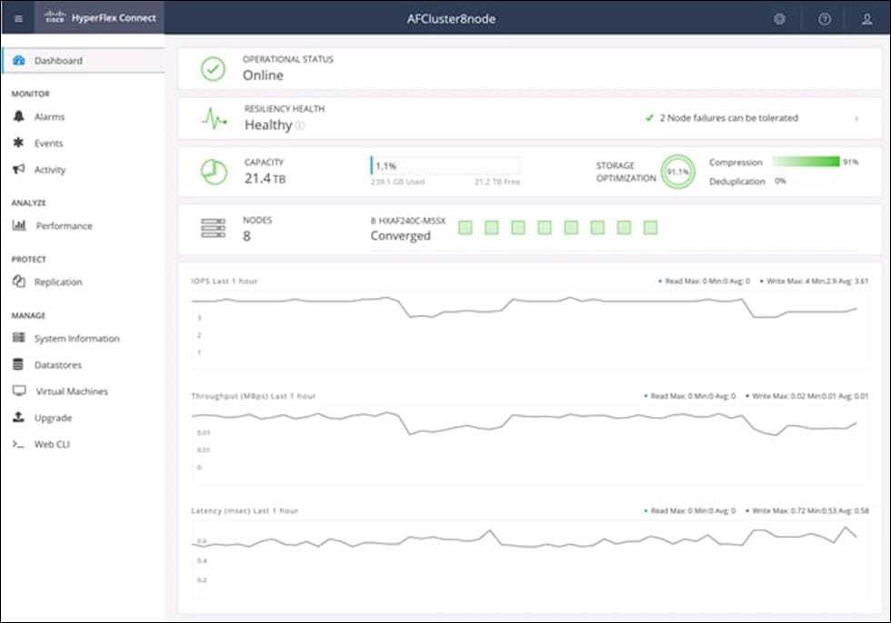
Cisco HyperFlex Connect HTML5 Management Web Page
An HTML 5 based Web UI named HyperFlex Connect is available for use as the primary management tool for Cisco HyperFlex. Through this centralized point of control for the cluster, administrators can create volumes, monitor the data platform health, and manage resource use. Administrators can also use this data to predict when the cluster will need to be scaled. To use the HyperFlex Connect UI, connect using a web browser to the HyperFlex cluster IP address: http://<hx controller cluster ip>.
Cisco Intersight Virtual Appliance Based Management
Cisco Intersight provides comprehensive lifecycle management for the HyperFlex systems, including remote cloud-based installation. Since HXDP version 4.0, support has been extended from 3-node only Edge clusters to include 2, 3 and 4-node Edge clusters to run HyperFlex in different environments. Also, since HXDP version 4.0, the Cisco Intersight Invisible Cloud Witness service is available for supporting 2-node Cisco HyperFlex Edge cluster deployments. The Cisco HX-series rack-mount servers are connected to Cisco Intersight via the network, so that Cisco Intersight can manage and configure the nodes.
Cisco Intersight provides an installation wizard to install, configure, and deploy Cisco HyperFlex Edge clusters. The wizard constructs a pre-configuration definition of the cluster called a HyperFlex Cluster Profile. HyperFlex Cluster Profiles are built on policies in which administrators define sets of rules and operating characteristics, such as the node identity, interfaces, and network connectivity. Every active node in the HyperFlex cluster must be associated with a HyperFlex Cluster Profile. After gathering the node configuration settings to build the HyperFlex Cluster Profile, the installation wizard will validate and deploy the HyperFlex Cluster Profile to your Cisco HX-series nodes, thereby creating a Cisco HyperFlex Edge cluster. You can clone a successfully deployed HyperFlex Cluster Profile, and then use that copy as the basis to create a new cluster.
HyperFlex Policies in Cisco Intersight provide different configurations including Auto Support, security, network configuration and more. A policy that has been configured can be assigned to any number of servers in order to provide a configuration baseline.
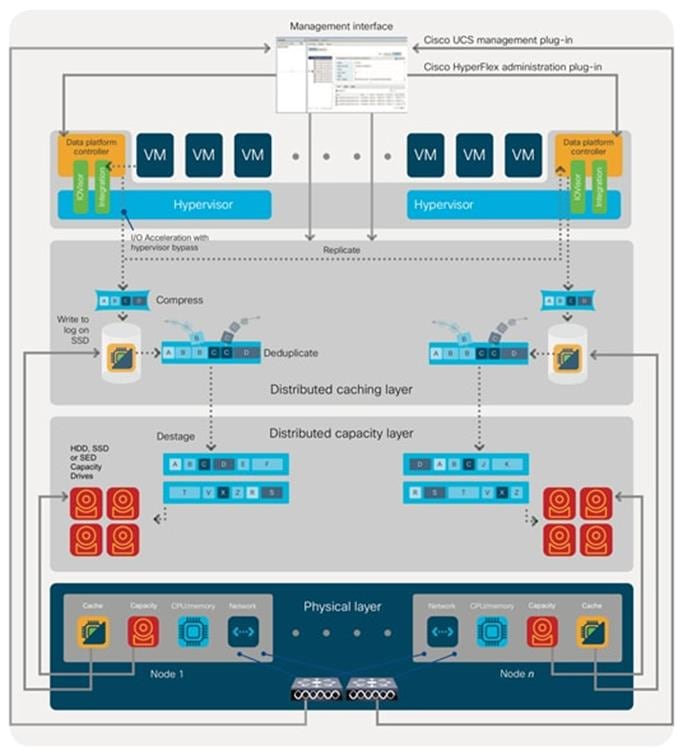
Cisco HyperFlex HX Data Platform Controller
A Cisco HyperFlex HX Data Platform controller resides on each node and implements the distributed file system. The controller runs as software in user space within a virtual machine, and intercepts and handles all I/O from the guest virtual machines. The Storage Controller Virtual Machine (SCVM) uses the VMDirectPath I/O feature to provide direct PCI passthrough control of the physical server’s SAS disk controller, or direct control of the PCI attached NVMe based SSDs. This method gives the controller VM full control of the physical disk resources, utilizing the SSD drives as a read/write caching layer, and the HDDs or SDDs as a capacity layer for distributed storage. The controller integrates the data platform into the VMware vSphere cluster through the use of three preinstalled VMware ESXi vSphere Installation Bundles (VIBs) on each node:
· IO Visor: This VIB provides a network file system (NFS) mount point so that the ESXi hypervisor can access the virtual disks that are attached to individual virtual machines. From the hypervisor’s perspective, it is simply attached to a network file system. The IO Visor intercepts guest VM IO traffic, and intelligently redirects it to the HyperFlex SCVMs.
· VMware API for Array Integration (VAAI): This storage offload API allows vSphere to request advanced file system operations such as snapshots and cloning. The controller implements these operations via manipulation of the filesystem metadata rather than actual data copying, providing rapid response, and thus rapid deployment of new environments.
· stHypervisorSvc: This VIB adds enhancements and features needed for HyperFlex data protection and VM replication.
Data Operations and Distribution
The Cisco HyperFlex HX Data Platform controllers handle all read and write operation requests from the guest VMs to their virtual disks (VMDK) stored in the distributed datastores in the cluster. The data platform distributes the data across multiple nodes of the cluster, and also across multiple capacity disks of each node, according to the replication level policy selected during the cluster setup. This method avoids storage hotspots on specific nodes, and on specific disks of the nodes, and thereby also avoids networking hotspots or congestion from accessing more data on some nodes versus others.
Replication Factor
The policy for the number of duplicate copies of each storage block is chosen during cluster setup and is referred to as the replication factor (RF).
· Replication Factor 3: For every I/O write committed to the storage layer, 2 additional copies of the blocks written will be created and stored in separate locations, for a total of 3 copies of the blocks. Blocks are distributed in such a way as to ensure multiple copies of the blocks are not stored on the same disks, nor on the same nodes of the cluster. This setting can tolerate simultaneous failures of 2 entire nodes in a cluster of 5 nodes or greater, without losing data and resorting to restore from backup or other recovery processes. RF3 is recommended for all production systems.
· Replication Factor 2: For every I/O write committed to the storage layer, 1 additional copy of the blocks written will be created and stored in separate locations, for a total of 2 copies of the blocks. Blocks are distributed in such a way as to ensure multiple copies of the blocks are not stored on the same disks, nor on the same nodes of the cluster. This setting can tolerate a failure of 1 entire node without losing data and resorting to restore from backup or other recovery processes. RF2 is suitable for non-production systems, or environments where the extra data protection is not needed. HyperFlex stretched clusters use the RF2 setting, however there are 2 copies of the data kept in both halves of the cluster, so effectively there are four copies stored.
Data Write and Compression Operations
Internally, the contents of each virtual disk are subdivided and spread across multiple servers by the HXDP software. For each write operation, the data is intercepted by the IO Visor module on the node where the VM is running, a primary node is determined for that particular operation via a hashing algorithm, and then sent to the primary node via the network. The primary node compresses the data in real time, writes the compressed data to the write log on its caching SSD, and replica copies of that compressed data are sent via the network and written to the write log on the caching SSD of the remote nodes in the cluster, according to the replication factor setting. For example, at RF=3 a write operation will be written to write log of the primary node for that virtual disk address, and two additional writes will be committed in parallel on two other nodes. Because the virtual disk contents have been divided and spread out via the hashing algorithm for each unique operation, this method results in all writes being spread across all nodes, avoiding the problems with data locality and “noisy” VMs consuming all the IO capacity of a single node. The write operation will not be acknowledged until all three copies are written to the caching layer SSDs. Written data is also cached in a write log area resident in memory in the controller VM, along with the write log on the caching SSDs. This process speeds up read requests when reads are requested of data that has recently been written.
Data Destaging and Deduplication
The Cisco HyperFlex HX Data Platform constructs multiple write log caching segments on the caching SSDs of each node in the distributed cluster. As write cache segments become full and based on policies accounting for I/O load and access patterns, those write cache segments are locked and new writes roll over to a new write cache segment. The data in the now locked cache segment is destaged to the HDD capacity layer of the nodes for the Hybrid system or to the SSD capacity layer of the nodes for the All-Flash or All-NVMe systems. During the destaging process, data is deduplicated before being written to the capacity storage layer, and the resulting data can now be written to the HDDs or SDDs of the server. On hybrid systems, the now deduplicated and compressed data is also written to the dedicated read cache area of the caching SSD, which speeds up read requests of data that has recently been written. When the data is destaged to the capacity disks, it is written in a single sequential operation, avoiding disk head seek thrashing on the spinning disks and accomplishing the task in the minimal amount of time. Since the data is already deduplicated and compressed before being written, the platform avoids additional I/O overhead often seen on competing systems, which must later do a read/dedupe/compress/write cycle. Deduplication, compression and destaging take place with no delays or I/O penalties to the guest VMs making requests to read or write data, which benefits both the HDD and SDD configurations.
Data Read Operations
For data read operations, data may be read from multiple locations. For data that was very recently written, the data is likely to still exist in the write log of the local platform controller memory, or the write log of the local caching layer disk. If local write logs do not contain the data, the distributed filesystem metadata will be queried to see if the data is cached elsewhere, either in write logs of remote nodes, or in the dedicated read cache area of the local and remote caching SSDs of hybrid nodes. Finally, if the data has not been accessed in a significant amount of time, the filesystem will retrieve the requested data from the distributed capacity layer. As requests for reads are made to the distributed filesystem and the data is retrieved from the capacity layer, the caching SSDs of hybrid nodes populate their dedicated read cache area to speed up subsequent requests for the same data. This multi-tiered distributed system with several layers of caching techniques, ensures that data is served at the highest possible speed, leveraging the caching SSDs of the nodes fully and equally. All-flash and all-NVMe configurations do not employ a dedicated read cache, because such caching does not provide any performance benefit since the persistent data copy already resides on high-performance SSDs.
In summary, the Cisco HyperFlex HX Data Platform implements a distributed, log-structured file system that performs data operations via two configurations:
· In a Hybrid configuration, the data platform provides a caching layer using SSDs to accelerate read requests and write responses, and it implements a storage capacity layer using HDDs.
· In an All-Flash or all-NVMe configuration, the data platform provides a dedicated caching layer using high endurance SSDs to accelerate write responses, and it implements a storage capacity layer also using SSDs. Read requests are fulfilled directly from the capacity SSDs, as a dedicated read cache is not needed to accelerate read operations.
Cisco UCS Virtual Interface Card 1455
The Cisco UCS VIC 1455 is a quad-port Small Form-Factor Pluggable (SFP28) half-height PCIe card designed for the M5 generation of Cisco UCS C-Series Rack Servers. The card supports 10/25-Gbps Ethernet or FCoE. The card can present PCIe standards-compliant interfaces to the host, and these can be dynamically configured as either NICs or HBAs.
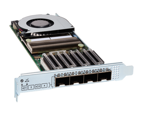
The Cisco UCS VIC 1400 series provides the following features and benefits:
· Stateless and agile platform: The personality of the card is determined dynamically at boot time using the service profile associated with the server. The number, type (NIC or HBA), identity (MAC address and Worldwide Name [WWN]), failover policy, bandwidth, and Quality-of-Service (QoS) policies of the PCIe interfaces are all determined using the service profile. The capability to define, create, and use interfaces on demand provides a stateless and agile server infrastructure.
· Network interface virtualization: Each PCIe interface created on the VIC is associated with an interface on the Cisco UCS fabric interconnect, providing complete network separation for each virtual cable between a PCIe device on the VIC and the interface on the Fabric Interconnect.
Cisco UCS 6454 Fabric Interconnect
The Cisco UCS 6454 Fabric Interconnect is a core part of the Cisco Unified Computing System, providing both network connectivity and management capabilities for the system (Figure 1). The Cisco UCS 6454 offers line-rate, low-latency, lossless 10/25/40/100 Gigabit Ethernet, Fibre Channel over Ethernet (FCoE), and Fibre Channel functions.
The Cisco UCS 6454 provides the management and communication backbone for the Cisco UCS B-Series Blade Servers, Cisco UCS 5108 B-Series Server Chassis, Cisco UCS Managed C-Series Rack Servers, and Cisco UCS S-Series Storage Servers. All servers attached to the Cisco UCS 6454 Fabric Interconnect become part of a single, highly available management domain. In addition, by supporting a unified fabric, the Cisco UCS 6454 provides both the LAN and SAN connectivity for all servers within its domain.
From a networking perspective, the Cisco UCS 6454 uses a cut-through architecture, supporting deterministic, low-latency, line-rate 10/25/40/100 Gigabit Ethernet ports, switching capacity of 3.82 Tbps, and 160 Gbps bandwidth between FI 6454 and IOM 2208 per 5108 blade chassis, independent of packet size and enabled services. The product family supports Cisco® low-latency, lossless 10/25/40/100 Gigabit Ethernet unified network fabric capabilities, which increase the reliability, efficiency, and scalability of Ethernet networks. The Fabric Interconnect supports multiple traffic classes over a lossless Ethernet fabric from the server through the Fabric Interconnect. Significant TCO savings come from an FCoE optimized server design in which Network Interface Cards (NICs), Host Bus Adapters (HBAs), cables, and switches can be consolidated.
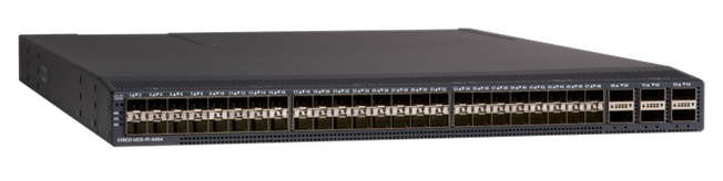
The Cisco UCS 6454 54-Port Fabric Interconnect is a One-Rack-Unit (1RU) 10/25/40/100 Gigabit Ethernet, FCoE and Fibre Channel switch offering up to 3.82 Tbps throughput and up to 54 ports. The switch has 28 10/25-Gbps Ethernet ports, 4 1/10/25-Gbps Ethernet ports, 6 40/100-Gbps Ethernet uplink ports and 16 unified ports that can support 10/25-Gbps Ethernet ports or 8/16/32-Gbps Fibre Channel ports. All Ethernet ports are capable of supporting FCoE.
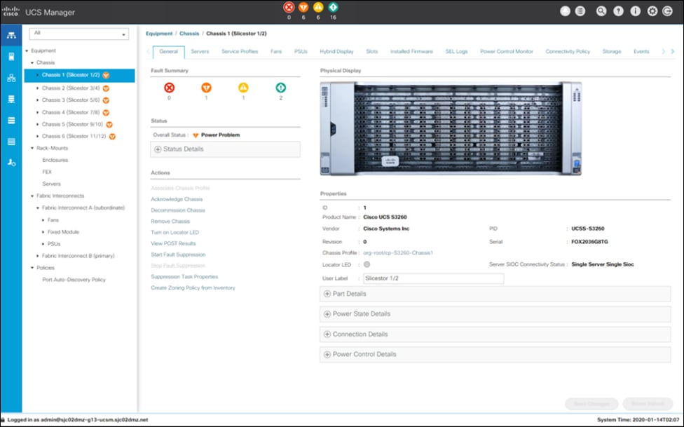
Cisco UCS Manager
Cisco UCS Manager supports the entire Cisco UCS server and Cisco HyperFlex Series hyperconverged infrastructure portfolios. It enables server, fabric, and storage provisioning as well as, device discovery, inventory, configuration, diagnostics, monitoring, fault detection, auditing, and statistics collection. You can extend the benefits of Cisco UCS Manager globally across an enterprise to thousands of servers in multiple domains with Cisco UCS Central Software.
The open platform treats infrastructure as code. It extends the functionality of existing management tools through a broad, mature partner ecosystem. IT organizations can transition to DevOps by evolving existing staff, skills, tools, and processes and making them more efficient, to gain TCO savings.
An open API facilitates integration of Cisco UCS Manager with a wide variety of monitoring, analysis, configuration, deployment, and orchestration tools from other independent software vendors. The API also facilitates customer development through the Cisco UCS PowerTool for PowerShell and a Python SDK.
Key Features:
· Supports Cisco UCS B-Series Blade and C-Series Rack Servers, the Cisco UCS C3260 storage server, Cisco UCS Mini, and the Cisco HyperFlex hyperconverged infrastructure
· Programmatically controls server, network, and storage resources, with a unified, policy-driven management, so they can be efficiently managed at scale through software
· Works with HTML 5, Java, or CLI graphical user interfaces
· Can automatically detect, inventory, manage, and provision system components that are added or changed
· Facilitates integration with third-party systems management tools
· Builds on existing skills and supports collaboration across disciplines through role-based administration
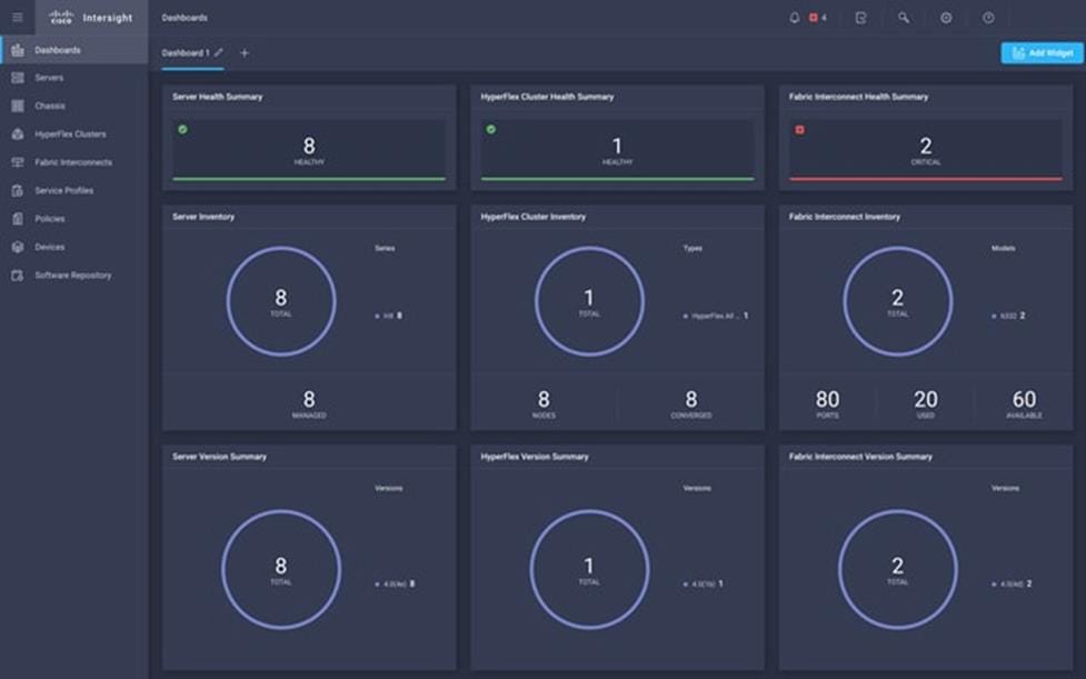
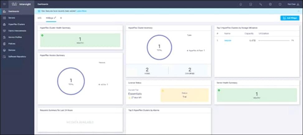
Cisco Intersight
Cisco Intersight (https://intersight.com) is an API driven, cloud-based system management platform. It is designed to help organizations to achieve their IT management and operations with a higher level of automation, simplicity, and operational efficiency. It is a new generation of global management tool for the Cisco Unified Computing System (Cisco UCS) and Cisco HyperFlex systems and provides a holistic and unified approach to managing the customers’ distributed and virtualized environments. Cisco Intersight simplifies the installation, monitoring, troubleshooting, upgrade, and support for your infrastructure with the following benefits:
· Cloud Based Management: The ability to manage Cisco UCS and HyperFlex from the cloud provides the customers the speed, simplicity, and easy scaling in the management of their infrastructure whether in the datacenters or remote and branch office locations.
· Automation: Unified API in Cisco UCS and Cisco HyperFlex systems enables policy driven configuration and management of the infrastructure and it makes Intersight itself and the devices connected to it fully programmable and DevOps friendly.
· Analytics and Telemetry: Intersight monitors the health and relationships of all the physical and virtual infrastructure components. It also collects telemetry and configuration information for developing the intelligence of the platform in the way in accordance with Cisco information security requirements.
· Connected TAC: Solid integration with Cisco TAC enables more efficient and proactive technical support. Intersight provides enhanced operations automation by expediting sending files to speed troubleshooting.
· Recommendation Engine: Driven by analytics and machine learning, Intersight recommendation engine provides actionable intelligence for IT operations management from daily increasing knowledge base and practical insights learned in the entire system.
· Management as A Service: Cisco Intersight provides management as a service and is designed to be infinitely scale and easy to implement. It relieves users of the burden of maintaining systems management software and hardware.
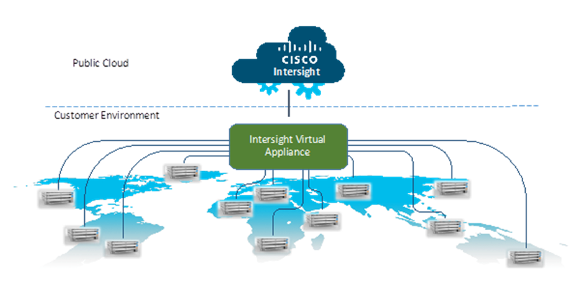
Intersight Virtual Appliance
The Cisco Intersight Virtual Appliance delivers the management features of Intersight for Cisco UCS and HyperFlex into the on-premise environment. It is deployed from a VMware OVA that enables the additional control to specify what data is sent back to Cisco with a single point of egress within the enterprises network. The virtual appliance form factor enables additional data locality, security, or compliance needs that are not completely met by connecting directly to intersight.com in the cloud. However, The Cisco Intersight Virtual Appliance is not intended for an environment with no external connectivity, the Cisco Intersight virtual appliance requires an internet connection back to Cisco and the cloud-based Intersight services for updates and to deliver some of the product features. Communication back to Cisco can be redirected via a proxy server if direct connectivity is not available or allowed by policy. Updates to the virtual appliance are automated and applied during a user specified recurring maintenance window. This connection also facilitates the streamlining of Cisco TAC services for Cisco UCS and HyperFlex systems, with features like automated support log collection.
Cisco Intersight Virtual Appliance OVA can be downloaded from Cisco website and can be deployed as a virtual machine in your existing environment. Cisco Intersight Virtual Appliance uses a subscription-based license delivered via Cisco Smart Licensing. After the installation of the appliance OVA is completed, you must connect the appliance to Cisco Intersight, and register the license as part of the initial setup process.
Cisco Nexus 93180YC-EX
The Cisco Nexus® 9300-EX Series switches belongs to the fixed Cisco Nexus 9000 platform based on Cisco Cloud Scale technology. The platform support cost-effective cloud-scale deployments, an increased number of endpoints, and cloud services. The platform is built on modern system architecture designed to provide high performance and meet the evolving needs of highly scalable data centers and growing enterprises.
Cisco Nexus 9300-EX series switches offer a variety of interface options to transparently migrate existing data centers from 100-Mbps, 1-Gbps, and 10-Gbps speeds to 25-Gbps at the server, and from 10- and 40-Gbps speeds to 50- and 100-Gbps at the aggregation layer. The platforms provide investment protection for customers, delivering large buffers, highly flexible Layer 2 and Layer 3 scalability, and performance to meet the changing needs of virtualized data centers and automated cloud environments.
Cisco provides two modes of operation for Cisco Nexus 9000 Series Switches. Organizations can use Cisco NX-OS Software to deploy the switches in standard Cisco Nexus switch environments (NX-OS mode). Organizations can also deploy the infrastructure that is ready to support the Cisco Application Centric Infrastructure (Cisco ACI™) platform to take full advantage of an automated, policy-based, systems-management approach (ACI mode).
The Cisco Nexus 93180YC-EX Switch is a 1-Rack-Unit (1RU) switch with latency of less than 1 microsecond that supports 3.6 Terabits per second (Tbps) of bandwidth and over 2.6 billion packets per second (bpps). The 48 downlink ports on the 93180YC-EX can be configured to work as 1-, 10-, or 25-Gbps ports, offering deployment flexibility and investment protection. The uplink can support up to six 40- and 100-Gbps ports, or a combination of 1-, 10-, 25-, 40-, 50, and 100-Gbps connectivity, offering flexible migration options. The switch has FC-FEC enabled for 25Gbps and supports up to 3m in DAC connectivity. Please check Cisco Optics Matrix for the most updated support.

CTERA Enterprise File Services Platform
CTERA delivers a next-generation global file system that connects remote sites and users to any cloud infrastructure without compromising security or performance.
The CTERA Enterprise File Services Platform allows organizations to launch and manage a wide variety of edge-to-cloud file services, including:
· Branch storage modernization/file server replacement
· Remote workforce enablement
· Multi-site file sharing and collaboration
· Data tiering and archiving
· Endpoint file collaboration and backup
· Hyperconverged file services
CTERA is the world’s leading global file system, powering 50,000+ sites and millions of corporate users worldwide and is the only edge-to-cloud file solution to span branch filers, desktop endpoints, mobile devices, and VDI clients.
The CTERA Enterprise File Services Platform includes the following components:
· CTERA Portal (Global File System): Data management middleware that facilitates user access to cloud storage services; used by IT for provisioning and monitoring global file services
· CTERA Edge: Caching-enabled filers that provide local NAS functions, including CIFS/NFS protocols, and tier data to low-cost cloud object storage and streamline cloud access for remote sites
· CTERA Drive: Endpoint clients that support accelerated remote file access, data protection and file sharing, for users’ workstations (desktop, laptops), as well as mobile apps (smartphones, tablets)
· CTERA VDI: Distributed file services for thousands of VDI clients and roaming users
CTERA’s patented protocol, with built-in military-grade encryption and WAN optimization, transports data across clouds, offices, endpoints, and VDI clients. The CTERA platform can be securely deployed on any private or public cloud infrastructure.
These components allow CTERA to offer true global file services, in which files are centrally stored and protected while users can easily access them everywhere. CTERA Edge and Drive clients guarantee fast and secure file access for remote sites and mobile users, and modern content collaboration services allow users to freely sync and share files.
CTERA’s edge-to-cloud file services are offered with total security, featuring military-grade encryption and full control over data residency. As well, CTERA allows IT to gain full visibility into unstructured data across distributed sites and clouds; prevent data leakage; protect against ransomware; and maintain business continuity.
Distributed organizations typically choose CTERA as part of file storage modernization projects. Rather than manage dozens or even hundreds of remote sites’ file server/NAS infrastructure, CTERA customers can consolidate all organizational file data into a single namespace, or global file system. The global file system eliminates storage capacity challenges at the edge; delivers fast local access to cloud-based files; opens new global collaboration opportunities for colleagues around the world; and removes data silos formed by standalone NAS solutions.
For many organizations, CTERA’s edge-to-cloud file services platform becomes a natural extension of hyperconverged infrastructure, providing additional ways for enterprises to reduce IT footprint and consolidate remote infrastructure while providing new value to end users. CTERA and Cisco HyperFlex partner to deliver a secure, hyperconverged solution that enables organizations to modernize NAS at both the data center and remote locations, and to enjoy dramatic IT infrastructure consolidation and simplification of a wide range of enterprise file services.
In a Cisco HyperFlex Edge configuration, a CTERA Edge filer is deployed as a virtual instance on the HyperFlex platform, or as a physical appliance in a ROBO or at the data center. CTERA Edge users have access to familiar-looking NAS protocols and file directory structure, but all data changes are automatically synchronized to the customer’s data center, without any worry over complicated backup processes or disaster recovery plans. CTERA Edge filers are caching-enabled, allowing distributed enterprises to tier or archive ROBO file data storage into a cost-efficient private cloud storage repository, or global file system, accessible to any location. The filers offer a cost-effective option for data center NAS replacement as well.
IBM Cloud Object Storage
The IBM COS System platform is ideal whenever enterprises need to securely store large volumes of unstructured data with high availability and where latency is not a primary consideration.
With the unprecedented growth in new digital information, use cases have emerged that enable organizations to store and distribute limitless data. A distributed and decentralized storage architecture along with an Object Storage interface enables enterprises to deliver data to their users across the globe as never before. The use cases covered in this Cisco Validated Design include:
· Content Repository
· Storage-as-a-service
· Enterprise Collaboration
· Backup
· Archive
The IBM COS System software platform uses an approach for cost-effectively storing large volumes of unstructured data while still ensuring security, availability, and reliability.
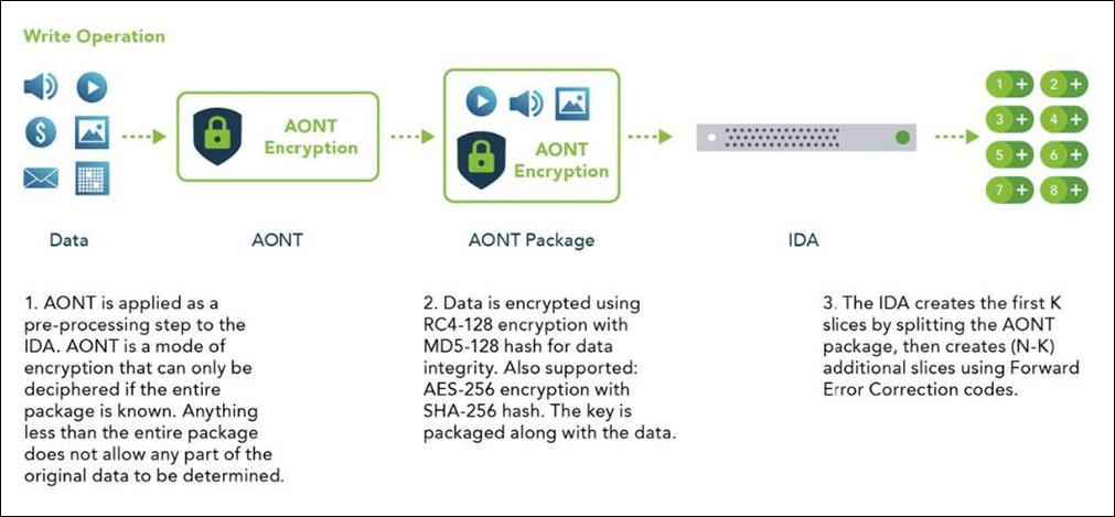
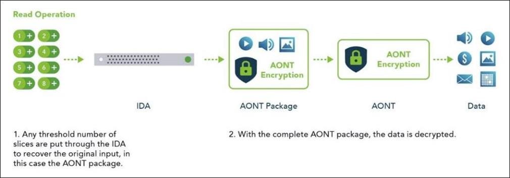
The IBM COS System storage technology uses Information Dispersal Algorithms (IDA) to separate data into unrecognizable “slices” that are distributed via network connections to storage nodes locally or across the world. The collection of dispersed storage appliances creates what is called a dispersed storage network. With dispersed storage technology, transmission and storage of data are inherently private and secure. No complete copy of the data exists in any single storage node. Only a subset of nodes needs to be available to fully retrieve the data on the network.
IDA technology transforms data into slices by using equations such that a subset of the slices can be used to re-create the original data. These slices, which are like packets but are for data storage, are then stored across multiple storage appliances (or storage nodes). Slices are created by using a combination of erasure coding, encryption, and sophisticated dispersal algorithms.
Dispersed storage systems are well-suited for storing unstructured data like digital media of all types, documents that are produced by desktop productivity applications, and server log files, which are typically larger files. Dispersal is not optimized for transaction-oriented primary storage for databases and similar high IOP workloads because of the extra processing associated with slicing and dispersing.
At a basic level, the IBM COS System platform uses three steps for slicing, dispersing, and retrieving data (Figure 15):
1. Data is virtualized, transformed, sliced, and dispersed by using IDAs. In the first figure, the data is separated into 12 slices. So the "width" (n) of the system is 12.
2. Slices are distributed to some combination of separate disks, storage nodes, and geographic locations. In this example, the slices are distributed to three different sites.
3. The data is retrieved from a subset of slices. In this example, the number of slices that are needed to retrieve the data is 8. So the "threshold" (k) of the system is 8.
Given a width of 12 and a threshold of 8, you can refer to this example as a "8 of 12" (k of n) configuration.
The configuration of a system is determined by the level of reliability needed. In a "8 of 12" configuration, four slices can be lost or unavailable and the data can still be retrieved because the threshold of seven slices is met. With a "5 of 8" configuration, only three slices can be lost, so the level of reliability is lower. Conversely, with a "20 of 32" configuration, 12 slices can be lost, so the level of reliability is higher.
Multi-site Failure
With dispersed storage, only a subset of slices is needed to retrieve the data. A dispersed storage system can tolerate appliance failures both within a single site and across multiple sites, as shown in the following figure.
1. Data is virtualized, transformed, sliced, and dispersed by using Information Dispersal Algorithm (IDAs). The "width" (n) of the system in this example is 12.
2. Slices are distributed to separate disks, storage nodes, and geographic locations. In this example, the slices are distributed to four geographically dispersed sites.
3. The data is retrieved from a subset of slices. In this example, the number of slices that are needed to retrieve the data is 8. So even though failures are occurring across all three sites, the data is still available to be retrieved because the "threshold" of seven available slices is reached.
Single-site, Multiple-device Failure
A dispersed storage system can also be deployed in a single site with the ability to tolerate the failure of multiple appliances within that site, as shown in the following figure.
1. Data is virtualized, transformed, sliced, and dispersed by using IDAs. The "width" (n) of the system in this example is 12.
2. Slices are distributed to separate disks, storage nodes, and geographic locations. In this example, the slices are distributed to four different racks within a single site.
3. The data is retrieved from a subset of slices. In this example, the number of slices that are needed to retrieve the data is 8. So even though each rack experienced one or more device failures, the data can be retrieved because the "threshold" of seven slices is met. Even with five slices unavailable, the data can be bit-perfectly recreated.
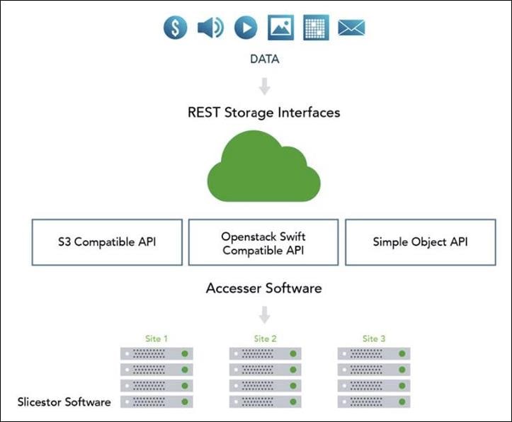
Cloud Object Storage Components
You can use the IBM COS System platform to create storage systems that have three software components: the IBM COS Manager, IBM COS Accesser, and IBM COS Slicestor .
The software components can be deployed on a wide range of compatible industry-standard hardware platforms, as virtual machines, and in the case of the IBM COS Accesser software, as a software application that is running on a Linux operating system. For example, a physical and virtual deployment can be combined in a single system by using virtual machine deployment for the IBM COS Manager and IBM COS Accesser and physical servers for the IBM COS Slicestor.
Each of the three software components serves a specific function:
· The IBM COS Manager is responsible for monitoring the health and performance of the system, configuring the system and provisioning storage, managing faults, and other administrative and operational functions.
· The IBM COS Accesser is responsible for encrypting/encoding data on ingest and decoding/decrypting it when read and managing the dispersal of slices of data resulting from this process across a set of IBM COS Slicestor nodes.
· The IBM COS Slicestor is responsible for the storage of slices.
The underlying storage pool of a dispersed or concentrated dispersed storage system can be shared and is jointly accessible by multiple access protocols.
When the IBM Cloud Object Storage Manager, IBM Cloud Object Storage Accesser, and IBM Cloud Object Storage Slicestor are deployed on a hardware platform that is certified by IBM®, the benefits are as follows:
· Minimum time to production on initial deployment because hardware and software compatibility and configuration are predefined and validated by IBM.
· Hardware configuration optimized to maximize value of the IBM Cloud Object Storage System.
· Increased system reliability due to low-level monitoring and management of hardware component health.
· Access to IBM support staff that are familiar with both the hardware and software components of the system.
Object-based Access Methods
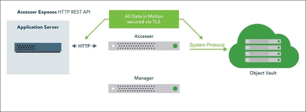
The Simple Object interface is accessed with a HTTP/REST API. Simple PUT, GET, DELETE, and LIST commands allow applications to access digital content, and the resulting object ID is stored directly within the application. With the IBM COS Accesser application, no IBM COS Accesser appliance is needed since the application server can talk directly to IBM COS Slicestor storage nodes.
REST API Access to Storage
REST is a style of software architecture for distributed hypermedia information retrieval systems such as the World Wide Web. REST-style architectures consist of clients and servers. Clients initiate requests to servers. Servers process requests and return associated responses. Requests and responses are built around the transfer of various representations of the resources.
The REST API works in way that is similar to retrieving a Universal Resource Locator (URL). But instead of requesting a webpage, the application is referencing an object.
REST API access to storage offers several advantages:
· Tolerates internet latency
· Provides for "programmable" storage
· Provides efficient global access to large amounts of data
Data Security
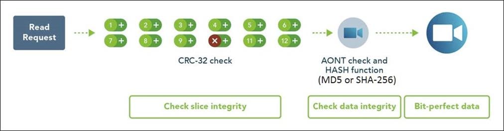
SecureSlice is the technology that is used to guarantee confidentiality, integrity, and availability of data stored on the system. SecureSlice combines two algorithms: An Information Dispersal Algorithm (IDA) and an All-or-Nothing Transform (AONT). AONT is a mode of encryption in which the information can be deciphered only if all the information is known. The diagrams illustrate basic write and read operations by using SecureSlice.
Network Security
All network traffic that is flowing into or out of appliances in a dispersed storage system is encrypted by using TLS with AES. Storage nodes can be placed anywhere without complex firewall or VPN setup, as shown in the following figure.
Availability Features
The availability features of a dispersed storage system provide continuous error detection and correction, ensuring bit-perfect data availability.
Integrity Check on All Slices and Files
A dispersed storage system checks for data integrity through an intelligent background process that proactively scans and corrects errors. It scans data slices for integrity, rebuilds any corrupted slices, and checks for both slice integrity and file data integrity before delivery. This process guarantees bit-perfect data delivery through proactive correction of bit errors and correction of latent soft errors that might occur during normal read/write operations. It also ensures that data cannot be modified without authorization and that malicious threats are detected.
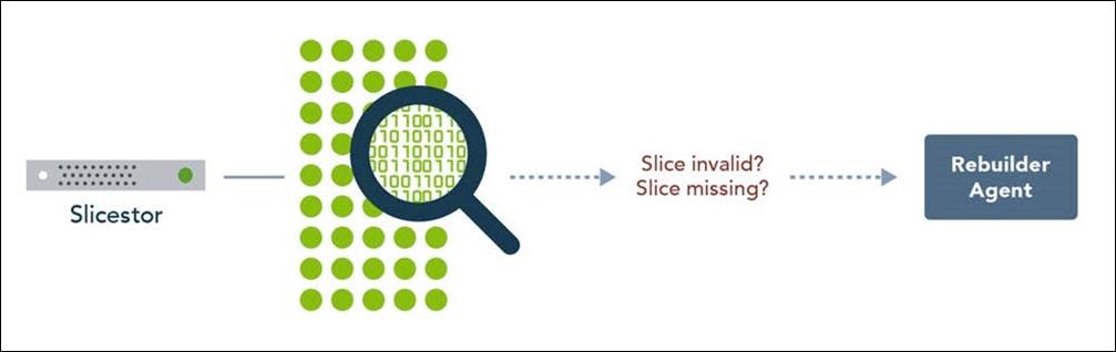
Continuous Error Correction
If a slice is determined to be corrupted, meaning that the integrity check value is invalid, the IBM Cloud Object Storage Slicestor appliance starts the distributed rebuilder technology to replace the slice with a valid slice. If the slice is missing, the distributed rebuilder technology recreates a valid slice. Continuous error correction increases system availability because it is not waiting for data to be read to detect errors. It is crucial with long-term archives and massive digital stores where information isn’t as frequently read. The distributed rebuilder model allows for predictability because the rebuilder is "always on" at a moderated rate, making I/O performance much more predictable, and scalable, as the rebuilder grows with storage.
Embedded Accesser
This CVD uses an Embedded Accesser Appliance function. The Embedded Accesser Appliance feature provides Accesser Appliance functions on the IBM COS Slicestor Appliance. This feature provides customers an opportunity to save on capital expenses by using one physical appliance for both Accesser and Slicestor appliance functions. However, before you deploy this feature, the following considerations need to be given to the Slicestor hardware and the workload presented to the servers and the load balancing between the available Slicestor appliances:
· Spread the load on all the available Embedded Accesser® Appliance.
· The performance degradation with Index ON cases might be more pronounced with Embedded Accesser® Appliance.
· There is some degree of performance degradation on all workloads with Embedded Accesser® Appliance.
· Workloads such as small file writes are more severely impacted than the others.
Network
Network administrators can configure the first four layers of the OSI model on a system to use separate network traffic between storage data, management information, and client data.
An IBM COS System that uses certified devices, can dedicate network interfaces (NICs) to three distinct networks to transfer:
· Data within the system
· Management information to management systems
· Data to a client application
These networks are referred to as channels.
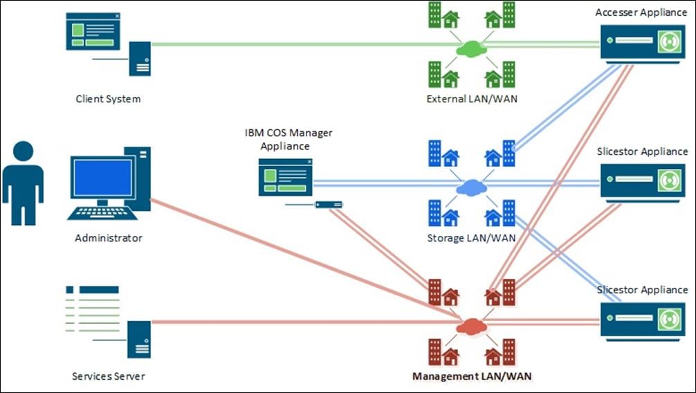
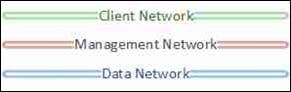
In separating data into channels, the system provides better security, more flexible management options and minimizes network congestion for high-performance applications.
Solution Overview
In this architecture, the CTERA Edge Filers are deployed on a Cisco Hyperflex Edge instance and CTERA Portal on Cisco HyperFlex standard cluster, using Cisco UCS S3260 M5 servers that provide unified storage and serve as the ideal platform for hosting IBM COS. The solution has six dual-node Cisco UCS S3260 M5 servers with IBM COS installed, which serves as capacity tier at the data center. In order to manage IBM COS and CTERA, we have the management portals hosted on a 4-node Cisco HyperFlex platform. This architecture aligns with the standardization of the HyperFlex platform as Hyper Converged Infrastructure (HCI) for the primary data center. For ROBO (Remote Office Branch Office) solution proposes Cisco HyperFlex Edge, a tailormade platform with two Cisco C220 M5 servers per ROBO to serve as the cache tier.
The IBM COS is configured with the Embedded Accessers which provides a modern S3 compatible application interface. The CTERA Portal is configured to use the S3 API to access the IBM COS solution. The CTERA Portal enables the access to the IBM COS Storage to remote offices via CTERA Edge Filers. Caching feature is enabled as a primary function in CTERA Edge Filers, which continuously sync the entire folder structure of the cloud portal to the Gateway devices and provides accelerated local access to the frequently accessed files.
This Cisco Validated Design provides a comprehensive, end-to-end guide for deploying CTERA on Cisco HyperFlex HX240c-M5SX and Cisco HyperFlex Edge HX-E-220M5SX together with IBM COS on Cisco UCS S3260 within infrastructure made possible by Cisco Intersight, Cisco UCS Manager, and the Cisco UCS 6454 Fabric Interconnects.
Each Cisco UCS S3260 M5 server relates to one 25-Gbps cable to each Cisco UCS Fabric Interconnect as well as each Cisco HX240c-M5SX HyperFlex System. The Cisco UCS HyperFlex system in the data center provides a standardized platform for all compute needs such as the CTERA Portal virtual machine and the IBM COS Manager virtual machine. IBM COS object storage is deployed on six Cisco UCS S3260 dual-node high capacity storage servers suited for petabyte-scale storage capabilities. Entire data center infrastructure is connected to a pair of Cisco UCS Fabric Interconnects and managed through Cisco UCS Manager, as shown in the Figure 26. The two node Cisco HyperFlex Edge systems use a 25-Gigabit Ethernet dual-switch configuration, as shown in Figure 27. One of the four 25-Gigabit Ethernet ports on the VIC 1455 network interface card (NIC) from each Cisco HX-E-220M5SX server is connected to the two top-of-rack (ToR) switches in the ROBO location. It is important to mention that 25-Gigabit Ethernet is not a must have for edge configuration. Cisco HyperFlex Edge systems can work with 10-Gigabit Ethernet architectures in the same way.
The usable storage capacity of IBM COS deployed on six Cisco UCS S3260 servers is 2240 TB, and that of four Cisco HyperFlex systems is 32.1 TB. The 2-node Cisco HyperFlex Edge deployed at each remote location has a usable storage capacity of 6 TB (Table 1).
| Storage Provider |
Capacity |
| IBM COS |
2,240 TB |
| Cisco HyperFlex Data Platform |
32.1 TB |
| Cisco HyperFlex Edge Site 1 |
6 TB |
| Cisco HyperFlex Edge Site 2 |
6 TB |
This solution doesn’t explain the WAN installation and configuration between a main datacenter and remote branch offices. For the simplicity we used one pair of Nexus switches and ran the remote branch offices in different VLANs to separate the traffic between all locations. Only the client VLAN 102 is configured for all locations.
Solution Flow
The solution setup consists of multiple parts. It explains basic setup of the network components, policies and profiles setup, installations of various parts as well as functional tests and high availability testing. The high-level flow of the solution setup is as follows:
1. Install and configure Cisco Nexus 93180YC-EX.
2. Install and configure Cisco UCS Fabric Interconnect 6454.
3. Configure and deploy policies and profiles for IBM Cloud Object Storage.
4. Deploy Cisco Intersight virtual Appliance.
5. Install and configure Cisco HyperFlex Data Platform cluster with Cisco Intersight.
6. Install and configure 2 x Cisco HyperFlex Edge cluster with Cisco Intersight.
7. Install and configure IBM Cloud Object Storage (not part of this CVD. However, for detailed information, see this CVD: https://www.cisco.com/c/en/us/td/docs/unified_compting/ucs/UCS_CVDs/versastack_ibmcos_s3260m5.pdf).
8. Install and configure CTERA Portal and CTERA Edge Filer.
9. Functional tests of the whole solution.
10. High Availability testing of the solution.
Requirements
The following sections detail the physical hardware, software revisions, and firmware versions required to install a single Cisco HyperFlex standard cluster, two Cisco HyperFlex Edge clusters, Cisco Intersight Virtual Appliance, the CTERA Edge Filer solution and IBM Cloud Object Storage. This is specific to the solution we built in this CVD. For more information regarding Cisco HyperFlex, Cisco HyperFlex Edge Design and Deployment, as well as IBM COS on Cisco UCS Design and Deployment, review the following CVDs:
· Cisco HyperFlex 4.0 for Virtual Server Infrastructure with VMware ESXi
· Cisco HyperFlex Edge 4.0 with Cisco Intersight
· VersaStack for IBM Cloud Object Storage on Cisco UCS S3260
Physical Components
Table 2 Hardware Components used in this CVD
| Component |
Model |
Quantity |
Comments |
| Switches |
Cisco Nexus 93180YC-EX |
2 |
|
| Cisco UCS Fabric Interconnects |
Cisco UCS 6454 Fabric Interconnects |
2 |
|
| Cisco HX Hyperconverged Infrastructure |
Cisco HX240c M5SX HyperFlex System |
4 |
Each Node: 2 x Intel Xeon Gold 6230 (2.1 GHz, 20 Cores) 384 GB Memory Cisco 12 Gbps Modular SAS HBA 1 x 240 GB M.2 6 Gbps SATA SSD for ESXi Hypervisor 1 x 240 GB 6 Gbps SATA SSD for System 1 x 1.6 TB Ent. Perf. 12 Gbps SAS SSD for Cache 12 x 2.4 TB 12 Gbps SAS HDD for Data 1 x VIC 1457 |
| Cisco HX Edge Hyperconverged Infrastructure |
Cisco HX220c M5SX HyperFlex System |
4 |
Each Node: 2 x Intel Xeon Silver 4216 (2.1 GHz, 16 Cores) 384 GB Memory Cisco 12 Gbps Modular SAS HBA 1 x 240 GB M.2 6 Gbps SATA SSD for ESXi Hypervisor 1 x 240 GB 6 Gbps SATA SSD for System 1 x 800 GB Ent. Perf. 12 Gbps SAS SSD for Cache 6 x 1.2 TB 12 Gbps SAS HDD for Data 1 x VIC 1457 |
| IBM Cloud Object Storage Slicestor/Accesser Node |
Cisco UCS S3260 M5 Chassis/Node |
6/12 |
Each Node: 2 x Intel Xeon Silver 4214 (2.2 GHz, 12 Cores) 384 GB Memory Dual RAID Controller 2 x 480 GB SATA SSD for OS 28 x 10 TB NL-SAS 7200 rpm 12 Gbps HDD for Data 1 x VIC 1455 |
| IBM Cloud Object Storage Manager |
Virtual Machine |
1 |
4 vCPU 16 GB Memory 128 GB Disk 1 x Network |
| CTERA Portal |
Virtual Machine |
1 |
2 vCPU 8 GB Memory 1 TB Disk 1 x Network |
| CTERA Edge Filer |
Virtual Machine |
2 |
Each VM: 4 vCPU 8 GB Memory 200 GB Disk 1 x Network |
Software Components
The required software distribution versions are listed in Table 3.
| Layer |
Component |
Version or Release |
| Cisco UCS S3260 Chassis |
Firmware Version |
4.1(1f) |
| Cisco UCS S3260 M5 Server |
Firmware Version |
4.1(1f) |
| Cisco HX240c-M5SX |
Cisco HyperFlex |
4.0(2b) |
| Firmware Version |
4.0(4k) |
|
| Cisco HX-E-220M5SX |
Cisco HyperFlex |
4.0(2b) |
| HUU Firmware Version |
4.0(4k) |
|
| Network 6454 Fabric Interconnect |
Cisco UCS Manager |
4.0(4h) |
| Kernel |
7.0(3)N2(4.04f) |
|
| System |
7.0(3)N2(4.04f) |
|
| Network Nexus 93180YC-EX |
BIOS |
07.67 |
| NXOS |
9.3(4) |
|
| Cisco Intersight Virtual Appliance |
Version |
1.0.9-149 |
| Software |
IBM COS |
3.14.11.39 |
| Software |
CTERA Portal CTERA Edge |
6.0.685 7.0.981 |
| Hypervisor |
VMware ESXi |
6.7 Update 3 |
| Management Server |
VMware vCenter |
6.7 Update 3 |
Physical Topology
Topology Overview
The solution contains two different topology configurations. The main datacenter configuration contains the heart of the whole solution – the hyperconverged infrastructure Cisco HyperFlex, hosting the CTERA Portal virtual machine and the IBM Cloud Object Manager virtual machine, building the capacity backbone for unstructured data. Figure 28 illustrates the details of the configuration.
Installing the HyperFlex system is done via the Cisco Intersight virtual appliance portal, or through a deployable HyperFlex installer virtual machine, available for download at cisco.com as an OVA file. Cisco Intersight performs most of the Cisco UCS configuration work and performs significant portions of the ESXi configuration. Finally, Cisco Intersight will install the HyperFlex HX Data Platform software and create the HyperFlex cluster. Because this simplified installation method has been developed by Cisco, this CVD will not give detailed manual steps for the configuration of all the elements that are handled by Cisco Intersight. Instead, the elements configured will be described and documented in this section, and the subsequent sections will guide you through the manual prerequisite steps needed for installation, and how to then utilize the HyperFlex Cisco Intersight Installer for the remaining configuration steps. This document focuses on the use of Cisco Intersight for the initial deployment of a Cisco HyperFlex cluster.
In addition to the Cisco HyperFlex installation via Cisco Intersight the document shows the process of installation and configuration of CTERA Portal on top of Cisco HyperFlex for the main data center.
The second topology configuration covers the remote branch offices and is identical for both locations in this CVD. Cisco HyperFlex Edge with CTERA Edge as a virtual machine is a perfect solution to stay remotely independent but still connect to the outside world, in our case the main datacenter. The details of the topology are shown in Figure 29.
The Cisco HyperFlex Edge cluster is built using Cisco HX-Series rack-mount servers without connecting them to Cisco UCS Fabric Interconnects. Upstream network connections, also referred to as “northbound” network connections, are made directly from the servers to the customer chosen data center top-of-rack (ToR) switches at the time of installation. With a minimum amount of hardware in a remote branch office, solutions can be deployed very easily.
Network Design
Cisco UCS Uplink Connectivity
Cisco UCS network uplinks connect “northbound” from the pair of Cisco UCS Fabric Interconnects to the LAN in the customer datacenter. All Cisco UCS uplinks operate as trunks, carrying multiple 802.1Q VLAN IDs across the uplinks. The default Cisco UCS behavior is to assume that all VLAN IDs defined in the Cisco UCS configuration are eligible to be trunked across all available uplinks.
Cisco UCS Fabric Interconnects appear on the network as a collection of endpoints versus another network switch. Internally, the Fabric Interconnects do not participate in spanning-tree protocol (STP) domains, and the Fabric Interconnects cannot form a network loop, as they are not connected to each other with a layer 2 Ethernet link. All link up/down decisions via STP will be made by the upstream root bridges.
Uplinks need to be connected and active from both Fabric Interconnects. For redundancy, multiple uplinks can be used on each FI, either as 802.3ad Link Aggregation Control Protocol (LACP) port-channels or using individual links. For the best level of performance and redundancy, uplinks can be made as LACP port-channels to multiple upstream Cisco switches using the virtual port channel (vPC) feature. Using vPC uplinks allows all uplinks to be active passing data, plus protects against any individual link failure, and the failure of an upstream switch. Other uplink configurations can be redundant, however spanning-tree protocol loop avoidance may disable links if vPC is not available.
All uplink connectivity methods must allow for traffic to pass from one Fabric Interconnect to the other, or from fabric A to fabric B. There are scenarios where cable, port or link failures would require traffic that normally does not leave the Cisco UCS domain, to instead be directed over the Cisco UCS uplinks because that traffic must travel from fabric A to fabric B, or vice-versa. Additionally, this traffic flow pattern can be seen briefly during maintenance procedures, such as updating firmware on the Fabric Interconnects, which requires them to be rebooted. Cisco recommends that the uplink bandwidth configured is greater than or equal to double the bandwidth available to each Hyperflex converged node. For example, if the nodes are connected at 25 Gigabit speeds, then each Fabric Interconnect should have at least 50 Gigabit of uplink bandwidth available. This configuration uses 4 x 40 Gigabit uplink speed for the ToR switches because of the additional scale-out storage platform IBM COS, which is used as a tiered storage solution.
vPC to Multiple Switches
This recommended connection design relies on using Cisco switches that have the virtual port channel feature, such as Cisco Nexus 9000 series switches. Logically the two vPC enabled switches appear as one, and therefore spanning-tree protocol will not block any links. This configuration allows for all links to be active, achieving maximum bandwidth potential, and multiple redundancy at each level.
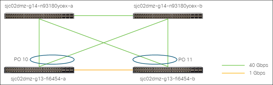
Use Table 4 to gather the required network uplink information for the installation and list the information used in this CVD:
Table 4 Network Uplink Configuration
| Fabric Interconnect Port |
Port Channel |
Port Channel Type |
Port Channel ID |
Port Channel Name |
|
| sjc02dmz-g13-fi6454-a |
1/49 |
S Yes £ No |
S vPC £ LACP |
10 |
vpc-10 |
| 1/50 |
S Yes £ No |
S vPC £ LACP |
|||
| 1/51 |
S Yes £ No |
S vPC £ LACP |
|||
| 1/52 |
S Yes £ No |
S vPC £ LACP |
|||
| sjc02dmz-g13-fi6454-b |
1/49 |
S Yes £ No |
S vPC £ LACP |
11 |
vpc-11 |
| 1/50 |
S Yes £ No |
S vPC £ LACP |
|||
| 1/51 |
S Yes £ No |
S vPC £ LACP |
|||
| 1/52 |
S Yes £ No |
S vPC £ LACP |
|||
VLANs and Subnets
For the base HyperFlex and HyperFlex Edge system configuration as well as the IBM Cloud Object Storage configuration, multiple VLANs need to be carried to the Cisco UCS domain from the upstream LAN, and these VLANs are also defined in the Cisco UCS configuration. Table 5 lists the VLANs created by the Cisco Intersight and Cisco UCS Manager used in this CVD and their functions:
| VLAN Name |
VLAN ID |
Subnet |
Purpose |
| Management |
100 |
172.16.0.0/24 GW 172.16.0.1 |
ESXi host management interfaces (HX Data Platform) HX Storage Controller VM management interfaces (HX Data Platform) Cisco UCS CIMC management interfaces Cisco UCS Fabric Interconnect management interfaces |
| Data/Storage |
101 |
172.16.1.0/24 GW 172.16.1.1 |
ESXi host storage VMkernel interfaces (HX Data Platform) HX Storage Controller storage network interfaces (HX Data Platform) IBM COS data channel |
| Client |
102 |
172.16.2.0/24 GW 172.16.2.1 |
CTERA Portal and CTERA Edge Filer client interface IBM COS client channel |
| vMotion |
103 |
172.16.3.0/24 GW 172.16.3.1 |
ESXi host vMotion VMkernel interfaces (HX Data Platform) |
| VMNetwork |
104 |
172.16.4.0/24 GW 172.16.4.1 |
Guest VM network interfaces |
| ROBO1-Management |
105 |
172.16.5.0/24 GW 172.16.5.1 |
ESXi host management interfaces (HX Edge Location 1) HX Storage Controller VM management interfaces (HX Edge Location 1) |
| ROBO1-Storage |
106 |
172.16.6.0/24 GW 172.16.6.1 |
ESXi host storage VMkernel interfaces (HX Edge Location 1) HX Storage Controller storage network interfaces (HX Edge Location 1) |
| ROBO1-vMotion |
107 |
172.16.7.0/24 GW 172.16.7.1 |
ESXi host vMotion VMkernel interfaces (HX Edge Location 1) |
| ROBO2-Management |
108 |
172.16.8.0/24 GW 172.16.8.1 |
ESXi host management interfaces (HX Edge Location 2) HX Storage Controller VM management interfaces (HX Edge Location 2) |
| ROBO2-Storage |
109 |
172.16.9.0/24 GW 172.16.9.1 |
ESXi host storage VMkernel interfaces (HX Edge Location 2) HX Storage Controller storage network interfaces (HX Edge Location 2) |
| ROBO2-vMotion |
110 |
172.16.10.0/24 GW 172.16.10.1 |
ESXi host vMotion VMkernel interfaces (HX Edge Location 2) |
Jumbo Frames
All HyperFlex storage traffic traversing the Data/Storage VLAN and subnet is configured by default to use jumbo frames, or to be precise, all communication is configured to send IP packets with a Maximum Transmission Unit (MTU) size of 9000 bytes. In addition, the default MTU for the vMotion VLAN is also set to use jumbo frames. Using a larger MTU value means that each IP packet sent carries a larger payload, therefore transmitting more data per packet, and consequently sending and receiving data faster. This configuration also means that the Cisco UCS uplinks must be configured to pass jumbo frames. Failure to configure the Cisco UCS uplink switches to allow jumbo frames can lead to service interruptions during some failure scenarios, including Cisco UCS firmware upgrades, or when a cable or port failure would cause storage traffic to traverse the northbound Cisco UCS uplink switches.
HyperFlex clusters can be configured to use standard size frames of 1500 bytes, however Cisco recommends that this configuration only be used in environments where the Cisco UCS uplink switches are not capable of passing jumbo frames, and that jumbo frames be enabled in all other situations.
Naming Scheme and DNS
DNS servers are highly recommended to be configured for querying Fully Qualified Domain Names (FQDN) in the HyperFlex and ESXi Management group. DNS records need to be created prior to beginning the installation. At a minimum, it is highly recommended to create A records and reverse PTR records for the ESXi hypervisor hosts’ management interfaces. Additional DNS A records can be created for the Storage Controller Management interfaces, ESXi Hypervisor Storage interfaces, and the Storage Controller Storage interfaces if desired.
Use Table 6 to gather the required DNS information for the installation and list the information required for this CVD:
Table 6 DNS Server Information
| Item |
Name |
| DNS Server |
192.168.10.51 |
| DNS Domain |
sjc02dmz.net |
| vCenter Server Name |
sjc02dmz-vcsa |
| Cisco Nexus 93180YC-EX #1 |
sjc02dmz-g14-n93180ycex-a |
| Cisco Nexus 93180YC-EX #2 |
sjc02dmz-g14-n93180ycex-b |
| Cisco UCS Fabric Interconnect #1 |
sjc02dmz-g13-fi6454-a |
| Cisco UCS Fabric Interconnect #2 |
sjc02dmz-g13-fi6454-b |
| Cisco UCS Manager |
sjc02dmz-g13-ucsm |
| Cisco Intersight virtual Appliance |
sjc02dmz-intersight |
| Cisco HX Server #1 |
sjc02dmz-g14-hx240c-1 |
| Cisco HX Server #2 |
sjc02dmz-g14-hx240c-2 |
| Cisco HX Server #3 |
sjc02dmz-g14-hx240c-3 |
| Cisco HX Server #4 |
sjc02dmz-g14-hx240c-4 |
| Cisco HX Edge Server #1 Location 1 |
sjc02dmz-g14-hxe-1 |
| Cisco HX Edge Server #2 Location 1 |
sjc02dmz-g14-hxe-2 |
| Cisco HX Edge Server #1 Location 2 |
sjc02dmz-g14-hxe-3 |
| Cisco HX Edge Server #2 Location 2 |
sjc02dmz-g14-hxe-4 |
| CTERA Portal |
sjc02dmz-ctera-portal |
| CTERA Edge Location 1 |
sjc02dmz-ctera-edge1 |
| CTERA Edge Location 2 |
sjc02dmz-ctera-edge2 |
| IBM COS Slicestor #1 |
sjc02dmz-g13-slicestor1 |
| IBM COS Slicestor #2 |
sjc02dmz-g13-slicestor2 |
| IBM COS Slicestor #3 |
sjc02dmz-g13-slicestor3 |
| IBM COS Slicestor #4 |
sjc02dmz-g13-slicestor4 |
| IBM COS Slicestor #5 |
sjc02dmz-g13-slicestor5 |
| IBM COS Slicestor #6 |
sjc02dmz-g13-slicestor6 |
| IBM COS Slicestor #7 |
sjc02dmz-g13-slicestor7 |
| IBM COS Slicestor #8 |
sjc02dmz-g13-slicestor8 |
| IBM COS Slicestor #9 |
sjc02dmz-g13-slicestor9 |
| IBM COS Slicestor #10 |
sjc02dmz-g13-slicestor10 |
| IBM COS Slicestor #11 |
sjc02dmz-g13-slicestor11 |
| IBM COS Slicestor #12 |
sjc02dmz-g13-slicestor12 |
Cabling
The physical layout of the solution was previously described in section Topology Overview. The Fabric Interconnects, HX-series rack-mount servers, Cisco UCS S3260 chassis and nodes need to be cabled properly before beginning the installation activities. Tables 7 and Table 8 provide the cabling map for installation of a Cisco HyperFlex standard cluster with four HyperFlex converged servers, two HyperFlex Edge clusters with two HyperFlex Edge nodes and six Cisco UCS S3260 chassis with twelve nodes.
Table 7 Cabling Map Cisco Nexus 93180YC-EX
| Device |
Port |
Connected To |
Port |
Note |
| sjc02dmz-g14-n93180ycex-a |
17 |
sjc02dmz-g14-hxe-1 |
mLOM port 1 |
|
| sjc02dmz-g14-n93180ycex-a |
18 |
sjc02dmz-g14-hxe-2 |
mLOM port 1 |
|
| sjc02dmz-g14-n93180ycex-a |
19 |
sjc02dmz-g14-hxe-3 |
mLOM port 1 |
|
| sjc02dmz-g14-n93180ycex-a |
20 |
sjc02dmz-g14-hxe-4 |
mLOM port 1 |
|
| sjc02dmz-g14-n93180ycex-a |
27 |
sjc02dmz-g13-fi6454-a |
mgmt0 |
|
| sjc02dmz-g14-n93180ycex-a |
29 |
sjc02dmz-g13-fi6454-b |
mgmt0 |
|
| sjc02dmz-g14-n93180ycex-a |
49 |
sjc02dmz-g14-n93180ycex-b |
Eth1/49 |
vPC Peer Link |
| sjc02dmz-g14-n93180ycex-a |
50 |
sjc02dmz-g14-n93180ycex-b |
Eth1/50 |
vPC Peer Link |
| sjc02dmz-g14-n93180ycex-a |
51 |
sjc02dmz-g13-fi6454-a |
Eth1/51 |
Po10 |
| sjc02dmz-g14-n93180ycex-a |
52 |
sjc02dmz-g13-fi6454-a |
Eth1/52 |
Po10 |
| sjc02dmz-g14-n93180ycex-a |
53 |
sjc02dmz-g13-fi6454-b |
Eth1/51 |
Po11 |
| sjc02dmz-g14-n93180ycex-a |
54 |
sjc02dmz-g13-fi6454-b |
Eth1/52 |
Po11 |
| Device |
Port |
Connected To |
Port |
Note |
| sjc02dmz-g14-n93180ycex-b |
17 |
sjc02dmz-g14-hxe-1 |
mLOM port 3 |
|
| sjc02dmz-g14-n93180ycex-b |
18 |
sjc02dmz-g14-hxe-2 |
mLOM port 3 |
|
| sjc02dmz-g14-n93180ycex-b |
19 |
sjc02dmz-g14-hxe-3 |
mLOM port 3 |
|
| sjc02dmz-g14-n93180ycex-b |
20 |
sjc02dmz-g14-hxe-4 |
mLOM port 3 |
|
| sjc02dmz-g14-n93180ycex-b |
49 |
sjc02dmz-g14-n93180ycex-a |
Eth1/49 |
vPC Peer Link |
| sjc02dmz-g14-n93180ycex-b |
50 |
sjc02dmz-g14-n93180ycex-a |
Eth1/50 |
vPC Peer Link |
| sjc02dmz-g14-n93180ycex-b |
51 |
sjc02dmz-g13-fi6454-a |
Eth1/49 |
Po10 |
| sjc02dmz-g14-n93180ycex-b |
52 |
sjc02dmz-g13-fi6454-a |
Eth1/50 |
Po10 |
| sjc02dmz-g14-n93180ycex-b |
53 |
sjc02dmz-g13-fi6454-b |
Eth1/49 |
Po11 |
| sjc02dmz-g14-n93180ycex-b |
54 |
sjc02dmz-g13-fi6454-b |
Eth1/50 |
Po11 |
Table 8 Cabling Map Cisco Fabric Interconnect 6454
| Device |
Port |
Connected To |
Port |
Note |
| sjc02dmz-g14-fi6454-a |
L1 |
sjc02dmz-g14-fi6454-b |
L1 |
|
| sjc02dmz-g14-fi6454-a |
L2 |
sjc02dmz-g14-fi6454-b |
L2 |
|
| sjc02dmz-g14-fi6454-a |
mgmt0 |
sjc02dmz-g14-n93180ycex-a |
Eth1/27 |
|
| sjc02dmz-g14-fi6454-a |
1 |
sjc02dmz-g14-slicestor1 |
mLOM port 1 |
|
| sjc02dmz-g14-fi6454-a |
2 |
sjc02dmz-g14-slicestor2 |
mLOM port 1 |
|
| sjc02dmz-g14-fi6454-a |
3 |
sjc02dmz-g14-slicestor3 |
mLOM port 1 |
|
| sjc02dmz-g14-fi6454-a |
4 |
sjc02dmz-g14-slicestor4 |
mLOM port 1 |
|
| sjc02dmz-g14-fi6454-a |
5 |
sjc02dmz-g14-slicestor5 |
mLOM port 1 |
|
| sjc02dmz-g14-fi6454-a |
6 |
sjc02dmz-g14-slicestor6 |
mLOM port 1 |
|
| sjc02dmz-g14-fi6454-a |
7 |
sjc02dmz-g14-slicestor7 |
mLOM port 1 |
|
| sjc02dmz-g14-fi6454-a |
8 |
sjc02dmz-g14-slicestor8 |
mLOM port 1 |
|
| sjc02dmz-g14-fi6454-a |
9 |
sjc02dmz-g14-slicestor9 |
mLOM port 1 |
|
| sjc02dmz-g14-fi6454-a |
10 |
sjc02dmz-g14-slicestor10 |
mLOM port 1 |
|
| sjc02dmz-g14-fi6454-a |
11 |
sjc02dmz-g14-slicestor11 |
mLOM port 1 |
|
| sjc02dmz-g14-fi6454-a |
12 |
sjc02dmz-g14-slicestor12 |
mLOM port 1 |
|
| sjc02dmz-g14-fi6454-a |
13 |
sjc02dmz-g14-hx240c-1 |
mLOM port 1 |
|
| sjc02dmz-g14-fi6454-a |
14 |
sjc02dmz-g14-hx240c-2 |
mLOM port 1 |
|
| sjc02dmz-g14-fi6454-a |
15 |
sjc02dmz-g14-hx240c-3 |
mLOM port 1 |
|
| sjc02dmz-g14-fi6454-a |
16 |
sjc02dmz-g14-hx240c-4 |
mLOM port 1 |
|
| sjc02dmz-g14-fi6454-a |
49 |
sjc02dmz-g14-n93180ycex-a |
Eth1/51 |
Po10 |
| sjc02dmz-g14-fi6454-a |
50 |
sjc02dmz-g14-n93180ycex-a |
Eth1/52 |
Po10 |
| sjc02dmz-g14-fi6454-a |
51 |
sjc02dmz-g14-n93180ycex-b |
Eth1/51 |
Po10 |
| sjc02dmz-g14-fi6454-a |
52 |
sjc02dmz-g14-n93180ycex-b |
Eth1/52 |
Po10 |
| Device |
Port |
Connected To |
Port |
Note |
| sjc02dmz-g14-fi6454-b |
L1 |
sjc02dmz-g14-fi6454-a |
L1 |
|
| sjc02dmz-g14-fi6454-b |
L2 |
sjc02dmz-g14-fi6454-a |
L2 |
|
| sjc02dmz-g14-fi6454-b |
mgmt0 |
sjc02dmz-g14-n93180ycex-a |
Eth1/29 |
|
| sjc02dmz-g14-fi6454-b |
1 |
sjc02dmz-g14-slicestor1 |
mLOM port 3 |
|
| sjc02dmz-g14-fi6454-b |
2 |
sjc02dmz-g14-slicestor2 |
mLOM port 3 |
|
| sjc02dmz-g14-fi6454-b |
3 |
sjc02dmz-g14-slicestor3 |
mLOM port 3 |
|
| sjc02dmz-g14-fi6454-b |
4 |
sjc02dmz-g14-slicestor4 |
mLOM port 3 |
|
| sjc02dmz-g14-fi6454-b |
5 |
sjc02dmz-g14-slicestor5 |
mLOM port 3 |
|
| sjc02dmz-g14-fi6454-b |
6 |
sjc02dmz-g14-slicestor6 |
mLOM port 3 |
|
| sjc02dmz-g14-fi6454-b |
7 |
sjc02dmz-g14-slicestor7 |
mLOM port 3 |
|
| sjc02dmz-g14-fi6454-b |
8 |
sjc02dmz-g14-slicestor8 |
mLOM port 3 |
|
| sjc02dmz-g14-fi6454-b |
9 |
sjc02dmz-g14-slicestor9 |
mLOM port 3 |
|
| sjc02dmz-g14-fi6454-b |
10 |
sjc02dmz-g14-slicestor10 |
mLOM port 3 |
|
| sjc02dmz-g14-fi6454-b |
11 |
sjc02dmz-g14-slicestor11 |
mLOM port 3 |
|
| sjc02dmz-g14-fi6454-b |
12 |
sjc02dmz-g14-slicestor12 |
mLOM port 3 |
|
| sjc02dmz-g14-fi6454-b |
13 |
sjc02dmz-g14-hx240c-1 |
mLOM port 3 |
|
| sjc02dmz-g14-fi6454-b |
14 |
sjc02dmz-g14-hx240c-2 |
mLOM port 3 |
|
| sjc02dmz-g14-fi6454-b |
15 |
sjc02dmz-g14-hx240c-3 |
mLOM port 3 |
|
| sjc02dmz-g14-fi6454-b |
16 |
sjc02dmz-g14-hx240c-4 |
mLOM port 3 |
|
| sjc02dmz-g14-fi6454-b |
49 |
sjc02dmz-g14-n93180ycex-b |
Eth1/53 |
Po11 |
| sjc02dmz-g14-fi6454-b |
50 |
sjc02dmz-g14-n93180ycex-b |
Eth1/54 |
Po11 |
| sjc02dmz-g14-fi6454-b |
51 |
sjc02dmz-g14-n93180ycex-a |
Eth1/53 |
Po11 |
| sjc02dmz-g14-fi6454-b |
52 |
sjc02dmz-g14-n93180ycex-a |
Eth1/54 |
Po11 |
Fabric Configuration
This section provides the details to configure a fully redundant, highly available Cisco UCS 6454 fabric configuration.
Configure Cisco Nexus 93180YC-EX Switch A and B
Both Cisco UCS Fabric Interconnect A and B are connected to two Cisco Nexus 93180YC-EX switches for connectivity to applications and clients. The following sections describe the setup of both Cisco Nexus 93180YC-EX switches.
Initial Setup of Cisco Nexus 93180YC-EX Switch A and B
To configure Switch A, connect a Console to the Console port of each switch, power on the switch and follow these steps:
1. Type yes.
2. Type n.
3. Type n.
4. Type n.
5. Enter the switch name.
6. Type y.
7. Type your IPv4 management address for Switch A.
8. Type your IPv4 management netmask for Switch A.
9. Type y.
10. Type your IPv4 management default gateway address for Switch A.
11. Type n.
12. Type n.
13. Type y for ssh service.
14. Press <Return> and then <Return>.
15. Type y for ntp server.
16. Type the IPv4 address of the NTP server.
17. Type in L2 for interface layer.
18. Press <Return> and again <Return>.
19. Check the configuration and if correct then press <Return> and again <Return>.
The complete setup looks like the following:
---- System Admin Account Setup ----
Do you want to enforce secure password standard (yes/no) [y]:
Enter the password for "admin":
Confirm the password for "admin":
---- Basic System Configuration Dialog VDC: 1 ----
This setup utility will guide you through the basic configuration of
the system. Setup configures only enough connectivity for management
of the system.
Please register Cisco Nexus9000 Family devices promptly with your
supplier. Failure to register may affect response times for initial
service calls. Nexus9000 devices must be registered to receive
entitled support services.
Press Enter at anytime to skip a dialog. Use ctrl-c at anytime
to skip the remaining dialogs.
Would you like to enter the basic configuration dialog (yes/no): yes
Create another login account (yes/no) [n]:
Configure read-only SNMP community string (yes/no) [n]:
Configure read-write SNMP community string (yes/no) [n]:
Enter the switch name : SJC02DMZ-G14-N93180YC-EX-A
Continue with Out-of-band (mgmt0) management configuration? (yes/no) [y]:
Mgmt0 IPv4 address : 172.16.0.4
Mgmt0 IPv4 netmask : 255.255.255.0
Configure the default gateway? (yes/no) [y]:
IPv4 address of the default gateway : 192.168.11.3
Configure advanced IP options? (yes/no) [n]:
Enable the telnet service? (yes/no) [n]:
Enable the ssh service? (yes/no) [y]:
Type of ssh key you would like to generate (dsa/rsa) [rsa]:
Number of rsa key bits <1024-2048> [1024]:
Configure the ntp server? (yes/no) [n]: y
NTP server IPv4 address : 173.38.201.115
Configure default interface layer (L3/L2) [L3]: L2
Configure default switchport interface state (shut/noshut) [shut]:
Configure CoPP system profile (strict/moderate/lenient/dense) [strict]:
The following configuration will be applied:
password strength-check
switchname SJC02DMZ-G14-N93180YC-EX-A
vrf context management
ip route 0.0.0.0/0 192.168.11.3
exit
no feature telnet
ssh key rsa 1024 force
feature ssh
ntp server 173.38.201.115
no system default switchport
system default switchport shutdown
copp profile strict
interface mgmt0
ip address 172.16.0.4 255.255.255.0
no shutdown
Would you like to edit the configuration? (yes/no) [n]:
Use this configuration and save it? (yes/no) [y]:
[########################################] 100%
Copy complete.
User Access Verification
SJC02DMZ-G14-N93180YC-EX-A login:
![]() Repeat steps 1-19 for the Cisco Nexus 93180YC-EX Switch B with the exception of configuring a different IPv4 management address in step 7.
Repeat steps 1-19 for the Cisco Nexus 93180YC-EX Switch B with the exception of configuring a different IPv4 management address in step 7.
Enable Features on Cisco Nexus 93180YC-EX Switch A and B
To enable the features UDLD, VLAN, LACP, HSRP, VPC, and Jumbo Frames, connect to the management interface via ssh on both switches and follow these steps on both Switch A and B:
Switch A
SJC02DMZ-G14-N93180YC-EX-A # configure terminal
Enter configuration commands, one per line. End with CNTL/Z.
SJC02DMZ-G14-N93180YC-EX-A (config)# feature udld
SJC02DMZ-G14-N93180YC-EX-A (config)# feature interface-vlan
SJC02DMZ-G14-N93180YC-EX-A(config)# feature lacp
SJC02DMZ-G14-N93180YC-EX-A(config)# feature vpc
SJC02DMZ-G14-N93180YC-EX-A(config)# feature hsrp
SJC02DMZ-G14-N93180YC-EX-A(config)# system jumbomtu 9216
SJC02DMZ-G14-N93180YC-EX-A(config)# spanning-tree port type edge bpduguard default
SJC02DMZ-G14-N93180YC-EX-A(config)# spanning-tree port type edge bpdufilter default
SJC02DMZ-G14-N93180YC-EX-A(config)# port-channel load-balance src-dst ip-l4port-vlan
SJC02DMZ-G14-N93180YC-EX-A(config)# exit
SJC02DMZ-G14-N93180YC-EX-A#
Switch B
SJC02DMZ-G14-N93180YC-EX-B# configure terminal
Enter configuration commands, one per line. End with CNTL/Z.
SJC02DMZ-G14-N93180YC-EX-B(config)# feature udld
SJC02DMZ-G14-N93180YC-EX-B(config)# feature interface-vlan
SJC02DMZ-G14-N93180YC-EX-B(config)# feature lacp
SJC02DMZ-G14-N93180YC-EX-B(config)# feature vpc
SJC02DMZ-G14-N93180YC-EX-A(config)# feature hsrp
SJC02DMZ-G14-N93180YC-EX-B(config)# system jumbomtu 9216
SJC02DMZ-G14-N93180YC-EX-B(config)# spanning-tree port type edge bpduguard default
SJC02DMZ-G14-N93180YC-EX-B(config)# spanning-tree port type edge bpdufilter default
SJC02DMZ-G14-N93180YC-EX-B(config)# port-channel load-balance src-dst ip-l4port-vlan
SJC02DMZ-G14-N93180YC-EX-B(config)# exit
SJC02DMZ-G14-N93180YC-EX-B#
Configure VLANs on Cisco Nexus 93180YC-EX Switch A and B
To configure VLAN Native-VLAN and Public-VLAN, follow these steps on Switch A and Switch B:
Switch A
SJC02DMZ-G14-N93180YC-EX-A# config terminal
Enter configuration commands, one per line. End with CNTL/Z.
SJC02DMZ-G14-N93180YC-EX-A(config)# vlan 100
SJC02DMZ-G14-N93180YC-EX-A(config-vlan)# name Management
SJC02DMZ-G14-N93180YC-EX-A(config-vlan)# exit
SJC02DMZ-G14-N93180YC-EX-A(config)# vlan 101
SJC02DMZ-G14-N93180YC-EX-A(config-vlan)# name Data/Storage
SJC02DMZ-G14-N93180YC-EX-A(config-vlan)# exit
SJC02DMZ-G14-N93180YC-EX-A(config)# vlan 102
SJC02DMZ-G14-N93180YC-EX-A(config-vlan)# name Client
SJC02DMZ-G14-N93180YC-EX-A(config-vlan)# exit
SJC02DMZ-G14-N93180YC-EX-A(config)# vlan 103
SJC02DMZ-G14-N93180YC-EX-A(config-vlan)# name vMotion
SJC02DMZ-G14-N93180YC-EX-A(config-vlan)# exit
SJC02DMZ-G14-N93180YC-EX-A(config)# vlan 104
SJC02DMZ-G14-N93180YC-EX-A(config-vlan)# name VMNetwork
SJC02DMZ-G14-N93180YC-EX-A(config-vlan)# exit
SJC02DMZ-G14-N93180YC-EX-A(config)# vlan 105
SJC02DMZ-G14-N93180YC-EX-A(config-vlan)# name ROBO1-Management
SJC02DMZ-G14-N93180YC-EX-A(config-vlan)# exit
SJC02DMZ-G14-N93180YC-EX-A(config)# vlan 106
SJC02DMZ-G14-N93180YC-EX-A(config-vlan)# name ROBO1-Storage
SJC02DMZ-G14-N93180YC-EX-A(config-vlan)# exit
SJC02DMZ-G14-N93180YC-EX-A(config)# vlan 107
SJC02DMZ-G14-N93180YC-EX-A(config-vlan)# name ROBO1-vMotion
SJC02DMZ-G14-N93180YC-EX-A(config-vlan)# exit
SJC02DMZ-G14-N93180YC-EX-A(config)# vlan 108
SJC02DMZ-G14-N93180YC-EX-A(config-vlan)# name ROBO2-Management
SJC02DMZ-G14-N93180YC-EX-A(config-vlan)# exit
SJC02DMZ-G14-N93180YC-EX-A(config)# vlan 109
SJC02DMZ-G14-N93180YC-EX-A(config-vlan)# name ROBO2-Storage
SJC02DMZ-G14-N93180YC-EX-A(config-vlan)# exit
SJC02DMZ-G14-N93180YC-EX-A(config)# vlan 110
SJC02DMZ-G14-N93180YC-EX-A(config-vlan)# name ROBO2-vMotion
SJC02DMZ-G14-N93180YC-EX-A(config)#interface vlan 100
SJC02DMZ-G14-N93180YC-EX-A(config-if)# no shut
SJC02DMZ-G14-N93180YC-EX-A(config-if)# mtu 9216
SJC02DMZ-G14-N93180YC-EX-A(config-if)# no ip redirects
SJC02DMZ-G14-N93180YC-EX-A(config-if)# ip address 172.16.0.2/24
SJC02DMZ-G14-N93180YC-EX-A(config-if)# no ipv6 redirects
SJC02DMZ-G14-N93180YC-EX-A(config-if)# hsrp version 2
SJC02DMZ-G14-N93180YC-EX-A(config-if)# hsrp 101
SJC02DMZ-G14-N93180YC-EX-A(config-if-hsrp)# preempt delay minimum 300
SJC02DMZ-G14-N93180YC-EX-A(config-if-hsrp)# priority 110
SJC02DMZ-G14-N93180YC-EX-A(config-if-hsrp)# ip 172.16.0.1
SJC02DMZ-G14-N93180YC-EX-A(config-if-hsrp)# exit
SJC02DMZ-G14-N93180YC-EX-A(config-if)# exit
SJC02DMZ-G14-N93180YC-EX-A(config)#interface vlan 101
SJC02DMZ-G14-N93180YC-EX-A(config-if)# no shut
SJC02DMZ-G14-N93180YC-EX-A(config-if)# mtu 9216
SJC02DMZ-G14-N93180YC-EX-A(config-if)# no ip redirects
SJC02DMZ-G14-N93180YC-EX-A(config-if)# ip address 172.16.1.2/24
SJC02DMZ-G14-N93180YC-EX-A(config-if)# no ipv6 redirects
SJC02DMZ-G14-N93180YC-EX-A(config-if)# hsrp version 2
SJC02DMZ-G14-N93180YC-EX-A(config-if)# hsrp 101
SJC02DMZ-G14-N93180YC-EX-A(config-if-hsrp)# preempt delay minimum 300
SJC02DMZ-G14-N93180YC-EX-A(config-if-hsrp)# priority 110
SJC02DMZ-G14-N93180YC-EX-A(config-if-hsrp)# ip 172.16.1.1
SJC02DMZ-G14-N93180YC-EX-A(config-if-hsrp)# exit
SJC02DMZ-G14-N93180YC-EX-A(config-if)# exit
SJC02DMZ-G14-N93180YC-EX-A(config)#interface vlan 102
SJC02DMZ-G14-N93180YC-EX-A(config-if)# no shut
SJC02DMZ-G14-N93180YC-EX-A(config-if)# mtu 9216
SJC02DMZ-G14-N93180YC-EX-A(config-if)# no ip redirects
SJC02DMZ-G14-N93180YC-EX-A(config-if)# ip address 172.16.2.2/24
SJC02DMZ-G14-N93180YC-EX-A(config-if)# no ipv6 redirects
SJC02DMZ-G14-N93180YC-EX-A(config-if)# hsrp version 2
SJC02DMZ-G14-N93180YC-EX-A(config-if)# hsrp 102
SJC02DMZ-G14-N93180YC-EX-A(config-if-hsrp)# preempt delay minimum 300
SJC02DMZ-G14-N93180YC-EX-A(config-if-hsrp)# priority 110
SJC02DMZ-G14-N93180YC-EX-A(config-if-hsrp)# ip 172.16.2.1
SJC02DMZ-G14-N93180YC-EX-A(config-if-hsrp)# exit
SJC02DMZ-G14-N93180YC-EX-A(config-if)# exit
SJC02DMZ-G14-N93180YC-EX-A(config)# interface vlan 103
SJC02DMZ-G14-N93180YC-EX-A(config-if)# no shut
SJC02DMZ-G14-N93180YC-EX-A(config-if)# mtu 9216
SJC02DMZ-G14-N93180YC-EX-A(config-if)# no ip redirects
SJC02DMZ-G14-N93180YC-EX-A(config-if)# ip address 172.16.3.2/24
SJC02DMZ-G14-N93180YC-EX-A(config-if)# no ipv6 redirects
SJC02DMZ-G14-N93180YC-EX-A(config-if)# hsrp version 2
SJC02DMZ-G14-N93180YC-EX-A(config-if)# hsrp 103
SJC02DMZ-G14-N93180YC-EX-A(config-if-hsrp)# preempt delay minimum 300
SJC02DMZ-G14-N93180YC-EX-A(config-if-hsrp)# priority 110
SJC02DMZ-G14-N93180YC-EX-A(config-if-hsrp)# ip 172.16.3.1
SJC02DMZ-G14-N93180YC-EX-A(config-if-hsrp)# exit
SJC02DMZ-G14-N93180YC-EX-A(config-if)# exit
SJC02DMZ-G14-N93180YC-EX-A(config)# interface vlan 104
SJC02DMZ-G14-N93180YC-EX-A(config-if)# no shut
SJC02DMZ-G14-N93180YC-EX-A(config-if)# mtu 9216
SJC02DMZ-G14-N93180YC-EX-A(config-if)# no ip redirects
SJC02DMZ-G14-N93180YC-EX-A(config-if)# ip address 172.16.4.2/24
SJC02DMZ-G14-N93180YC-EX-A(config-if)# no ipv6 redirects
SJC02DMZ-G14-N93180YC-EX-A(config-if)# hsrp version 2
SJC02DMZ-G14-N93180YC-EX-A(config-if)# hsrp 104
SJC02DMZ-G14-N93180YC-EX-A(config-if-hsrp)# preempt delay minimum 300
SJC02DMZ-G14-N93180YC-EX-A(config-if-hsrp)# priority 110
SJC02DMZ-G14-N93180YC-EX-A(config-if-hsrp)# ip 172.16.4.1
SJC02DMZ-G14-N93180YC-EX-A(config-if-hsrp)# exit
SJC02DMZ-G14-N93180YC-EX-A(config-if)# exit
SJC02DMZ-G14-N93180YC-EX-A(config)# interface vlan 105
SJC02DMZ-G14-N93180YC-EX-A(config-if)# no shut
SJC02DMZ-G14-N93180YC-EX-A(config-if)# mtu 9216
SJC02DMZ-G14-N93180YC-EX-A(config-if)# no ip redirects
SJC02DMZ-G14-N93180YC-EX-A(config-if)# ip address 172.16.5.2/24
SJC02DMZ-G14-N93180YC-EX-A(config-if)# no ipv6 redirects
SJC02DMZ-G14-N93180YC-EX-A(config-if)# hsrp version 2
SJC02DMZ-G14-N93180YC-EX-A(config-if)# hsrp 104
SJC02DMZ-G14-N93180YC-EX-A(config-if-hsrp)# preempt delay minimum 300
SJC02DMZ-G14-N93180YC-EX-A(config-if-hsrp)# priority 110
SJC02DMZ-G14-N93180YC-EX-A(config-if-hsrp)# ip 172.16.5.1
SJC02DMZ-G14-N93180YC-EX-A(config-if-hsrp)# exit
SJC02DMZ-G14-N93180YC-EX-A(config-if)# exit
SJC02DMZ-G14-N93180YC-EX-A(config)# interface vlan 106
SJC02DMZ-G14-N93180YC-EX-A(config-if)# no shut
SJC02DMZ-G14-N93180YC-EX-A(config-if)# mtu 9216
SJC02DMZ-G14-N93180YC-EX-A(config-if)# no ip redirects
SJC02DMZ-G14-N93180YC-EX-A(config-if)# ip address 172.16.6.2/24
SJC02DMZ-G14-N93180YC-EX-A(config-if)# no ipv6 redirects
SJC02DMZ-G14-N93180YC-EX-A(config-if)# hsrp version 2
SJC02DMZ-G14-N93180YC-EX-A(config-if)# hsrp 104
SJC02DMZ-G14-N93180YC-EX-A(config-if-hsrp)# preempt delay minimum 300
SJC02DMZ-G14-N93180YC-EX-A(config-if-hsrp)# priority 110
SJC02DMZ-G14-N93180YC-EX-A(config-if-hsrp)# ip 172.16.6.1
SJC02DMZ-G14-N93180YC-EX-A(config-if-hsrp)# exit
SJC02DMZ-G14-N93180YC-EX-A(config-if)# exit
SJC02DMZ-G14-N93180YC-EX-A(config)# interface vlan 107
SJC02DMZ-G14-N93180YC-EX-A(config-if)# no shut
SJC02DMZ-G14-N93180YC-EX-A(config-if)# mtu 9216
SJC02DMZ-G14-N93180YC-EX-A(config-if)# no ip redirects
SJC02DMZ-G14-N93180YC-EX-A(config-if)# ip address 172.16.7.2/24
SJC02DMZ-G14-N93180YC-EX-A(config-if)# no ipv6 redirects
SJC02DMZ-G14-N93180YC-EX-A(config-if)# hsrp version 2
SJC02DMZ-G14-N93180YC-EX-A(config-if)# hsrp 104
SJC02DMZ-G14-N93180YC-EX-A(config-if-hsrp)# preempt delay minimum 300
SJC02DMZ-G14-N93180YC-EX-A(config-if-hsrp)# priority 110
SJC02DMZ-G14-N93180YC-EX-A(config-if-hsrp)# ip 172.16.7.1
SJC02DMZ-G14-N93180YC-EX-A(config-if-hsrp)# exit
SJC02DMZ-G14-N93180YC-EX-A(config-if)# exit
SJC02DMZ-G14-N93180YC-EX-A(config)# interface vlan 108
SJC02DMZ-G14-N93180YC-EX-A(config-if)# no shut
SJC02DMZ-G14-N93180YC-EX-A(config-if)# mtu 9216
SJC02DMZ-G14-N93180YC-EX-A(config-if)# no ip redirects
SJC02DMZ-G14-N93180YC-EX-A(config-if)# ip address 172.16.8.2/24
SJC02DMZ-G14-N93180YC-EX-A(config-if)# no ipv6 redirects
SJC02DMZ-G14-N93180YC-EX-A(config-if)# hsrp version 2
SJC02DMZ-G14-N93180YC-EX-A(config-if)# hsrp 104
SJC02DMZ-G14-N93180YC-EX-A(config-if-hsrp)# preempt delay minimum 300
SJC02DMZ-G14-N93180YC-EX-A(config-if-hsrp)# priority 110
SJC02DMZ-G14-N93180YC-EX-A(config-if-hsrp)# ip 172.16.8.1
SJC02DMZ-G14-N93180YC-EX-A(config-if-hsrp)# exit
SJC02DMZ-G14-N93180YC-EX-A(config-if)# exit
SJC02DMZ-G14-N93180YC-EX-A(config)# interface vlan 109
SJC02DMZ-G14-N93180YC-EX-A(config-if)# no shut
SJC02DMZ-G14-N93180YC-EX-A(config-if)# mtu 9216
SJC02DMZ-G14-N93180YC-EX-A(config-if)# no ip redirects
SJC02DMZ-G14-N93180YC-EX-A(config-if)# ip address 172.16.9.2/24
SJC02DMZ-G14-N93180YC-EX-A(config-if)# no ipv6 redirects
SJC02DMZ-G14-N93180YC-EX-A(config-if)# hsrp version 2
SJC02DMZ-G14-N93180YC-EX-A(config-if)# hsrp 104
SJC02DMZ-G14-N93180YC-EX-A(config-if-hsrp)# preempt delay minimum 300
SJC02DMZ-G14-N93180YC-EX-A(config-if-hsrp)# priority 110
SJC02DMZ-G14-N93180YC-EX-A(config-if-hsrp)# ip 172.16.9.1
SJC02DMZ-G14-N93180YC-EX-A(config-if-hsrp)# exit
SJC02DMZ-G14-N93180YC-EX-A(config-if)# exit
SJC02DMZ-G14-N93180YC-EX-A(config)# interface vlan 110
SJC02DMZ-G14-N93180YC-EX-A(config-if)# no shut
SJC02DMZ-G14-N93180YC-EX-A(config-if)# mtu 9216
SJC02DMZ-G14-N93180YC-EX-A(config-if)# no ip redirects
SJC02DMZ-G14-N93180YC-EX-A(config-if)# ip address 172.16.10.2/24
SJC02DMZ-G14-N93180YC-EX-A(config-if)# no ipv6 redirects
SJC02DMZ-G14-N93180YC-EX-A(config-if)# hsrp version 2
SJC02DMZ-G14-N93180YC-EX-A(config-if)# hsrp 104
SJC02DMZ-G14-N93180YC-EX-A(config-if-hsrp)# preempt delay minimum 300
SJC02DMZ-G14-N93180YC-EX-A(config-if-hsrp)# priority 110
SJC02DMZ-G14-N93180YC-EX-A(config-if-hsrp)# ip 172.16.10.1
SJC02DMZ-G14-N93180YC-EX-A(config-if-hsrp)# exit
SJC02DMZ-G14-N93180YC-EX-A(config-if)# exit
SJC02DMZ-G14-N93180YC-EX-A(config)# copy run start
Switch B
SJC02DMZ-G14-N93180YC-EX-B# config terminal
Enter configuration commands, one per line. End with CNTL/Z.
SJC02DMZ-G14-N93180YC-EX-B(config)# vlan 100
SJC02DMZ-G14-N93180YC-EX-B(config-vlan)# name Management
SJC02DMZ-G14-N93180YC-EX-B(config-vlan)# exit
SJC02DMZ-G14-N93180YC-EX-B(config)# vlan 101
SJC02DMZ-G14-N93180YC-EX-B(config-vlan)# name Data/Storage
SJC02DMZ-G14-N93180YC-EX-B(config-vlan)# exit
SJC02DMZ-G14-N93180YC-EX-B(config)# vlan 102
SJC02DMZ-G14-N93180YC-EX-B(config-vlan)# name Client
SJC02DMZ-G14-N93180YC-EX-B(config-vlan)# exit
SJC02DMZ-G14-N93180YC-EX-B(config)# vlan 103
SJC02DMZ-G14-N93180YC-EX-B(config-vlan)# name vMotion
SJC02DMZ-G14-N93180YC-EX-B(config-vlan)# exit
SJC02DMZ-G14-N93180YC-EX-B(config)# vlan 104
SJC02DMZ-G14-N93180YC-EX-B(config-vlan)# name VMNetwork
SJC02DMZ-G14-N93180YC-EX-B(config-vlan)# exit
SJC02DMZ-G14-N93180YC-EX-B(config)# vlan 105
SJC02DMZ-G14-N93180YC-EX-B(config-vlan)# name ROBO1-Management
SJC02DMZ-G14-N93180YC-EX-B(config-vlan)# exit
SJC02DMZ-G14-N93180YC-EX-B(config)# vlan 106
SJC02DMZ-G14-N93180YC-EX-B(config-vlan)# name ROBO1-Storage
SJC02DMZ-G14-N93180YC-EX-B(config-vlan)# exit
SJC02DMZ-G14-N93180YC-EX-B(config)# vlan 107
SJC02DMZ-G14-N93180YC-EX-B(config-vlan)# name ROBO1-vMotion
SJC02DMZ-G14-N93180YC-EX-B(config-vlan)# exit
SJC02DMZ-G14-N93180YC-EX-B(config)# vlan 108
SJC02DMZ-G14-N93180YC-EX-B(config-vlan)# name ROBO2-Management
SJC02DMZ-G14-N93180YC-EX-B(config-vlan)# exit
SJC02DMZ-G14-N93180YC-EX-B(config)# vlan 109
SJC02DMZ-G14-N93180YC-EX-B(config-vlan)# name ROBO2-Storage
SJC02DMZ-G14-N93180YC-EX-B(config-vlan)# exit
SJC02DMZ-G14-N93180YC-EX-B(config)# vlan 110
SJC02DMZ-G14-N93180YC-EX-B(config-vlan)# name ROBO2-vMotion
SJC02DMZ-G14-N93180YC-EX-B(config)#interface vlan 100
SJC02DMZ-G14-N93180YC-EX-B(config-if)# no shut
SJC02DMZ-G14-N93180YC-EX-B(config-if)# mtu 9216
SJC02DMZ-G14-N93180YC-EX-B(config-if)# no ip redirects
SJC02DMZ-G14-N93180YC-EX-B(config-if)# ip address 172.16.0.3/24
SJC02DMZ-G14-N93180YC-EX-B(config-if)# no ipv6 redirects
SJC02DMZ-G14-N93180YC-EX-B(config-if)# hsrp version 2
SJC02DMZ-G14-N93180YC-EX-B(config-if)# hsrp 101
SJC02DMZ-G14-N93180YC-EX-B(config-if-hsrp)# preempt delay minimum 300
SJC02DMZ-G14-N93180YC-EX-B(config-if-hsrp)# priority 120
SJC02DMZ-G14-N93180YC-EX-B(config-if-hsrp)# ip 172.16.0.1
SJC02DMZ-G14-N93180YC-EX-B(config-if-hsrp)# exit
SJC02DMZ-G14-N93180YC-EX-B(config-if)# exit
SJC02DMZ-G14-N93180YC-EX-B(config)#interface vlan 101
SJC02DMZ-G14-N93180YC-EX-B(config-if)# no shut
SJC02DMZ-G14-N93180YC-EX-B(config-if)# mtu 9216
SJC02DMZ-G14-N93180YC-EX-B(config-if)# no ip redirects
SJC02DMZ-G14-N93180YC-EX-B(config-if)# ip address 172.16.1.3/24
SJC02DMZ-G14-N93180YC-EX-B(config-if)# no ipv6 redirects
SJC02DMZ-G14-N93180YC-EX-B(config-if)# hsrp version 2
SJC02DMZ-G14-N93180YC-EX-B(config-if)# hsrp 101
SJC02DMZ-G14-N93180YC-EX-B(config-if-hsrp)# preempt delay minimum 300
SJC02DMZ-G14-N93180YC-EX-B(config-if-hsrp)# priority 120
SJC02DMZ-G14-N93180YC-EX-B(config-if-hsrp)# ip 172.16.1.1
SJC02DMZ-G14-N93180YC-EX-B(config-if-hsrp)# exit
SJC02DMZ-G14-N93180YC-EX-B(config-if)# exit
SJC02DMZ-G14-N93180YC-EX-B(config)#interface vlan 102
SJC02DMZ-G14-N93180YC-EX-B(config-if)# no shut
SJC02DMZ-G14-N93180YC-EX-B(config-if)# mtu 9216
SJC02DMZ-G14-N93180YC-EX-B(config-if)# no ip redirects
SJC02DMZ-G14-N93180YC-EX-B(config-if)# ip address 172.16.2.3/24
SJC02DMZ-G14-N93180YC-EX-B(config-if)# no ipv6 redirects
SJC02DMZ-G14-N93180YC-EX-B(config-if)# hsrp version 2
SJC02DMZ-G14-N93180YC-EX-B(config-if)# hsrp 102
SJC02DMZ-G14-N93180YC-EX-B(config-if-hsrp)# preempt delay minimum 300
SJC02DMZ-G14-N93180YC-EX-B(config-if-hsrp)# priority 120
SJC02DMZ-G14-N93180YC-EX-B(config-if-hsrp)# ip 172.16.2.1
SJC02DMZ-G14-N93180YC-EX-B(config-if-hsrp)# exit
SJC02DMZ-G14-N93180YC-EX-B(config-if)# exit
SJC02DMZ-G14-N93180YC-EX-B(config)# interface vlan 103
SJC02DMZ-G14-N93180YC-EX-B(config-if)# no shut
SJC02DMZ-G14-N93180YC-EX-B(config-if)# mtu 9216
SJC02DMZ-G14-N93180YC-EX-B(config-if)# no ip redirects
SJC02DMZ-G14-N93180YC-EX-B(config-if)# ip address 172.16.3.3/24
SJC02DMZ-G14-N93180YC-EX-B(config-if)# no ipv6 redirects
SJC02DMZ-G14-N93180YC-EX-B(config-if)# hsrp version 2
SJC02DMZ-G14-N93180YC-EX-B(config-if)# hsrp 103
SJC02DMZ-G14-N93180YC-EX-B(config-if-hsrp)# preempt delay minimum 300
SJC02DMZ-G14-N93180YC-EX-B(config-if-hsrp)# priority 120
SJC02DMZ-G14-N93180YC-EX-B(config-if-hsrp)# ip 172.16.3.1
SJC02DMZ-G14-N93180YC-EX-B(config-if-hsrp)# exit
SJC02DMZ-G14-N93180YC-EX-B(config-if)# exit
SJC02DMZ-G14-N93180YC-EX-B(config)# interface vlan 104
SJC02DMZ-G14-N93180YC-EX-B(config-if)# no shut
SJC02DMZ-G14-N93180YC-EX-B(config-if)# mtu 9216
SJC02DMZ-G14-N93180YC-EX-B(config-if)# no ip redirects
SJC02DMZ-G14-N93180YC-EX-B(config-if)# ip address 172.16.4.3/24
SJC02DMZ-G14-N93180YC-EX-B(config-if)# no ipv6 redirects
SJC02DMZ-G14-N93180YC-EX-B(config-if)# hsrp version 2
SJC02DMZ-G14-N93180YC-EX-B(config-if)# hsrp 104
SJC02DMZ-G14-N93180YC-EX-B(config-if-hsrp)# preempt delay minimum 300
SJC02DMZ-G14-N93180YC-EX-B(config-if-hsrp)# priority 120
SJC02DMZ-G14-N93180YC-EX-B(config-if-hsrp)# ip 172.16.4.1
SJC02DMZ-G14-N93180YC-EX-B(config-if-hsrp)# exit
SJC02DMZ-G14-N93180YC-EX-B(config-if)# exit
SJC02DMZ-G14-N93180YC-EX-B(config)# interface vlan 105
SJC02DMZ-G14-N93180YC-EX-B(config-if)# no shut
SJC02DMZ-G14-N93180YC-EX-B(config-if)# mtu 9216
SJC02DMZ-G14-N93180YC-EX-B(config-if)# no ip redirects
SJC02DMZ-G14-N93180YC-EX-B(config-if)# ip address 172.16.5.3/24
SJC02DMZ-G14-N93180YC-EX-B(config-if)# no ipv6 redirects
SJC02DMZ-G14-N93180YC-EX-B(config-if)# hsrp version 2
SJC02DMZ-G14-N93180YC-EX-B(config-if)# hsrp 104
SJC02DMZ-G14-N93180YC-EX-B(config-if-hsrp)# preempt delay minimum 300
SJC02DMZ-G14-N93180YC-EX-B(config-if-hsrp)# priority 120
SJC02DMZ-G14-N93180YC-EX-B(config-if-hsrp)# ip 172.16.5.1
SJC02DMZ-G14-N93180YC-EX-B(config-if-hsrp)# exit
SJC02DMZ-G14-N93180YC-EX-B(config-if)# exit
SJC02DMZ-G14-N93180YC-EX-B(config)# interface vlan 106
SJC02DMZ-G14-N93180YC-EX-B(config-if)# no shut
SJC02DMZ-G14-N93180YC-EX-B(config-if)# mtu 9216
SJC02DMZ-G14-N93180YC-EX-B(config-if)# no ip redirects
SJC02DMZ-G14-N93180YC-EX-B(config-if)# ip address 172.16.6.3/24
SJC02DMZ-G14-N93180YC-EX-B(config-if)# no ipv6 redirects
SJC02DMZ-G14-N93180YC-EX-B(config-if)# hsrp version 2
SJC02DMZ-G14-N93180YC-EX-B(config-if)# hsrp 104
SJC02DMZ-G14-N93180YC-EX-B(config-if-hsrp)# preempt delay minimum 300
SJC02DMZ-G14-N93180YC-EX-B(config-if-hsrp)# priority 120
SJC02DMZ-G14-N93180YC-EX-B(config-if-hsrp)# ip 172.16.6.1
SJC02DMZ-G14-N93180YC-EX-B(config-if-hsrp)# exit
SJC02DMZ-G14-N93180YC-EX-B(config-if)# exit
SJC02DMZ-G14-N93180YC-EX-B(config)# interface vlan 107
SJC02DMZ-G14-N93180YC-EX-B(config-if)# no shut
SJC02DMZ-G14-N93180YC-EX-B(config-if)# mtu 9216
SJC02DMZ-G14-N93180YC-EX-B(config-if)# no ip redirects
SJC02DMZ-G14-N93180YC-EX-B(config-if)# ip address 172.16.7.3/24
SJC02DMZ-G14-N93180YC-EX-B(config-if)# no ipv6 redirects
SJC02DMZ-G14-N93180YC-EX-B(config-if)# hsrp version 2
SJC02DMZ-G14-N93180YC-EX-B(config-if)# hsrp 104
SJC02DMZ-G14-N93180YC-EX-B(config-if-hsrp)# preempt delay minimum 300
SJC02DMZ-G14-N93180YC-EX-B(config-if-hsrp)# priority 120
SJC02DMZ-G14-N93180YC-EX-B(config-if-hsrp)# ip 172.16.7.1
SJC02DMZ-G14-N93180YC-EX-B(config-if-hsrp)# exit
SJC02DMZ-G14-N93180YC-EX-B(config-if)# exit
SJC02DMZ-G14-N93180YC-EX-B(config)# interface vlan 108
SJC02DMZ-G14-N93180YC-EX-B(config-if)# no shut
SJC02DMZ-G14-N93180YC-EX-B(config-if)# mtu 9216
SJC02DMZ-G14-N93180YC-EX-B(config-if)# no ip redirects
SJC02DMZ-G14-N93180YC-EX-B(config-if)# ip address 172.16.8.3/24
SJC02DMZ-G14-N93180YC-EX-B(config-if)# no ipv6 redirects
SJC02DMZ-G14-N93180YC-EX-B(config-if)# hsrp version 2
SJC02DMZ-G14-N93180YC-EX-B(config-if)# hsrp 104
SJC02DMZ-G14-N93180YC-EX-B(config-if-hsrp)# preempt delay minimum 300
SJC02DMZ-G14-N93180YC-EX-B(config-if-hsrp)# priority 120
SJC02DMZ-G14-N93180YC-EX-B(config-if-hsrp)# ip 172.16.8.1
SJC02DMZ-G14-N93180YC-EX-B(config-if-hsrp)# exit
SJC02DMZ-G14-N93180YC-EX-B(config-if)# exit
SJC02DMZ-G14-N93180YC-EX-B(config)# interface vlan 109
SJC02DMZ-G14-N93180YC-EX-B(config-if)# no shut
SJC02DMZ-G14-N93180YC-EX-B(config-if)# mtu 9216
SJC02DMZ-G14-N93180YC-EX-B(config-if)# no ip redirects
SJC02DMZ-G14-N93180YC-EX-B(config-if)# ip address 172.16.9.3/24
SJC02DMZ-G14-N93180YC-EX-B(config-if)# no ipv6 redirects
SJC02DMZ-G14-N93180YC-EX-B(config-if)# hsrp version 2
SJC02DMZ-G14-N93180YC-EX-B(config-if)# hsrp 104
SJC02DMZ-G14-N93180YC-EX-B(config-if-hsrp)# preempt delay minimum 300
SJC02DMZ-G14-N93180YC-EX-B(config-if-hsrp)# priority 120
SJC02DMZ-G14-N93180YC-EX-B(config-if-hsrp)# ip 172.16.9.1
SJC02DMZ-G14-N93180YC-EX-B(config-if-hsrp)# exit
SJC02DMZ-G14-N93180YC-EX-B(config-if)# exit
SJC02DMZ-G14-N93180YC-EX-B(config)# interface vlan 110
SJC02DMZ-G14-N93180YC-EX-B(config-if)# no shut
SJC02DMZ-G14-N93180YC-EX-B(config-if)# mtu 9216
SJC02DMZ-G14-N93180YC-EX-B(config-if)# no ip redirects
SJC02DMZ-G14-N93180YC-EX-B(config-if)# ip address 172.16.10.3/24
SJC02DMZ-G14-N93180YC-EX-B(config-if)# no ipv6 redirects
SJC02DMZ-G14-N93180YC-EX-B(config-if)# hsrp version 2
SJC02DMZ-G14-N93180YC-EX-B(config-if)# hsrp 104
SJC02DMZ-G14-N93180YC-EX-B(config-if-hsrp)# preempt delay minimum 300
SJC02DMZ-G14-N93180YC-EX-B(config-if-hsrp)# priority 120
SJC02DMZ-G14-N93180YC-EX-B(config-if-hsrp)# ip 172.16.10.1
SJC02DMZ-G14-N93180YC-EX-B(config-if-hsrp)# exit
SJC02DMZ-G14-N93180YC-EX-B(config-if)# exit
SJC02DMZ-G14-N93180YC-EX-B(config)# copy run start
Configure vPC Domain on Cisco Nexus 93180YC-EX Switch A and B
To configure the vPC Domain, follow these steps on Switch A and Switch B:
Switch A
SJC02DMZ-G14-N93180YC-EX-A# config terminal
Enter configuration commands, one per line. End with CNTL/Z.
SJC02DMZ-G14-N93180YC-EX-A(config)# vpc domain 2
SJC02DMZ-G14-N93180YC-EX-A(config-vpc-domain)# role priority 10
SJC02DMZ-G14-N93180YC-EX-A(config-vpc-domain)# peer-keepalive destination 172.16.0.5 source 172.16.0.4
SJC02DMZ-G14-N93180YC-EX-A(config-vpc-domain)# peer-switch
SJC02DMZ-G14-N93180YC-EX-A(config-vpc-domain)# peer-gateway
SJC02DMZ-G14-N93180YC-EX-A(config-vpc-domain)# ip arp synchronize
SJC02DMZ-G14-N93180YC-EX-A(config-vpc-domain)# auto-recovery
SJC02DMZ-G14-N93180YC-EX-A(config-vpc-domain)# copy run start
SJC02DMZ-G14-N93180YC-EX-A(config-vpc-domain)# exit
Switch B
SJC02DMZ-G14-N93180YC-EX-B# config terminal
Enter configuration commands, one per line. End with CNTL/Z.
SJC02DMZ-G14-N93180YC-EX-B(config)# vpc domain 1
SJC02DMZ-G14-N93180YC-EX-B(config-vpc-domain)# role priority 20
SJC02DMZ-G14-N93180YC-EX-B(config-vpc-domain)# peer-keepalive destination 172.16.0.4 source 172.16.0.5
SJC02DMZ-G14-N93180YC-EX-B(config-vpc-domain)# peer-switch
SJC02DMZ-G14-N93180YC-EX-B(config-vpc-domain)# peer-gateway
SJC02DMZ-G14-N93180YC-EX-B(config-vpc-domain)# ip arp synchronize
SJC02DMZ-G14-N93180YC-EX-B(config-vpc-domain)# auto-recovery
SJC02DMZ-G14-N93180YC-EX-B(config-vpc-domain)# copy run start
SJC02DMZ-G14-N93180YC-EX-B(config-vpc-domain)# exit
Configure Network Interfaces for vPC Peer Links on Cisco Nexus 93180YC-EX Switch A and B
To configure the network interfaces for vPC Peer Links, follow these steps on Switch A and Switch B:
Switch A
SJC02DMZ-G14-N93180YC-EX-A# config terminal
Enter configuration commands, one per line. End with CNTL/Z.
SJC02DMZ-G14-N93180YC-EX-A(config)# interface Eth 1/49
SJC02DMZ-G14-N93180YC-EX-A(config-if)# description VPC Peer Nexus B Port 1/49
SJC02DMZ-G14-N93180YC-EX-A(config-if)# interface Eth 1/50
SJC02DMZ-G14-N93180YC-EX-A(config-if)# description VPC Peer Nexus B Port 1/50
SJC02DMZ-G14-N93180YC-EX-A(config-if)# interface Eth1/49,Eth1/50
SJC02DMZ-G14-N93180YC-EX-A(config-if)# channel-group 2 mode active
SJC02DMZ-G14-N93180YC-EX-A(config-if)# no shutdown
SJC02DMZ-G14-N93180YC-EX-A(config-if)# udld enable
SJC02DMZ-G14-N93180YC-EX-A(config-if)# interface port-channel 2
SJC02DMZ-G14-N93180YC-EX-A(config-if)# description vPC peer-link
SJC02DMZ-G14-N93180YC-EX-A(config-if)# switchport
SJC02DMZ-G14-N93180YC-EX-A(config-if)# switchport mode trunk
SJC02DMZ-G14-N93180YC-EX-A(config-if)# switchport trunk allowed vlan 100-110
SJC02DMZ-G14-N93180YC-EX-A(config-if)# spanning-tree port type network
SJC02DMZ-G14-N93180YC-EX-A(config-if)# vpc peer-link
SJC02DMZ-G14-N93180YC-EX-A(config-if)# no shutdown
SJC02DMZ-G14-N93180YC-EX-A(config-if)# copy run start
Switch B
SJC02DMZ-G14-N93180YC-EX-B# config terminal
Enter configuration commands, one per line. End with CNTL/Z.
SJC02DMZ-G14-N93180YC-EX-B(config)# interface Eth 1/49
SJC02DMZ-G14-N93180YC-EX-B(config-if)# description VPC Peer Nexus A Port 1/49
SJC02DMZ-G14-N93180YC-EX-B(config-if)# interface Eth 1/50
SJC02DMZ-G14-N93180YC-EX-B(config-if)# description VPC Peer Nexus A Port 1/50
SJC02DMZ-G14-N93180YC-EX-B(config-if)# interface Eth1/49,Eth1/50
SJC02DMZ-G14-N93180YC-EX-B(config-if)# channel-group 2 mode active
SJC02DMZ-G14-N93180YC-EX-B(config-if)# no shutdown
SJC02DMZ-G14-N93180YC-EX-B(config-if)# udld enable
SJC02DMZ-G14-N93180YC-EX-B(config-if)# interface port-channel 2
SJC02DMZ-G14-N93180YC-EX-B(config-if)# description vPC peer-link
SJC02DMZ-G14-N93180YC-EX-B(config-if)# switchport
SJC02DMZ-G14-N93180YC-EX-B(config-if)# switchport mode trunk
SJC02DMZ-G14-N93180YC-EX-B(config-if)# switchport trunk allowed vlan 100-110
SJC02DMZ-G14-N93180YC-EX-B(config-if)# spanning-tree port type network
SJC02DMZ-G14-N93180YC-EX-B(config-if)# vpc peer-link
SJC02DMZ-G14-N93180YC-EX-B(config-if)# no shutdown
SJC02DMZ-G14-N93180YC-EX-B(config-if)# copy run start
Configure Network Interfaces to Cisco UCS FI 6454 on Cisco Nexus 93180YC-EX Switch A and B
To configure the network interfaces to Cisco UCS FI 6454, follow these steps on Switch A and Switch B:
Switch A
SJC02DMZ-G14-N93180YC-EX-A# config terminal
Enter configuration commands, one per line. End with CNTL/Z.
SJC02DMZ-G14-N93180YC-EX-A(config-if)# interface Eth1/53, Eth 1/54
SJC02DMZ-G14-N93180YC-EX-A(config-if)# channel-group 10 mode active
SJC02DMZ-G14-N93180YC-EX-A(config-if)# interface port-channel 10
SJC02DMZ-G14-N93180YC-EX-A(config-if)# description Port Channel FI-A
SJC02DMZ-G14-N93180YC-EX-A(config-if)# switchport
SJC02DMZ-G14-N93180YC-EX-A(config-if)# switchport mode trunk
SJC02DMZ-G14-N93180YC-EX-A(config-if)# switchport trunk allowed vlan 100-110
SJC02DMZ-G14-N93180YC-EX-A(config-if)# spanning-tree port type edge trunk
SJC02DMZ-G14-N93180YC-EX-A(config-if)# spanning-tree guard root
SJC02DMZ-G14-N93180YC-EX-A(config-if)# mtu 9216
SJC02DMZ-G14-N93180YC-EX-A(config-if)# vpc 10
SJC02DMZ-G14-N93180YC-EX-A(config-if)# no shutdown
SJC02DMZ-G14-N93180YC-EX-A(config-if)# interface Eth1/51, Eth 1/52
SJC02DMZ-G14-N93180YC-EX-A(config-if)# channel-group 11 mode active
SJC02DMZ-G14-N93180YC-EX-A(config-if)# interface port-channel 11
SJC02DMZ-G14-N93180YC-EX-A(config-if)# description Port Channel FI-B
SJC02DMZ-G14-N93180YC-EX-A(config-if)# switchport
SJC02DMZ-G14-N93180YC-EX-A(config-if)# switchport mode trunk
SJC02DMZ-G14-N93180YC-EX-A(config-if)# switchport trunk allowed vlan 100-110
SJC02DMZ-G14-N93180YC-EX-A(config-if)# spanning-tree port type edge trunk
SJC02DMZ-G14-N93180YC-EX-A(config-if)# spanning-tree guard root
SJC02DMZ-G14-N93180YC-EX-A(config-if)# mtu 9216
SJC02DMZ-G14-N93180YC-EX-A(config-if)# vpc 11
SJC02DMZ-G14-N93180YC-EX-A(config-if)# no shutdown
SJC02DMZ-G14-N93180YC-EX-A(config-if)# copy run start
Switch B
SJC02DMZ-G14-N93180YC-EX-B# config terminal
Enter configuration commands, one per line. End with CNTL/Z.
SJC02DMZ-G14-N93180YC-EX-B(config-if)# interface Eth1/53, Eth 1/54
SJC02DMZ-G14-N93180YC-EX-B(config-if)# channel-group 10 mode active
SJC02DMZ-G14-N93180YC-EX-B(config-if)# interface port-channel 10
SJC02DMZ-G14-N93180YC-EX-B(config-if)# description Port Channel FI-A
SJC02DMZ-G14-N93180YC-EX-B(config-if)# switchport
SJC02DMZ-G14-N93180YC-EX-B(config-if)# switchport mode trunk
SJC02DMZ-G14-N93180YC-EX-B(config-if)# switchport trunk allowed vlan 100-110
SJC02DMZ-G14-N93180YC-EX-B(config-if)# spanning-tree port type edge trunk
SJC02DMZ-G14-N93180YC-EX-B(config-if)# spanning-tree guard root
SJC02DMZ-G14-N93180YC-EX-B(config-if)# mtu 9216
SJC02DMZ-G14-N93180YC-EX-B(config-if)# vpc 10
SJC02DMZ-G14-N93180YC-EX-B(config-if)# no shutdown
SJC02DMZ-G14-N93180YC-EX-B(config-if)# interface Eth1/51, Eth 1/52
SJC02DMZ-G14-N93180YC-EX-B(config-if)# channel-group 11 mode active
SJC02DMZ-G14-N93180YC-EX-B(config-if)# interface port-channel 11
SJC02DMZ-G14-N93180YC-EX-B(config-if)# description Port Channel FI-B
SJC02DMZ-G14-N93180YC-EX-B(config-if)# switchport
SJC02DMZ-G14-N93180YC-EX-B(config-if)# switchport mode trunk
SJC02DMZ-G14-N93180YC-EX-B(config-if)# switchport trunk allowed vlan 100-110
SJC02DMZ-G14-N93180YC-EX-B(config-if)# spanning-tree port type edge trunk
SJC02DMZ-G14-N93180YC-EX-B(config-if)# spanning-tree guard root
SJC02DMZ-G14-N93180YC-EX-B(config-if)# mtu 9216
SJC02DMZ-G14-N93180YC-EX-B(config-if)# vpc 11
SJC02DMZ-G14-N93180YC-EX-B(config-if)# no shutdown
SJC02DMZ-G14-N93180YC-EX-B(config-if)# copy run start
Verification Check of Cisco Nexus 93180YC-EX Configuration for Switch A and B
Switch A
SJC02DMZ-G14-N93180YC-EX-A# config terminal
Enter configuration commands, one per line. End with CNTL/Z.
SJC02DMZ-G14-N93180YC-EX-A# show vpc brief
Legend:
(*) - local vPC is down, forwarding via vPC peer-link
vPC domain id : 2
Peer status : peer adjacency formed ok
vPC keep-alive status : peer is alive
Configuration consistency status : success
Per-vlan consistency status : success
Type-2 consistency status : success
vPC role : primary
Number of vPCs configured : 2
Peer Gateway : Enabled
Dual-active excluded VLANs : -
Graceful Consistency Check : Enabled
Auto-recovery status : Enabled, timer is off.(timeout = 240s)
Delay-restore status : Timer is off.(timeout = 30s)
Delay-restore SVI status : Timer is off.(timeout = 10s)
Operational Layer3 Peer-router : Disabled
vPC Peer-link status
---------------------------------------------------------------------
id Port Status Active vlans
-- ---- ------ -------------------------------------------------
1 Po2 up 100-110
vPC status
----------------------------------------------------------------------------
Id Port Status Consistency Reason Active vlans
-- ------------ ------ ----------- ------ ---------------
10 Po10 up success success 100-110
11 Po11 up success success 100-110
Please check "show vpc consistency-parameters vpc <vpc-num>" for the
consistency reason of down vpc and for type-2 consistency reasons for
any vpc.
SJC02DMZ-G14-N93180YC-EX-A# show port-channel summary
Flags: D - Down P - Up in port-channel (members)
I - Individual H - Hot-standby (LACP only)
s - Suspended r - Module-removed
b - BFD Session Wait
S - Switched R – Routed
U - Up (port-channel)
p - Up in delay-lacp mode (member)
M - Not in use. Min-links not met
--------------------------------------------------------------------------------
Group Port- Type Protocol Member Ports
Channel
--------------------------------------------------------------------------------
2 Po2(SU) Eth LACP Eth1/49(P) Eth1/50(P)
10 Po10(SU) Eth LACP Eth1/53(P) Eth1/54(P)
11 Po11(SU) Eth LACP Eth1/51(P) Eth1/52(P)
Switch B
SJC02DMZ-G14-N93180YC-EX-B# config terminal
Enter configuration commands, one per line. End with CNTL/Z.
SJC02DMZ-G14-N93180YC-EX-B# show vpc brief
Legend:
(*) - local vPC is down, forwarding via vPC peer-link
vPC domain id : 2
Peer status : peer adjacency formed ok
vPC keep-alive status : peer is alive
Configuration consistency status : success
Per-vlan consistency status : success
Type-2 consistency status : success
vPC role : secondary
Number of vPCs configured : 2
Peer Gateway : Enabled
Dual-active excluded VLANs : -
Graceful Consistency Check : Enabled
Auto-recovery status : Enabled, timer is off.(timeout = 240s)
Delay-restore status : Timer is off.(timeout = 30s)
Delay-restore SVI status : Timer is off.(timeout = 10s)
Operational Layer3 Peer-router : Disabled
vPC Peer-link status
---------------------------------------------------------------------
id Port Status Active vlans
-- ---- ------ -------------------------------------------------
1 Po2 up 100-110
vPC status
----------------------------------------------------------------------------
Id Port Status Consistency Reason Active vlans
-- ------------ ------ ----------- ------ ---------------
10 Po10 up success success 100-110
11 Po11 up success success 100-110
Please check "show vpc consistency-parameters vpc <vpc-num>" for the
consistency reason of down vpc and for type-2 consistency reasons for
any vpc.
SJC02DMZ-G14-N93180YC-EX-B# show port-channel summary
Flags: D - Down P - Up in port-channel (members)
I - Individual H - Hot-standby (LACP only)
s - Suspended r - Module-removed
b - BFD Session Wait
S - Switched R – Routed
U - Up (port-channel)
p - Up in delay-lacp mode (member)
M - Not in use. Min-links not met
--------------------------------------------------------------------------------
Group Port- Type Protocol Member Ports
Channel
--------------------------------------------------------------------------------
2 Po2(SU) Eth LACP Eth1/49(P) Eth1/50(P)
10 Po10(SU) Eth LACP Eth1/53(P) Eth1/54(P)
11 Po11(SU) Eth LACP Eth1/51(P) Eth1/52(P)
Implement Intelligent Buffer Management for Cisco Nexus 93180YC-EX
Cisco Nexus 9000 Series Switches with Cisco cloud-scale ASICs are built with a moderate amount of on-chip buffer space to achieve 100 percent throughput on high-speed 10/25/40/50/100-Gbps links and with intelligent buffer management functions to efficiently serve mixed mice flows and elephant flows. The critical concept in Cisco’s innovative intelligent buffer management is the capability to distinguish mice and elephant flows and apply different queue management schemes to them based on their network forwarding requirements in the event of link congestion. This capability allows both elephant and mice flows to achieve their best performance, which improves overall application performance.
Cisco intelligent buffer management capabilities are built into Cisco cloud-scale ASICs for hardware-accelerated performance. It uses an algorithm-based architectural approach to address the buffer requirements in modern data centers. It offers a cost-effective and sustainable solution to support the ever-increasing network speed and data traffic load. The main functions include approximate fair dropping (AFD) with elephant trap (ETRAP) and dynamic packet prioritization (DPP). AFD focuses on preserving buffer space to absorb mice flows, particularly microbursts, which are aggregated mice flows, by limiting the buffer use of aggressive elephant flows. It also aims to enforce bandwidth allocation fairness among elephant flows. DPP provides the capability of separating mice flows and elephant flows into two different queues so that buffer space can be allocated to them independently, and different queue scheduling can be applied to them. For example, mice flows can be mapped to a low-latency queue (LLQ), and elephant flows can be sent to a weighted fair queue. AFD and DPP can be deployed separately or jointly.
Configure Queuing Policy with AFD
AFD itself is configured in queuing policies and applied to the egress class-based queues. The only parameter in a queuing policy map that needs to be configured for AFD is the desired queue depth for a given class-based queue. This parameter controls when AFD starts to apply algorithm-based drop or ECN marking to elephant flows within this class. AFD can be defined in any class-based queues.
The desired queue depth should be set differently for different link speeds of the egress port because it needs to be sufficient to achieve 100 percent throughput. It also should be a balance of the buffer headroom that needs to be reserved for mice flows, the number of packet retransmissions, and queue latency. The following table shows the recommended values for some typical link speeds, but users can choose different values in their particular data center environments.
Table 9 Recommended Desired Queue Depth for Typical Link Speeds
| Port Speed |
Value of Desired Queue Depth |
| 10 Gbps |
150 KB |
| 25 Gbps |
375 KB |
| 40 Gbps |
600 KB |
| 100 Gbps |
1500 KB |
To configure the queue depth for switch A, run the following:
SJC02DMZ-G14-N93180YC-EX-A# config terminal
Enter configuration commands, one per line. End with CNTL/Z.
SJC02DMZ-G14-N93180YC-EX-A(config)# policy-map type queuing afd_8q-out
SJC02DMZ-G14-N93180YC-EX-A(config-pmap-que)# class type queuing c-out-8q-q7
SJC02DMZ-G14-N93180YC-EX-A(config-pmap-c-que)# priority level 1
SJC02DMZ-G14-N93180YC-EX-A(config-pmap-c-que)# class type queuing c-out-8q-q6
SJC02DMZ-G14-N93180YC-EX-A(config-pmap-c-que)# bandwidth remaining percent 0
SJC02DMZ-G14-N93180YC-EX-A(config-pmap-c-que)# class type queuing c-out-8q-q5
SJC02DMZ-G14-N93180YC-EX-A(config-pmap-c-que)# bandwidth remaining percent 0
SJC02DMZ-G14-N93180YC-EX-A(config-pmap-c-que)# class type queuing c-out-8q-q4
SJC02DMZ-G14-N93180YC-EX-A(config-pmap-c-que)# bandwidth remaining percent 0
SJC02DMZ-G14-N93180YC-EX-A(config-pmap-c-que)# class type queuing c-out-8q-q3
SJC02DMZ-G14-N93180YC-EX-A(config-pmap-c-que)# bandwidth remaining percent 0
SJC02DMZ-G14-N93180YC-EX-A(config-pmap-c-que)# class type queuing c-out-8q-q2
SJC02DMZ-G14-N93180YC-EX-A(config-pmap-c-que)# bandwidth remaining percent 0
SJC02DMZ-G14-N93180YC-EX-A(config-pmap-c-que)# class type queuing c-out-8q-q1
SJC02DMZ-G14-N93180YC-EX-A(config-pmap-c-que)# bandwidth remaining percent 0
SJC02DMZ-G14-N93180YC-EX-A(config-pmap-c-que)# class type queuing c-out-8q-q-default
SJC02DMZ-G14-N93180YC-EX-A(config-pmap-c-que)# afd queue-desired 375 kbytes
SJC02DMZ-G14-N93180YC-EX-A(config-pmap-c-que)# bandwidth remaining percent 100
SJC02DMZ-G14-N93180YC-EX-A(config-pmap-c-que)# exit
SJC02DMZ-G14-N93180YC-EX-A(config-pmap-que)# exit
SJC02DMZ-G14-N93180YC-EX-A(config)# system qos
SJC02DMZ-G14-N93180YC-EX-A(config-sys-qos)# service-policy type queuing output afd_8q-out
SJC02DMZ-G14-N93180YC-EX-A(config-sys-qos)# exit
SJC02DMZ-G14-N93180YC-EX-A(config)# copy run start
[########################################] 100%
Copy complete, now saving to disk (please wait)...
Copy complete.
SJC02DMZ-G14-N93180YC-EX-A(config)# sh policy-map type queuing afd_8q-out
Type queuing policy-maps
========================
policy-map type queuing afd_8q-out
class type queuing c-out-8q-q7
priority level 1
class type queuing c-out-8q-q6
bandwidth remaining percent 0
class type queuing c-out-8q-q5
bandwidth remaining percent 0
class type queuing c-out-8q-q4
bandwidth remaining percent 0
class type queuing c-out-8q-q3
bandwidth remaining percent 0
class type queuing c-out-8q-q2
bandwidth remaining percent 0
class type queuing c-out-8q-q1
bandwidth remaining percent 0
class type queuing c-out-8q-q-default
afd queue-desired 375 kbytes
bandwidth remaining percent 100
The line in yellow shows the configured queue depth for 25 Gbps connectivity. Run this script for switch B.
Configure Network-QoS Policy with DPP
To configure the network-QoS policy for switch A, run the following:
SJC02DMZ-G14-N93180YC-EX-A# config terminal
Enter configuration commands, one per line. End with CNTL/Z.
SJC02DMZ-G14-N93180YC-EX-A(config)# policy-map type network-qos dpp
SJC02DMZ-G14-N93180YC-EX-A(config-pmap-nqos)# class type network-qos c-8q-nq-default
SJC02DMZ-G14-N93180YC-EX-A(config-pmap-nqos-c)# dpp set-qos-group 7
SJC02DMZ-G14-N93180YC-EX-A(config-pmap-nqos-c)# mtu 9216
SJC02DMZ-G14-N93180YC-EX-A(config-pmap-nqos-c)# system qos
SJC02DMZ-G14-N93180YC-EX-A(config-sys-qos)# service-policy type network-qos dpp
SJC02DMZ-G14-N93180YC-EX-A(config-sys-qos)# exit
SJC02DMZ-G14-N93180YC-EX-A(config)# copy run start
[########################################] 100%
Copy complete, now saving to disk (please wait)...
Copy complete.
Run this script for switch B.
Configure Switch Ports for Cisco HX Edge Nodes
To configure the switch ports for all Cisco HyperFlex Edge nodes in our solution, run the scripts in the following sections.
Switch A
SJC02DMZ-G14-N93180YC-EX-A(config)# int eth 1/17-18
SJC02DMZ-G14-N93180YC-EX-A(config-if-range)# switchport
SJC02DMZ-G14-N93180YC-EX-A(config-if-range)# switchport mode trunk
SJC02DMZ-G14-N93180YC-EX-A(config-if-range)# switchport trunk allowed vlan 102,105-107
SJC02DMZ-G14-N93180YC-EX-A(config-if-range)# spanning-tree port type edge trunk
Edge port type (portfast) should only be enabled on ports connected to a single
host. Connecting hubs, concentrators, switches, bridges, etc... to this
interface when edge port type (portfast) is enabled, can cause temporary bridging loops.
Use with CAUTION
Edge port type (portfast) should only be enabled on ports connected to a single
host. Connecting hubs, concentrators, switches, bridges, etc... to this
interface when edge port type (portfast) is enabled, can cause temporary bridging loops.
Use with CAUTION
SJC02DMZ-G14-N93180YC-EX-A(config-if-range)# mtu 9216
SJC02DMZ-G14-N93180YC-EX-A(config-if-range)# fec fc-fec
SJC02DMZ-G14-N93180YC-EX-A(config-if-range)# no shut
SJC02DMZ-G14-N93180YC-EX-A(config-if-range)# copy run start
[########################################] 100%
Copy complete, now saving to disk (please wait)...
Copy complete.
SJC02DMZ-G14-N93180YC-EX-A(config-if-range)# exit
SJC02DMZ-G14-N93180YC-EX-A(config)# int eth 1/19-20
SJC02DMZ-G14-N93180YC-EX-A(config-if-range)# switchport
SJC02DMZ-G14-N93180YC-EX-A(config-if-range)# switchport mode trunk
SJC02DMZ-G14-N93180YC-EX-A(config-if-range)# switchport trunk allowed vlan 102,108-110
SJC02DMZ-G14-N93180YC-EX-A(config-if-range)# spanning-tree port type edge trunk
Edge port type (portfast) should only be enabled on ports connected to a single
host. Connecting hubs, concentrators, switches, bridges, etc... to this
interface when edge port type (portfast) is enabled, can cause temporary bridging loops.
Use with CAUTION
Edge port type (portfast) should only be enabled on ports connected to a single
host. Connecting hubs, concentrators, switches, bridges, etc... to this
interface when edge port type (portfast) is enabled, can cause temporary bridging loops.
Use with CAUTION
SJC02DMZ-G14-N93180YC-EX-A(config-if-range)# mtu 9216
SJC02DMZ-G14-N93180YC-EX-A(config-if-range)# fec fc-fec
SJC02DMZ-G14-N93180YC-EX-A(config-if-range)# no shut
SJC02DMZ-G14-N93180YC-EX-A(config-if-range)# copy run start
[########################################] 100%
Copy complete, now saving to disk (please wait)...
Copy complete.
SJC02DMZ-G14-N93180YC-EX-A(config-if-range)# exit
Run this script for switch B.
The formal setup for the Cisco Nexus 93180YC-EX switches is now finished. The next step is to configure the Cisco UCS Fabric Interconnect 6454.
Initial Setup of Cisco UCS 6454 Fabric Interconnects
This section describes the initial setup of the Cisco UCS 6454 Fabric Interconnects A and B.
Configure Fabric Interconnect A
To configure Fabric Interconnect A, follow these steps:
1. Connect to the console port on the first Cisco UCS 6454 Fabric Interconnect.
2. At the prompt to enter the configuration method, enter console to continue.
3. If asked to either perform a new setup or restore from backup, enter setup to continue.
4. Enter y to continue to set up a new Fabric Interconnect.
5. Enter n to enforce strong passwords.
6. Enter the password for the admin user.
7. Enter the same password again to confirm the password for the admin user.
8. When asked if this fabric interconnect is part of a cluster, answer y to continue.
9. Enter A for the switch fabric.
10. Enter the cluster name SJC02DMZ-G13-FI6454 for the system name.
11. Enter the Mgmt0 IPv4 address.
12. Enter the Mgmt0 IPv4 netmask.
13. Enter the IPv4 address of the default gateway.
14. Enter the cluster IPv4 address.
15. To configure DNS, answer y.
16. Enter the DNS IPv4 address.
17. Answer y to set up the default domain name.
18. Enter the default domain name.
19. Review the settings that were printed to the console, and if they are correct, answer yes to save the configuration.
20. Wait for the login prompt to make sure the configuration has been saved.
Example Setup for Fabric Interconnect A
---- Basic System Configuration Dialog ----
This setup utility will guide you through the basic configuration of
the system. Only minimal configuration including IP connectivity to
the Fabric interconnect and its clustering mode is performed through these steps.
Type Ctrl-C at any time to abort configuration and reboot system.
To back track or make modifications to already entered values,
complete input till end of section and answer no when prompted
to apply configuration.
Enter the configuration method. (console/gui) ? console
Enter the setup mode; setup newly or restore from backup. (setup/restore) ? setup
You have chosen to setup a new Fabric interconnect. Continue? (y/n): y
Enforce strong password? (y/n) [y]: n
Enter the password for "admin":
Confirm the password for "admin":
Is this Fabric interconnect part of a cluster(select 'no' for standalone)? (yes/no) [n]: yes
Enter the switch fabric (A/B): A
Enter the system name: SJC02DMZ-G13-FI6454
Physical Switch Mgmt0 IP address : 172.16.0.6
Physical Switch Mgmt0 IPv4 netmask : 255.255.255.0
IPv4 address of the default gateway : 172.16.0.1
Cluster IPv4 address : 172.16.0.8
Configure the DNS Server IP address? (yes/no) [n]: yes
DNS IP address : 192.168.10.51
Configure the default domain name? (yes/no) [n]:
Join centralized management environment (UCS Central)? (yes/no) [n]:
The following configurations will be applied:
Switch Fabric=A
System Name=SJC02DMZ-G13-FI6454
Enforced Strong Password=no
Physical Switch Mgmt0 IP Address=172.16.0.6
Physical Switch Mgmt0 IP Netmask=255.255.255.0
Default Gateway=172.16.0.1
Ipv6 value=0
DNS Server=192.168.10.51
Cluster Enabled=yes
Cluster IP Address=172.16.0.8
NOTE: Cluster IP will be configured only after both Fabric Interconnects are initialized.
UCSM will be functional only after peer FI is configured in clustering mode.
Apply and save the configuration (select 'no' if you want to re-enter)? (yes/no): yes
Applying configuration. Please wait.
Configuration file - Ok
Cisco UCS 6454 Series Fabric Interconnect
SJC02DMZ-G13-FI6454-A login:
Configure Fabric Interconnect B
To configure Fabric Interconnect B, follow these steps:
1. Connect to the console port on the second Cisco UCS 6454 Fabric Interconnect.
2. When prompted to enter the configuration method, enter console to continue.
3. The installer detects the presence of the partner Fabric Interconnect and adds this fabric interconnect to the cluster. Enter y to continue the installation.
4. Enter the admin password that was configured for the first Fabric Interconnect.
5. Enter the Mgmt0 IPv4 address.
6. Answer yes to save the configuration.
7. Wait for the login prompt to confirm that the configuration has been saved.
Example Setup for Fabric Interconnect B
---- Basic System Configuration Dialog ----
This setup utility will guide you through the basic configuration of
the system. Only minimal configuration including IP connectivity to
the Fabric interconnect and its clustering mode is performed through these steps.
Type Ctrl-C at any time to abort configuration and reboot system.
To back track or make modifications to already entered values,
complete input till end of section and answer no when prompted
to apply configuration.
Enter the configuration method. (console/gui) ? console
Installer has detected the presence of a peer Fabric interconnect. This Fabric interconnect will be added to the cluster. Continue (y/n) ? y
Enter the admin password of the peer Fabric interconnect:
Connecting to peer Fabric interconnect... done
Retrieving config from peer Fabric interconnect... done
Peer Fabric interconnect Mgmt0 IPv4 Address: 172.16.0.6
Peer Fabric interconnect Mgmt0 IPv4 Netmask: 255.255.255.0
Cluster IPv4 address : 172.16.0.8
Peer FI is IPv4 Cluster enabled. Please Provide Local Fabric Interconnect Mgmt0 IPv4 Address
Physical Switch Mgmt0 IP address : 172.16.0.7
Apply and save the configuration (select 'no' if you want to re-enter)? (yes/no): yes
Applying configuration. Please wait.
Fri Sep 30 05:41:48 UTC 2016
Configuration file - Ok
Cisco UCS 6454 Series Fabric Interconnect
SJC02DMZ-G13-FI6454-B login:
Log Into Cisco UCS Manager
To log into Cisco UCS Manager, follow these steps:
1. Open a Web browser and navigate to the Cisco UCS 6454 Fabric Interconnect cluster address.
2. Click the Launch link to download the Cisco UCS Manager software.
3. If prompted to accept security certificates, accept as necessary.
4. Click Launch UCS Manager HTML.
5. When prompted, enter admin for the username and enter the administrative password.
6. Click Login to log into the Cisco UCS Manager.
Configure Global Policies
To configure the Global Policies, follow these steps:
1. Select the Equipment tab.
2. Select Policies on the right site.
3. Select Global Policies.
4. Under Chassis/FEX Discovery Policy select Platform Max under Action.
5. Under Rack Server Discovery Policy select Immediate under Action.
6. Under Rack Management Connection Policy select Auto Acknowledged under Action.
7. Under Power Policy select N+1.
8. Under Global Power Allocation Policy select Policy Driven Chassis Group Cap.
9. Under Firmware Auto Sync Server Policy select User Acknowledge.
10. Under Hardware Change Discovery Policy select User Acknowledged.
11. Select Save Changes.
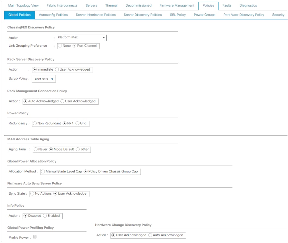
Configure NTP Server
To configure the NTP server for the Cisco UCS environment, follow these steps:
1. Select Admin tab.
2. Select Time Zone Management.
3. Select Time Zone.
4. Under Properties select your time zone.
5. Select Add NTP Server.
6. Enter the IP address of the NTP server.
7. Select OK.
Enable Fabric Interconnect A Ports for Server
To enable server ports, follow these steps:
1. Select the Equipment tab.
2. Select Equipment > Fabric Interconnects > Fabric Interconnect A (primary) > Fixed Module.
3. Click Ethernet Ports section.
4. Select Ports 1-16, right-click and then select Configure as Server Port.
5. Click Yes and then click OK.
6. Repeat the same steps for Fabric Interconnect B.
Enable Fabric Interconnect A Ports for Uplinks
To enable uplink ports, follow these steps:
1. Select the Equipment tab.
2. Select Equipment > Fabric Interconnects > Fabric Interconnect A (primary) > Fixed Module.
3. Click Ethernet Ports section.
4. Select Ports 49-52, right-click and then select Configure as Uplink Port.
5. Click Yes and then click OK.
6. Repeat the same steps for Fabric Interconnect B.
Create Port Channel for Fabric Interconnect A/B
To create Port Channels to the connected Nexus 93180YC-EX switches, follow these steps:
1. Select the LAN tab in the left pane of the Cisco UCS Manager GUI.
2. Go to LAN > LAN Cloud > Fabric A > Port Channels and right-click Create Port Channel.
3. Type in ID 10.
4. Type in vPC10 in the Name field.
5. Click Next.
6. Select the available ports on the left 49-52 and assign them with >> to Ports in the Port Channel.
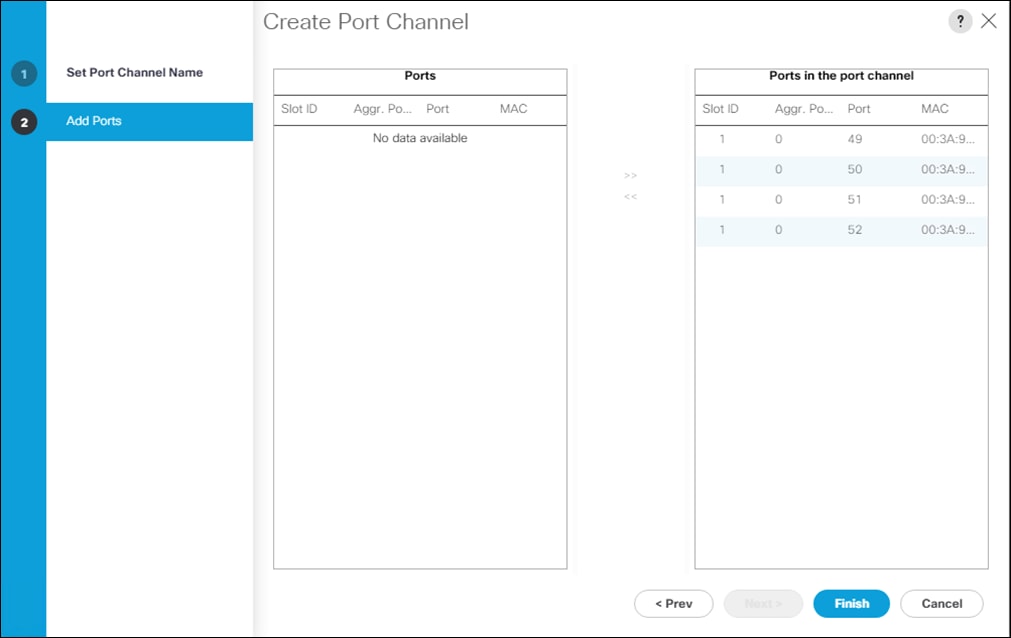
7. Click Finish and then click OK.
8. Repeat the same steps for Fabric B under LAN > LAN Cloud > Fabric B > Port Channels and right-click Create Port Channel.
9. Type in ID 11.
10. Type in vPC11 in the Name field.
11. Click Next.
12. Select the available ports on the left 49-52 and assign them with >> to Ports in the Port Channel.
13. Click Finish and then click OK.
Label Each Server for Identification
To label each chassis for better identification, follow these steps:
1. Select the Equipment tab.
2. Select Chassis > Chassis 1.
3. In the Properties section on the right go to User Label and add Slicestor 1/2 to the field.
4. Repeat the previous steps for Chassis 1 – 3 by using the following labels (Table 10):
| Chassis |
Name |
| Chassis 1 |
Slicestor 1/2 |
| Chassis 2 |
Slicestor 3/4 |
| Chassis 3 |
Slicestor 5/6 |
| Chassis 4 |
Slicestor 7/8 |
| Chassis 5 |
Slicestor 9/10 |
| Chassis 6 |
Slicestor 11/12 |
5. Select Chassis 1 -> Servers -> Server 1.
6. In the Properties section on the right go to User Label and add Slicestor 1 to the field.
7. Repeat steps 5-6 for Server 2 and each chassis by using the following labels (Table 11):
| Chassis |
Server |
Name |
| Chassis 1 |
Server 1 |
Slicestor 1 |
| Chassis 1 |
Server 2 |
Slicestor 2 |
| Chassis 2 |
Server 3 |
Slicestor 3 |
| Chassis 2 |
Server 4 |
Slicestor 4 |
| Chassis 3 |
Server 5 |
Slicestor 5 |
| Chassis 3 |
Server 6 |
Slicestor 6 |
| Chassis 4 |
Server 7 |
Slicestor 7 |
| Chassis 4 |
Server 8 |
Slicestor 8 |
| Chassis 5 |
Server 9 |
Slicestor 9 |
| Chassis 5 |
Server 10 |
Slicestor 10 |
| Chassis 6 |
Server 11 |
Slicestor 11 |
| Chassis 6 |
Server 12 |
Slicestor 12 |
8. Select Rack-Mounts -> Servers -> Server 1.
9. In the Properties section go to User Label and add HyperFlex Node 1 to the field.
10. Repeat steps 8-9 for each Rack-Mount server by using the following labels (Table 12):
| Chassis |
Name |
| Server 1 |
HyperFlex Node 1 |
| Server 2 |
HyperFlex Node 2 |
| Server 3 |
HyperFlex Node 3 |
| Server 4 |
HyperFlex Node 4 |
Create KVM IP Pool
To create a KVM IP Pool, follow these steps:
1. Select the LAN tab.
2. Go to LAN > Pools > root > IP Pools and right-click Create Block of IPv4 Addresses.
3. Type in IBMCOS-IP as Name.
4. (Optional) Enter a Description of the MAC Pool.
5. Set Assignment Order as Sequential.
6. Click Next and then click Add.
7. Enter an IP Address in the From field.
8. Enter Size 20.
9. Enter your Subnet Mask.
10. Fill in your Default Gateway.
11. Enter your Primary DNS and Secondary DNS if needed.
12. Click OK.
13. Click Next, click Finish and then click OK.
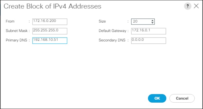
Create MAC Pool
To create a MAC Pool, follow these steps:
1. Select the LAN tab.
2. Go to LAN > Pools > root > Mac Pools and right-click Create MAC Pool.
3. Type in IBMCOS-MAC as Name.
4. (Optional) Enter a Description of the MAC Pool.
5. Set Assignment Order as Sequential.
6. Click Next.
7. Click Add.
8. Specify a starting MAC address.
9. Specify a size of the MAC address pool, which is sufficient to support the available server resources, for example, 100.
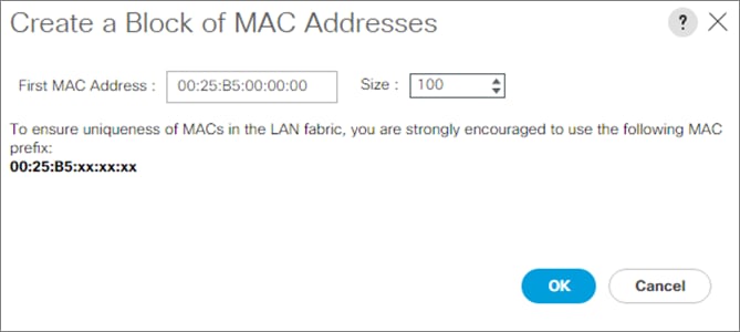
10. Click OK.
11. Click Finish and then click OK.
Create UUID Pool
To create a UUID Pool, follow these steps:
1. Select the Servers tab.
2. Go to Servers > Pools > root > UUID Suffix Pools and right-click Create UUID Suffix Pool.
3. Type in IBMCOS-UUID as Name.
4. (Optional) Enter a Description of the UUID Pool.
5. Set Assignment Order to Sequential and click Next.
6. Click Add.
7. Specify a starting UUID Suffix.
8. Specify a size of the UUID suffix pool, which is sufficient to support the available server resources, for example, 20.
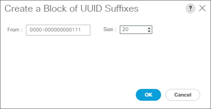
9. Click OK.
10. Click Finish and then click OK.
Create Network Control Policy
To enable Network Control Policies, follow these steps:
1. From the Cisco UCS Manager GUI, Click the LAN tab.
2. Go to LAN > Policies > root > Network Control Policies and right-click Create Network-Control Policy.
3. Type in IBMCOS-CDP in the Name field.
4. (Optional) Enter a description in the Description field.
5. Click Enabled under CDP.
6. Click Only Native Vlan under MAC Register Mode.
7. Click OK.
8. Click OK.
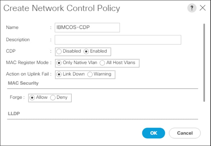
VLAN Setup
In the next section, you’ll create different VLANs for the different vNICs according to Table 5:
| VLAN Name |
VLAN ID |
| Management |
100 |
| Data/Storage |
101 |
| Client |
102 |
To enable Network Control Policies, follow these steps:
1. From the Cisco UCS Manager GUI, click the LAN tab.
2. Go to LAN > LAN Cloud > VLANs right-click Create VLANs.
3. Type in Management for VLAN Name/Prefix and 100 for VLAN IDs.
4. Repeat steps 1-3 for VLAN 101 and 102.
5. Click OK.
6. Click OK and then click OK again.
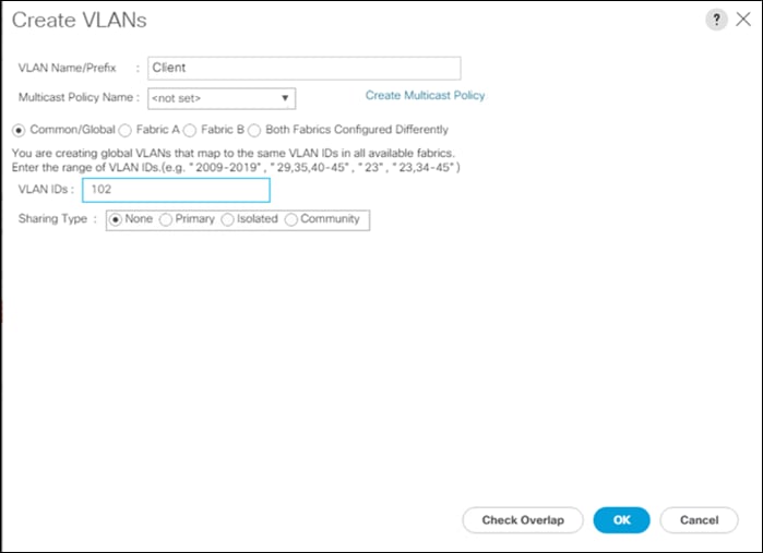
vNIC Template Setup
The next step is to create the appropriate vNIC templates. For IBM COS you need to create three vNIC. These vNICs will handle Management, Storage, and Client traffic.
| vNIC Name |
VLAN ID |
VLAN Name |
Fabric Interconnect |
Failover |
MTU Size |
Adapter Policy |
| Management |
100 |
Management |
A |
X |
1500 |
VMware |
| Data-A |
101 |
Data |
A |
X |
9000 |
IBMCOS |
| Data-B |
101 |
Data |
B |
X |
9000 |
IBMCOS |
| Client-A |
102 |
Client |
A |
X |
9000 |
IBMCOS |
| Client-B |
102 |
Client |
B |
X |
9000 |
IBMCOS |
To create the appropriate vNIC, follow these steps:
1. From the Cisco UCS Manager GUI, click the LAN tab.
2. Go to LAN > Policies > root > vNIC Templates and right-click Create vNIC Template.
3. Type in Management in the Name field.
4. (Optional) Enter a description in the Description field.
5. Click Fabric A as Fabric ID and enable failover.
6. Click Updating Template as Template Type.
7. Select Management as VLAN and click Native VLAN.
8. Type in 1500 for MTU Size.
9. Select IBMCOS-MAC as MAC Pool.
10. Select IBMCOS-CDP as Network Control Policy.
11. Click OK and then click OK again.
12. Repeat steps 1-11 for the other vNICs Data-A, Data-B, Client-A and Client-B according to Table 14.
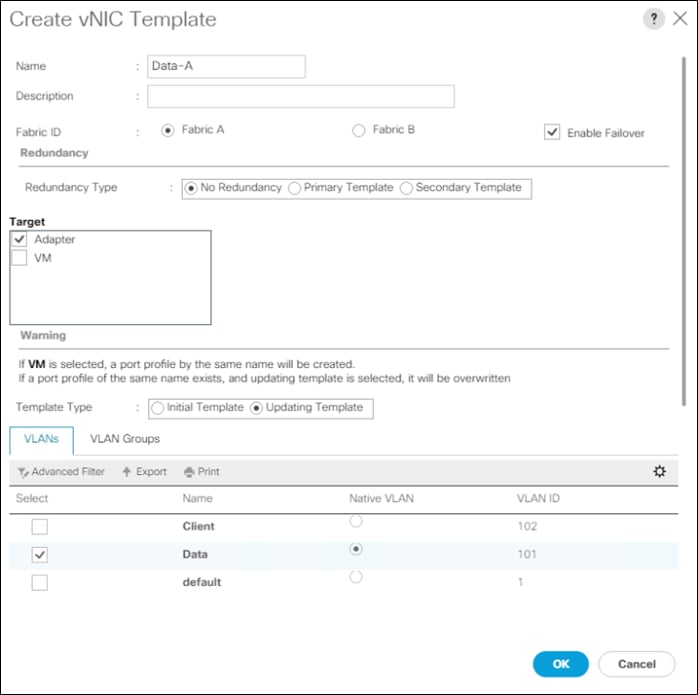
Adapter Policy Setup
To create a specific adapter policy for IBM COS, follow these steps:
1. From the Cisco UCS Manager GUI, click the Server tab.
2. Go to Servers > Policies > root > Adapter Policies and right-click Create Ethernet Adapter Policy.
3. Type in IBMCOS in the Name field.
4. (Optional) Enter a description in the Description field.
5. Under Resources type in the following values:
a. Transmit Queues: 8
b. Ring Size: 4096
c. Receive Queues: 8
d. Ring Size: 4096
e. Completion Queues: 16
f. Interrupts: 32
6. Under Options enable Receive Side Scaling (RSS) and Accelerated Receive Flow Steering.
7. Click OK and then click OK again.
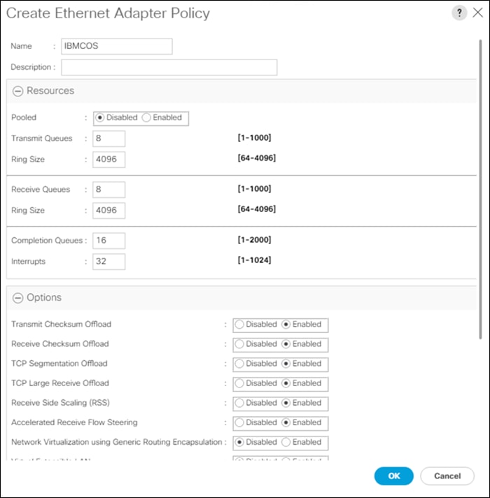
Create LAN Connectivity Policy
To simplify the setup of your network within the Service Profiles create a LAN Connectivity Policy by following these steps:
1. From the Cisco UCS Manager GUI, click the LAN tab.
2. Go to LAN > Policies > root > LAN Connectivity Policies and right-click Create LAN Connectivity Policy.
3. Type in IBMCOS-LAN in the Name field.
4. (Optional) Enter a description in the Description field.
5. Click Add.
6. Click Use vNIC Template and type Management under Name.
7. Select vNIC Template Management and Adapter Policy VMware according to Table 4.
8. Click OK and repeat the same steps for vNIC Data-A, Data-B, Client-A and Client-B according to Table 14.
9. Click OK, then click OK, and click OK again.
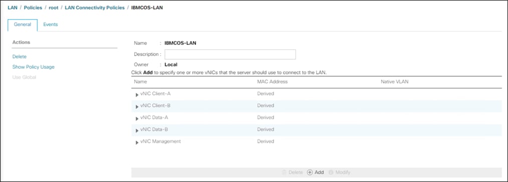
Create vNIC Placement Policy
To make sure that you get the maximum network performance we create a vNIC Placement Policy to distribute the vNICs in a linear order over the vCONs (see https://www.cisco.com/c/en/us/td/docs/unified_computing/ucs/ucs-manager/GUI-User-Guides/Server-Mgmt/4-0/b_Cisco_UCS_Manager_Server_Mgmt_Guide_4_0/b_Cisco_UCS_Manager_Server_Mgmt_Guide_4_0_chapter_01011.html#concept_y13_5tk_ndb). It might be not that important if there is only one adapter but could be interesting when two adapters in a single-node Cisco UCS S3260 M5 are in use.
To create the vNIC Placement Policy, follow these steps:
1. Select the Server tab in the left pane of the Cisco UCS Manager GUI.
2. Go to Servers > Policies > root > vNIC/vHBA Placement Policies and right-click Create Placement Policy.
3. Type in IBMCOS-Placement in the Name field.
4. Select Linear Ordered under Virtual Slot Mapping Scheme.
5. Double-Click on each Transport line of the Virtual Slot and retain ethernet.
6. Click OK and then click OK again.
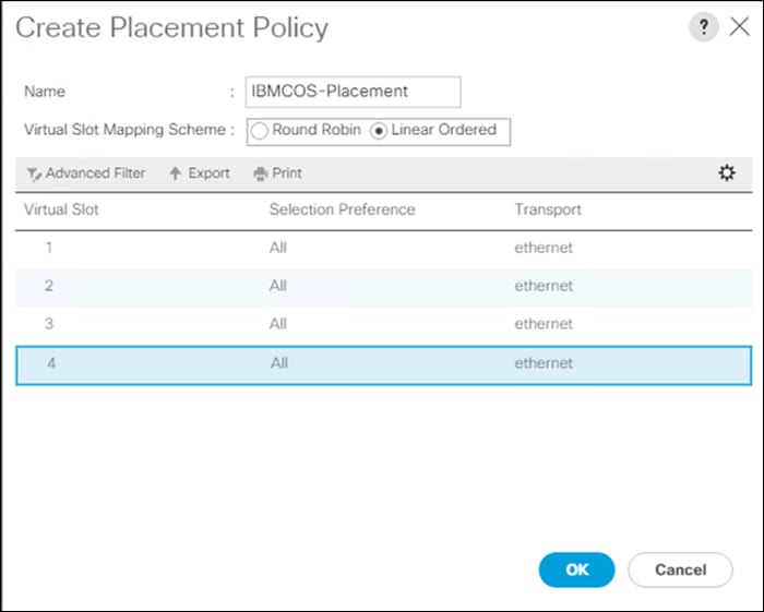
Boot Policy Setup
To create a Boot Policy, follow these steps:
1. Select the Servers tab in the left pane.
2. Go to Servers > Policies > root > Boot Policies and right-click Create Boot Policy.
3. Type in IBMCOS-Boot in the Name field.
4. (Optional) Enter a description in the Description field.
5. Click Local Devices > Add Local LUN and leave Any as default.
6. Click OK.
7. Click CIMC Mounted vMedia > Add CIMC Mounted CD/DVD
8. Click OK.
9. Click OK.
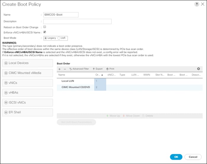
Create Maintenance Policy Setup
To setup a Maintenance Policy, follow these steps:
1. Select the Servers tab in the left pane.
2. Go to Servers > Policies > root > Maintenance Policies and right-click Create Maintenance Policy.
3. Type in IBMCOS-Maint in the Name field.
4. (Optional) Enter a description in the Description field.
5. Click User Ack under Reboot Policy.
6. Click OK and then click OK again.
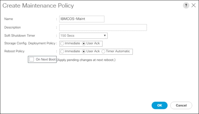
Create Power Control Policy Setup
To create a Power Control Policy, follow these steps:
1. Select the Servers tab in the left pane.
2. Go to Servers > Policies > root > Power Control Policies and right-click Create Power Control Policy.
3. Type in IBMCOS-Power in the Name field.
4. (Optional) Enter a description in the Description field.
5. Click No Cap.
6. Click OK and then click OK again.
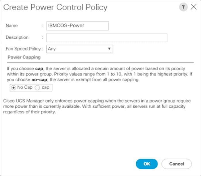
Create Host Firmware Package
To create a Host Firmware Policy, follow these steps:
1. Select the Servers tab in the left pane.
2. Go to Servers > Policies > root > Host Firmware Packages and right-click Create Host Firmware Package.
3. Type in IBMCOS-FW in the Name field.
4. (Optional) Enter a description in the Description field.
5. Under Rack Package select 4.1(1c)C.
6. Deselect Local Disk.
7. Click OK and then click OK again.
Create vMedia Policy in Cisco UCS Manager
To simplify the installation of the hardware agnostic IBM image, create the vMedia policy for the IBM Service Profile and follow these steps:
1. Select the Servers tab in the left pane.
2. Go to Servers > Policies > root > vMedia Policies and right-click Create vMedia Policy.
3. Type in IBMCOS-vMedia in the Name field.
4. (Optional) Enter a description in the Description field.
5. Click Add.
6. Type in IBMCOS-ISO in the Name field.
7. (Optional) Enter a description in the Description field.
8. Click CDD for Device Type.
9. Click HTTP for Protocol.
10. Type in the Hostname/IP Address.
11. Type in clevos-3.14.11.39-allinone-usbiso.iso for Remote File.
12. Type in images for Remote Path.
13. Click OK, click OK again, and then click OK.
Create Storage Profiles
Next, you’ll create the Disk Group Policy and Storage Profile for the boot devices for the rear end SATA SSDs.
Create Disk Group Policy for Boot Devices
To create the Disk Group Policy from the rear end SATA SSDs, follow these steps:
1. Select Storage in the left pane of the Cisco UCS Manager GUI.
2. Go to Storage > Storage Policies > root > Disk Group Policies and right-click Create Disk Group Policy.
3. Type in IBMCOS-Boot in the Name field.
4. (Optional) Enter a description in the Description field.
5. Select RAID 1 Mirrored for RAID Level.
6. Click Disk Group Configuration (Manual).
7. Click Add.
8. Type in 201 as slot number.
9. Repeat the step for slot number 202.
10. Under Virtual Drive Configuration select Write Back Good Bbu under Write Cache Policy.
11. Click OK and then click OK again.
Create Storage Profile
To create the Storage Profile, follow these steps:
1. Select Storage in the left pane of the Cisco UCS Manager GUI.
2. Go to Storage > Storage Profiles and right-click Create Storage Profile.
3. Type in IBMCOS-Disk in the Name field.
4. (Optional) Enter a description in the Description field.
5. Click Add under Local LUN.
6. Type in Boot in the Name field.
7. Click Expand To Available.
8. Select IBMCOS-Boot under Select Disk Group Configuration.
9. Click OK, then click OK, and click OK again.
Create Chassis Profiles
Before you start building the Service Profiles you need to create Chassis Policies and Profiles to configure the Cisco UCS S3260 Chassis.
Create Chassis Firmware Package
To create a Chassis Firmware Package, follow these steps:
1. Select the Chassis tab in the left pane of the Cisco UCS Manager GUI.
2. Go to Chassis > Policies > root > Chassis Firmware Package and right-click Create Chassis Firmware Package.
3. Type in IBMCOS-CHFW in the Name field.
4. (Optional) Enter a description in the Description field.
5. Select 4.1(1c)C from the drop-down list of Chassis Package.
6. Deselect Local Disk from the Excluded Components.
7. Select OK and then click OK again.
Create Chassis Maintenance Policy
To create a Chassis Maintenance Policy, follow these steps:
1. Select the Chassis tab in the left pane of the Cisco UCS Manager GUI.
2. Go to Chassis > Policies > root > Chassis Maintenance Policies and right-click Create Chassis Maintenance Policy.
3. Type in IBMCOS-Maint in the Name field.
4. (Optional) Enter a description in the Description field.
5. Select OK and then click OK again.
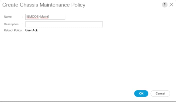
Create Compute Connection Policy
To create a Compute Connection Policy, follow these steps:
1. Select the Chassis tab in the left pane of the Cisco UCS Manager GUI.
2. Go to Chassis > Policies > root > Compute Connection Policies and right-click Create Compute Connection Policy.
3. Type in IBMCOS-Conn in the Name field.
4. (Optional) Enter a description in the Description field.
5. Select Single Server Single SIOC.
6. Select OK and then click OK again.
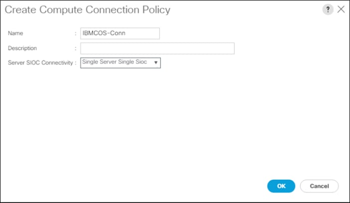
Create Disk Zoning Policy
To create a Disk Zoning Policy, follow these steps:
1. Select the Chassis tab in the left pane of the Cisco UCS Manager GUI.
2. Go to Chassis > Policies > root > Disk Zoning Policies and right-click Create Disk Zoning Policy.
3. Type in IBMCOS-Zone in the Name field.
4. (Optional) Enter a description in the Description field.
5. Click Add.
6. Under Ownership click Dedicated.
7. Under Server select Server 1 and under Controller select Controller 1.
8. Add Slot 1-14 under Slot Range.
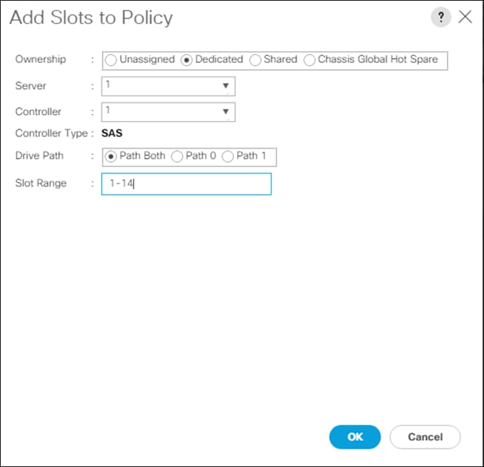
9. Repeat steps 5-8 according to the following table:
Table 15 Disk Zoning S3260
| Server |
Controller |
Slot Range |
| 1 |
1 |
1-14 |
| 1 |
2 |
15-28 |
| 2 |
1 |
29-42 |
| 2 |
2 |
43-56 |
10. Select OK and then click OK again.
Create Sas Expander Configuration Policy
To create a Sas Expander Configuration Policy, follow these steps:
1. Select the Chassis tab in the left pane of the Cisco UCS Manager GUI.
2. Go to Chassis > Policies > root > Sas Expander Configuration Policies and right-click Create Sas Expander Configuration Policy.
3. Type in IBMCOS-SAS in the Name field.
4. (Optional) Enter a description in the Description field.
5. Select OK and then click OK again.
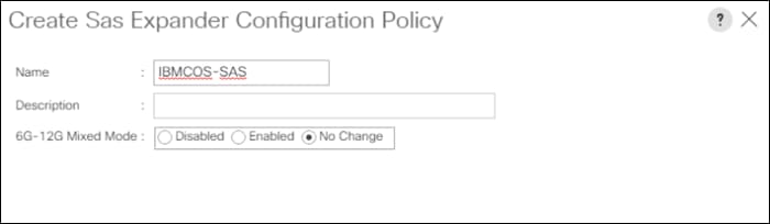
Create Chassis Profile Template
To create a Chassis Profile Template, follow these steps:
1. Select the Chassis tab in the left pane of the Cisco UCS Manager GUI.
2. Go to Chassis > Chassis Profile Templates and right-click Create Chassis Profile Template.
3. Type in IBMCOS-Chassis in the Name field.
4. Under Type, select Updating Template.
5. Optional) Enter a description in the Description field.
6. Click Next.
7. Under the radio button Chassis Maintenance Policy, select your previously created Chassis Maintenance Policy.
8. Click Next.
9. Under the radio button Chassis Firmware Package, Compute Connection Policy, and Sas Expander Configuration Policy, select your previously created Policies.
10. Click Next.
11. Under the radio button Disk Zoning Policy, select your previously created Disk Zoning Policy.
12. Click Finish and then click OK.
Create Chassis Profile from Template
To create the Chassis Profiles from the previous created Chassis Profile Template, follow these steps:
1. Select the Chassis tab in the left pane of the Cisco UCS Manager GUI.
2. Go to Chassis > Chassis Profile Templates and select “IBMCOS-Chassis” you created previously.
3. Then right click to select Create Chassis Profiles from Template.
4. Type in S3260-Chassis in the Name field.
5. Leave the Name Suffix Starting Number untouched.
6. Enter 6 for the Number of Instances for all connected Cisco UCS S3260 Storage Server.
7. Click OK and then click OK again.
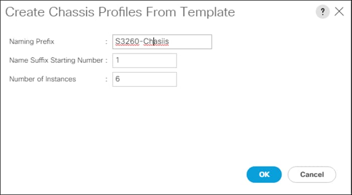
Associate Chassis Profiles
To associate all previous created Chassis Profile, follow these steps:
1. Select the Chassis tab in the left pane of the Cisco UCS Manager GUI.
2. Go to Chassis > Chassis Profiles and select S3260-Chassis1.
3. Right-click Change Chassis Profile Association.
4. Under Chassis Assignment, choose Select existing Chassis from the drop-down list.
5. Under Available Chassis, select ID 1.
6. Click OK and then click OK again.
7. Repeat steps 1-6 for the other two Chassis Profiles by selecting the IDs 2 – 6.
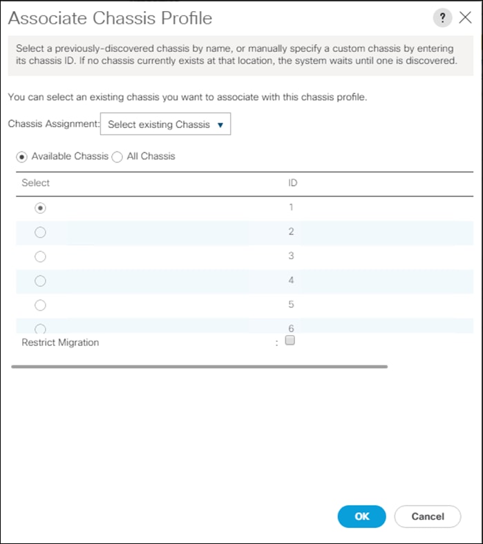
8. A pop-up will appear on the top right side. Click Chassis Profiles and Acknowledge All Chassis profiles.
9. Click Apply.
10. Click OK.
Create Service Profile Template
To create service profile templates, follow the steps in the following sections.
Create Service Profile Template
1. Select Servers in the left pane of the Cisco UCS Manager GUI.
2. Go to Servers > Service Profile Templates and right-click Create Service Profile Template.
Identify Service Profile Template
1. Type in IBMCOS in the Name field.
2. Click Updating Template in Type.
3. In the UUID Assignment section, select the IBMCOS-UUID Pool.
4. (Optional) Enter a description in the Description field.
5. Click Next.
Storage Provisioning
1. Go to the Storage Profile Policy tab and select the Storage Profile IBMCOS-Disk.
2. Click Next.
Networking
1. Select the Use Connectivity Policy radio button for the option How would you like to configure LAN connectivity?
2. Select the Connectivity Policy IBMCOS-LAN.
3. Click Next to continue with SAN Connectivity.
4. Select No vHBA for How would you like to configure SAN Connectivity?
5. Click Next to continue with Zoning.
6. Click Next to continue with vNIC/vHBA Placement.
7. Select IBMCOS-Placement Policy under Select Placement
8. Select all five vNIC interfaces on the left and select vCon 1 on the right.
9. Select the >> button to move the vNICs over to vCon 1.
10. Change the order of the vNICs under vCon 1 with Management first, Data-A second, Data-B third, Client-B fourth and Client-A fifth.
![]() When creating active-backup bonding under ClevOS, ClevOS takes the first client NIC and the appropriate MAC address to build the bond. The above configuration makes sure that the client traffic goes through FI-B.
When creating active-backup bonding under ClevOS, ClevOS takes the first client NIC and the appropriate MAC address to build the bond. The above configuration makes sure that the client traffic goes through FI-B.
11. Click Next to continue with vMedia Policy.
vMedia Policy
1. Select IBMCOS-vMedia from the vMedia Policy Menu.
2. Click Next.
Server Boot Order
1. Select IBMCOS-Boot from the Boot Policy Menu.
2. Click Next.
Server Maintenance
1. Select the Maintenance Policy IBMCOS-Maint under Maintenance Policy.
2. Click Next.
Firmware Management
1. Select the Firmware Policy IBMCOS-FW under Firmware Management
2. Click Next,
Operational Policies
1. Under Management IP Address click the Outband tab and select IBMCOS-IP under Management IP Address Policy.
2. Under Power Control Policy Configuration select IBMCOS-Power.
3. Click Finish.
Create Service Profiles from Template
Create the appropriate Service Profiles from the previous Service Profile Template. To create all 12 profiles for the IBM Server, follow these steps:
1. Select Servers from the left pane of the Cisco UCS Manager GUI.
2. Go to Servers > Service Profiles and right-click Create Service Profiles from Template.
3. Type in Slicestor in the Name Prefix field.
4. Type 1 for Name Suffix Starting Number.
5. Type 12 for Number of Instances.
6. Choose IBMCOS under Service Profile Template.
7. Click OK.
Associate Service Profiles
To associate the service profiles, follow these steps:
1. Right-click the service profile Slicestor1 and choose Change Service Profile Association.
2. Server Assignment should be Select Existing Server.
3. Select Chassis ID 1, Slot 1.
4. Click OK and Yes and OK.
5. Repeat the steps for the all Service Profiles counting up the Chassis ID and Slot ID corresponding with the service profile.
The formal setup of the Cisco UCS Manager environment for IBM Cloud Object Storage and both Cisco Nexus 93180YC-EX switches is now finished, and the installation of Cisco Intersight will continue. The complete steps of installing and configuring IBM Cloud Object Storage on Cisco UCS S3260 M5 was published in a recent Cisco Validated Design, which can be found here: https://www.cisco.com/c/en/us/td/docs/unified_computing/ucs/UCS_CVDs/versastack_ibmcos_s3260m5.html#_Toc40804525
Installation of Cisco Intersight Virtual Appliance
Cisco Intersight provides infrastructure management for Cisco Unified Compute System (Cisco UCS) and Cisco HyperFlex platforms. This platform offers an intelligent level of management that enables IT organizations to analyze, simplify, and automate their environments in more advanced ways than previous generations of tools.
Cisco Intersight Virtual Appliance delivers the management features of Intersight for Cisco UCS and HyperFlex in an easy to deploy VMware OVA that allows you to control what system details leave your premises. The Virtual Appliance form factor enables additional data locality, security, or compliance needs that are not completely met by intersight.com. Cisco Intersight Virtual Appliance requires a connection back to Cisco and Intersight services for updates and access required services for full functionality of intersight.com. Cisco Intersight Virtual Appliance is not intended for an environment where you operate data centers with no external connectivity.
You can deploy Cisco Intersight Virtual Appliance as a virtual machine in your existing environment quickly in a few easy steps, which are detailed in the following sections. This guide provides an overview of how to install and set up Cisco Intersight Virtual Appliance in your environment.
Licensing Requirements
Cisco Intersight Virtual Appliance uses a subscription-based license that is required to use the features of the appliance. Intersight Essentials is a subscription license delivered via Cisco Smart Licensing. Enabled platforms are those Cisco UCS and Cisco HyperFlex systems with a Cisco Intersight device connector, including eligible Cisco UCS Manager, Cisco IMC, Cisco HyperFlex software.
You must register the license as part of the initial setup of Cisco Intersight Virtual Appliance. After you complete the installation of the appliance OVA, launch the UI and set up a password, connect the appliance to Intersight, and register the license.
You can obtain an Intersight evaluation license for Cisco Intersight Virtual Appliance from your Cisco sales representative, channel partner, or reseller. If you already have a Cisco Smart Account, the evaluation license will be added to your Cisco Smart Account. You can then generate a token for the virtual account in the Smart account and proceed with registering Cisco Intersight Virtual Appliance. In our validated design we obtained an evaluation license for 90 days.
VM Configuration Requirements
The Cisco Intersight Virtual Appliance OVA can be deployed on VMware ESXi 6.0 and higher. The following sections describe the various system requirements to install and deploy Cisco Intersight Virtual Appliance:
You can deploy Intersight Virtual Appliance in the Small or Medium options. For more information on the resource requirements and supported maximum configuration limits for Intersight Virtual Appliance Sizing Options, see Intersight Virtual Sizing Options.
Table 16 Resource Requirements for the Intersight Virtual Appliance
| Resource Requirements |
System Requirements |
|
| Small |
Medium |
|
| vCPU |
16 |
24 |
| RAM (GiB) |
32 |
64 |
| Storage (Disk)(GiB) |
500 Cisco recommends that you use thick provisioning |
500 Cisco recommends that you use thick provisioning |
| Number of servers |
2000 |
5000 |
| Supported Hypervisors |
VMware ESXi 6.0 and higher VMware vSphere Web Client 6.5 and higher |
|
IP Address and Hostname Requirements
Setting up Intersight Appliance requires an IP address and 2 hostnames for that IP address. The hostnames must be in the following formats:
· myhost.mydomain.com—A hostname in this format is used to access the GUI. This must be defined as an A record and PTR record in DNS. The PTR record is required for reverse lookup of the IP address. For details about Regular Expression for a valid hostname, see RFC 1123. If an IP address resolves to multiple hostnames, the first resolved hostname is used.
· dc-myhost.mydomain.com—The dc- must be prepended to your hostname. This hostname must be defined as the CNAME of myhost.mydomain.com. Hostnames in this format are used internally by the appliance to manage device connections.
![]() Ensure that the appropriate entries of type A, CNAME, and PTR records exist in the DNS, as described above.
Ensure that the appropriate entries of type A, CNAME, and PTR records exist in the DNS, as described above.
Port Requirements
The following table lists the ports required to be open for Intersight Appliance communication.
Table 17 Port requirements for Cisco Intersight
| Port |
Protocol |
Description |
| 443 |
TCP/UDP |
This port is required for communication between: · Intersight Virtual Appliance and the users' web browser. · Intersight Virtual Appliance to and from the endpoint devices. |
| 80 |
TCP |
This port is optional for normal operation but is required for initial monitoring of the appliance setup and when using the one-time device connector upgrade. For more information, see Device Connector Upgrade. This port is used for communication between: · Intersight Virtual Appliance and the user's web browser for initial monitoring of the appliance setup and when using the one-time device connector upgrade. · Appliance and the endpoint device for upgrade of the device connector. Port 80 is required when the device connector version is lower than the minimum supported version. For more information, see Device Connector Requirements. Port 80 is not used if the device connector is at the minimum supported version. |
Connectivity Requirements
Ensure that Cisco Intersight Virtual Appliance has access to the following sites directly or through a proxy. For more information about setting up a proxy, see Cloud Connection. All the following URLs are accessed through HTTPS:
· Access to Cisco services (*.cisco.com).
- tools.cisco.com:443—for access to Cisco Smart Licensing Manager
- api.cisco.com:443— for access to Cisco Software download site
· Access to Intersight Cloud services.
Intersight Virtual Appliance connects to Intersight by resolving one of the following URLs:
· svc.intersight.com—(Preferred)
· svc.ucs-connect.com—(Will be deprecated in the future)
· IP address for any given URL could change. In case you need to specify firewall configurations for URLs with fixed IPs, use one of the following:
svc-static1.intersight.com—(Preferred)
· svc-static1.ucs-connect.com—(Will be deprecated in the future)
Both these URLs resolve to the following IP addresses:
· 3.208.204.228
· 54.165.240.89
· 3.92.151.78
Install Cisco Intersight Virtual Appliance Using VMware vSphere Web Client
Cisco Intersight Virtual Appliance is distributed as a deployable virtual machine contained in an Open Virtual Appliance (OVA) file format. You can install the appliance on an ESXi server. Cisco Intersight Virtual Appliance supports VMware High Availability (VMHA) to ensure non-disruptive operation of the virtual appliance.
Ensure that you have downloaded the Cisco Intersight Virtual Appliance package from the URL provided by your Cisco representative or a location accessible from your setup, such as a local hard drive, a network share, or a CD/DVD drive.
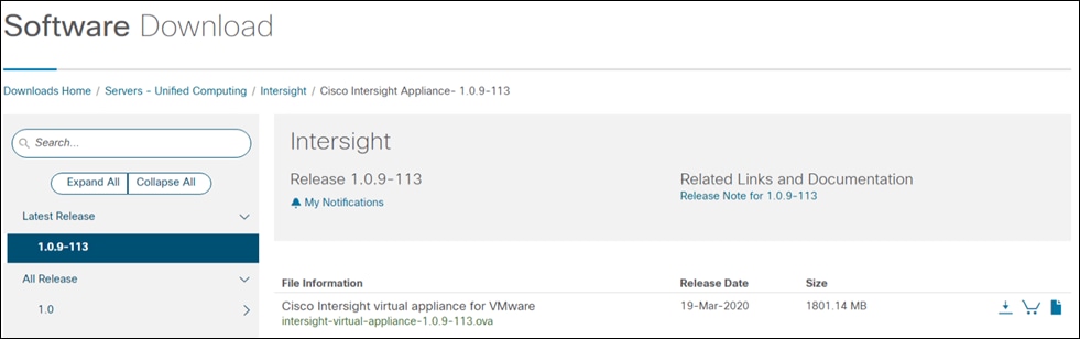
To install and deploy the appliance using a VMware vSphere Web Client, follow these steps:
1. Log into VMware vSphere Web Client with administrator credentials.
2. Right-click on the host and select Deploy OVF Template.
3. On the Deploy OVF Template wizard Select template page, specify the source location, and click Next. You can specify a URL or browse to location accessible from your local hard drive, a network share, or a DVD/CD drive.
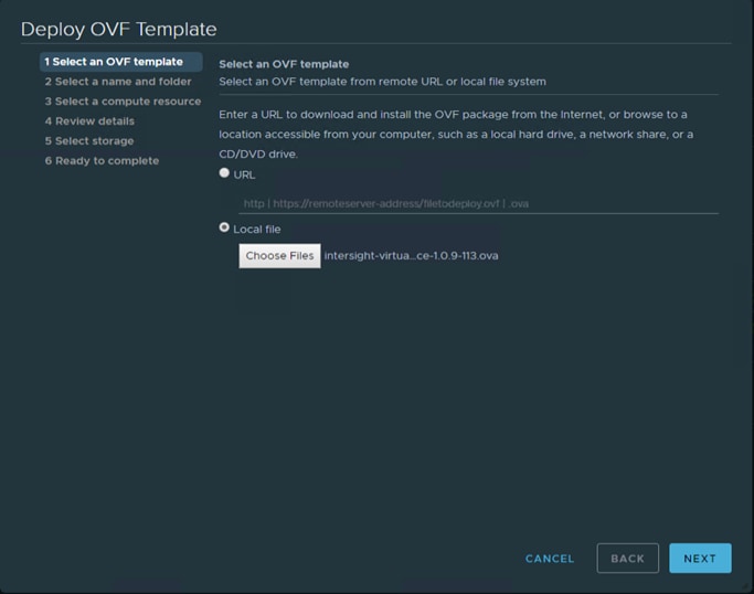
4. On the OVF Template Details page, verify the OVF template details and click Next. No input is necessary.
5. On the Select a name and location page, add/edit the Name and Location for the Virtual appliance, and click Next.
6. On the Select a resource page, select the specific Host (ESX station), Cluster, Resource Pool, or virtual appliance you want to deploy and click Next.
7. Each VM must be assigned to a specific host on clusters that are configured with vSphere HA or Manual mode vSphere DRS.
8. On the Review details page, verify the OVA template details and click Next.
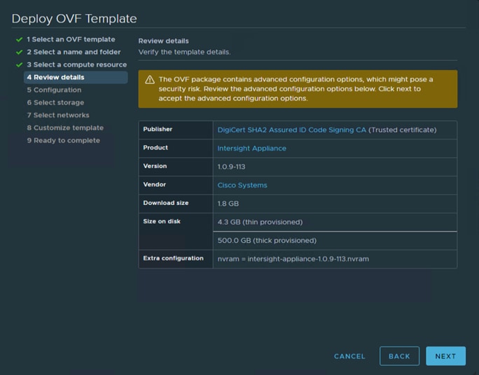
9. On the Configuration page, select a deployment configuration and click Next. You can select Small or Medium deployment configuration based on your requirement for Intersight Virtual Appliance. A brief description of the selected size displays. You can select Tiny (8 vCPU, 16 Gi RAM) deployment configuration for Intersight Assist only.
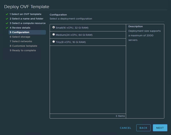
10. On the Select storage page, select a destination storage (hard drives) for the VM files in the selected host (ESX station) and click Next. Select the Disk Format for the virtual machine virtual disks. Select Thin Provision to optimize disk usage.
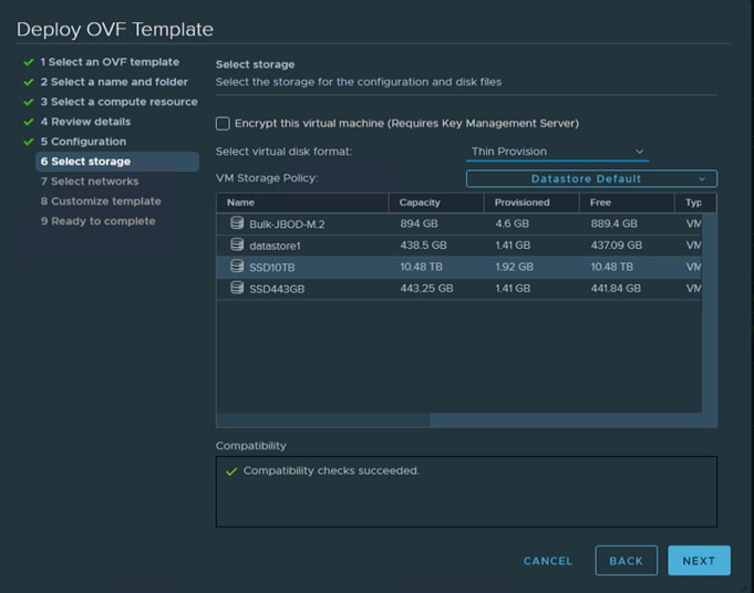
11. On the Select networks page, for each network that is specified in the OVF template, select a source network, and map it to a destination network and click Next.
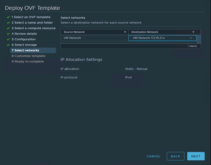
12. On the Customize Template page, customize the deployment properties of the OVF template, and click Next.
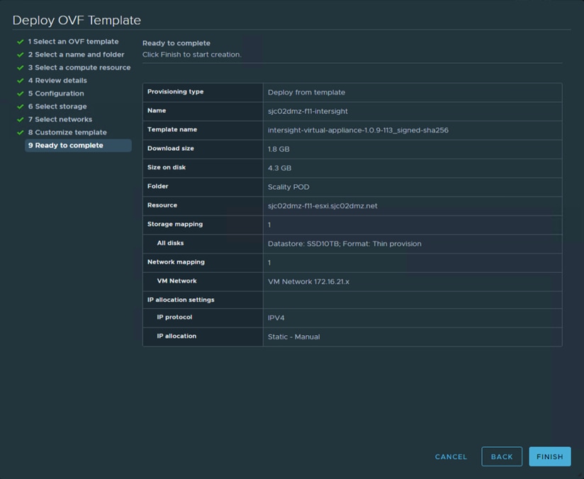
13. After finishing the deployment, power on the virtual machine.
Log into Intersight Virtual Appliance
After installing the Intersight Virtual Appliance OVA, you can then connect to the configured IP address or DNS name. To log into Intersight Virtual Appliance, follow these steps:
1. Select the form of installation “Intersight Connected Virtual Appliance.”
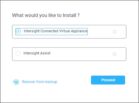
2. After you install the Cisco Intersight Virtual Appliance OVA, go to <<http://your fqdn.com>>. The Initial Setup Wizard appears and allows you to complete the setup for one of the following:
· Intersight Connected Virtual Appliance
· Intersight Assist—For more information, see the Cisco Intersight Assist documentation.
3. Use the following instructions to complete the Intersight Connected Virtual Appliance setup:
a. Select Intersight Connected Virtual Appliance and click Proceed.
The wizard runs through a series of steps to download and install software packages. You can view the progress of the installation. You can expect this process to complete in about an hour’s time. After that the formal setup is finished and you’re redirected to the login page where you have to change the password.
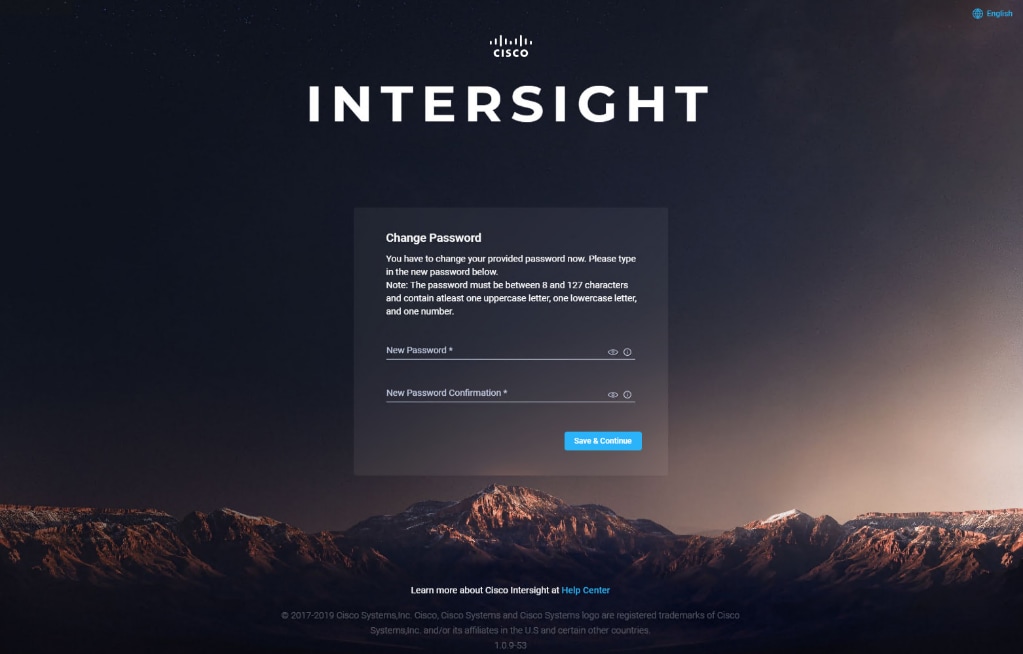
You now see the initial Setup Wizard. The wizard enables you to complete the setup of the Intersight appliance.
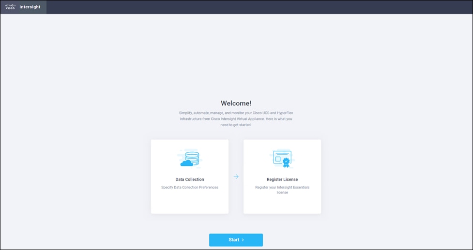
4. Use the following instructions to complete the setup:
· Data Collection—Specify your preference to allow Intersight to send additional system information to Cisco. This option is enabled by default. For more information about what data is collected by Intersight, see Data Collected from Intersight Virtual Appliance.
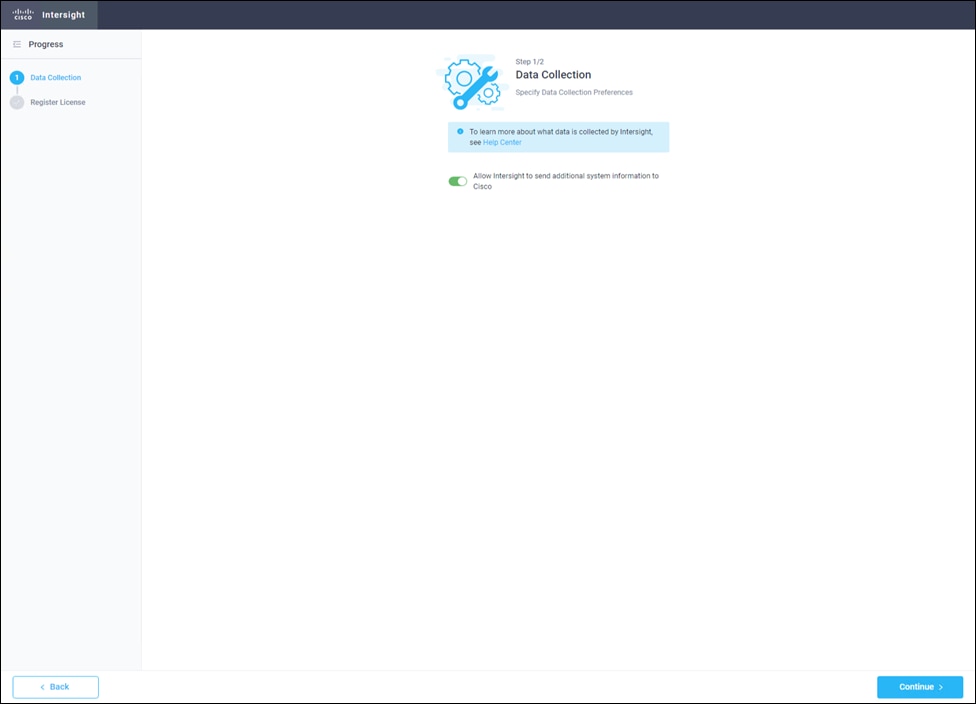
5. Register the Intersight virtual appliance:
· Register License—Click Register License. Obtain a license registration token from Cisco Smart License Manager and apply add the token to activate your license. The license registration process could take a few minutes to complete. For more information about registering your Intersight license, watch Activating Intersight License.
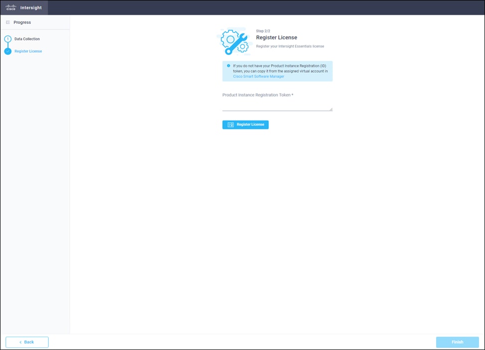
6. Click Finish and the Cisco Intersight Virtual Appliance dashboard displays.
Cisco Intersight Virtual Appliance Settings
Before you start building the solution, you need to configure the virtual appliance for using the right license and for backup.
Set License Tier
You need to make sure that you use the correct license for the solution. For that you need the Essential license. To set the license tier, follow these steps:
1. To change to Essential license, click Settings/Licensing and then click Set Default Tier. Select Essential and click Set.
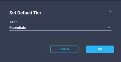
Back up Data
Backing up the Cisco Intersight Virtual Appliance regularly is essential. Without regular backups, there is no automatic way to reconstruct the configuration settings and recreating the profiles and policies. You can perform a regular backup once a day using a scheduled backup or create backup on demand if there is a data loss or corruption event. Cisco Intersight Virtual Appliance enables you to take a full state backup of the data in the appliance and store it in a remote server. If there is a total site failure or other disaster recovery scenarios, the restore capability enables you to do a full state system restore from the backed-up system data.
Schedule Backup enables you to schedule a periodic backup of the data in the Intersight Appliance. The Appliance can store three copies of the backup locally on the appliance. To schedule a backup, follow these steps:
1. Log into Cisco Intersight Virtual Appliance as a user with account administrator role.
2. From the Appliance UI, navigate to Settings icon > Settings > General > Backup, click Schedule Backup.
3. On the Schedule Backup window, toggle ON Use Backup Schedule.
4. If you disable this option, you must enable the Use Backup Schedule option to schedule a backup.
5. Provide the following details to complete creating the Backup Schedule:
a. Backup Schedule:
§ Day of Week—Specify the day in the week when you want to schedule a data backup.
§ Time of Day—Specify the time in the selected day when you want to schedule a data backup. The Time of Day follows the browser time of your session and displays your local time of the day.
b. Backup Destination
§ Protocol—Communication protocol (SCP/ STFP) used in the backup process.
§ Remote Port—Remote TCP port on the backup server.
c. Remote Host—The remote host for saving the backup files.
d. Remote Path—Directory location where the backup files are saved.
e. Filename—Name of the backup file to restore
f. Username—Username for authenticating the backup client to the backup server.
g. Password—Password for authenticating the backup client to the backup server.
h. Password Confirmation—Reenter the password and click Schedule Backup to complete the process.
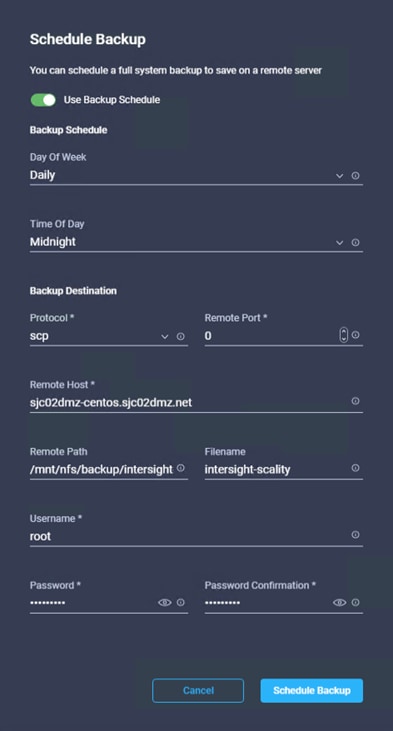
Cisco Intersight provides an installation wizard to install, configure, and deploy Cisco HyperFlex clusters — HyperFlex Edge and FI-attached. The wizard constructs a pre-configuration definition of the cluster called an HyperFlex Cluster Profile. This definition is a logical representation of the HyperFlex nodes in the HyperFlex cluster and includes:
· Security—credentials for HyperFlex cluster such as controller VM password, Hypervisor username, and password.
· Configuration—server requirements, firmware, and so on.
· Connectivity—upstream network, virtual network, and so on.
HyperFlex Cluster Profiles are built on policies which administrator defined sets of rules and operating characteristics such as the node identity, interfaces, and network connectivity. Every active node in the HyperFlex cluster must be associated with an HyperFlex Cluster Profile.
After gathering the node configuration settings to build the HyperFlex Cluster Profile, the installation wizard will validate and deploy the HyperFlex Cluster Profile in the HyperFlex cluster.
The complete flow of the installation process is shown in Figure 70.
Ensure that the system meets the installation and configuration requirements before you begin to install Cisco HyperFlex Fabric Interconnects-attached clusters. Refer to the Preinstallation Checklist for Cisco HX Data Platform for detailed preinstallation requirements.
The complete installation process consists of seven steps:
1. Complete preinstallation checklist.
2. Ensure network is up and running.
3. Log in to Cisco Intersight.
4. Claim Devices.
5. Verify Cisco UCS Firmware versions.
6. Run the Create HyperFlex Cluster Profile Wizard.
7. Run the post installation script through the controller VM.
Claim Devices
To claim the Fabric Interconnect with the HyperFlex Data Platform, follow these steps:
1. Log into the Cisco Virtual Appliance.
2. Select Administration > Devices.
3. In the Devices detail page, click Claim New Device.
4. Under By IP/Name click Device Type and select Cisco UCS Fabric Interconnect (UCSFI).
5. Fill in IP/Hostname, Username, and Password and click Claim.
Verify Firmware Version for Fabric Interconnect
To verify the Firmware version of Cisco UCS Manager and the Fabric Interconnects go to Equipment > Fabric Interconnects and check the Firmware Version.
Configure HyperFlex Fabric Interconnect-Attached Clusters
To configure the HyperFlex fabric interconnect-attached clusters, follow the steps in this section.
General Configuration
To configure a HyperFlex Fabric Interconnect-Attached Cluster in Intersight, follow these steps:
1. Log into Cisco Intersight and click in the left pane on Profiles.
2. Select the tab HyperFlex Cluster Profiles and click on Create HyperFlex Cluster Profile.
3. In the General page select the Organization.
4. Type in a Name of the cluster.
5. Select the HyperFlex Data Platform Version.
6. Select Cisco HyperFlex with Fabric Interconnect for Type.
7. Select Replication Factor 3 for the used configuration.
8. Select Firmware Version 4.0(4h).
![]() Make sure that Firmware version 4.0(4h) for Cisco UCS C-Rack and B-Class servers is uploaded to Cisco UCS Manager.
Make sure that Firmware version 4.0(4h) for Cisco UCS C-Rack and B-Class servers is uploaded to Cisco UCS Manager.
9. Add a Description and click Next.
Cluster Configuration
In the Cluster Configuration page, follow these steps:
Security
1. Leave Hypervisor Admin as root.
2. Select The hypervisor on this node uses the factory default password and fill in the Hypervisor Password and the Controller VM Admin Password.
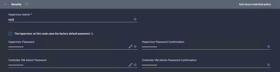
DNS, NTP and Timezone
1. Fill in the Timezone, DNS Suffix, DNS and NTP Servers.
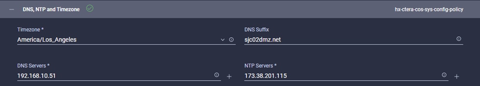
vCenter
1. Type in the vCenter FQDN or IP, vCenter Username, vCenter Password and vCenter Datacenter Name.
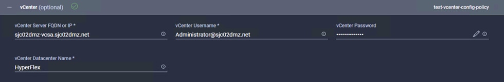
Storage Configuration
1. Select Clean up Disk Partitions.
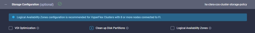
Auto Support
1. If required select Auto Support.
IP & Hostname
1. Fill in the Hostname Prefix.
2. Type in the Management Network Starting and Ending IP, Subnet Mask and Network Gateway.
3. Type in the Controller VM Management Network Starting and Ending IP, Subnet Mask and Network Gateway.
Network Configuration
1. Type in a VM Migration VLAN Name and a VLAN ID.
2. Type in a VM Network VLAN Name and a VLAN ID.
3. Enter a Starting and Ending KVM IP, Subnet Mask and Gateway.
4. Type in a MAC Prefix Starting and Ending Address.
5. Enter a Management Network VLAN Name and ID.
6. Leave Jumbo Frames untouched.
HyperFlex Storage Network
1. Type in the Storage Network VLAN Name and ID.
2. Click Next.
Nodes Assignment
Select all available HyperFlex nodes in the window and click Next.
Nodes Configuration
1. Type in the Cluster Management IP Address and the MAC Prefix Address and validate the details for each node.
2. Click Next.
Summary
Review all the details of your configuration and click Validate. Intersight will download the HyperFlex Installer image and HyperFlex Data Platform packages to validate the configuration.
Results
Review the results for any errors. If there are no errors, then click Validate & Deploy.
When the cluster is deployed you can find the status under HyperFlex Clusters.
Post-Install Configuration
Prior to putting a new HyperFlex cluster into production, a few post-install tasks must be completed. To automate the post installation procedures and verify the HyperFlex cluster configuration, a post install script has been provided on the HyperFlex Controller VMs. To run this script, follow these steps:
1. SSH to the cluster management IP address and login using username and the controller VM password provided during installation. Verify the cluster is online and healthy using “stcli cluster info” or “stcli cluster storage-summary”.
root@SpringpathControllerNDILZYLJ79:~# stcli cluster storage-summary
address: 169.254.161.1
name: HX-CTERA-COS
state: online
uptime: 0 days 8 hours 48 minutes 9 seconds
activeNodes: 4 of 4
compressionSavings: 0.0%
deduplicationSavings: 0.0%
freeCapacity: 31.9T
healingInfo:
inProgress: False
resiliencyInfo:
messages:
Storage cluster is healthy.
state: 1
nodeFailuresTolerable: 1
cachingDeviceFailuresTolerable: 2
persistentDeviceFailuresTolerable: 2
zoneResInfoList: None
spaceStatus: normal
totalCapacity: 32.1T
totalSavings: 0.0%
usedCapacity: 224.1G
zkHealth: online
clusterAccessPolicy: lenient
dataReplicationCompliance: compliant
dataReplicationFactor: 3
2. Run the following command in the shell, and press Enter:
/usr/share/springpath/storfs-misc/hx-scripts/post_install.py
3. Select the first post install workflow type – New/Existing Cluster.
4. Enter the HX Storage Controller VM root password for the HX cluster (use the one entered during the HX Cluster installation).
5. Enter the vCenter server username and password.
6. Enter ESXi host root password (use the one entered during the HX Cluster installation).
7. You must license the vSphere hosts through the script or complete this task in vCenter before continuing.
8. Failure to apply a license will result in an error when enabling HA or DRS in subsequent steps. Enter “n” if you have already registered the license information in vCenter.
9. Enter “y” to enable HA/DRS.
10. Enter “y” to disable the ESXi hosts’ SSH warning.
11. Add the vMotion VMkernel interfaces to each node by entering “y”. Input the netmask, the vMotion VLAN ID, and the vMotion IP addresses for each of the hosts as prompted.
12. You may add VM network portgroups for guest VM traffic. Enter “n” to skip this step and create the portgroups manually in vCenter. Or if desired, VM network portgroups can be created and added to the vm-network vSwitch. This step will add identical network configuration to all nodes in the cluster.
13. Enter “y” to run the health check on the cluster.
14. A summary of the cluster will be displayed upon completion of the script. Make sure the cluster is healthy.
root@SpringpathControllerNDILZYLJ79:~# /usr/share/springpath/storfs-misc/hx-scripts/post_install.py
Select post_install workflow-
1. New/Existing Cluster
2. Expanded Cluster (for non-edge clusters)
3. Generate Certificate
Note: Workflow No.3 is mandatory to have unique SSL certificate in the cluster.
By Generating this certificate, it will replace your current certificate.
If you're performing cluster expansion, then this option is not required.
Selection: 1
Logging in to controller localhost
HX CVM admin password:
Getting ESX hosts from HX cluster...
vCenter URL: 192.168.10.50
Enter vCenter username (user@domain): Administrator@sjc02dmz.net
vCenter Password:
Found datacenter HyperFlex
Found cluster HX-CTERA-COS
post_install to be run for the following hosts:
172.16.0.50
172.16.0.51
172.16.0.52
172.16.0.53
Enter ESX root password:
Enter vSphere license key? (y/n) n
Enable HA/DRS on cluster? (y/n) y
Successfully completed configuring cluster HA.
Successfully completed configuring cluster DRS.
Disable SSH warning? (y/n) y
Add vmotion interfaces? (y/n) y
Netmask for vMotion: 255.255.255.0
VLAN ID: (0-4096) 103
vMotion MTU is set to use jumbo frames (9000 bytes). Do you want to change to 1500 bytes? (y/n) n
vMotion IP for 172.16.0.50: 172.16.3.60
Adding vmotion-103 to 172.16.0.50
Adding vmkernel to 172.16.0.50
vMotion IP for 172.16.0.51: 172.16.3.61
Adding vmotion-103 to 172.16.0.51
Adding vmkernel to 172.16.0.51
vMotion IP for 172.16.0.52: 172.16.3.62
Adding vmotion-103 to 172.16.0.52
Adding vmkernel to 172.16.0.52
vMotion IP for 172.16.0.53: 172.16.3.63
Adding vmotion-103 to 172.16.0.53
Adding vmkernel to 172.16.0.53
Add VM network VLANs? (y/n) y
Enter UCSM IP address: 172.16.0.8
UCSM Username: admin
UCSM Password:
HX UCS Sub Organization: HX-CTERA-COS
Port Group Name to add (VLAN ID will be appended to the name in ESXi host): hx-client
VLAN ID: (0-4096) 102
Adding VLAN 102 to FI
Adding VLAN 102 to vm-network-a VNIC template
UCS Create VLAN : VLAN 102 added to vm-network-a VNIC template
Adding hx-client-102 to 172.16.0.50
Adding hx-client-102 to 172.16.0.51
Adding hx-client-102 to 172.16.0.52
Adding hx-client-102 to 172.16.0.53
Add additional VM network VLANs? (y/n) n
Run health check? (y/n) y
Validating cluster health and configuration...
Cluster Summary:
Version - 4.0.2b-35410
Model - HX240C-M5SX
Health - HEALTHY
ASUP enabled – False
The initial configuration of the Cisco HyperFlex Cluster is now finished. In the next step we’re going to create a datastore for CTERA.
Create Datastore for CTERA Portal on Cisco HyperFlex
Create a datastore for storing the virtual machines. This task can be completed by using the vSphere Web Client HX plugin, or by using the HyperFlex Connect HTML management webpage. To configure a new datastore via the HyperFlex Connect webpage, follow these steps:
1. Use a web browser to open the HX cluster IP management URL.
2. Enter a local credential, or a vCenter RBAC credential with administrative rights for the username, and the corresponding password.
3. Click Login.
4. Click Datastores in the left pane and click Create Datastore.
5. In the popup, enter the Datastore Name and size. For most applications, leave the Block Size at the default of 8K. Only dedicated Virtual Desktop Infrastructure (VDI) environments should choose the 4K Block Size option.
6. Click Create Datastore.
Smart Licensing
HyperFlex 2.5 and later utilizes Cisco Smart Licensing, which communicates with a Cisco Smart Account to validate and check out HyperFlex licenses to the nodes, from the pool of available licenses in the account. At the beginning, Smart Licensing is enabled but the HX storage cluster is unregistered and in a 90-day evaluation period or EVAL MODE. For the HX storage cluster to start reporting license consumption, it must be registered with the Cisco Smart Software Manager (SSM) through a valid Cisco Smart Account. Before beginning, verify that you have a Cisco Smart account, and valid HyperFlex licenses are available to be checked out by your HX cluster.
To create a Smart Account, see Cisco Software Central > Request a Smart Account:
https://webapps.cisco.com/software/company/smartaccounts/home?route=module/accountcreation
To activate and configure smart licensing, follow these steps:
1. Log into a controller VM. Confirm that your HX storage cluster is in Smart Licensing mode.
root@SpringpathControllerNDILZYLJ79:~# stcli license show status
Smart Licensing is ENABLED
Registration:
Status: UNREGISTERED
Export-Controlled Functionality: Not Allowed
License Authorization:
Status: EVAL MODE
Evaluation Period Remaining: 89 days, 14 hr, 10 min, 0 sec
Last Communication Attempt: NONE
License Conversion:
Automatic Conversion Enabled: true
Status: NOT STARTED
Utility:
Status: DISABLED
Transport:
Type: CALLHOME
2. Feedback will show Smart Licensing is ENABLED, Status: UNREGISTERED, and the amount of time left during the 90-day evaluation period (in days, hours, minutes, and seconds).
3. Navigate to Cisco Software Central (https://software.cisco.com/) and log in to your Smart Account.
4. From Cisco Smart Software Manager, generate a registration token.
5. In the License pane, click Smart Software Licensing to open Cisco Smart Software Manager.
6. Click Inventory.
7. From the virtual account where you want to register your HX storage cluster, click General, and then click New Token.
8. In the Create Registration Token dialog box, add a short Description for the token, enter the number of days you want the token to be active and available to use on other products, and check Allow export-controlled functionality on the products registered with this token.
9. Click Create Token.
10. From the New ID Token row, click the Actions drop-down list, and click Copy.
11. Log into a controller VM.
12. Register your HX storage cluster, where idtoken-string is the New ID Token from Cisco Smart Software Manager.
# stcli license register --idtoken idtoken-string
13. Confirm that your HX storage cluster is registered.
# stcli license show summary
The cluster is now ready. You may run any other preproduction tests that you wish to run at this point.
ESXi Hypervisor Installation
HX nodes come from the factory with a copy of the ESXi hypervisor pre-installed, however there are scenarios where it may be necessary to redeploy or reinstall ESXi on an HX node. In addition, this process can be used to deploy ESXi on rack mount or blade servers that will function as HX compute-only nodes. The HyperFlex system requires a Cisco custom ESXi ISO file to be used, which has Cisco hardware specific drivers pre-installed, and customized settings configured to ease the installation process. The Cisco custom ESXi ISO file is available to download at cisco.com.
ESXi Kickstart ISO
The HyperFlex custom ISO is based on the Cisco custom ESXi 6.7 Update 3 ISO release “HX-ESXi-6.7U3-16316930-Cisco-Custom-6.7.3.5-install-only.iso” and is available on the Cisco website:
https://software.cisco.com/download/home/286305544/type/286305994/release/4.0(2b)
The custom Cisco HyperFlex ESXi ISO will automatically perform the following tasks with no user interaction required:
· Accept the End User License Agreement
· Configure the root password to: Cisco123
· Install ESXi to the internal mirrored Cisco FlexFlash SD cards, or the internal M.2 SSD
· Set the default management network to use vmnic0, and obtain an IP address via DHCP
· Enable SSH access to the ESXi host
· Enable the ESXi shell
· Enable serial port com1 console access to facilitate Serial over LAN access to the host
· Configure the ESXi configuration to always use the current hardware MAC address of the network interfaces, even if they change
· Rename the default vSwitch to vswitch-hx-inband-mgmt
Reinstall HyperFlex Cluster
If a Cisco HyperFlex cluster needs to be reinstalled, contact your local Cisco account or support team to obtain a cluster cleanup guide. Note that the process will be destructive and result in the loss of all the virtual machines and all the data stored in the HyperFlex distributed filesystem. A high-level example of an HyperFlex rebuild procedure is as follows:
1. Clean up the existing environment by:
- Delete existing HX virtual machines and HX datastores.
- Destroy the HX cluster.
- Remove the HX cluster from vCenter.
- Remove vCenter MOB entries for the HX extension.
- Delete HX sub-organization and HX VLANs in Cisco UCS Manager.
Cisco UCS vMedia and Boot Policies
By using a Cisco UCS vMedia policy, the custom Cisco HyperFlex ESXi installation ISO file can be mounted to all of the HX servers automatically. The existing vMedia policy, named “HyperFlex” must be modified to mount this file, and the boot policy must be modified temporarily to boot from the remotely mounted vMedia file. Once these two tasks are completed, the servers can be rebooted, and they will automatically boot from the remotely mounted vMedia file, installing and configuring ESXi on the servers.
![]() WARNING! While vMedia policies are very efficient for installing multiple servers, using vMedia policies as described could lead to an accidental reinstall of ESXi on any existing server that is rebooted with this policy applied. Please be certain that the servers being rebooted while the policy is in effect are the servers you wish to reinstall. Even though the custom ISO will not continue without a secondary confirmation, extreme caution is recommended. This procedure needs to be carefully monitored and the boot policy should be changed back to original settings immediately after the intended servers are rebooted, and the ESXi installation begins. Using this policy is only recommended for new installs or rebuilds. Alternatively, you can manually select the boot device using the KVM console during boot, and pressing F6, instead of making the vMedia device the default boot selection.
WARNING! While vMedia policies are very efficient for installing multiple servers, using vMedia policies as described could lead to an accidental reinstall of ESXi on any existing server that is rebooted with this policy applied. Please be certain that the servers being rebooted while the policy is in effect are the servers you wish to reinstall. Even though the custom ISO will not continue without a secondary confirmation, extreme caution is recommended. This procedure needs to be carefully monitored and the boot policy should be changed back to original settings immediately after the intended servers are rebooted, and the ESXi installation begins. Using this policy is only recommended for new installs or rebuilds. Alternatively, you can manually select the boot device using the KVM console during boot, and pressing F6, instead of making the vMedia device the default boot selection.
To configure the Cisco UCS vMedia and Boot Policies, follow these steps:
1. Copy the HX-ESXi-6.7U3-16316930-Cisco-Custom-6.7.3.5-install-only.iso file to an available web server folder, NFS share or CIFS share. In this example, an open internal web server folder is used.
2. In Cisco UCS Manager, click Servers.
3. Expand Servers > Policies > root > Sub-Organizations > <<HX_ORG>> > vMedia Policies and click vMedia Policy HyperFlex.
4. In the configuration pane, click Create vMedia Mount.
5. Enter a name for the mount, for example: ESXi.
6. Select the CDD option.
7. Select HTTP as the protocol.
8. Enter the IP address of the HTTP server where the file was copied.
9. Select None for the Image Variable Name.
10. Enter HX-ESXi-6.7U3-16316930-Cisco-Custom-6.7.3.5-install-only.iso as the Remote File.
11. Enter the Remote Path to the installation file.
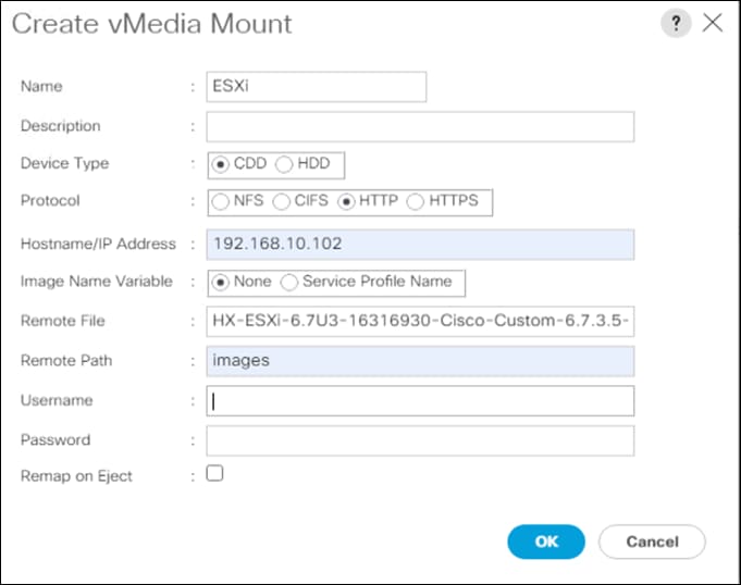
12. Click OK.
13. Select Servers > Service Profile Templates > root > Sub-Organizations > <<HX_ORG>> > Service Template hx-nodes-m5.
14. In the configuration pane, click the vMedia Policy tab.
15. Click Modify vMedia Policy.
16. Chose the HyperFlex vMedia Policy from the drop-down selection and click OK twice.
17. Select Servers > Policies > root > Sub-Organizations > <<HX_ORG>> > Boot Policy HyperFlex.
18. In the navigation pane, expand the section titled CIMC Mounted vMedia.
19. Click the entry labeled Add CIMC Mounted CD/DVD.
20. Select the CIMC Mounted CD/DVD entry in the Boot Order list and click the Move Up button until the CIMC Mounted CD/DVD entry is listed first.
21. Click Save Changes and click OK.
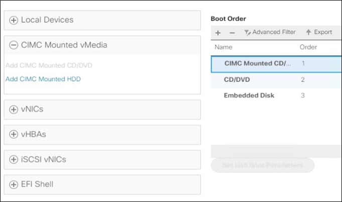
Install ESXi
To begin the installation after modifying the vMedia policy, Boot policy and service profile template, the servers need to be rebooted. To complete the reinstallation, it is necessary to open a remote KVM console session to each server being worked on. To open the KVM console and reboot the servers, follow these steps:
1. In Cisco UCS Manager, click Equipment.
2. Expand Equipment > Rack mounts > Servers > Server 1.
3. In the configuration pane, click KVM Console.
4. The remote KVM Console window will open in a new browser tab. Click Continue to any security alerts that appear and click the hyperlink to start the remote KVM session.
5. Repeat Steps 2-4 for all additional servers whose console you need to monitor during the installation.
6. In Cisco UCS Manager, click the Equipment button on the left-hand side.
7. Expand Equipment > Rack-Mount Servers > Servers.
8. In the configuration pane, click the first server to be rebooted, then shift+click the last server to be rebooted, selecting all the servers.
9. Right-click and select Reset.
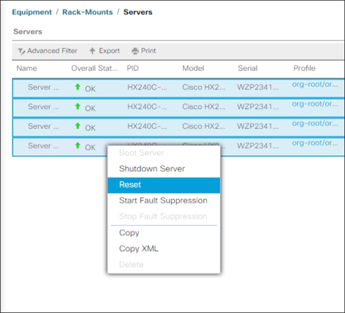
10. Click OK.
11. Select Power Cycle and click OK.
12. Click OK. The servers you are monitoring in the KVM console windows will now immediately reboot, and boot from the remote vMedia mount. Alternatively, the individual KVM consoles can be used to perform a power cycle one-by-one.
13. When the server boots from the installation ISO file, you will see a customized Cisco boot menu. In the Cisco customized installation boot menu, select “HyperFlex Converged Node – HX PIDs Only” and press Enter.
14. Enter “ERASE” in all uppercase letters, and press Enter to confirm and install ESXi.
15. The ESXi installer will continue the installation process automatically, there may be error messages seen on screen temporarily, but they can be safely ignored. When the process is complete, the standard ESXi console screen will be seen.
Undo vMedia and Boot Policy Changes
When all the servers have booted from the remote vMedia file and begun their installation process, the changes to the boot policy need to be quickly undone, to prevent the servers from going into a boot loop, constantly booting from the installation ISO file. To revert the boot policy settings, follow these steps:
1. Select Servers > Policies > root > Sub-Organizations > <<HX_ORG>> > Boot Policy HyperFlex.
2. Select the CIMC Mounted CD/DVD entry in the Boot Order list and click Delete.
3. Click Save Changes and click OK.
The changes made to the vMedia policy and service profile template may also be undone once the ESXi installations have all completed fully, or they may be left in place for future installation work.
Cisco HyperFlex systems are ordered with a factory pre-installed configuration. This factory integration work will deliver the HyperFlex servers with the proper firmware revisions pre-set, a copy of the VMware ESXi hypervisor software pre-installed, and some components of the Cisco HyperFlex software already pre-staged. Once on site, the final steps to be performed are reduced and simplified due to the already completed factory work. As outlined in the previous section, installation of the Cisco HyperFlex system can be done via a deployable HyperFlex installer virtual machine from an OVA file. Another option to install Cisco HyperFlex system is using the Cisco Intersight cloud management platform or Cisco Intersight Virtual Appliance, wherein the HyperFlex installer function is delivered with no need for the users to have their own installer virtual machine.
Use the following procedures to deploy and configure a 2-node Cisco HyperFlex Edge system from Cisco Intersight Virtual Appliance. The procedures describe how to deploy and run an HX Data Platform configuration where an external vCenter appliance has already been installed and available on an existing ESXi host. Although using an external vCenter appliance is used as an example for this solution, embedded VMware vSphere vCenter is also supported via a separate procedure.
The complete flow of the installation process is shown in Figure 89.
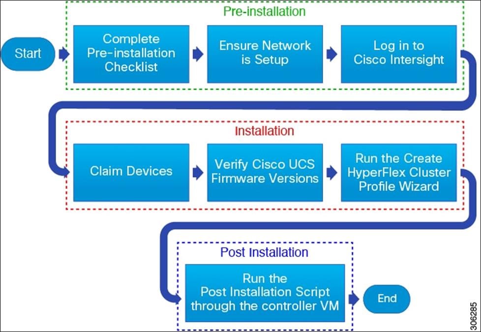
Ensure that the system meets the installation and configuration requirements before you begin to install Cisco HyperFlex Edge clusters. Refer to the Preinstallation Checklist for Cisco HX Edge for detailed preinstallation requirements.
The complete installation process consists of eight steps:
1. Complete the preinstallation checklist.
2. Change adapter MLOM network configuration in CIMC.
3. Ensure network is up and running.
4. Log in to Cisco Intersight.
5. Claim Devices.
6. Verify Cisco UCS Firmware versions.
7. Run the Create HyperFlex Cluster Profile Wizard.
8. Run the post installation script through the controller VM.
Change Adapter MLOM Configuration for 25-Gigabit
Over the past three decades as we transitioned from 10Mbps to 25Gbps Ethernet we’ve required many innovations to support these greater speeds. The latest of these being Forward Error Correction (FEC). The intent of FEC is to reduce the bit error rate (BER) as the cable length increases. For the Cisco UCS VIC 1400 FEC mode is applicable only for 25G link speed. On the VIC 14xx adapters, FEC mode set on the adapter must match the FEC mode of the switch. Otherwise the link does not work. For the current configuration we already set FEC mode fc-fec (cl74) on the Cisco Nexus 93180YC-EX. To get a connection on both sites we need to change the Cisco UCS VIC 1455 within CIMC as well.
To change the FEC mode on all HX Edge node, follow these steps:
1. Log into Cisco IMC on the first HX Edge node.
2. Go to Navigation > Networking > Adapter Card MLOM.
3. Click External Ethernet Interfaces.
4. Click PORT-0 row on Admin FEC Mode and select cl74.
5. Click Save and repeat steps 1-4 for PORT-2.
Claim Devices
To claim the Cisco UCS servers with the HyperFlex Edge, follow these steps:
1. From Intersight Dashboard > Devices, click Claim a New Device.
2. Select From File to claim multiple devices using a file.
3. Create a .csv file with the following configuration:
IMC,172.16.0.100,admin,<your_password>
IMC,172.16.0.101,admin,<your_password>
IMC,172.16.0.102,admin,<your_password>
IMC,172.16.0.103,admin,<your_password>
4. Click Claim and wait for a couple of minutes to get the devices connected with Cisco Intersight.
5. Click Servers to see the discovered UCS servers.
Verify Firmware Version for HyperFlex Edge Nodes
To verify the Firmware version all Cisco HyperFlex Edge nodes, go to Equipment > Servers, search for HX220c and check the Firmware Version.
Configure HyperFlex Edge Cluster
Both remote offices in our solution require a Cisco HyperFlex Edge Cluster and a datastore for CTERA. With the following steps you’ll create both cluster and a datastore with 200 GB.
General Configuration
To configure a HyperFlex Edge Cluster in Intersight, follow these steps:
1. Log into Cisco Intersight and click Profiles.
2. Click the HyperFlex Cluster Profiles tab and click Create HyperFlex Cluster Profile.
3. In the General page click Organization.
4. Type in a Name of the cluster.
5. Click HyperFlex Data Platform Version.
6. Select Cisco HyperFlex Edge for Type.
7. Add a Description and click Next.
Cluster Configuration
In the Cluster Configuration page, complete the following fields:
Security
1. Leave Hypervisor Admin as root.
2. Select the hypervisor on this node uses the factory default password and fill in the Hypervisor Password and the Controller VM Admin Password.
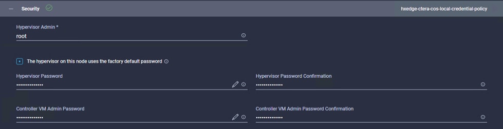
DNS, NTP, and Timezone
1. Select the Timezone, DNS Suffix, DNS and NTP Servers.
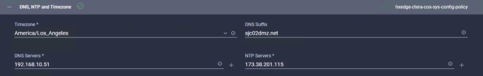
vCenter
1. Type in the vCenter FQDN or IP, vCenter Username, vCenter Password and vCenter Datacenter Name.
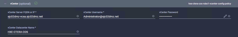
Storage Configuration
1. Click Clean up Disk Partitions.

Auto Support
1. If required, click Auto Support.
IP & Hostname
1. Enter the Hostname Prefix.
2. Enter the Management Network Starting and Ending IP, Subnet Mask and Network Gateway.
3. Enter the Controller VM Management Network Starting and Ending IP, Subnet Mask and Network Gateway.
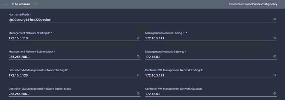
Network Configuration
1. Select Uplink Speed 10G+ (HyperFlex Edge).
2. Enter a MAC Prefix Starting and Ending Address.
3. Enter a Management Network VLAN ID.
4. Retain Jumbo Frames.
HyperFlex Storage Network
1. Enter the Storage Network VLAN ID.
2. Click Next.
Nodes Assignment
1. Select two of the available HyperFlex Edge nodes in the window and click Next.
Nodes Configuration
1. Enter the Cluster Management IP Address and the MAC Prefix Address and validate the details for each node.
2. Click Next.
Summary
1. Verify the details of your configuration and click Validate. Intersight will download the HyperFlex Installer image and HyperFlex Data Platform packages to validate the configuration.
Results
1. Check the results for any errors. If there are no errors, then click Validate & Deploy.
2. When the cluster is deployed you can find the current status under HyperFlex Clusters.
3. Repeat steps 1 and 2 for the other cluster with the following changes:
· Type in another Name for the profile
· Type in another Hostname Prefix.
· Use another IP address range for the Management Network and the Controller VM Network.
· Use a different MAC Prefix range.
· Use a different Management and Storage Network VLAN ID.
· Select the remaining two HyperFlex Edge nodes.
· Choose a different Cluster Management IP Address and MAC Prefix Address.
Post-Install Configuration Cisco HyperFlex Edge
Prior to putting a new HyperFlex Edge cluster into production, a few post-install tasks must be completed. To automate the post installation procedures and verify the HyperFlex cluster configuration, a post_install script has been provided on the HyperFlex Controller VMs. To run this script, follow these steps:
1. SSH to the cluster management IP address of the first HyperFlex Edge cluster and login using username and the controller VM password provided during installation. Verify the cluster is online and healthy using “stcli cluster info” or “stcli cluster storage-summary”.
root@SpringpathControllerP0AA8PR79G:~# stcli cluster storage-summary
address: 169.254.1.20
name: HXE-CTERA-COS-ROBO1
state: online
uptime: 0 days 13 hours 55 minutes 40 seconds
activeNodes: 2 of 2
compressionSavings: 0.0%
deduplicationSavings: 0.0%
freeCapacity: 6.0T
healingInfo:
inProgress: False
resiliencyInfo:
messages:
Storage cluster is healthy.
state: 1
nodeFailuresTolerable: 1
cachingDeviceFailuresTolerable: 1
persistentDeviceFailuresTolerable: 1
zoneResInfoList: None
spaceStatus: normal
totalCapacity: 6.0T
totalSavings: 0.0%
usedCapacity: 55.8G
zkHealth: online
arbitrationServiceState: online
clusterAccessPolicy: lenient
dataReplicationCompliance: compliant
dataReplicationFactor: 2
2. Run the following command in the shell, and press Enter:
/usr/share/springpath/storfs-misc/hx-scripts/post_install.py
3. Select the first post_install workflow type – New/Existing Cluster.
4. Enter the HX Storage Controller VM root password for the HX cluster (use the one entered during the HX Cluster installation).
5. Enter the vCenter server username and password.
6. Enter ESXi host root password (use the one entered during the HX Cluster installation).
7. You must license the vSphere hosts through the script or complete this task in vCenter before continuing.
8. Failure to apply a license will result in an error when enabling HA or DRS in subsequent steps. Enter “n” if you have already registered the license information in vCenter.
9. Enter “y” to enable HA/DRS.
10. Enter “y” to disable the ESXi hosts’ SSH warning.
11. Add the vMotion VMkernel interfaces to each node by entering “y”. Input the netmask, the vMotion VLAN ID, and the vMotion IP addresses for each of the hosts as prompted.
12. You may add VM network portgroups for guest VM traffic. Enter “n” to skip this step and create the portgroups manually in vCenter. Or if desired, VM network portgroups can be created and added to the vm-network vSwitch. This step will add identical network configuration to all nodes in the cluster.
13. Enter “y” to run the health check on the cluster.
14. A summary of the cluster will be displayed upon completion of the script. Make sure the cluster is healthy.
root@SpringpathControllerP0AA8PR79G:~# /usr/share/springpath/storfs-misc/hx-scripts/post_install.py
Select post_install workflow-
1. New/Existing Cluster
2. Expanded Cluster (for non-edge clusters)
3. Generate Certificate
Note: Workflow No.3 is mandatory to have unique SSL certificate in the cluster.
By Generating this certificate, it will replace your current certificate.
If you're performing cluster expansion, then this option is not required.
Selection: 1
Logging in to controller localhost
HX CVM admin password:
Getting ESX hosts from HX cluster...
vCenter URL: 192.168.10.50
Enter vCenter username (user@domain): Administrator@sjc02dmz.net
vCenter Password:
Found datacenter HXE-CTERA-COS
Found cluster HXE-CTERA-COS-ROBO1
post_install to be run for the following hosts:
172.16.5.110
172.16.5.111
Enter ESX root password:
HX Edge configuration detected
Uplink speed is detected as: 25G
Uplink count is detected as: 2
Enter vSphere license key? (y/n) n
Enable HA/DRS on cluster? (y/n) y
Successfully completed configuring cluster HA.
Successfully completed configuring cluster DRS.
Disable SSH warning? (y/n) y
Add vmotion interfaces? (y/n) y
Netmask for vMotion: 255.255.255.0
VLAN ID: (0-4096) 107
vMotion IP for 172.16.5.110: 172.16.7.120
Adding vmotion-107 to 172.16.5.110
Adding vmkernel to 172.16.5.110
vMotion IP for 172.16.5.111: 172.16.7.121
Adding vmotion-107 to 172.16.5.111
Adding vmkernel to 172.16.5.111
Add VM network VLANs? (y/n) y
Port Group Name to add (VLAN ID will be appended to the name in ESXi host): hx-client
VLAN ID: (0-4096) 102
Adding hx-client-102 to 172.16.5.110
Adding hx-client-102 to 172.16.5.111
Add additional VM network VLANs? (y/n) n
Run health check? (y/n) y
Validating cluster health and configuration...
Cluster Summary:
Version - 4.0.2b-35410
Model - HX220C-M5SX
Health - HEALTHY
ASUP enabled – False
15. Repeat steps 1-14 for the other HyperFlex Edge cluster but with different IP address and VLAN for the vMotion interface.
The initial configuration of the Cisco HyperFlex Cluster is now finished. In the next step you’ll create a datastore for CTERA on each HyperFlex Edge cluster.
Create Datastore for CTERA Edge on Cisco HyperFlex Edge Clusters
Create a datastore for storing the virtual machines. This task can be completed by using the vSphere Web Client HX plugin, or by using the HyperFlex Connect HTML management webpage. To configure a new datastore via the HyperFlex Connect webpage, follow these steps:
1. Use a web browser to open the HX cluster IP management URL of the first HyperFlex Edge cluster.
2. Enter a local credential, or a vCenter RBAC credential with administrative rights for the username, and the corresponding password.
3. Click Login.
4. Click Datastores and click Create Datastore.
5. In the popup, enter the Datastore Name and size. For most applications, leave the Block Size at the default of 8K. Only dedicated Virtual Desktop Infrastructure (VDI) environments should choose the 4K Block Size option.
6. Click Create Datastore.
7. Repeat steps 1-6 for the other HyperFlex Edge cluster.
Smart Licensing
For licensing both HyperFlex Edge clusters, follow the steps in section Smart Licensing.
ESXi Hypervisor Installation
HX Edge nodes come from the factory with a copy of the ESXi hypervisor pre-installed, however there are scenarios where it may be necessary to redeploy or reinstall ESXi on an HX Edge node. In addition, this process can be used to deploy ESXi on rack mount or blade servers that will function as HX compute-only nodes. The HyperFlex system requires a Cisco custom ESXi ISO file to be used, which has Cisco hardware specific drivers pre-installed, and customized settings configured to ease the installation process. The Cisco custom ESXi ISO file is available to download at cisco.com.
ESXi Kickstart ISO
The HyperFlex custom ISO is based on the Cisco custom ESXi 6.7 Update 3 ISO release “HX-ESXi-6.7U3-16316930-Cisco-Custom-6.7.3.5-install-only.iso” and is available on the Cisco website:
https://software.cisco.com/download/home/286305544/type/286305994/release/4.0(2b)
The custom Cisco HyperFlex ESXi ISO will automatically perform the following tasks with no user interaction required:
· Accept the End User License Agreement
· Configure the root password to: Cisco123
· Install ESXi to the internal mirrored Cisco FlexFlash SD cards, or the internal M.2 SSD
· Set the default management network to use vmnic0, and obtain an IP address via DHCP
· Enable SSH access to the ESXi host
· Enable the ESXi shell
· Enable serial port com1 console access to facilitate Serial over LAN access to the host
· Configure the ESXi configuration to always use the current hardware MAC address of the network interfaces, even if they change
· Rename the default vSwitch to vswitch-hx-inband-mgmt
Reinstall HX Cluster
If a Cisco HyperFlex cluster needs to be reinstalled, contact your local Cisco account or support team in order to be provided with a cluster cleanup guide. Note that the process will be destructive and result in the loss of all the VMs and all the data stored in the HyperFlex distributed filesystem. A high-level example of a HyperFlex rebuild procedure is as follows:
1. Clean up the existing environment by:
- Delete existing HX virtual machines and HX datastores.
- Destroy the HX cluster.
- Remove the HX cluster from vCenter.
- Remove vCenter MOB entries for the HX extension.
- Do a fresh ESXi re-installation on all the HyperFlex Edge nodes.
- In Cisco Intersight, associate the HyperFlex Cluster Profile with the edge nodes and proceed with redeployment.
To install ESXi hosts, it is necessary to open a remote KVM console session to each server being worked on. To open the KVM console and reboot the servers, follow these steps:
1. Download the latest HyperFlex custom ISO file from Cisco website to the local machine.
2. Launch KVM from CIMC management console for every server.
3. In the KVM Console, click Virtual Media, then Activate Virtual Devices.
4. Accept the unencrypted session for Virtual Media and apply the response.
5. When the session of Activate Virtual Devices is completed, click Map CD/DVD.
6. Browse to the folder where the downloaded HyperFlex custom ISO image is saved, select that file. Click Map Device to continue.
7. Click Power, choose Power Cycle System to reboot the server.
8. Click Yes to continue.
9. The server you are monitoring in the KVM console window will now immediately reboot. During booting, press F6 to enter the Boot Menu.
10. Select Cisco vKVM-Mapped vDVD1.24 device as boot device.
11. The server boots from the installation ISO file. You will see a customized Cisco boot menu. In the Cisco customized boot menu, select “HyperFlex Converged Node – HX PIDs Only” and press Enter.
12. Enter ERASE then press Enter. The ESXi installer will continue the installation process automatically. When the process is complete, the standard ESXi console screen displays.
13. Repeat Steps 3-12 for all additional HyperFlex Edge servers.
The formal setup and configuration of Cisco HyperFlex and Cisco Intersight is now finished. The next step is to install and configure CTERA Portal on Cisco HyperFlex Data Platform and CTERA vGateway on Cisco HyperFlex Edge.
Install CTERA Portal
This section describes how to install CTERA Portal on each server.
Import the CTERA Portal OVA File
Contact CTERA and request the latest ESXi Edge Filer OVA file.
To install the Edge Filer using the vSphere Host Client, follow these steps:
![]() When using the vSphere Host Client, since the OVA file is larger than 2GB, you must unpack the OVA file, which includes the OVF file, VMDK and MF files. Use the OVF and VMDK files to deploy the portal.
When using the vSphere Host Client, since the OVA file is larger than 2GB, you must unpack the OVA file, which includes the OVF file, VMDK and MF files. Use the OVF and VMDK files to deploy the portal.
1. In the vSphere Host Client, right-click Virtual Machines and select Create/Register VM, choose Deploy a virtual machine from an OVF or OVA file and click Next. The New virtual machine wizard is displayed.

2. Enter a name for the portal and drag the OVF and VMDK files to the file area.
3. Click Next.
4. Continue through the wizard specifying the following information, as required for your configuration:
a. Select “HX-CTERA-COS” as the computer resource
b. Select CTERA as the datastore to use for the portal.
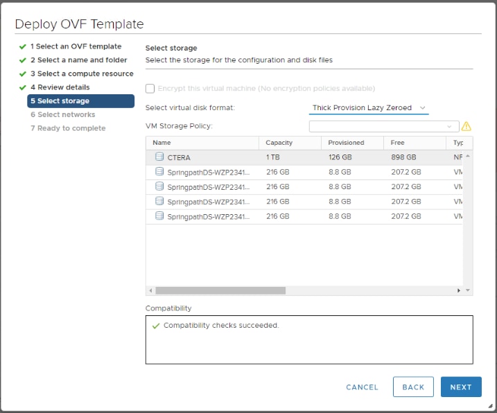
5. The disk provisioning for the virtual disk. In in-house testing the choice of format, Thin or Thick provisioning made no difference to the portal performance. Refer to the VMware documentation for an explanation of these formats.
6. Click Finish. The portal is created and powered on.
7. Right-click the portal virtual machine and select Edit Settings. The configuration is displayed for the portal.
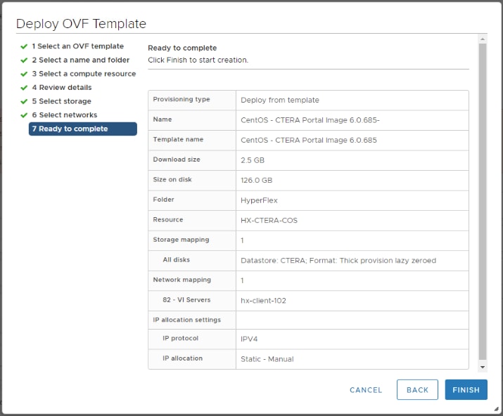
8. Expand the Network Adapter 1 item and verify that the Adapter Type is VMXNET 3.
![]() If the adapter type is not VMXNET 3, power off the virtual machine and set the adapter type to VMXNET 3 before powering the virtual machine back on.
If the adapter type is not VMXNET 3, power off the virtual machine and set the adapter type to VMXNET 3 before powering the virtual machine back on.
Prepare for Production Deployment
· When deploying a main database server or a catalog node to production: It is recommended to remove the default 50GB and 60GB VMDKs included in the CTERA Portal OVA, and attach a VMDK sized 2% of the overall cloud storage you intend to allocate for the service. Prior to going to production, contact CTERA Support to evaluate whether the attached drive's performance meets CTERA's main database and catalog node performance requirements.
· When deploying an application server to production: It is recommended to remove the default 60GB VMDK included in the CTERA Portal OVA.
· When deploying a document preview server to production: You may keep the existing drives included in the CTERA Portal OVA.
Log into the CTERA Portal Server
To log into the portal server, follow these steps:
1. Log in as root, using SSH or through the console.
2. The default password is ctera321.
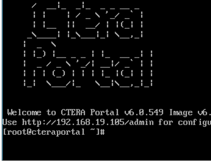
Configure Network Settings
By default, the CTERA Portal server obtains an IP address using DHCP. In a production environment it is recommended to use a static IP address. If your infrastructure includes more than one network, you must configure CTERA Portal for the appropriate network. You configure network settings by using nmtui, the built-in network manager.
To use nmtui, follow these steps:
1. Log in as root, using SSH or through the console.
2. Run the following command: nmtui. The NetworkManager TUI screen is displayed.
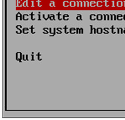
3. Use your keyboard arrows or the TAB key to navigate between options.
Change the CTERA Portal Server's Hostname
To change the CTERA Portal server's hostname, follow these steps:
1. In nmtui, navigate to Set system hostname and press Enter.
2. The Set Hostname screen opens, displaying the current portal hostname. In the field provided, type the server hostname.
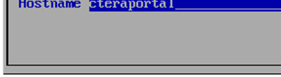
3. In the field provided, enter the server hostname.
4. Navigate to OK and press Enter. A confirmation message is displayed.
5. Press Enter. The new hostname is configured.
6. Navigate to Quit and press Enter to exit nmtui.
7. You need to reboot the system for the change to take effect. You can reboot the system by entering the command: reboot
Configure a Network Interface
To list all network interfaces, follow this step:
1. Run the command: ifconfig
To configure a static IP address for a network interface, follow these steps:
1. In nmtui, navigate to Edit a connection and press Enter. The following window opens, displaying all network adapters attached to the CTERA Portal server.
2. Navigate to the network adapter for which you want to set a static IP address and press Enter. The Edit connection window is displayed.
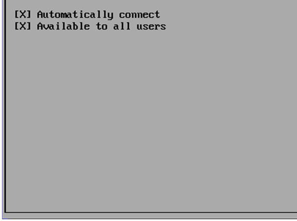
3. Navigate to Automatic next to IPv4 CONFIGURATION, press Enter, and then click Manual.
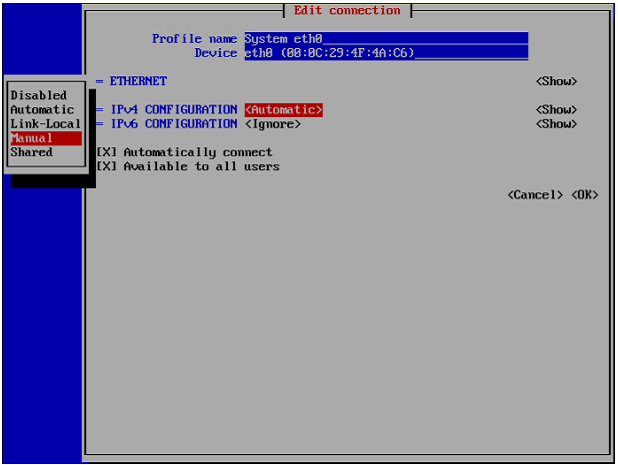
4. Navigate to Show next to IPv4 CONFIGURATION and press Enter. Additional fields are displayed.
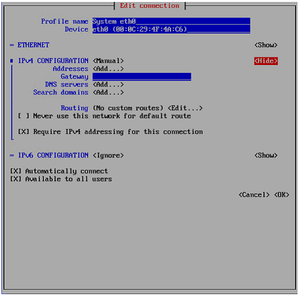
5. Navigate to Add next to Addresses and press Enter.
6. Type “170.160.90/24” as the static IP address.
7. To configure a default gateway for the current network interface, navigate to Gateway, and then type “172.16.2.1” as the IP address of the default gateway.
8. To configure a DNS server, navigate to Add next to DNS servers, press Enter, and then enter the “192.168.10.51 ” as IP address of the DNS server.
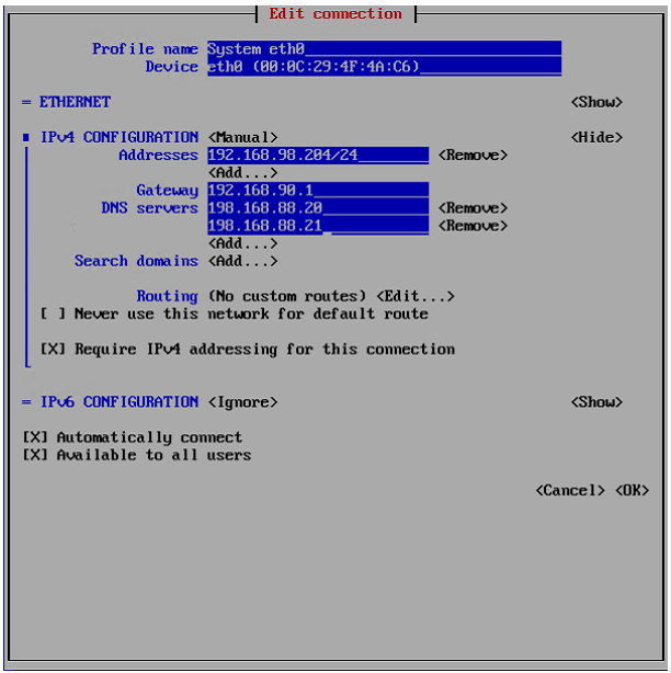
9. Navigate to OK and press Enter.
10. Navigate to Quit and press Enter to exit nmtui.
11. Restart the network service by typing the command: service network restart
Your changes take effect.
Configure a Default Edge Filer
To set a default edge filer for the CTERA Portal server:
1. Run the following command:
echo "GATEWAY=default_gateway_ip_address" > /etc/sysconfig/network
Where default_gateway_ip_address is your default gateway IP address “172.16.0.1”..
For example:
echo "GATEWAY=172.16.0.1" > /etc/sysconfig/network
2. Restart the network service, by running the following command: service network restart Your changes take effect.
Initialize the Storage Pool
To create a new LVM storage pool, follow these steps:
1. Run the following command: fdisk –l
2. In the output, copy the name of the second disk displayed. In the following example, the second disk is named xvdf.
[root]# fdisk -l
Disk /dev/xvde: 6442 MB, 6442450944 bytes
255 heads, 63 sectors/track, 783 cylinders
Units = cylinders of 16065 * 512 = 8225280 bytes
Sector size (logical/physical): 512 bytes / 512 bytes
I/O size (minimum/optimal) : 512 bytes / 512 bytes
Disk identifier: 0xaae7682d
Device Boot Start End Blocks Id System
/dev/xvde1 * 1 783 6289416 83 Linux
Disk /deve/xvdf: 107.4 GB, 107374182400 bytes
255 heads, 63 sectors/track, 13054 cylinders
Units = cylinders of 16065 * 512 = 8225280 bytes
Sector size (logical/physical): 512 bytes / 512 bytes
I/O size (minimum/optimal) : 512 bytes / 512 bytes
Disk identifier: 0x00000000
Disk /dev/xvdf doesn't contain a valid partition table
[root]#
3. Run the following command: ctera-storage-util.sh create_storage <2nd_vol_name> Where <2nd_vol_name> is the name of the volume copied in the previous step. For example:
ctera-storage-util.sh create_storage xvdf
4. Run the following command to restart the portal: ctera-portal-manage.sh restart
5. Run the following command to ensure the volume is OK: ctera-portal-manage.sh status. The following lines appear in the output:
CTERA Portal: Starting
...
Database Data Directory: Ready
The LVM storage pool is now initialized.
Install the Edge Filer (Gateway) On HyperFlex using vSphere Client
Installing a CTERA Edge Filer involves creating and configuring a virtual machine and then performing an initial setup.
In this section:
· Install the Gateway on ROBO1
· Configure a CTERA Portal as a Precondition to Setting Up the Filer
Install the Gateway on ROBO1
To install the gateway using the HyperFlex vSphere Client:
1. In the HyperFlex vSphere Client, create a virtual machine by deploying an OVF template.
2. Select “HXE-CTERA-COS” In the wizard right-click deploy OVF, click Choose Files, and browse to the CTERA gateway OVA file.
3. Click NEXT.
4. Continue through the wizard specifying the following information, as required for your configuration:
a. A name to identify the gateway in vCenter, select “HXE-CTERA-COS-ROBO1” as the computer resource.
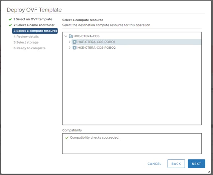
b. Select “CTERA Edge ROBO1” for the Edge Filer Storage.
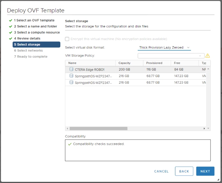
c. The virtual disk format for the gateway software and the datastore to use for this software.
![]() Refer to the VMware documentation for an explanation of the disk provisioning formats.
Refer to the VMware documentation for an explanation of the disk provisioning formats.
d. Select “hx-client-102” as the network resource.

5. Review the configuration details and click FINISH. The gateway is created and powered off.
6. With the virtual machine powered off, right-click the gateway and select Edit Settings.
7. The configuration is displayed for the Virtual Gateway.
a. Change the CPU, Memory, and other virtual machine settings, based on the company policy and the gateway license.
§ For an EV16 license the maximum number of CPUs is 4 and the maximum RAM is 8GB.
§ For an EV32 license the maximum number of CPUs is 8 and the maximum RAM is 16GB.
§ For an EV64 license the maximum number of CPUs is 16 and the maximum RAM is 32GB.
§ For an EV128 license the maximum number of CPUs is 32 and the maximum RAM is 64GB.
b. Click ADD NEW DEVICE and select Hard Disk from the drop-down menu.
c. Specify the disk size. When configured as a Caching Gateway, CTERA recommends storage at least 20% of the Portal Global Name Space. Whenever possible, CTERA recommends that the maximum storage is defined as a single disk. The maximum storage is dependent on the license.
§ For an EV16 license the maximum is 16TB.
§ For an EV32 license the maximum is 32TB.
§ For an EV64 license the maximum is 64TB.
§ For an EV128 license the maximum is 128TB.
![]() A VMware ESXi host limits disks to a maximum of 62TB. To support storage greater than 62TB, you need to create multiple disks, each less than 62TB and then create a JBOD or RAID0 array in the gateway user interface.
A VMware ESXi host limits disks to a maximum of 62TB. To support storage greater than 62TB, you need to create multiple disks, each less than 62TB and then create a JBOD or RAID0 array in the gateway user interface.
d. Expand the New Hard disk item and set Disk Provisioning.
![]() Refer to VMware documentation for an explanation of the disk provisioning formats.
Refer to VMware documentation for an explanation of the disk provisioning formats.
e. Click OK.
8. Power on the virtual machine.
To set the virtual machine IP address, follow these steps:
1. Access the virtual machine. The following login screen is displayed:

2. Log in with the username setup and no password, as instructed. The console is displayed.
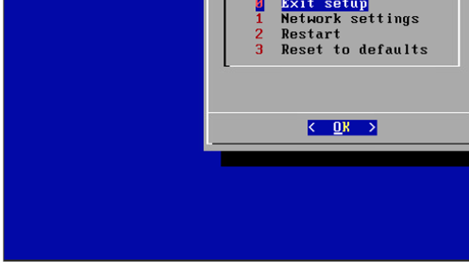
![]() The console might have other options.
The console might have other options.
The IP address for the edge filer is displayed in the top right of the console. You use this IP address to access the edge filer in a browser.
To set a static IP address, follow these steps:
1. Click in the console to transfer the keyboard control to the console and, if necessary, use the arrow keys to scroll to Network settings.
2. Press Enter.
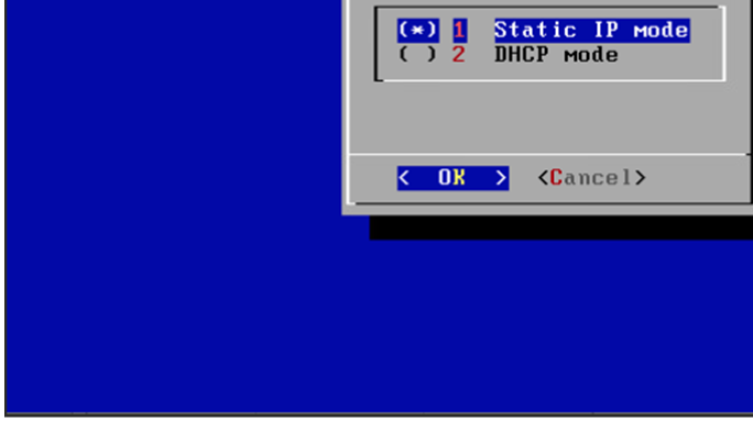
3. Select Static IP mode and press OK.
4. Complete the configuration for static mode by entering the “172.16.2.91” as the static IP, “255.255.255.0” for the netmask, “172.16.2.1” as default gateway IP and the “192.168.10.51” as primary DNS server IPs.
5. Press OK.
6. Repeat steps 1-5 for ROBO2 location with compute resource “HXE-CTERA-COS-ROBO2” and the specific datastore. Use the Ip address “172.16.0.92” for the CTERA Edge Filer.
Configure a CTERA Portal as a Precondition to Setting Up the Filer
Before setting up the Edge Filer, you have to configure the CTERA Portal to which the filer will connect.
To configure the portal, follow these steps:
1. The user account on the portal used to connect the filer to the portal must have read and write administrator permissions to enable syncing folders between the gateway and the portal.
2. Sign into the portal as an administrator and access the administration user interface.
3. Select Settings > User Roles in the navigation pane.
4. The Roles window is displayed.
5. Click Read/Write Administrator and in the Edit Roles window make sure that Access End User Folders is granted.
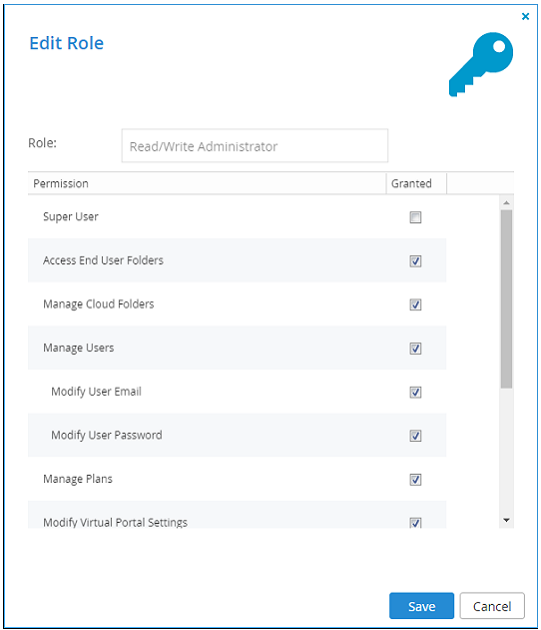
6. Create a designated user as an owner of the cloud folders and data. CTERA recommends creating the owner as a local service account with administrator privileges and not a real user. Once the data is uploaded to the CTERA Portal there is an owner for the data who can get elevated rights.
7. Select Users > Users in the navigation pane.
8. The USERS page is displayed.
9. Click New User.
The New User window is displayed.
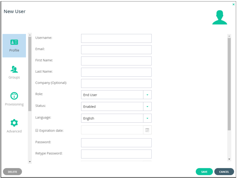
10. Complete the following fields in the Profile option:
- Username – A name for the user's CTERA Portal account.
- Email – An email address.
- First Name – A first name for the service account.
- Last Name – A last name for the service account.
- Role – Select Read/Write Administrator.
- Password/Retype Password – A password for the account.
11. Click SAVE.
Connect IBM COS Storage to CTERA Portal
To connect IBM COS storage to the CTERA portal, follow these steps:
1. Go to the Administration Pane to connect “IBM Cloud Object Storage (S3)”. Please make sure you have the “Access Key ID” and “Secret Access Key” and Select “Direct Mode.”
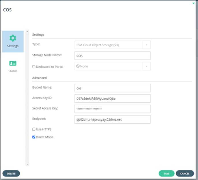
Data Migration
When not using the migration tool, set the folders to share with the same shares configuration as in the original file server, otherwise continue with Initial Edge Filer Setup.
For example, the following team folders exist on a Windows server named SRV2:
To configure the data migration, follow these steps:
1. Create the corresponding folders in the CTERA Portal and then sync them down to the CTERA Edge Filer. Once the folders are synced to the CTERA filer you need to create the shares pointing to these folders via the CTERA filer user interface.
2. Where appropriate, CTERA recommends creating site or company cloud folders. For example, if the migrated data will be used at multiple company sites, with similar share structures at each site, you should create a corporate cloud folder with all the folders that will be shared by all the sites underneath it and in addition have a site folder per site containing all the share folders for the site.
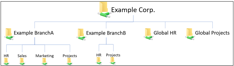
With this structure, you can edit the ACLs for each folder at the top level of the share.
3. Go to Folders > Cloud Drive Folders in the navigation pane.
The Cloud Drive Folders page is displayed.
4. Click New.
![]() You cannot set up an existing folder that already contains files.
You cannot set up an existing folder that already contains files.
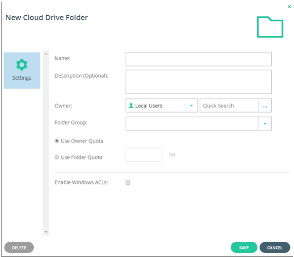
5. Complete the following fields:
- Name – The name for the folder.
- Description – An optional description for the folder.
- Owner – The user who is the owner of the folder.
- Folder Group – A folder group for the folder.
- Check the Enable Windows ACLs check box.
ACL emulation enables files and folders management via standard SMB protocol using Windows Explorer.
6. Click SAVE.
7. Repeat steps 1-6 for all the share folders.
The new folders are added to the Cloud Drive folders.
8. Log into the end user portal with the service account that owns the share folders.
9. Select each folder and click the Share this folder icon ![]() .
.
10. Add the domain users group and click ![]() and choose the Read/write permission.
and choose the Read/write permission.
11. You can add individual users if you don’t want the folder shared with every user from the domain users group.
Initial Edge Filer Setup
Before setting up the gateway, you must configure the portal to which the gateway will connect. After configuring the portal and installing the gateway, you need to perform an initial gateway setup. On first access to the gateway, you set up a gateway administrator and then a wizard guides you through connecting to a portal and storage and user setup. You can skip any of the wizard steps and perform them later, as described in the CTERA Edge Filer (Gateway) Administrator Guide.
If you are installing the edge filer to replace an existing version 6.0.x edge filer, contact CTERA support before performing the initial setup described below.
After this initial gateway setup, the file server structure is synced from the portal to the gateway.
To access the gateway and initial setup, follow these steps:
1. Open any web browser.
2. Enter the gateway's IP address to navigate to the device.
3. When you connect to the web interface for the first time, your browser displays the Welcome to CTERA page.
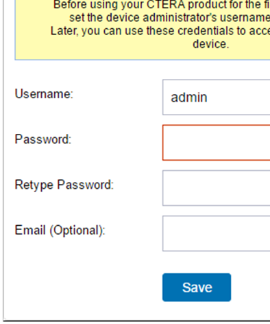
4. Choose a username and password for the administrator. The password must be at least eight characters and must include at least a letter, digit, and special character, such as ~, @, #, $ , %, ^, & , (.
5. You can keep the default username, admin.
6. Optionally, enter an email for receiving notifications regarding the gateway.
7. Click Save.
If the edge filer does not have a disk, the following message window is displayed.
8. Shutdown the gateway and add a disk to the gateway virtual machine.
The Name this Gateway window is displayed.
9. Either keep the gateway default name or enter a new name to identify the gateway and click Next.
10. The administration user interface is displayed to set up the gateway, starting with the Account Details window.
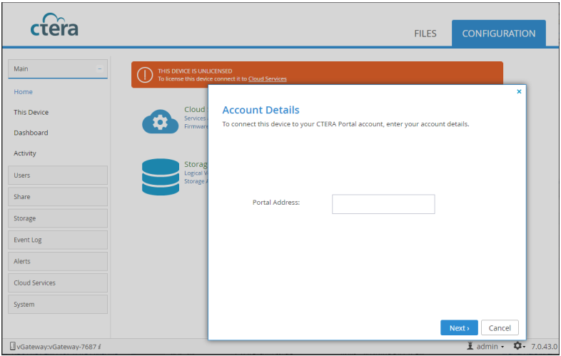
11. You can also change the gateway name after the initial setup, as described in the CTERA Edge Filer (Gateway) Administrator Guide.
12. Enter the DNS name of the CTERA Portal to which you have an account and want to connect the gateway to, in the Portal Address field and click Next.
The Sign in window is displayed.
13. Enter the portal designated user username and password, configured in section Configure a CTERA Portal as a Precondition to Setting Up the Filer to access the portal and click Next.
The Select License window is displayed.
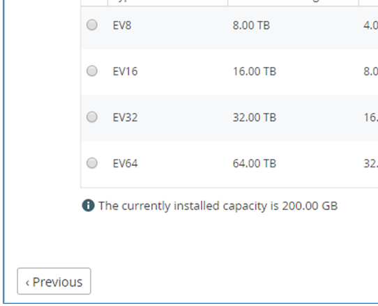
The available storage is displayed.
14. Select the license for the gateway and click Next.
The Select Gateway Mode window is displayed.
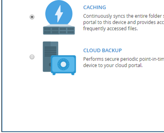
15. If the gateway is not licensed for cloud backup, this step is skipped and the gateway is automatically configured in CACHING mode and the Easy Storage Setup window, step is displayed.
16. Select the primary mode you want to configure for the gateway. This can be changed later, as described in the CTERA Edge Filer (Gateway) Administrator Guide. The modes are:
- CACHING (Caching Gateway) – Provides users with LAN speed access to all the shared cloud folders on the Portal. Shared storage is on the portal in the cloud with stubs saved on the gateway. A stub is a file with a tiny footprint that contains the metadata about the file, such as the file name, size, and modification date. Only the folder and file metadata and not the actual file content is saved locally. Thus, the gateway can have much less physical storage than is made available to users, who have access to both the local edge filer storage and the portal storage. Systems with many file changes, where only some of the files are required locally, don’t overuse bandwidth between the cloud and gateway. Only the required files are passed across the wire. When a user accesses a file stub, the file is opened without delay, by streaming the file content from the cloud. After the download has completed, the file is unstubbed. Any changes to the file are synced back to the portal. Folders that are always required can be pinned, in which case the files in the folders, and not the stubs, are stored on the gateway.
17. If you are replacing an existing file server, set the mode to CACHING.
- CLOUD BACKUP – Provides secure periodic point-in-time backups of selected local folders on the edge filer that are not part of the cloud shared folder. Automated differential backup and restore functions include block-level deduplication, compression, and encryption technologies, ensuring secure and efficient synchronization between the CTERA Edge Filer and the cloud. Backups are encrypted using high-grade AES encryption and encoded to maximize bandwidth utilization. When CLOUD BACKUP is selected, CACHING defaults to disabled. This can be changed in the edge filer user interface.
Cloud files cached with a portal are backed up from the portal. CLOUD BACKUP is used to back up local folders and files.
18. Click Next.
The Easy Storage Setup window is displayed.
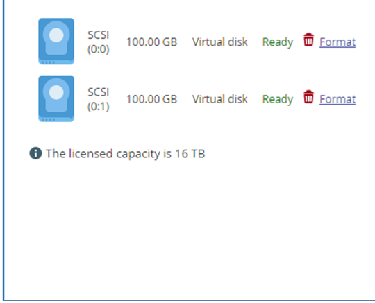
The maximum storage allowed for the gateway license is also displayed.
19. Format the virtual disks. Whenever a new disk is added to the gateway, it should always be formatted.
20. Click Next.
21. If the setup wizard determines that certain storage configuration changes would be beneficial, the Proposed Actions window is displayed describing the recommended changes.
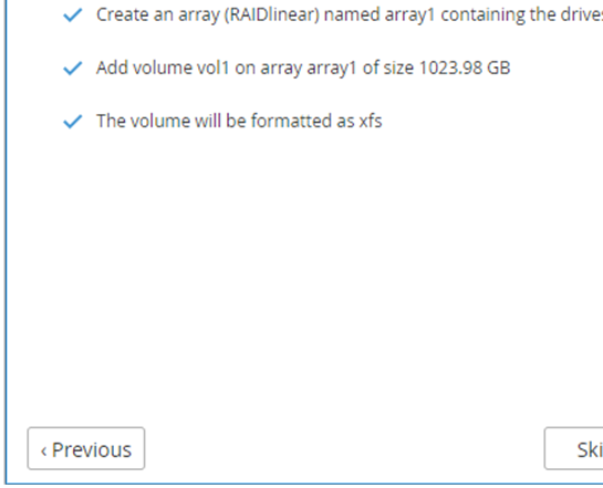
An array is proposed only if the virtual machine has multiple disks.
22. Click Next.
The Join and Active Directory Domain window is displayed.
23. Specify the domain details so that the gateway is populated with the users from your Active Directory domain.
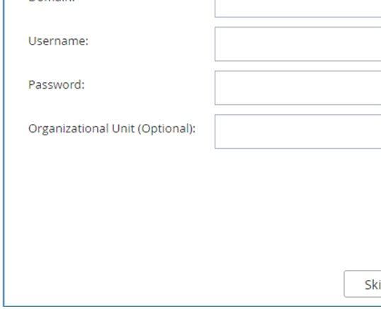
24. Click Next or, if you want to set up Active Directory later, click Skip.
25. The Wizard Completed window is displayed.
26. Click Finish.
27. The CONFIGURATION tab's Main > Home page is displayed.
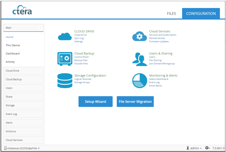
![]() If you selected CLOUD BACKUP, you can enable caching at a later date.
If you selected CLOUD BACKUP, you can enable caching at a later date.
28. Select Main > Dashboard and verify that all the hard disk drives installed in the gateway are available.
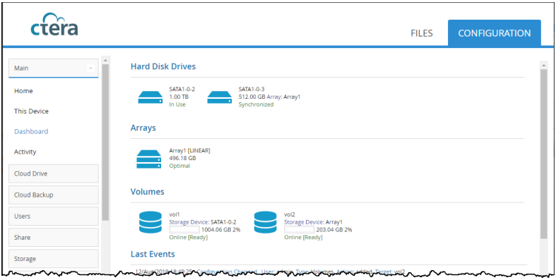
29. You can rerun the wizard by selecting Main > Home and click Setup Wizard.
30. You can migrate a file server to CTERA so that end users who are familiar with a given folder structure and share, while using the file server, continue to see the same folder structure and shares after migration to the gateway.
The following redundancy testing can be performed to verify the robustness of the HyperFlex and HyperFlex Edge system. With the Invisible Cloud Witness provided by Cisco Intersight since HXDP 4.0 release, the need for an external witness node is eliminated for 2-node HyperFlex Edge clusters.
Cisco HyperFlex Invisible Cloud Witness is designed to maintain file system consistency by preventing a “split brain” condition if the nodes in the ROBO cluster loose direct communication with each other and is designed to tolerate failures of the following components:
· WAN/Internet Link
· LAN Connectivity between nodes (may be direct connect)
· Node Availability
These scenarios need to be tested. In addition, removing or adding capacity disks on the HyperFlex and HyperFlex Edge nodes should not cause the system downtime and needs to be tested as well.
Test – HyperFlex Node Failover
To test for the constant availability of the CTERA Portal VM, follow these steps:
1. Locate the CTERA Portal VM in vCenter or ESXi host and click on summary to see on which host the VM is running.
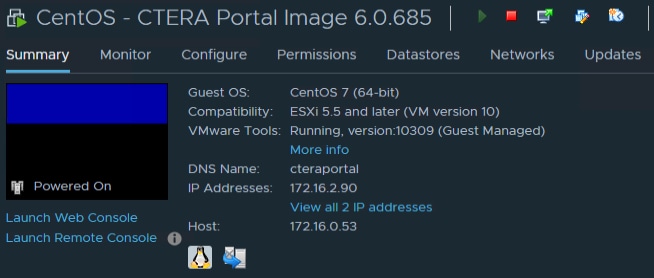
2. Log into Cisco Intersight -> Operate -> HyperFlex Clusters and launch HyperFlex Connect for the HyperFlex Cluster “HX-CTERA-COS”.

3. Check and verify that the cluster is healthy.
4. Start in parallel a ping command to the IP of the CTERA Portal VM.
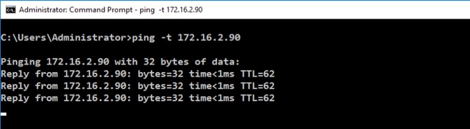
5. In vCenter click on the host and go to Power -> Shut Down. Type in a reason and click OK.
6. Watch the ping window and the HyperFlex Connect screen.
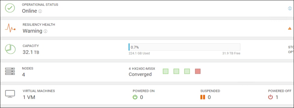
7. After 4 minutes the CTERA Portal VM comes back and the ping command goes through.
8. Check in vCenter the availability of the VM. In the right window under host you can see that the VM now resides on a different host.
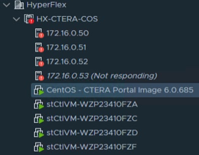
9. Launch UCS Manager and power on the node with Boot Server.
Test – HyperFlex Edge Node Failover
To test for the constant availability of the CTERA Edge Filer VM, follow these steps:
1. Locate the CTERA Edge Filer VM for ROBO1 in vCenter or ESXi host and click Summary to see on which host the VM is running.

2. Log into Cisco Intersight -> Operate -> HyperFlex Clusters and launch HyperFlex Connect for the HyperFlex Cluster “HXE-CTERA-COS-ROBO1”.
3. Check and verify that the cluster is healthy.
4. Start in parallel a ping command to the IP of the CTERA Edge Filer VM.
5. In vCenter click on the host and go to Power -> Shut Down. Type in a reason and click OK.
6. Watch the ping window and the HyperFlex Connect screen.
7. After 4 minutes the CTERA Edge Filer VM comes back and the ping command goes through.
8. Check in vCenter the availability of the VM. In the right window under host you can see that the VM now resides on a different host.
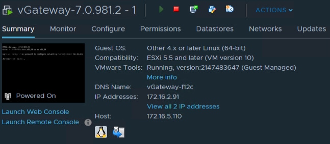
9. Go back to Cisco Intersight and power on the node with Power On.
Test – Network Uplink Failover HyperFlex Node
To test for the network redundancy of the solution, follow these steps:
1. Locate the CTERA Portal VM in vCenter or ESXi host and click on summary to see on which host the VM is running.
2. Log into Cisco Intersight -> Operate -> HyperFlex Clusters and launch HyperFlex Connect for the HyperFlex Cluster “HX-CTERA-COS”.
3. Check and verify that the cluster is healthy.
4. Start in parallel a ping command to the IP of the CTERA Portal VM.
5. In vCenter click on the ESXi host and go to Configure -> Processors and note the Service tag.
6. Log into Cisco UCS Manager and go to Equipment -> Rack-mounts -> Server and look for the serial number you noted. Click the server and go to Hybrid Display. Move your mouse over the Fabric Interconnect connectivity from the server to see the connected port on the Fabric Interconnect.
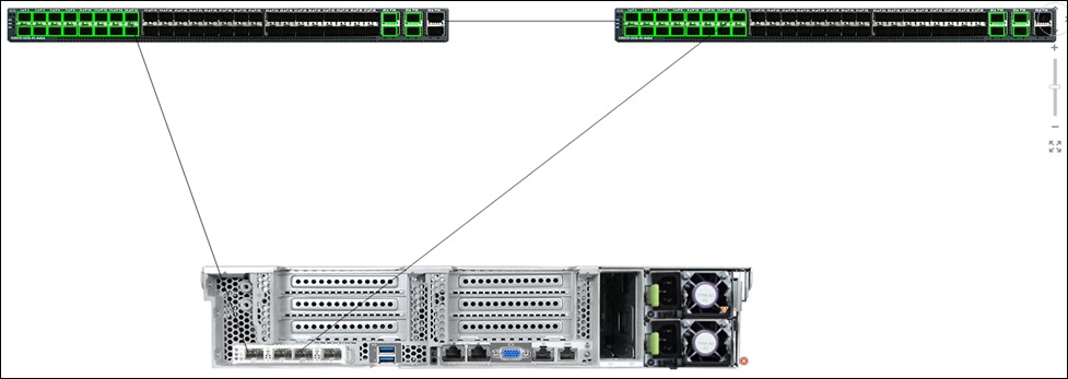
7. Right-click on one of the ports and select Disable.
8. Watch the ping window. There is no failed ping.
9. In vCenter you see an error message that the network uplink redundancy has lost. If you click the vSwitch under Configure you can see a failed vmnic2.
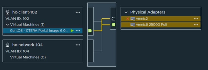
10. Enable the port again in Cisco UCS Manager. Network redundancy gets recovered.
Test – Network Uplink Failover HyperFlex Edge Node
To test for the network redundancy of the solution, follow these steps:
1. Locate the CTERA Edge Filer VM for ROBO1 in vCenter or ESXi host and click Summary to see on which host the VM is running.
2. Log into Cisco Intersight -> Operate -> HyperFlex Clusters and launch HyperFlex Connect for the HyperFlex Cluster “HXE-CTERA-COS-ROBO1”.
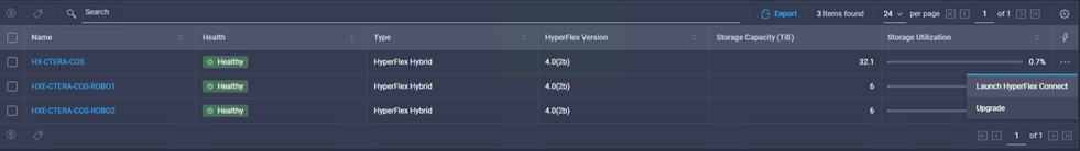
3. Check and verify that the cluster is healthy.
4. Start in parallel a ping command to the IP of the CTERA Edge VM.
5. In vCenter click the ESXi host where the CTERA Edge Filer VM is located. Go to Configure -> Virtual switches and click on the vSwitch for the hx-vm-network to see, which network adapter are used by the VM.
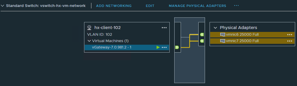
6. Click Physical adapters -> vmnic6 -> CDP and note the Cisco Nexus port where the adapter is connected.
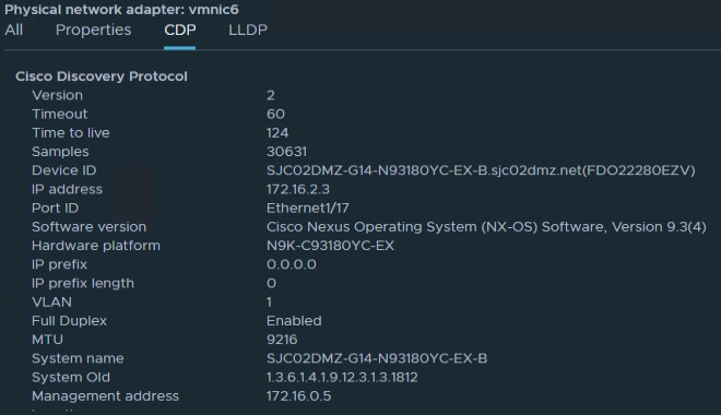
7. Open a CLI window and connect to the above switch and port and shutdown the interface port:
SJC02DMZ-G14-N93180YC-EX-B(config)# show int eth 1/17-20 brief
--------------------------------------------------------------------------------
Ethernet VLAN Type Mode Status Reason Speed Port
Interface Ch #
--------------------------------------------------------------------------------
Eth1/17 1 eth trunk up none 25G(D) --
Eth1/18 1 eth trunk up none 25G(D) --
Eth1/19 1 eth trunk up none 25G(D) --
Eth1/20 1 eth trunk up none 25G(D) --
SJC02DMZ-G14-N93180YC-EX-B(config)# int eth 1/17
SJC02DMZ-G14-N93180YC-EX-B(config-if)# shut
8. Watch the ping window. There is no failed ping.
9. In vCenter you see an error message that the network uplink redundancy has lost. If you click the vSwitch under Configure you can see a failed vmnic6.
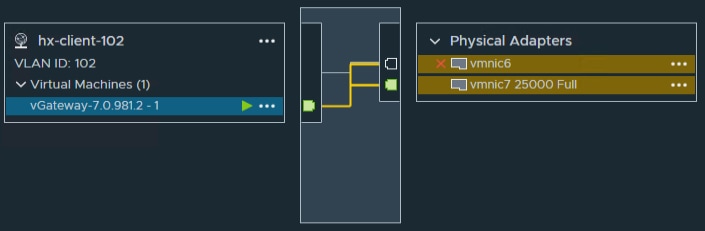
10. Enable the port again. Network redundancy gets recovered.
Test – HyperFlex Node Drive Failure
To test for a failure of a data drive and the cache drive, follow these steps:
1. Locate the CTERA Portal VM in vCenter or ESXi host and click Summary to see on which host the VM is running.

2. Log into Cisco Intersight -> Operate -> HyperFlex Clusters and launch HyperFlex Connect for the HyperFlex Cluster “HX-CTERA-COS”.

3. Check and verify that the cluster is healthy.
4. Start in parallel a ping command to the IP of the CTERA Portal VM.
5. Pull out the first data disk in slot 2 of the HyperFlex Node.
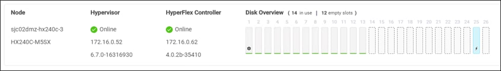
6. Watch the ping window. There is no failed ping.
You will see a warning in Cisco Intersight because of the missing disk.
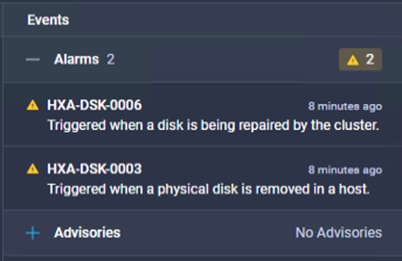
7. In HyperFlex Connect you see a missing disk.
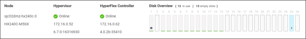
8. Pull the cache disk in slot 25 in addition to the already pulled data disk.
There is again no failed ping. The CTERA Portal VM is still working and available.
There are now a few more warnings in Cisco Intersight.
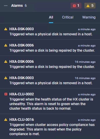
9. In HyperFlex Connect now you see two missing disks.
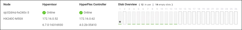
Test – HyperFlex Edge Node Drive Failure
To test for a failure of a data drive and the cache drive on a HyperFlex Edge Node, follow these steps:
1. Locate the CTERA Edge Filer VM in vCenter or ESXi host and click on summary to see on which host the VM is running.
2. Log into Cisco Intersight -> Operate -> HyperFlex Clusters and launch HyperFlex Connect for the HyperFlex Cluster “HXE-CTERA-COS-ROBO1”.

3. Check and verify that the cluster is healthy.
4. Start in parallel a ping command to the IP of the CTERA Edge Filer VM.
5. Pull out the first data disk in slot 3 of the HyperFlex Node.
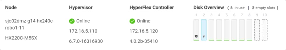
6. Watch the ping window. There is no failed ping.
You will see a warning in Cisco Intersight because of the missing disk.
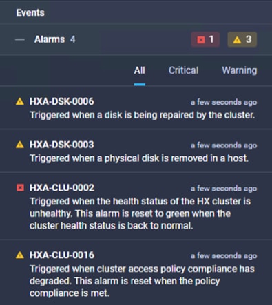
7. In HyperFlex Connect you see a missing disk.
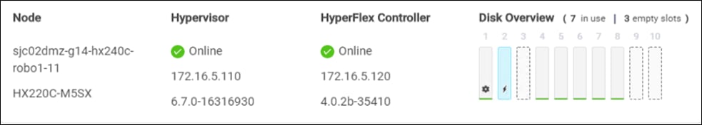
8. Pull the cache disk in slot 2 in addition to the already pulled data disk.
There is again no failed ping. The CTERA Edge Filer VM is still working and available.
There are now a few more warnings in Cisco Intersight.
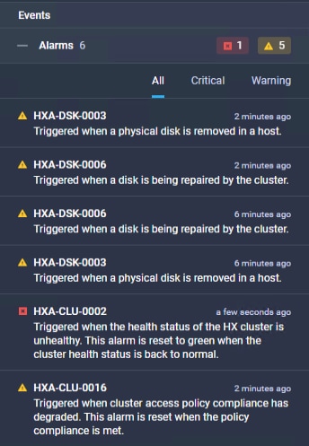
In HyperFlex Connect now you see two missing disks.
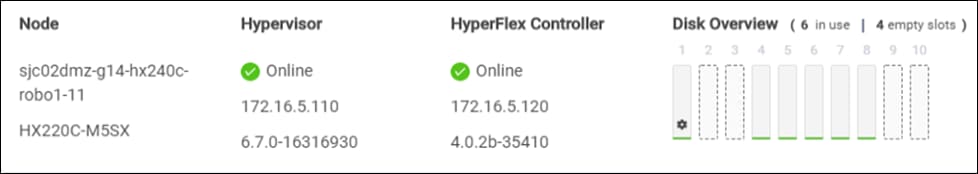
The cluster still operates normally.
You have now finished all redundancy testing and have validated that the solution is working.
The CTERA, IBM, and Cisco HyperFlex solution provides enterprises, government and defense agencies, and other leading organizations a quick and easy way to consolidate traditional IT infrastructure and to modernize how users store, access, collaborate, and protect files. With centralized management and automation, military grade security, and high-performance solutions, CTERA, IBM, and Cisco facilitate next-generation hyperconverged solutions that address several key enterprise IT digital transformation initiatives.
Cisco and IBM are collaborating to offer customers a scalable object storage solution for unstructured data. Together with the Cisco UCS platform, IBM COS can deliver a fully enterprise-ready solution that can manage different workloads and still remain flexible. IBM COS is a software-defined storage that is designed to create unbounded scale-out storage systems that converge the storage of petabyte-scale data from multiple applications and use cases, including both object and file-based applications. The Cisco UCS S3260 Storage Server is an excellent platform to use with the main types of object and file workloads, such as capacity- and performance-optimized workloads.
Cisco UCS Infrastructure provides computing, storage, connectivity, and unified management features, simplifies deployment, and offers a dependable, massively scalable integrated infrastructure that delivers predictable performance and high availability for the solution. Cisco leads the industry in simplified management and automation and is well equipped to lead the industry into the next generation of lifecycle management capabilities. Cisco Intersight SaaS simplifies lifecycle management, making daily tasks easier for the development and operations teams. It scales to support whatever quantity of infrastructure and wherever it gets deployed.
Oliver Walsdorf, Technical Marketing Engineer for Software Defined Storage, Computer Systems Product Group, Cisco Systems, Inc.
Oliver has more than 20 years of storage experience, working in different roles at different storage vendors, and is now an expert for software-defined storage solutions at Cisco. For the past six years Oliver was focused on developing storage solutions at Cisco. He now works on IBM COS, develops co-solutions with IBM for the overall storage market and published several Cisco documents. With his focus on SDS he drives the overall attention in the market for new technologies. In his leisure time, Oliver enjoys hiking with his dog and motorcycling.
Acknowledgements
For their support and contribution to the design, validation, and creation of this Cisco Validated Design, we would like to acknowledge the following for their significant contribution and expertise that resulted in developing this document:
· Chris O’Brien, Cisco Systems, Inc.
· Jawwad Memon, Cisco Systems, Inc.
· Hui Chen, Cisco Systems, Inc.
· Ron Erez, CTERA
· Oded Nagel, CTERA
· Jim Crook, CTERA
· Dan Albright, IBM
· Latasha Smith, IBM