VersaStack for IBM Cloud Object Storage on Cisco UCS S3260
Available Languages
Bias-Free Language
The documentation set for this product strives to use bias-free language. For the purposes of this documentation set, bias-free is defined as language that does not imply discrimination based on age, disability, gender, racial identity, ethnic identity, sexual orientation, socioeconomic status, and intersectionality. Exceptions may be present in the documentation due to language that is hardcoded in the user interfaces of the product software, language used based on RFP documentation, or language that is used by a referenced third-party product. Learn more about how Cisco is using Inclusive Language.
- US/Canada 800-553-2447
- Worldwide Support Phone Numbers
- All Tools
 Feedback
 Feedback

VersaStack for IBM Cloud Object Storage on Cisco UCS S3260
Design and Deployment Guide for IBM Cloud Object Storage on Cisco UCS S3260 M5
Last Updated: May 2020

Partnered with
![]()
About the Cisco Validated Design Program
The Cisco Validated Design (CVD) program consists of systems and solutions designed, tested, and documented to facilitate faster, more reliable, and more predictable customer deployments. For more information, go to:
http://www.cisco.com/go/designzone.
ALL DESIGNS, SPECIFICATIONS, STATEMENTS, INFORMATION, AND RECOMMENDATIONS (COLLECTIVELY, "DESIGNS") IN THIS MANUAL ARE PRESENTED "AS IS," WITH ALL FAULTS. CISCO AND ITS SUPPLIERS DISCLAIM ALL WARRANTIES, INCLUDING, WITHOUT LIMITATION, THE WARRANTY OF MERCHANTABILITY, FITNESS FOR A PARTICULAR PURPOSE AND NONINFRINGEMENT OR ARISING FROM A COURSE OF DEALING, USAGE, OR TRADE PRACTICE. IN NO EVENT SHALL CISCO OR ITS SUPPLIERS BE LIABLE FOR ANY INDIRECT, SPECIAL, CONSEQUENTIAL, OR INCIDENTAL DAMAGES, INCLUDING, WITHOUT LIMITATION, LOST PROFITS OR LOSS OR DAMAGE TO DATA ARISING OUT OF THE USE OR INABILITY TO USE THE DESIGNS, EVEN IF CISCO OR ITS SUPPLIERS HAVE BEEN ADVISED OF THE POSSIBILITY OF SUCH DAMAGES.
THE DESIGNS ARE SUBJECT TO CHANGE WITHOUT NOTICE. USERS ARE SOLELY RESPONSIBLE FOR THEIR APPLICATION OF THE DESIGNS. THE DESIGNS DO NOT CONSTITUTE THE TECHNICAL OR OTHER PROFESSIONAL ADVICE OF CISCO, ITS SUPPLIERS OR PARTNERS. USERS SHOULD CONSULT THEIR OWN TECHNICAL ADVISORS BEFORE IMPLEMENTING THE DESIGNS. RESULTS MAY VARY DEPENDING ON FACTORS NOT TESTED BY CISCO.
CCDE, CCENT, Cisco Eos, Cisco Lumin, Cisco Nexus, Cisco StadiumVision, Cisco TelePresence, Cisco WebEx, the Cisco logo, DCE, and Welcome to the Human Network are trademarks; Changing the Way We Work, Live, Play, and Learn and Cisco Store are service marks; and Access Registrar, Aironet, AsyncOS, Bringing the Meeting To You, Catalyst, CCDA, CCDP, CCIE, CCIP, CCNA, CCNP, CCSP, CCVP, Cisco, the Cisco Certified Internetwork Expert logo, Cisco IOS, Cisco Press, Cisco Systems, Cisco Systems Capital, the Cisco Systems logo, Cisco Unified Computing System (Cisco UCS), Cisco UCS B-Series Blade Servers, Cisco UCS C-Series Rack Servers, Cisco UCS S-Series Storage Servers, Cisco UCS Manager, Cisco UCS Management Software, Cisco Unified Fabric, Cisco Application Centric Infrastructure, Cisco Nexus 9000 Series, Cisco Nexus 7000 Series. Cisco Prime Data Center Network Manager, Cisco NX-OS Software, Cisco MDS Series, Cisco Unity, Collaboration Without Limitation, EtherFast, EtherSwitch, Event Center, Fast Step, Follow Me Browsing, FormShare, GigaDrive, HomeLink, Internet Quotient, IOS, iPhone, iQuick Study, LightStream, Linksys, MediaTone, MeetingPlace, MeetingPlace Chime Sound, MGX, Networkers, Networking Academy, Network Registrar, PCNow, PIX, PowerPanels, ProConnect, ScriptShare, SenderBase, SMARTnet, Spectrum Expert, StackWise, The Fastest Way to Increase Your Internet Quotient, TransPath, WebEx, and the WebEx logo are registered trademarks of Cisco Systems, Inc. and/or its affiliates in the United States and certain other countries.
All other trademarks mentioned in this document or website are the property of their respective owners. The use of the word partner does not imply a partnership relationship between Cisco and any other company. (0809R)
© 2020 Cisco Systems, Inc. All rights reserved.
Table of Contents
Cisco Unified Computing System
Cisco UCS S3260 M5 Storage Server
Cisco UCS Virtual Interface Card 1455
Cisco UCS 6454 Fabric Interconnect
Cloud Object Storage Components
IBM Cloud Object Configuration for Cisco Validated Design
Cisco UCS Server Connectivity to Unified Fabric
Software Distributions and Versions
Deployment Hardware and Software
Configure Cisco Nexus 93180YC-EX Switch A and B
Initial Setup of Cisco Nexus 93180YC-EX Switch A and B
Enable Features on Cisco Nexus 93180YC-EX Switch A and B
Configuring VLANs on Nexus 93180YC-EX Switch A and B
Configuring vPC Domain on Nexus 93180YC-EX Switch A and B
Configuring Network Interfaces for vPC Peer Links on Nexus 93180YC-EX Switch A and B
Configuring Network Interfaces to Cisco UCS FI 6454 on Nexus 93180YC-EX Switch A and B
Verification Check of Cisco Nexus 93180YC-EX Configuration for Switch A and B
Implementing Intelligent Buffer Management for Cisco Nexus 93180YC-EX
Initial Setup of Cisco UCS 6454 Fabric Interconnects
Configure Fabric Interconnect A
Configure Fabric Interconnect B
Logging Into Cisco UCS Manager
Initial Base Setup of the Environment
Enable Fabric Interconnect A Ports for Server
Enable Fabric Interconnect A Ports for Uplinks
Create Port Channel for Fabric Interconnect A/B
Label Each Server for Identification
Create LAN Connectivity Policy
Create Maintenance Policy Setup
Create Power Control Policy Setup
Create vMedia Policy in Cisco UCS Manager
Creating Disk Group Policy for Boot Devices
Create Chassis Firmware Package
Create Chassis Maintenance Policy
Create Compute Connection Policy
Create Sas Expander Configuration Policy
Create Chassis Profile Template
Create Chassis Profile from Template
Create Service Profile Template
Create Service Profile Template
Identify Service Profile Template
Create Service Profiles from Template
Installation of IBM Cloud Object Storage
Deployment of Virtual IBM COS Manager on VMware vCenter
Deployment of IBM COS Slicestor on Cisco UCS S3260 M5
Base Configuration Verification
Preparation of Slicestor nodes for base configuration verification
Configure IBM COS to Sync with an NTP Server
Change Drive Health Configuration
Configure IBM COS Provisioning API
Create Vault Template for Provisioning
Enable Access Key Authentication
Functional Object Storage Access Validation
IBM COS High Availability Testing
Cisco Nexus 93180YC-EX High Availability Testing
Cisco UCS Fabric Interconnect 6454 High Availability Testing
IBM COS Manager VM Failure Testing
Cisco UCS S3260 M5 Disk Failure Testing
Cisco UCS S3260 M5 Node Failure Testing
Cisco Validated Designs (CVDs) consist of systems and solutions that are designed, tested, and documented to facilitate and improve customer deployments. These designs incorporate a wide range of technologies and products into a portfolio of solutions that have been developed to address the business needs of our customers.
The purpose of this document is to describe the design of IBM Cloud Object Storage (COS) on latest generation of Cisco UCS S3260 Rack Servers. This validated design and deployment provides the framework of deploying IBM COS software on Cisco UCS S3260 Rack Servers. Cisco Unified Computing System (Cisco UCS) provides the storage, network, and storage access components for IBM COS, deployed as a single cohesive system.
Cisco Validated design describes how Cisco Unified Computing System can be used in conjunction with IBM COS release 3.14.11 or later in Standard Dispersal Mode. With the continuous evolution of Software Defined Storage (SDS), there has been increased demand for IBM COS solutions validated on Cisco UCS servers that can start small and grow as needed. The Cisco UCS S3260 Rack Server, originally designed for the data center, together with IBM COS is ideal for such object storage solutions, making it an excellent fit for unstructured data workloads such as active archive and backup. The Cisco UCS S3260 Rack Server delivers a complete infrastructure with exceptional scalability for computing and storage resources together with 25 Gigabit Ethernet networking.
Cisco and IBM are collaborating to offer customers a scalable object storage solution for unstructured data. This solution enables the next generation of hybrid cloud object storage deployments driving business agility, operational efficiency and lower capital investment.
Introduction
Traditional storage systems are limited in their ability to easily and cost-effectively scale to support large amounts of unstructured data. With about 80 percent of data being unstructured, new approaches using x86 servers are proving to be more cost effective, providing storage that can be expanded as easily as your data grows. Software Defined Storage is a scalable and cost-effective approach for handling large amounts of data.
However, more and more there are requirements to store unstructured data even in smaller quantities as object storage. The advantage of identifying the data by metadata and not taking over management of the location is very attractive even for smaller capacities. As a result, new technologies need to be developed to provide similar levels of availability and reliability as large scale-out object storage solutions.
Object storage is the primary storage solution used in the cloud and on-premises solutions as a central storage platform for unstructured data. IBM Cloud Object Storage (COS) is a software-defined storage platform that breaks down barriers for storing massive amounts of data by optimizing the placement of data on commodity x86 servers across the enterprise.
It is ideal for holding large amounts of colder production data, such as backups and archives, and very large individual files, such as video files, image files, and genomic data and can also include support of warm or even hot data, by increasing CPU performance and/or memory capacity. IBM COS is highly reliable, durable, and resilient object storage that is designed for scale and security.
Together with Cisco UCS, IBM COS delivers a fully enterprise-ready solution that can manage different workloads and remain flexible. The Cisco UCS S3260 Rack Server is an excellent platform to use with object workloads such as, but not limited to, active archive or backup workloads. This solution is best suited for sequential access, as opposed to random, unstructured data regardless of the data size. The Cisco UCS S3260 rack server is designed to support object storage applications such as IBM COS.
Audience
The intended audience for this document includes, but is not limited to, sales engineers, field consultants, professional services, IT managers, partner engineering, and customers who want to deploy an IBM COS on the Cisco Unified Computing System using Cisco UCS S3260 M5 Dense Storage Servers.
Purpose of this Document
This document describes the design, architecture and deployment of an IBM COS solution using 12 Cisco UCS S3260 M5 dense storage servers in six Cisco UCS S3260 M5 chassis and two Cisco UCS 6454 Fabric Interconnect managed by Cisco UCS Manager. Provided are the steps required to deploy an IBM COS on Cisco UCS. It shows the simplicity of installing and configuring Cisco UCS rack server and illustrates the need of a well-conceived network architecture for low-latency, high-bandwidth.
What’s New in this Release?
The following design elements distinguish this version of IBM Cloud Object Storage from previous IBM Cloud Object Storage CVDs:
· Support for Cisco UCS S3260 M5 with 2nd generation Intel Xeon Scalable Processors and Cisco Virtual Interface Card (VIC) 1455
· Support for the latest Cisco UCS 6454 Fabric Interconnect
· Support for IBM Cloud Object Storage release 3.14.11 and later
· 25 Gigabit per second Ethernet connectivity
Solution Summary
This Cisco Validated Design is a simple and linearly scalable architecture that provides Software Defined Storage for object on IBM COS release 3.14.11 and later and Cisco UCS S3260 M5 dense storage server. This CVD describes in detail the design, architecture and deployment of IBM COS release 3.14.11 and later on Cisco UCS S3260 M5 dense storage server. The solution includes the following features:
· Infrastructure for scale-out storage
· Design of an IBM COS solution together with Cisco UCS S3260 M5 dense storage server
· Simplified infrastructure management with Cisco UCS Manager (UCSM)
The configuration uses the following architecture for the deployment:
· 6 x Cisco UCS S3260 M5 chassis
· 12 x Cisco UCS S3260 M5 dense storage server
· 2 x Cisco UCS 6454 Fabric Interconnect
· 1 x Cisco UCS Manager
· 2 x Cisco Nexus 93180YC-EX Switches
This solution has various options to scale capacity. The tested configuration uses an IDA (Information Dispersal Algorithm, s.) of 12/8/10 with 12 Slicestor. A base capacity summary for the tested solution is listed in Table 1.
Table 1 Usable Capacity Options for Cisco Validated Design
| HDD Type |
Number of Disks |
Standard Dispersal Mode |
| 4 TB 7200-rpm LFF SAS drives |
336 |
896 TB |
| 6 TB 7200-rpm LFF SAS drives |
336 |
1344 TB |
| 8 TB 7200-rpm LFF SAS drives |
336 |
1792 TB |
| 10 TB 7200-rpm LFF SAS drives* |
336 |
2240 TB |
| 12 TB 7200-rpm LFF SAS drives |
336 |
2688 TB |
| 14 TB 7200-rpm LFF SAS drives |
336 |
3136 TB |
* Validated configuration
Cisco Unified Computing System
Cisco Unified Computing System (Cisco UCS) is a state-of-the-art data center platform that unites computing, network, storage access, and virtualization into a single cohesive system.
The main components of Cisco Unified Computing System are:
· Computing - The system is based on an entirely new class of computing system that incorporates rackmount and blade servers based on Intel Xeon Scalable processors. Cisco UCS servers offer the patented Cisco Extended Memory Technology to support applications with large datasets and allow more virtual machines (VM) per server.
· Network - The system is integrated onto a low-latency, lossless, 10/25/40/100-Gbps unified network fabric. This network foundation consolidates LANs, SANs, and high-performance computing networks which are separate networks today. The unified fabric lowers costs by reducing the number of network adapters, switches, and cables, and by decreasing the power and cooling requirements.
· Virtualization - The system unleashes the full potential of virtualization by enhancing the scalability, performance, and operational control of virtual environments. Cisco security, policy enforcement, and diagnostic features are now extended into virtualized environments to better support changing business and IT requirements.
· Storage access - The system provides consolidated access to both SAN storage and Network Attached Storage (NAS) over the unified fabric. By unifying the storage access, the Cisco Unified Computing System can access storage over Ethernet (NFS or iSCSI), Fibre Channel, and Fibre Channel over Ethernet (FCoE). This provides customers with choice for storage access and investment protection. In addition, the server administrators can pre-assign storage-access policies for system connectivity to storage resources, simplifying storage connectivity, and management for increased productivity.
The Cisco Unified Computing System is designed to deliver:
· A reduced Total Cost of Ownership (TCO) and increased business agility
· Increased IT staff productivity through just-in-time provisioning and mobility support
· A cohesive, integrated system, which unifies the technology in the data center
· Industry standards supported by a partner ecosystem of industry leaders
Cisco UCS S3260 M5 Storage Server
The Cisco UCS S3260 Storage Server is a modular, high-density, high availability, dual-node rack server, well suited for service providers, enterprises, and industry-specific environments. It addresses the need for dense cost-effective storage for the ever-growing data needs. Designed for a new class of cloud-scale applications, it is simple to deploy and excellent for big data applications, software-defined storage environments, and other unstructured data repositories, media streaming, and content distribution.
Figure 1 Cisco UCS S3260 Storage Server
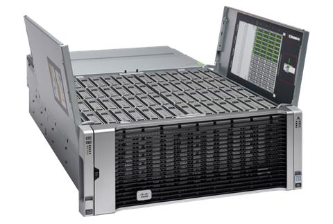
Extending the capability of the Cisco UCS C3000 portfolio, the Cisco UCS S3260 helps you achieve the highest levels of data availability. With dual-node capability that is based on the Intel Xeon scalable processors, it features up to 840 TB of local storage in a compact 4-rack-unit (4RU) form factor. All hard-disk drives can be asymmetrically split between the dual-nodes and are individually hot-swappable. The drives can be built-in in an enterprise-class Redundant Array of Independent Disks (RAID) redundancy or be in a pass-through mode.
This high-density rack server comfortably fits in a standard 32-inch depth rack, such as the Cisco R42610 Rack.
The Cisco UCS S3260 is deployed as a standalone server in both bare-metal or virtualized environments. Its modular architecture reduces TCO by allowing you to upgrade individual components over time and as use cases evolve, without having to replace the entire system.
The Cisco UCS S3260 uses a modular server architecture that, using Cisco’s blade technology expertise, allows you to upgrade the computing or network nodes in the system without the need to migrate data migration from one system to another. It delivers the following:
· Dual server nodes
· Up to 48 computing cores per server node
· Up to 60 drives mixing a large form factor (LFF) with up to 28 solid-state disk (SSD) drives plus 2 SSD SATA boot drives per server node
· Up to 1.5 TB of memory per server node (3 TB Total) with 128GB DIMMs
· Support for 12-Gbps serial-attached SCSI (SAS) drives
· A system I/O Controller either with HBA Passthrough or RAID controller, with DUAL LSI 3316 Chip
· Cisco VIC 1300 Series Embedded Chip supporting Dual port 40Gbps or Cisco VIC 1400 Series supporting up to 100Gbps
· High reliability, availability, and serviceability (RAS) features with tool-free server nodes, system I/O controller, easy-to-use latching lid, and hot-swappable and hot-pluggable components
· Dual 7mm NVMe – Up to 4 TB per node and 25 TB per chassis
· 1G Host Management Port
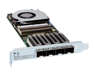
Cisco UCS Virtual Interface Card 1455
The Cisco UCS VIC 1455 is a quad-port Small Form-Factor Pluggable (SFP28) half-height PCIe card designed for the M5 generation of Cisco UCS C-Series Rack Servers. The card supports 10/25-Gbps Ethernet or FCoE. The card can present PCIe standards-compliant interfaces to the host, and these can be dynamically configured as either NICs or HBAs.
Figure 2 Cisco UCS Virtual Interface Card 1455
The Cisco UCS VIC 1400 series provides the following features and benefits:
· Stateless and agile platform: The personality of the card is determined dynamically at boot time using the service profile associated with the server. The number, type (NIC or HBA), identity (MAC address and Worldwide Name [WWN]), failover policy, bandwidth, and Quality-of-Service (QoS) policies of the PCIe interfaces are all determined using the service profile. The capability to define, create, and use interfaces on demand provides a stateless and agile server infrastructure.
· Network interface virtualization: Each PCIe interface created on the VIC is associated with an interface on the Cisco UCS fabric interconnect, providing complete network separation for each virtual cable between a PCIe device on the VIC and the interface on the Fabric Interconnect.
Cisco UCS 6454 Fabric Interconnect
The Cisco UCS 6454 Fabric Interconnect is a core part of the Cisco Unified Computing System, providing both network connectivity and management capabilities for the system (Figure 1). The Cisco UCS 6454 offers line-rate, low-latency, lossless 10/25/40/100 Gigabit Ethernet, Fibre Channel over Ethernet (FCoE), and Fibre Channel functions.
The Cisco UCS 6454 provides the management and communication backbone for the Cisco UCS B-Series Blade Servers, Cisco UCS 5108 B-Series Server Chassis, Cisco UCS Managed C-Series Rack Servers, and Cisco UCS S-Series Storage Servers. All servers attached to the Cisco UCS 6454 Fabric Interconnect become part of a single, highly available management domain. In addition, by supporting a unified fabric, the Cisco UCS 6454 provides both the LAN and SAN connectivity for all servers within its domain.
From a networking perspective, the Cisco UCS 6454 uses a cut-through architecture, supporting deterministic, low-latency, line-rate 10/25/40/100 Gigabit Ethernet ports, switching capacity of 3.82 Tbps, and 160 Gbps bandwidth between FI 6454 and IOM 2208 per 5108 blade chassis, independent of packet size and enabled services. The product family supports Cisco® low-latency, lossless 10/25/40/100 Gigabit Ethernet unified network fabric capabilities, which increase the reliability, efficiency, and scalability of Ethernet networks. The Fabric Interconnect supports multiple traffic classes over a lossless Ethernet fabric from the server through the Fabric Interconnect. Significant TCO savings come from an FCoE optimized server design in which Network Interface Cards (NICs), Host Bus Adapters (HBAs), cables, and switches can be consolidated.
Figure 3 Cisco UCS 6454 Fabric Interconnect
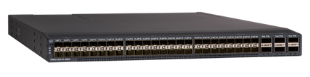
The Cisco UCS 6454 54-Port Fabric Interconnect is a One-Rack-Unit (1RU) 10/25/40/100 Gigabit Ethernet, FCoE and Fibre Channel switch offering up to 3.82 Tbps throughput and up to 54 ports. The switch has 28 10/25-Gbps Ethernet ports, 4 1/10/25-Gbps Ethernet ports, 6 40/100-Gbps Ethernet uplink ports and 16 unified ports that can support 10/25-Gbps Ethernet ports or 8/16/32-Gbps Fibre Channel ports. All Ethernet ports are capable of supporting FCoE.
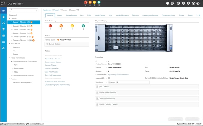
Cisco UCS Manager
Cisco UCS Manager supports the entire Cisco UCS server and Cisco HyperFlex Series hyperconverged infrastructure portfolios. It enables server, fabric, and storage provisioning as well as, device discovery, inventory, configuration, diagnostics, monitoring, fault detection, auditing, and statistics collection. You can extend the benefits of Cisco UCS Manager globally across an enterprise to thousands of servers in multiple domains with Cisco UCS Central Software.
The open platform treats infrastructure as code. It extends the functionality of existing management tools through a broad, mature partner ecosystem. IT organizations can transition to DevOps by evolving existing staff, skills, tools, and processes and making them more efficient, to gain TCO savings.
An open API facilitates integration of Cisco UCS Manager with a wide variety of monitoring, analysis, configuration, deployment, and orchestration tools from other independent software vendors. The API also facilitates customer development through the Cisco UCS PowerTool for PowerShell and a Python SDK.
Figure 4 Cisco UCS Manager
Key Features
· Supports Cisco UCS B-Series Blade and C-Series Rack Servers, the Cisco UCS C3260 storage server, Cisco UCS Mini, and the Cisco HyperFlex hyperconverged infrastructure
· Programmatically controls server, network, and storage resources, with a unified, policy-driven management, so they can be efficiently managed at scale through software
· Works with HTML 5, Java, or CLI graphical user interfaces
· Can automatically detect, inventory, manage, and provision system components that are added or changed
· Facilitates integration with third-party systems management tools
· Builds on existing skills and supports collaboration across disciplines through role-based administration
Cisco Nexus 93180YC-EX
The Cisco Nexus® 9300-EX Series switches belongs to the fixed Cisco Nexus 9000 platform based on Cisco Cloud Scale technology. The platform support cost-effective cloud-scale deployments, an increased number of endpoints, and cloud services. The platform is built on modern system architecture designed to provide high performance and meet the evolving needs of highly scalable data centers and growing enterprises.
Cisco Nexus 9300-EX series switches offer a variety of interface options to transparently migrate existing data centers from 100-Mbps, 1-Gbps, and 10-Gbps speeds to 25-Gbps at the server, and from 10- and 40-Gbps speeds to 50- and 100-Gbps at the aggregation layer. The platforms provide investment protection for customers, delivering large buffers, highly flexible Layer 2 and Layer 3 scalability, and performance to meet the changing needs of virtualized data centers and automated cloud environments.
Cisco provides two modes of operation for Cisco Nexus 9000 Series Switches. Organizations can use Cisco NX-OS Software to deploy the switches in standard Cisco Nexus switch environments (NX-OS mode). Organizations can also deploy the infrastructure that is ready to support the Cisco Application Centric Infrastructure (Cisco ACI™) platform to take full advantage of an automated, policy-based, systems-management approach (ACI mode).
The Cisco Nexus 93180YC-EX Switch is a 1-Rack-Unit (1RU) switch with latency of less than 1 microsecond that supports 3.6 Terabits per second (Tbps) of bandwidth and over 2.6 billion packets per second (bpps). The 48 downlink ports on the 93180YC-EX can be configured to work as 1-, 10-, or 25-Gbps ports, offering deployment flexibility and investment protection. The uplink can support up to six 40- and 100-Gbps ports, or a combination of 1-, 10-, 25-, 40-, 50, and 100-Gbps connectivity, offering flexible migration options. The switch has FC-FEC enabled for 25Gbps and supports up to 3m in DAC connectivity. Please check Cisco Optics Matrix for the most updated support.
Figure 5 Cisco Nexus 93180 YC-EX
IBM Cloud Object Storage
The IBM COS System platform is ideal whenever enterprises need to securely store large volumes of unstructured data with high availability and where latency is not a primary consideration.
With the unprecedented growth in new digital information, use cases have emerged that enable organizations to store and distribute limitless data. A distributed and decentralized storage architecture along with an Object Storage interface enables enterprises to deliver data to their users across the globe as never before. The use cases covered in this Cisco Validated Design include:
· Content Repository
· Storage-as-a-service
· Enterprise Collaboration
· Backup
· Archive
The IBM COS System software platform uses an approach for cost-effectively storing large volumes of unstructured data while still ensuring security, availability, and reliability.
The IBM COS System storage technology uses Information Dispersal Algorithms (IDA) to separate data into unrecognizable “slices” that are distributed via network connections to storage nodes locally or across the world. The collection of dispersed storage appliances creates what is called a dispersed storage network. With dispersed storage technology, transmission and storage of data are inherently private and secure. No complete copy of the data exists in any single storage node. Only a subset of nodes needs to be available to fully retrieve the data on the network.
IDA technology transforms data into slices by using equations such that a subset of the slices can be used to re-create the original data. These slices, which are like packets but are for data storage, are then stored across multiple storage appliances (or storage nodes). Slices are created by using a combination of erasure coding, encryption, and sophisticated dispersal algorithms.
Dispersed storage systems are well-suited for storing unstructured data like digital media of all types, documents that are produced by desktop productivity applications, and server log files, which are typically larger files. Dispersal is not optimized for transaction-oriented primary storage for databases and similar high IOP workloads because of the extra processing associated with slicing and dispersing.
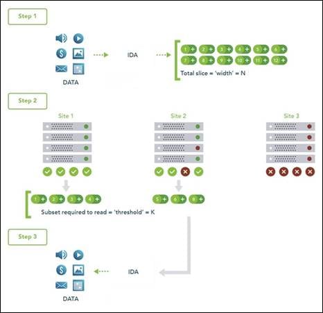
At a basic level, the IBM COS System platform uses three steps for slicing, dispersing, and retrieving data (Figure 6):
1. Data is virtualized, transformed, sliced, and dispersed by using IDAs. In the first figure, the data is separated into 12 slices. So the "width" (n) of the system is 12.
2. Slices are distributed to some combination of separate disks, storage nodes, and geographic locations. In this example, the slices are distributed to three different sites.
3. The data is retrieved from a subset of slices. In this example, the number of slices that are needed to retrieve the data is 8. So the "threshold" (k) of the system is 8.
Given a width of 12 and a threshold of 8, you can refer to this example as a "8 of 12" (k of n) configuration.
The configuration of a system is determined by the level of reliability needed. In a "8 of 12" configuration, four slices can be lost or unavailable and the data can still be retrieved because the threshold of seven slices is met. With a "5 of 8" configuration, only three slices can be lost, so the level of reliability is lower. Conversely, with a "20 of 32" configuration, 12 slices can be lost, so the level of reliability is higher.
Figure 6 How Dispersed Storage Works
Multi-site failure
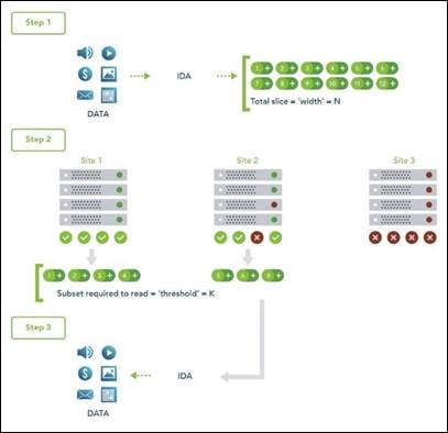
With dispersed storage, only a subset of slices is needed to retrieve the data. A dispersed storage system can tolerate appliance failures both within a single site and across multiple sites, as shown in Figure 7.
1. Data is virtualized, transformed, sliced, and dispersed by using Information Dispersal Algorithm (IDAs). The "width" (n) of the system in this example is 12.
2. Slices are distributed to separate disks, storage nodes, and geographic locations. In this example, the slices are distributed to four geographically dispersed sites.
3. The data is retrieved from a subset of slices. In this example, the number of slices that are needed to retrieve the data is 8. So even though failures are occurring across all three sites, the data is still available to be retrieved because the "threshold" of seven available slices is reached.
Figure 7 Multi-Site Management

Single-site, multiple-device failure
A dispersed storage system can also be deployed in a single site with the ability to tolerate the failure of multiple appliances within that site, as shown in Figure 8.
1. Data is virtualized, transformed, sliced, and dispersed by using IDAs. The "width" (n) of the system in this example is 12.
2. Slices are distributed to separate disks, storage nodes, and geographic locations. In this example, the slices are distributed to four different racks within a single site.
3. The data is retrieved from a subset of slices. In this example, the number of slices that are needed to retrieve the data is 7. So even though each rack experienced one or more device failures, the data can be retrieved because the "threshold" of seven slices is met. Even with five slices unavailable, the data can be bit-perfectly re-created.
Figure 8 Single/Multi-Site failure management
Cloud Object Storage Components
You can use the IBM COS System platform to create storage systems that have three software components: the IBM COS Manager software, IBM COS Accesser software and IBM COS Slicestor software.
The software components can be deployed on a wide range of compatible industry-standard hardware platforms, as virtual machines, and in the case of the IBM COS Accesser software, as a software application that is running on a Linux operating system. Physical and virtual deployment can be combined in a single system by using virtual machine deployment for the IBM COS Manager and IBM COS Accesser software and physical servers for the IBM COS Slicestor software as an example.
Each of the three software components serves a specific function:
· The IBM COS Manager software is responsible for monitoring the health and performance of the system, configuring the system and provisioning storage, managing faults, and other administrative and operational functions.
· The IBM COS Accesser software is responsible for encrypting/encoding data on ingest and decoding/decrypting it when read and managing the dispersal of slices of data resulting from this process across a set of IBM COS Slicestor nodes.
· The IBM COS Slicestor software is responsible for the storage of slices.
The underlying storage pool of a dispersed or concentrated dispersed storage system can be shared and is jointly accessible by multiple access protocols.
When the IBM Cloud Object Storage Manager software, IBM Cloud Object Storage Accesser software, and IBM Cloud Object Storage Slicestor software are deployed on a hardware platform that is certified by IBM®, the following benefits result:
· Minimum time to production on initial deployment because hardware and software compatibility and configuration are predefined and validated by IBM.
· Hardware configuration optimized to maximize value of the IBM Cloud Object Storage System.
· Increased system reliability due to low-level monitoring and management of hardware component health.
· Access to IBM support staff that are familiar with both the hardware and software components of the system.
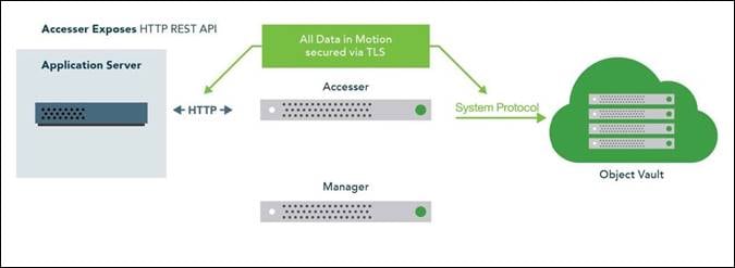
Object-based Access Methods
The Simple Object interface is accessed with a HTTP/REST API. Simple PUT, GET, DELETE, and LIST commands allow applications to access digital content, and the resulting object ID is stored directly within the application.
REST API Access to Storage
Figure 9 REST API Storage Interfaces
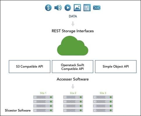
REST is a style of software architecture for distributed hypermedia information retrieval systems such as the World Wide Web. REST-style architectures consist of clients and servers. Clients initiate requests to servers. Servers process requests and return associated responses. Requests and responses are built around the transfer of various representations of the resources.
The REST API works in way that is similar to retrieving a Universal Resource Locator (URL). But instead of requesting a webpage, the application is referencing an object.
REST API access to storage offers several advantages:
· Tolerates internet latency
· Provides for "programmable" storage
· Provides efficient global access to large amounts of data
Data Security
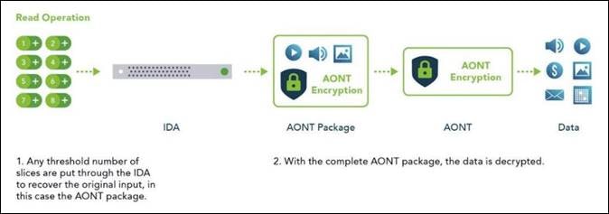
SecureSlice is the technology that is used to guarantee confidentiality, integrity, and availability of data stored on the system. SecureSlice combines two algorithms: an Information Dispersal Algorithm (IDA) and an All-or-Nothing Transform (AONT). AONT is a mode of encryption in which the information can be deciphered only if all the information is known. The diagrams illustrate basic write and read operations by using SecureSlice.
Figure 10 Write Operation
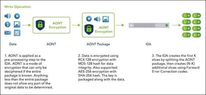
Figure 11 Read Operation
Network Security
All network traffic that is flowing into or out of appliances in a dispersed storage system is encrypted by using TLS with AES. Storage nodes can be placed anywhere without complex firewall or VPN setup, as shown in Figure 12.
Availability Features
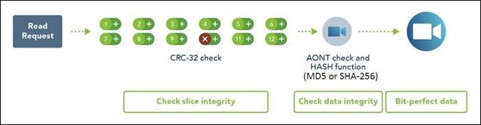
The availability features of a dispersed storage system provide continuous error detection and correction, ensuring bit-perfect data availability.
Integrity Check on All Slices and Files
A dispersed storage system checks for data integrity through an intelligent background process that proactively scans and corrects errors. It scans data slices for integrity, rebuilds any corrupted slices, and checks for both slice integrity and file data integrity before delivery. This process guarantees bit-perfect data delivery through proactive correction of bit errors and correction of latent soft errors that might occur during normal read/write operations. It also ensures that data cannot be modified without authorization and that malicious threats are detected.
Figure 13 Integrity Checks
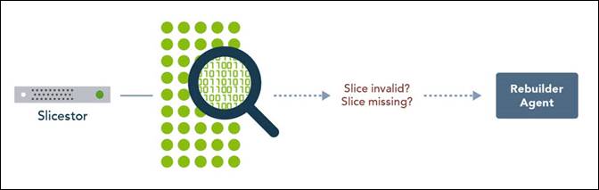
Continuous Error Correction
If a slice is determined to be corrupted, meaning that the integrity check value is invalid, the IBM Cloud Object Storage Slicestor appliance starts the distributed rebuilder technology to replace the slice with a valid slice. If the slice is missing, the distributed rebuilder technology re-creates a valid slice. Continuous error correction increases system availability because it is not waiting for data to be read to detect errors. It is crucial with long-term archives and massive digital stores where information isn’t as frequently read. The distributed rebuilder model allows for predictability because the rebuilder is "always on" at a moderated rate, making I/O performance much more predictable, and scalable, as the rebuilder grows with storage.
Figure 14 Continuous Error Correction
Embedded Accesser
This CVD uses an Embedded Accesser Appliance function. The Embedded Accesser Appliance feature provides Accesser Appliance functions on the IBM COS Slicestor Appliance. This feature provides customers an opportunity to save on capital expenses by using one physical appliance for both Accesser and Slicestor appliance functions. However, before you deploy this feature, careful consideration needs to be given to the Slicestor hardware and the workload presented to the servers and the load balancing between the available Slicestor appliances.
· Spread the load on all the available Embedded Accesser® Appliance.
· The performance degradation with Index ON cases might be more pronounced with Embedded Accesser® Appliance.
· There is some degree of performance degradation on all workloads with Embedded Accesser® Appliance.
· Workloads such as small file writes are more severely impacted than the others.
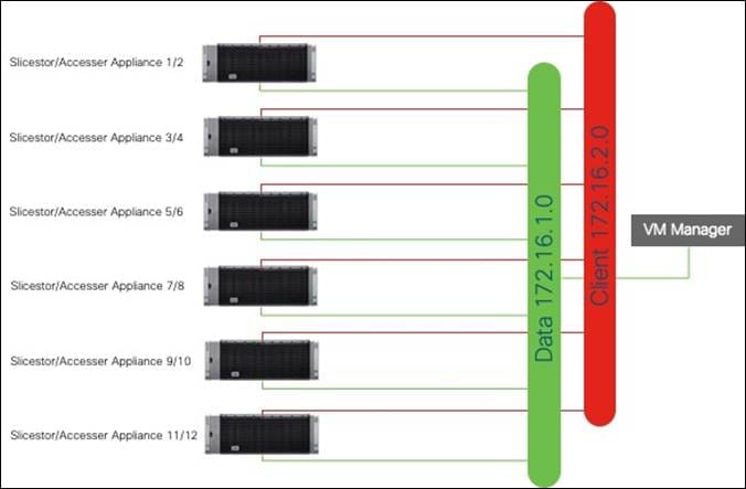
Network
Network administrators can configure the first four layers of the OSI model on a system to use separate network traffic between storage data, management information, and client data.
An IBM COS System that uses certified devices, can dedicate network interfaces (NICs) to three distinct networks to transfer:
· Data within the system
· Management information to management systems
· Data to a client application
These networks are referred to as Channels.
Figure 15 How Multiple Networks Work at a High-Level
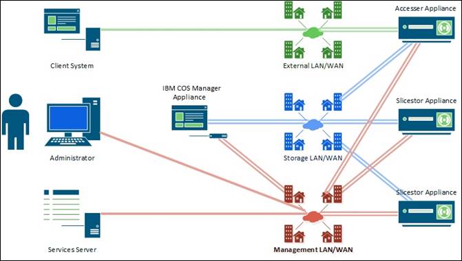
In separating data into channels, the system provides better security, more flexible management options and minimizes network congestion for high-performance applications.
Solution Overview
This Cisco Validated Design provides a comprehensive, end-to-end guide for deploying IBM COS with Embedded Accesser on Cisco UCS S3260 within infrastructure made possible by Cisco UCS Manager and the Cisco UCS 6454 Fabric Interconnects.
One of the key design goals of this scale out architecture was to deploy all elements on 25GbE networking end to end within a single Cisco UCS domain. Both IBM COS components – Embedded Accesser, and Slicestor – utilize the robust throughput and low latency only provided by the Cisco UCS 6454 Fabric Interconnect. Additionally, both components take advantage of the flexibility provided by the stateless nature of Cisco UCS service profiles and service profile templates.
This design uses the Cisco Nexus 9000 series data center switches in NX-OS standalone mode but provides investment protection to migrate to ACI or higher network bandwidths (1/10/25/40/50/100Gbps) while enabling innovative analytics and visibility using Tetration and automation that support in-box and off-box Python scripting and Open NX-OS that support dev-ops tools (Chef, Puppet, Ansible).
The key design for IBM COS on Cisco UCS S3260 is shown in Figure 16.
Figure 16 Topology of IBM COS on Cisco UCS S3260 M5

· Manager instance deployed as virtual machine OVA
· Embedded Accesser deployed on Slicestor
· Slicestor deployed on Cisco UCS S3260
· Cisco UCS S3260 connected to UCS 6454 Fabric Interconnect with 25Gbps line speed
· Cisco UCS 6454 Fabric Interconnect connected to Nexus 93180YC-EX with 25Gbps line speed
IBM Cloud Object Configuration for Cisco Validated Design
The current Design and Deployment Guide uses the following configuration for IBM COS:
· Virtual Manager using an OVA
· Embedded Accesser
· Standard Dispersal Mode (SD) with IDA 12/8/10
Details for the specific SD Mode are listed in Table 2.
Table 2 Configuration for SD Mode used in this Design and Deployment Guide
| Sites |
IDA |
Store Count |
Disks per Store |
Disk Size |
Raw Capacity |
Usable Capacity |
Expansion Factor |
| 1 |
12/8/10 |
12 |
28 |
10 TB |
3360 TB |
2240 TB |
1.50 |
General Hardware Requirements
| Component |
Model |
Quantity |
Comments |
| IBM Slicestor/Embedded Accesser |
Cisco UCS S3260 M5 |
6 chassis / 12 nodes |
Per server node: · 2 x Intel Cascade Lake 4214 · 384 GB Memory · 1 x VIC 1455 · 12 Gbit SAS RAID Controller · Disks o 2 x SSD/HDD RAID 1 – Boot o 28 x NL-SAS HDD JBOD – Data |
| IBM Manager |
Virtual Machine OVA[1] |
1 |
· 4 vCPU · 64 GB Memory · 128 GB Disk · 1 x Network |
| Cisco UCS Fabric Interconnects |
Cisco UCS 6454 Fabric Interconnects |
2 |
|
| Switches |
Cisco Nexus 93180YC-EX |
2 |
|
Compute Layer Design
Each Cisco UCS S3260 server is equipped with a Cisco UCS Virtual Interface Card (VIC) supporting quad 25-Gbps fabric connectivity. Only two ports out of four are used to fulfill the network requirements in this solution. The Cisco UCS VICs eliminate the need for separate physical interface cards on each server for data and client connectivity. For this solution with IBM COS ClevOS the VIC is configured with five virtual NICs. There is one vNIC configured for the Inband management of UCSM. Two vNICs are configured for data network, connected to different Fabric Interconnects and two vNICs are configured for client network, connected to different Fabric Interconnects as well. IBM COS is configured to leverage the two vNICs for data and client network to provide operational active-backup redundancy in software.
Cisco UCS Server Connectivity to Unified Fabric
Cisco UCS servers are typically deployed with a single VIC card for unified network and storage access. The Cisco VIC connects into a redundant unified fabric provided by a pair of Cisco UCS Fabric Interconnects. Fabric Interconnects are an integral part of Cisco Unified Computing System, providing unified management and connectivity to all attached blades, chassis and rack servers. Fabric Interconnects provide a lossless and deterministic FCoE fabric. For the servers connected to it, the Fabric Interconnects provide LAN, SAN and management connectivity to the rest of the network.
Validated Compute Design
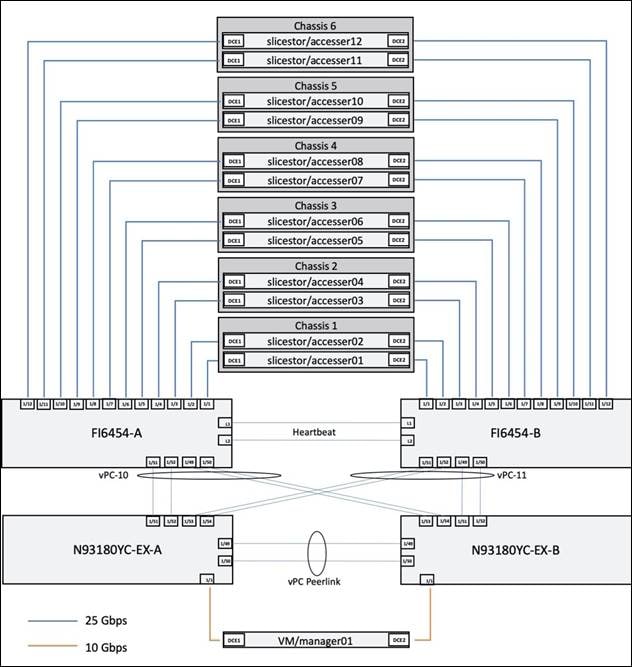
The connectivity of the solution is based on 25 Gbps. All components are connected together via 25 Gbps SFP+ cables except the virtual Manager node, which uses a 10 Gbit connectivity. Between both Cisco Nexus 93180YC-EX switches are 2 x 40 Gbit cabling. Each Cisco UCS 6454 Fabric Interconnect is connected via 2 x 40 Gbps to each Cisco UCS 93180YC-EX switch. And each Cisco UCS S3260 M5 server is connected with a single 25 Gbit cable to each Fabric Interconnect.
The exact cabling for the IBM COS solution is illustrated in following picture. It shows also the vNIC configuration for the Data, Client and Management channel.
The virtual IBM COS Management node is connected to both Nexus 93180YC-EX and has access to the Slicestors/Accessers.
Figure 17 IBM COS Cabling Diagram
For a better reading and overview, the exact physical connectivity between the Cisco UCS 6454 Fabric Interconnects and the Cisco UCS S-Series server is listed in Table 4.
Table 4 Physical Connectivity between FI6454 and Cisco S3260 M5
| Port |
Role |
FI6454-A |
FI6454-B |
| Eth1/1 |
Server |
slicestor/accesser01, DCE1 |
slicestor/accesser01, DCE2 |
| Eth1/2 |
Server |
slicestor/accesser02, DCE1 |
slicestor/accesser02, DCE2 |
| Eth1/3 |
Server |
slicestor/accesser03, DCE1 |
slicestor/accesser03, DCE2 |
| Eth1/4 |
Server |
slicestor/accesser04, DCE1 |
slicestor/accesser04, DCE2 |
| Eth1/5 |
Server |
slicestor/accesser05, DCE1 |
slicestor/accesser05, DCE2 |
| Eth1/6 |
Server |
slicestor/accesser06, DCE1 |
slicestor/accesser06, DCE2 |
| Eth1/7 |
Server |
slicestor/accesser07, DCE1 |
slicestor/accesser07, DCE2 |
| Eth1/8 |
Server |
slicestor/accesser08, DCE1 |
slicestor/accesser08, DCE2 |
| Eth1/9 |
Server |
slicestor/accesser09, DCE1 |
slicestor/accesser09, DCE2 |
| Eth1/10 |
Server |
slicestor/accesser10, DCE1 |
slicestor/accesser10, DCE2 |
| Eth1/11 |
Server |
slicestor/accesser11, DCE1 |
slicestor/accesser11, DCE2 |
| Eth1/12 |
Server |
slicestor/accesser12, DCE1 |
slicestor/accesser12, DCE2 |
| Eth1/49 |
Network |
N93180YC-EX-B, Eth1/53 |
N93180YC-EX-B, Eth1/51 |
| Eth1/50 |
Network |
N93180YC-EX-B, Eth1/54 |
N93180YC-EX-B, Eth1/52 |
| Eth1/51 |
Network |
N93180YC-EX-A, Eth1/51 |
N93180YC-EX-A, Eth1/53 |
| Eth1/52 |
Network |
N93180YC-EX-A, Eth1/52 |
N93180YC-EX-A, Eth1/54 |
High Availability
The Cisco and IBM solution was designed for maximum availability of the complete infrastructure (compute, network, storage) with no single points of failure.
Compute
· Cisco UCS provides redundancy at the component and link level and end-to-end path redundancy to the LAN network.
· Cisco UCS S3260 M5 Chassis is highly redundant with redundant power supplies and fans.
· Each server is deployed using vNICs that provide redundant connectivity to the unified fabric. NIC failover is enabled between Cisco UCS Fabric Interconnects using Cisco UCS Manager. This is done for all Slicestor with Embedded Accesser node vNICs.
Network
· Link aggregation using port channels and virtual port channels can be used throughout the design for higher bandwidth and availability, if the optional Cisco UCS Nexus 93180YC-EX is deployed. Between each Cisco UCS 6454 Fabric Interconnect and both Cisco Nexus 93180YC-EX is one virtual Port Channel (vPC) configured. vPCs allow links that are physically connected to two different Cisco Nexus 9000 switches to appear to the Fabric Interconnect as coming from a single device and as part of a single port channel.
· Each Slicestor with Embedded Accesser is configured in mode 1 active-backup bonding mode at the ClevOS software layer for data and client network.
Figure 18 illustrates the logical configuration of the network for the IBM COS solution with embedded Accesser and SD mode. Data and Client network are on different vNICs and subnets. This makes sure that the traffic is separated.
Figure 18 Logical View of the Network Configuration used in this CVD
Jumbo Frames
This design recommends end-to-end jumbo frames with an MTU of 9000 Bytes across the LAN and Unified Fabric links. Jumbo frames increase the throughput between devices by enabling larger sized frames to be sent and received on the wire while reducing the CPU resources necessary to process them. Jumbo frames were enabled during validation on the LAN network links in the Cisco Nexus switching layer and on the Unified Fabric links for the Data and Client network.
Software Distributions and Versions
The required software distribution versions are listed below in Table 5.
| Layer |
Component |
Version or Release |
| Cisco UCS S3260 Chassis |
Board Controller |
1.0.21 |
| Chassis Management Controller |
4.1(1f) |
|
| Shared Adapter |
5.1(1f) |
|
| SAS Expander 1/2 |
04.08.01.B083 |
|
| Cisco UCS S3260 M5 Server |
BIOS |
S3X60M5.4.1.1c |
| CIMC Controller |
4.1(1f) |
|
| Storage Controller SAS 1/2 |
29.00.1-0358 |
|
| Disk Firmware |
A3Z4 |
|
| Network 6454 Fabric Interconnect |
Cisco UCS Manager |
4.1(1c) |
| Kernel |
7.0(3)N2(4.11b) |
|
| System |
7.0(3)N2(4.11b) |
|
| Network Nexus 93180YC-EX |
BIOS |
07.65 |
| NXOS |
9.2(2) |
|
| Software |
IBM COS |
3.14.11.39 |
![]() We strongly recommend upgrading the Nexus software to the latest version 9.3(2) because of Cisco NX-OS Software Cisco Discovery Protocol Remote Code Execution Vulnerability. More information can be found here: https://tools.cisco.com/security/center/content/CiscoSecurityAdvisory/cisco-sa-20200205-nxos-cdp-rce#fs
We strongly recommend upgrading the Nexus software to the latest version 9.3(2) because of Cisco NX-OS Software Cisco Discovery Protocol Remote Code Execution Vulnerability. More information can be found here: https://tools.cisco.com/security/center/content/CiscoSecurityAdvisory/cisco-sa-20200205-nxos-cdp-rce#fs
Fabric Configuration
This section provides the details to configure a fully redundant, highly available Cisco UCS 6454 fabric configuration.
· Initial setup of Cisco Nexus 93180YC-EX Switch A and B
· Initial setup of the Cisco UCS Fabric Interconnect 6454 A and B
· Connect to Cisco UCS Manager using virtual IP address of the web browser
· Launch Cisco UCS Manager
· Enable server and uplink ports
· Start discovery process
· Create pools and policies for service profile template
· Create storage profiles
· Create Service Profile templates and appropriate Service Profiles
· Associate Service Profiles to servers
Configure Cisco Nexus 93180YC-EX Switch A and B
Both Cisco UCS Fabric Interconnect A and B are connected to two Cisco Nexus 93180YC-EX switches for connectivity to applications and clients. The following sections describe the setup of both Cisco Nexus 93180YC-EX switches.
Initial Setup of Cisco Nexus 93180YC-EX Switch A and B
To configure Switch A, connect a Console to the Console port of each switch, power on the switch and follow these steps:
1. Type yes.
2. Type n.
3. Type n.
4. Type n.
5. Enter the switch name.
6. Type y.
7. Type your IPv4 management address for Switch A.
8. Type your IPv4 management netmask for Switch A.
9. Type y.
10. Type your IPv4 management default gateway address for Switch A.
11. Type n.
12. Type n.
13. Type y for ssh service.
14. Press <Return> and then <Return>.
15. Type y for ntp server.
16. Type the IPv4 address of the NTP server.
17. Type in L2 for interface layer.
18. Press <Return> and again <Return>.
19. Check the configuration and if correct then press <Return> and again <Return>.
The complete setup looks like the following:
---- System Admin Account Setup ----
Do you want to enforce secure password standard (yes/no) [y]:
Enter the password for "admin":
Confirm the password for "admin":
---- Basic System Configuration Dialog VDC: 1 ----
This setup utility will guide you through the basic configuration of
the system. Setup configures only enough connectivity for management
of the system.
Please register Cisco Nexus9000 Family devices promptly with your
supplier. Failure to register may affect response times for initial
service calls. Nexus9000 devices must be registered to receive
entitled support services.
Press Enter at anytime to skip a dialog. Use ctrl-c at anytime
to skip the remaining dialogs.
Would you like to enter the basic configuration dialog (yes/no): yes
Create another login account (yes/no) [n]:
Configure read-only SNMP community string (yes/no) [n]:
Configure read-write SNMP community string (yes/no) [n]:
Enter the switch name : SJC02DMZ-G14-N93180YC-EX-A
Continue with Out-of-band (mgmt0) management configuration? (yes/no) [y]:
Mgmt0 IPv4 address : 172.16.0.4
Mgmt0 IPv4 netmask : 255.255.255.0
Configure the default gateway? (yes/no) [y]:
IPv4 address of the default gateway : 192.168.11.3
Configure advanced IP options? (yes/no) [n]:
Enable the telnet service? (yes/no) [n]:
Enable the ssh service? (yes/no) [y]:
Type of ssh key you would like to generate (dsa/rsa) [rsa]:
Number of rsa key bits <1024-2048> [1024]:
Configure the ntp server? (yes/no) [n]: y
NTP server IPv4 address : 173.38.201.115
Configure default interface layer (L3/L2) [L3]: L2
Configure default switchport interface state (shut/noshut) [shut]:
Configure CoPP system profile (strict/moderate/lenient/dense) [strict]:
The following configuration will be applied:
password strength-check
switchname SJC02DMZ-G14-N93180YC-EX-A
vrf context management
ip route 0.0.0.0/0 192.168.11.3
exit
no feature telnet
ssh key rsa 1024 force
feature ssh
ntp server 173.38.201.115
no system default switchport
system default switchport shutdown
copp profile strict
interface mgmt0
ip address 172.16.0.4 255.255.255.0
no shutdown
Would you like to edit the configuration? (yes/no) [n]:
Use this configuration and save it? (yes/no) [y]:
[########################################] 100%
Copy complete.
User Access Verification
SJC02DMZ-G14-N93180YC-EX-A login:
![]() Repeat the same steps for the Cisco Nexus 93180YC-EX Switch B with the exception of configuring a different IPv4 management address in step 7.
Repeat the same steps for the Cisco Nexus 93180YC-EX Switch B with the exception of configuring a different IPv4 management address in step 7.
Enable Features on Cisco Nexus 93180YC-EX Switch A and B
To enable the features UDLD, VLAN, LACP, HSRP, VPC, and Jumbo Frames, connect to the management interface via ssh on both switches and follow these steps on both Switch A and B:
Switch A
SJC02DMZ-G14-N93180YC-EX-A # configure terminal
Enter configuration commands, one per line. End with CNTL/Z.
SJC02DMZ-G14-N93180YC-EX-A (config)# feature udld
SJC02DMZ-G14-N93180YC-EX-A (config)# feature interface-vlan
SJC02DMZ-G14-N93180YC-EX-A(config)# feature lacp
SJC02DMZ-G14-N93180YC-EX-A(config)# feature vpc
SJC02DMZ-G14-N93180YC-EX-A(config)# feature hsrp
SJC02DMZ-G14-N93180YC-EX-A(config)# system jumbomtu 9216
SJC02DMZ-G14-N93180YC-EX-A(config)# spanning-tree port type edge bpduguard default
SJC02DMZ-G14-N93180YC-EX-A(config)# spanning-tree port type edge bpdufilter default
SJC02DMZ-G14-N93180YC-EX-A(config)# port-channel load-balance src-dst ip-l4port-vlan
SJC02DMZ-G14-N93180YC-EX-A(config)# exit
SJC02DMZ-G14-N93180YC-EX-A#
Switch B
SJC02DMZ-G14-N93180YC-EX-B# configure terminal
Enter configuration commands, one per line. End with CNTL/Z.
SJC02DMZ-G14-N93180YC-EX-B(config)# feature udld
SJC02DMZ-G14-N93180YC-EX-B(config)# feature interface-vlan
SJC02DMZ-G14-N93180YC-EX-B(config)# feature lacp
SJC02DMZ-G14-N93180YC-EX-B(config)# feature vpc
SJC02DMZ-G14-N93180YC-EX-A(config)# feature hsrp
SJC02DMZ-G14-N93180YC-EX-B(config)# system jumbomtu 9216
SJC02DMZ-G14-N93180YC-EX-B(config)# spanning-tree port type edge bpduguard default
SJC02DMZ-G14-N93180YC-EX-B(config)# spanning-tree port type edge bpdufilter default
SJC02DMZ-G14-N93180YC-EX-B(config)# port-channel load-balance src-dst ip-l4port-vlan
SJC02DMZ-G14-N93180YC-EX-B(config)# exit
SJC02DMZ-G14-N93180YC-EX-B#
Configuring VLANs on Nexus 93180YC-EX Switch A and B
To configure VLAN Native-VLAN and Public-VLAN, follow these steps on Switch A and Switch B:
Switch A
SJC02DMZ-G14-N93180YC-EX-A# config terminal
Enter configuration commands, one per line. End with CNTL/Z.
SJC02DMZ-G14-N93180YC-EX-A(config)# vlan 100
SJC02DMZ-G14-N93180YC-EX-A(config-vlan)# name Management
SJC02DMZ-G14-N93180YC-EX-A(config-vlan)# exit
SJC02DMZ-G14-N93180YC-EX-A(config)# vlan 101
SJC02DMZ-G14-N93180YC-EX-A(config-vlan)# name Data
SJC02DMZ-G14-N93180YC-EX-A(config-vlan)# exit
SJC02DMZ-G14-N93180YC-EX-A(config)# vlan 102
SJC02DMZ-G14-N93180YC-EX-A(config-vlan)# name Client
SJC02DMZ-G14-N93180YC-EX-A(config-vlan)# exit
SJC02DMZ-G14-N93180YC-EX-A(config)#interface vlan 100
SJC02DMZ-G14-N93180YC-EX-A(config-if)# no shut
SJC02DMZ-G14-N93180YC-EX-A(config-if)# mtu 9216
SJC02DMZ-G14-N93180YC-EX-A(config-if)# no ip redirects
SJC02DMZ-G14-N93180YC-EX-A(config-if)# ip address 172.16.0.2/24
SJC02DMZ-G14-N93180YC-EX-A(config-if)# no ipv6 redirects
SJC02DMZ-G14-N93180YC-EX-A(config-if)# hsrp version 2
SJC02DMZ-G14-N93180YC-EX-A(config-if)# hsrp 101
SJC02DMZ-G14-N93180YC-EX-A(config-if-hsrp)# preempt delay minimum 300
SJC02DMZ-G14-N93180YC-EX-A(config-if-hsrp)# priority 110
SJC02DMZ-G14-N93180YC-EX-A(config-if-hsrp)# ip 172.16.0.1
SJC02DMZ-G14-N93180YC-EX-A(config-if-hsrp)# exit
SJC02DMZ-G14-N93180YC-EX-A(config-if)# exit
SJC02DMZ-G14-N93180YC-EX-A(config)#interface vlan 101
SJC02DMZ-G14-N93180YC-EX-A(config-if)# no shut
SJC02DMZ-G14-N93180YC-EX-A(config-if)# mtu 9216
SJC02DMZ-G14-N93180YC-EX-A(config-if)# no ip redirects
SJC02DMZ-G14-N93180YC-EX-A(config-if)# ip address 172.16.1.2/24
SJC02DMZ-G14-N93180YC-EX-A(config-if)# no ipv6 redirects
SJC02DMZ-G14-N93180YC-EX-A(config-if)# hsrp version 2
SJC02DMZ-G14-N93180YC-EX-A(config-if)# hsrp 101
SJC02DMZ-G14-N93180YC-EX-A(config-if-hsrp)# preempt delay minimum 300
SJC02DMZ-G14-N93180YC-EX-A(config-if-hsrp)# priority 110
SJC02DMZ-G14-N93180YC-EX-A(config-if-hsrp)# ip 172.16.1.1
SJC02DMZ-G14-N93180YC-EX-A(config-if-hsrp)# exit
SJC02DMZ-G14-N93180YC-EX-A(config-if)# exit
SJC02DMZ-G14-N93180YC-EX-A(config)#interface vlan 102
SJC02DMZ-G14-N93180YC-EX-A(config-if)# no shut
SJC02DMZ-G14-N93180YC-EX-A(config-if)# mtu 9216
SJC02DMZ-G14-N93180YC-EX-A(config-if)# no ip redirects
SJC02DMZ-G14-N93180YC-EX-A(config-if)# ip address 172.16.2.2/24
SJC02DMZ-G14-N93180YC-EX-A(config-if)# no ipv6 redirects
SJC02DMZ-G14-N93180YC-EX-A(config-if)# hsrp version 2
SJC02DMZ-G14-N93180YC-EX-A(config-if)# hsrp 102
SJC02DMZ-G14-N93180YC-EX-A(config-if-hsrp)# preempt delay minimum 300
SJC02DMZ-G14-N93180YC-EX-A(config-if-hsrp)# priority 110
SJC02DMZ-G14-N93180YC-EX-A(config-if-hsrp)# ip 172.16.2.1
SJC02DMZ-G14-N93180YC-EX-A(config-if-hsrp)# exit
SJC02DMZ-G14-N93180YC-EX-A(config-if)# exit
SJC02DMZ-G14-N93180YC-EX-A(config)# copy run start
Switch B
SJC02DMZ-G14-N93180YC-EX-B# config terminal
Enter configuration commands, one per line. End with CNTL/Z.
SJC02DMZ-G14-N93180YC-EX-B(config)# vlan 100
SJC02DMZ-G14-N93180YC-EX-B(config-vlan)# name Management
SJC02DMZ-G14-N93180YC-EX-B(config-vlan)# exit
SJC02DMZ-G14-N93180YC-EX-B(config)# vlan 101
SJC02DMZ-G14-N93180YC-EX-B(config-vlan)# name Data
SJC02DMZ-G14-N93180YC-EX-B(config-vlan)# exit
SJC02DMZ-G14-N93180YC-EX-B(config)# vlan 102
SJC02DMZ-G14-N93180YC-EX-B(config-vlan)# name Client
SJC02DMZ-G14-N93180YC-EX-B(config-vlan)# exit
SJC02DMZ-G14-N93180YC-EX-B(config)#interface vlan 100
SJC02DMZ-G14-N93180YC-EX-B(config-if)# no shut
SJC02DMZ-G14-N93180YC-EX-B(config-if)# mtu 9216
SJC02DMZ-G14-N93180YC-EX-B(config-if)# no ip redirects
SJC02DMZ-G14-N93180YC-EX-B(config-if)# ip address 172.16.0.3/24
SJC02DMZ-G14-N93180YC-EX-B(config-if)# no ipv6 redirects
SJC02DMZ-G14-N93180YC-EX-B(config-if)# hsrp version 2
SJC02DMZ-G14-N93180YC-EX-B(config-if)# hsrp 101
SJC02DMZ-G14-N93180YC-EX-B(config-if-hsrp)# preempt delay minimum 300
SJC02DMZ-G14-N93180YC-EX-B(config-if-hsrp)# priority 120
SJC02DMZ-G14-N93180YC-EX-B(config-if-hsrp)# ip 172.16.0.1
SJC02DMZ-G14-N93180YC-EX-B(config-if-hsrp)# exit
SJC02DMZ-G14-N93180YC-EX-B(config-if)# exit
SJC02DMZ-G14-N93180YC-EX-B(config)#interface vlan 101
SJC02DMZ-G14-N93180YC-EX-B(config-if)# no shut
SJC02DMZ-G14-N93180YC-EX-B(config-if)# mtu 9216
SJC02DMZ-G14-N93180YC-EX-B(config-if)# no ip redirects
SJC02DMZ-G14-N93180YC-EX-B(config-if)# ip address 172.16.1.3/24
SJC02DMZ-G14-N93180YC-EX-B(config-if)# no ipv6 redirects
SJC02DMZ-G14-N93180YC-EX-B(config-if)# hsrp version 2
SJC02DMZ-G14-N93180YC-EX-B(config-if)# hsrp 101
SJC02DMZ-G14-N93180YC-EX-B(config-if-hsrp)# preempt delay minimum 300
SJC02DMZ-G14-N93180YC-EX-B(config-if-hsrp)# priority 120
SJC02DMZ-G14-N93180YC-EX-B(config-if-hsrp)# ip 172.16.1.1
SJC02DMZ-G14-N93180YC-EX-B(config-if-hsrp)# exit
SJC02DMZ-G14-N93180YC-EX-B(config-if)# exit
SJC02DMZ-G14-N93180YC-EX-B(config)#interface vlan 102
SJC02DMZ-G14-N93180YC-EX-B(config-if)# no shut
SJC02DMZ-G14-N93180YC-EX-B(config-if)# mtu 9216
SJC02DMZ-G14-N93180YC-EX-B(config-if)# no ip redirects
SJC02DMZ-G14-N93180YC-EX-B(config-if)# ip address 172.16.2.3/24
SJC02DMZ-G14-N93180YC-EX-B(config-if)# no ipv6 redirects
SJC02DMZ-G14-N93180YC-EX-B(config-if)# hsrp version 2
SJC02DMZ-G14-N93180YC-EX-B(config-if)# hsrp 102
SJC02DMZ-G14-N93180YC-EX-B(config-if-hsrp)# preempt delay minimum 300
SJC02DMZ-G14-N93180YC-EX-B(config-if-hsrp)# priority 120
SJC02DMZ-G14-N93180YC-EX-B(config-if-hsrp)# ip 172.16.2.1
SJC02DMZ-G14-N93180YC-EX-B(config-if-hsrp)# exit
SJC02DMZ-G14-N93180YC-EX-B(config-if)# exit
SJC02DMZ-G14-N93180YC-EX-B(config)# copy run start
Configuring vPC Domain on Nexus 93180YC-EX Switch A and B
To configure the vPC Domain, follow these steps on Switch A and Switch B:
Switch A
SJC02DMZ-G14-N93180YC-EX-A# config terminal
Enter configuration commands, one per line. End with CNTL/Z.
SJC02DMZ-G14-N93180YC-EX-A(config)# vpc domain 2
SJC02DMZ-G14-N93180YC-EX-A(config-vpc-domain)# role priority 10
SJC02DMZ-G14-N93180YC-EX-A(config-vpc-domain)# peer-keepalive destination 172.16.0.5 source 172.16.0.4
SJC02DMZ-G14-N93180YC-EX-A(config-vpc-domain)# peer-switch
SJC02DMZ-G14-N93180YC-EX-A(config-vpc-domain)# peer-gateway
SJC02DMZ-G14-N93180YC-EX-A(config-vpc-domain)# ip arp synchronize
SJC02DMZ-G14-N93180YC-EX-A(config-vpc-domain)# auto-recovery
SJC02DMZ-G14-N93180YC-EX-A(config-vpc-domain)# copy run start
SJC02DMZ-G14-N93180YC-EX-A(config-vpc-domain)# exit
Switch B
SJC02DMZ-G14-N93180YC-EX-B# config terminal
Enter configuration commands, one per line. End with CNTL/Z.
SJC02DMZ-G14-N93180YC-EX-B(config)# vpc domain 1
SJC02DMZ-G14-N93180YC-EX-B(config-vpc-domain)# role priority 20
SJC02DMZ-G14-N93180YC-EX-B(config-vpc-domain)# peer-keepalive destination 172.16.0.4 source 172.16.0.5
SJC02DMZ-G14-N93180YC-EX-B(config-vpc-domain)# peer-switch
SJC02DMZ-G14-N93180YC-EX-B(config-vpc-domain)# peer-gateway
SJC02DMZ-G14-N93180YC-EX-B(config-vpc-domain)# ip arp synchronize
SJC02DMZ-G14-N93180YC-EX-B(config-vpc-domain)# auto-recovery
SJC02DMZ-G14-N93180YC-EX-B(config-vpc-domain)# copy run start
SJC02DMZ-G14-N93180YC-EX-B(config-vpc-domain)# exit
Configuring Network Interfaces for vPC Peer Links on Nexus 93180YC-EX Switch A and B
To configure the network interfaces for vPC Peer Links, follow these steps on Switch A and Switch B:
Switch A
SJC02DMZ-G14-N93180YC-EX-A# config terminal
Enter configuration commands, one per line. End with CNTL/Z.
SJC02DMZ-G14-N93180YC-EX-A(config)# interface Eth 1/49
SJC02DMZ-G14-N93180YC-EX-A(config-if)# description VPC Peer Nexus B Port 1/49
SJC02DMZ-G14-N93180YC-EX-A(config-if)# interface Eth 1/50
SJC02DMZ-G14-N93180YC-EX-A(config-if)# description VPC Peer Nexus B Port 1/50
SJC02DMZ-G14-N93180YC-EX-A(config-if)# interface Eth1/49,Eth1/50
SJC02DMZ-G14-N93180YC-EX-A(config-if)# channel-group 2 mode active
SJC02DMZ-G14-N93180YC-EX-A(config-if)# no shutdown
SJC02DMZ-G14-N93180YC-EX-A(config-if)# udld enable
SJC02DMZ-G14-N93180YC-EX-A(config-if)# interface port-channel 2
SJC02DMZ-G14-N93180YC-EX-A(config-if)# description vPC peer-link
SJC02DMZ-G14-N93180YC-EX-A(config-if)# switchport
SJC02DMZ-G14-N93180YC-EX-A(config-if)# switchport mode trunk
SJC02DMZ-G14-N93180YC-EX-A(config-if)# switchport trunk allowed vlan 100-102
SJC02DMZ-G14-N93180YC-EX-A(config-if)# spanning-tree port type network
SJC02DMZ-G14-N93180YC-EX-A(config-if)# vpc peer-link
SJC02DMZ-G14-N93180YC-EX-A(config-if)# no shutdown
SJC02DMZ-G14-N93180YC-EX-A(config-if)# copy run start
Switch B
SJC02DMZ-G14-N93180YC-EX-B# config terminal
Enter configuration commands, one per line. End with CNTL/Z.
SJC02DMZ-G14-N93180YC-EX-B(config)# interface Eth 1/49
SJC02DMZ-G14-N93180YC-EX-B(config-if)# description VPC Peer Nexus A Port 1/49
SJC02DMZ-G14-N93180YC-EX-B(config-if)# interface Eth 1/50
SJC02DMZ-G14-N93180YC-EX-B(config-if)# description VPC Peer Nexus A Port 1/50
SJC02DMZ-G14-N93180YC-EX-B(config-if)# interface Eth1/49,Eth1/50
SJC02DMZ-G14-N93180YC-EX-B(config-if)# channel-group 2 mode active
SJC02DMZ-G14-N93180YC-EX-B(config-if)# no shutdown
SJC02DMZ-G14-N93180YC-EX-B(config-if)# udld enable
SJC02DMZ-G14-N93180YC-EX-B(config-if)# interface port-channel 2
SJC02DMZ-G14-N93180YC-EX-B(config-if)# description vPC peer-link
SJC02DMZ-G14-N93180YC-EX-B(config-if)# switchport
SJC02DMZ-G14-N93180YC-EX-B(config-if)# switchport mode trunk
SJC02DMZ-G14-N93180YC-EX-B(config-if)# switchport trunk allowed vlan 100-102
SJC02DMZ-G14-N93180YC-EX-B(config-if)# spanning-tree port type network
SJC02DMZ-G14-N93180YC-EX-B(config-if)# vpc peer-link
SJC02DMZ-G14-N93180YC-EX-B(config-if)# no shutdown
SJC02DMZ-G14-N93180YC-EX-B(config-if)# copy run start
Configuring Network Interfaces to Cisco UCS FI 6454 on Nexus 93180YC-EX Switch A and B
To configure the network interfaces to Cisco UCS FI 6454, follow these steps on Switch A and Switch B:
Switch A
SJC02DMZ-G14-N93180YC-EX-A# config terminal
Enter configuration commands, one per line. End with CNTL/Z.
SJC02DMZ-G14-N93180YC-EX-A(config-if)# interface Eth1/53, Eth 1/54
SJC02DMZ-G14-N93180YC-EX-A(config-if)# channel-group 10 mode active
SJC02DMZ-G14-N93180YC-EX-A(config-if)# interface port-channel 10
SJC02DMZ-G14-N93180YC-EX-A(config-if)# description Port Channel FI-A
SJC02DMZ-G14-N93180YC-EX-A(config-if)# switchport
SJC02DMZ-G14-N93180YC-EX-A(config-if)# switchport mode trunk
SJC02DMZ-G14-N93180YC-EX-A(config-if)# switchport trunk allowed vlan 100-102
SJC02DMZ-G14-N93180YC-EX-A(config-if)# spanning-tree port type edge trunk
SJC02DMZ-G14-N93180YC-EX-A(config-if)# spanning-tree guard root
SJC02DMZ-G14-N93180YC-EX-A(config-if)# mtu 9216
SJC02DMZ-G14-N93180YC-EX-A(config-if)# vpc 10
SJC02DMZ-G14-N93180YC-EX-A(config-if)# no shutdown
SJC02DMZ-G14-N93180YC-EX-A(config-if)# interface Eth1/51, Eth 1/52
SJC02DMZ-G14-N93180YC-EX-A(config-if)# channel-group 11 mode active
SJC02DMZ-G14-N93180YC-EX-A(config-if)# interface port-channel 11
SJC02DMZ-G14-N93180YC-EX-A(config-if)# description Port Channel FI-B
SJC02DMZ-G14-N93180YC-EX-A(config-if)# switchport
SJC02DMZ-G14-N93180YC-EX-A(config-if)# switchport mode trunk
SJC02DMZ-G14-N93180YC-EX-A(config-if)# switchport trunk allowed vlan 100-102
SJC02DMZ-G14-N93180YC-EX-A(config-if)# spanning-tree port type edge trunk
SJC02DMZ-G14-N93180YC-EX-A(config-if)# spanning-tree guard root
SJC02DMZ-G14-N93180YC-EX-A(config-if)# mtu 9216
SJC02DMZ-G14-N93180YC-EX-A(config-if)# vpc 11
SJC02DMZ-G14-N93180YC-EX-A(config-if)# no shutdown
SJC02DMZ-G14-N93180YC-EX-A(config-if)# copy run start
Switch B
SJC02DMZ-G14-N93180YC-EX-B# config terminal
Enter configuration commands, one per line. End with CNTL/Z.
SJC02DMZ-G14-N93180YC-EX-B(config-if)# interface Eth1/53, Eth 1/54
SJC02DMZ-G14-N93180YC-EX-B(config-if)# channel-group 10 mode active
SJC02DMZ-G14-N93180YC-EX-B(config-if)# interface port-channel 10
SJC02DMZ-G14-N93180YC-EX-B(config-if)# description Port Channel FI-A
SJC02DMZ-G14-N93180YC-EX-B(config-if)# switchport
SJC02DMZ-G14-N93180YC-EX-B(config-if)# switchport mode trunk
SJC02DMZ-G14-N93180YC-EX-B(config-if)# switchport trunk allowed vlan 100-102
SJC02DMZ-G14-N93180YC-EX-B(config-if)# spanning-tree port type edge trunk
SJC02DMZ-G14-N93180YC-EX-B(config-if)# spanning-tree guard root
SJC02DMZ-G14-N93180YC-EX-B(config-if)# mtu 9216
SJC02DMZ-G14-N93180YC-EX-B(config-if)# vpc 10
SJC02DMZ-G14-N93180YC-EX-B(config-if)# no shutdown
SJC02DMZ-G14-N93180YC-EX-B(config-if)# interface Eth1/51, Eth 1/52
SJC02DMZ-G14-N93180YC-EX-B(config-if)# channel-group 11 mode active
SJC02DMZ-G14-N93180YC-EX-B(config-if)# interface port-channel 11
SJC02DMZ-G14-N93180YC-EX-B(config-if)# description Port Channel FI-B
SJC02DMZ-G14-N93180YC-EX-B(config-if)# switchport
SJC02DMZ-G14-N93180YC-EX-B(config-if)# switchport mode trunk
SJC02DMZ-G14-N93180YC-EX-B(config-if)# switchport trunk allowed vlan 100-102
SJC02DMZ-G14-N93180YC-EX-B(config-if)# spanning-tree port type edge trunk
SJC02DMZ-G14-N93180YC-EX-B(config-if)# spanning-tree guard root
SJC02DMZ-G14-N93180YC-EX-B(config-if)# mtu 9216
SJC02DMZ-G14-N93180YC-EX-B(config-if)# vpc 11
SJC02DMZ-G14-N93180YC-EX-B(config-if)# no shutdown
SJC02DMZ-G14-N93180YC-EX-B(config-if)# copy run start
Verification Check of Cisco Nexus 93180YC-EX Configuration for Switch A and B
Switch A
SJC02DMZ-G14-N93180YC-EX-A# config terminal
Enter configuration commands, one per line. End with CNTL/Z.
SJC02DMZ-G14-N93180YC-EX-A# show vpc brief
Legend:
(*) - local vPC is down, forwarding via vPC peer-link
vPC domain id : 2
Peer status : peer adjacency formed ok
vPC keep-alive status : peer is alive
Configuration consistency status : success
Per-vlan consistency status : success
Type-2 consistency status : success
vPC role : primary
Number of vPCs configured : 2
Peer Gateway : Enabled
Dual-active excluded VLANs : -
Graceful Consistency Check : Enabled
Auto-recovery status : Enabled, timer is off.(timeout = 240s)
Delay-restore status : Timer is off.(timeout = 30s)
Delay-restore SVI status : Timer is off.(timeout = 10s)
Operational Layer3 Peer-router : Disabled
vPC Peer-link status
---------------------------------------------------------------------
id Port Status Active vlans
-- ---- ------ -------------------------------------------------
1 Po2 up 100-102
vPC status
----------------------------------------------------------------------------
Id Port Status Consistency Reason Active vlans
-- ------------ ------ ----------- ------ ---------------
10 Po10 up success success 100-102
11 Po11 up success success 100-102
Please check "show vpc consistency-parameters vpc <vpc-num>" for the
consistency reason of down vpc and for type-2 consistency reasons for
any vpc.
SJC02DMZ-G14-N93180YC-EX-A# show port-channel summary
Flags: D - Down P - Up in port-channel (members)
I - Individual H - Hot-standby (LACP only)
s - Suspended r - Module-removed
b - BFD Session Wait
S - Switched R – Routed
U - Up (port-channel)
p - Up in delay-lacp mode (member)
M - Not in use. Min-links not met
--------------------------------------------------------------------------------
Group Port- Type Protocol Member Ports
Channel
--------------------------------------------------------------------------------
2 Po2(SU) Eth LACP Eth1/49(P) Eth1/50(P)
10 Po10(SU) Eth LACP Eth1/53(P) Eth1/54(P)
11 Po11(SU) Eth LACP Eth1/51(P) Eth1/52(P)
Switch B
SJC02DMZ-G14-N93180YC-EX-B# config terminal
Enter configuration commands, one per line. End with CNTL/Z.
SJC02DMZ-G14-N93180YC-EX-B# show vpc brief
Legend:
(*) - local vPC is down, forwarding via vPC peer-link
vPC domain id : 2
Peer status : peer adjacency formed ok
vPC keep-alive status : peer is alive
Configuration consistency status : success
Per-vlan consistency status : success
Type-2 consistency status : success
vPC role : secondary
Number of vPCs configured : 2
Peer Gateway : Enabled
Dual-active excluded VLANs : -
Graceful Consistency Check : Enabled
Auto-recovery status : Enabled, timer is off.(timeout = 240s)
Delay-restore status : Timer is off.(timeout = 30s)
Delay-restore SVI status : Timer is off.(timeout = 10s)
Operational Layer3 Peer-router : Disabled
vPC Peer-link status
---------------------------------------------------------------------
id Port Status Active vlans
-- ---- ------ -------------------------------------------------
1 Po2 up 100-102
vPC status
----------------------------------------------------------------------------
Id Port Status Consistency Reason Active vlans
-- ------------ ------ ----------- ------ ---------------
10 Po10 up success success 100-102
11 Po11 up success success 100-102
Please check "show vpc consistency-parameters vpc <vpc-num>" for the
consistency reason of down vpc and for type-2 consistency reasons for
any vpc.
SJC02DMZ-G14-N93180YC-EX-B# show port-channel summary
Flags: D - Down P - Up in port-channel (members)
I - Individual H - Hot-standby (LACP only)
s - Suspended r - Module-removed
b - BFD Session Wait
S - Switched R – Routed
U - Up (port-channel)
p - Up in delay-lacp mode (member)
M - Not in use. Min-links not met
--------------------------------------------------------------------------------
Group Port- Type Protocol Member Ports
Channel
--------------------------------------------------------------------------------
2 Po2(SU) Eth LACP Eth1/49(P) Eth1/50(P)
10 Po10(SU) Eth LACP Eth1/53(P) Eth1/54(P)
11 Po11(SU) Eth LACP Eth1/51(P) Eth1/52(P)
Implementing Intelligent Buffer Management for Cisco Nexus 93180YC-EX
Cisco Nexus 9000 Series Switches with Cisco cloud-scale ASICs are built with a moderate amount of on-chip buffer space to achieve 100 percent throughput on high-speed 10/25/40/50/100-Gbps links and with intelligent buffer management functions to efficiently serve mixed mice flows and elephant flows. The critical concept in Cisco’s innovative intelligent buffer management is the capability to distinguish mice and elephant flows and apply different queue management schemes to them based on their network forwarding requirements in the event of link congestion. This capability allows both elephant and mice flows to achieve their best performance, which improves overall application performance.
Cisco intelligent buffer management includes approximate fair dropping (AFD) with elephant trap (ETRAP), and dynamic packet prioritization (DPP) functions. It uses an algorithm-based architectural approach to address the buffer requirements in modern data centers. It offers a cost-effective and sustainable solution to support the ever-increasing network speed and data traffic load.
The intelligent buffer management capabilities are built in to Cisco cloud-scale ASICs for hardware-accelerated performance. The main functions include approximate fair dropping (AFD) with elephant trap (ETRAP) and dynamic packet prioritization (DPP). AFD focuses on preserving buffer space to absorb mice flows, particularly microbursts, which are aggregated mice flows, by limiting the buffer use of aggressive elephant flows. It also aims to enforce bandwidth allocation fairness among elephant flows. DPP provides the capability of separating mice flows and elephant flows into two different queues so that buffer space can be allocated to them independently, and different queue scheduling can be applied to them. For example, mice flows can be mapped to a low-latency queue (LLQ), and elephant flows can be sent to a weighted fair queue. AFD and DPP can be deployed separately or jointly.
Configuring Queuing Policy with AFD
AFD itself is configured in queuing policies and applied to the egress class-based queues. The only parameter in a queuing policy map that needs to be configured for AFD is the desired queue depth for a given class-based queue. This parameter controls when AFD starts to apply algorithm-based drop or ECN marking to elephant flows within this class. AFD can be defined in any class-based queues.
The desired queue depth should be set differently for different link speeds of the egress port because it needs to be sufficient to achieve 100 percent throughput. It also should be a balance of the buffer headroom that needs to be reserved for mice flows, the number of packet retransmissions, and queue latency. Table 6 lists the recommended values for some typical link speeds, but users can choose different values in their particular data center environments.
Table 6 Recommended Desired Queue Depth for Typical Link Speeds
| Port Speed |
Value of Desired Queue Depth |
| 10 Gbps |
150 KB |
| 25 Gbps |
375 KB |
| 40 Gbps |
600 KB |
| 100 Gbps |
1500 KB |
To configure the queue depth for switch A, follow these steps:
SJC02DMZ-G14-N93180YC-EX-A# config terminal
Enter configuration commands, one per line. End with CNTL/Z.
SJC02DMZ-G14-N93180YC-EX-A(config)# policy-map type queuing afd_8q-out
SJC02DMZ-G14-N93180YC-EX-A(config-pmap-que)# class type queuing c-out-8q-q7
SJC02DMZ-G14-N93180YC-EX-A(config-pmap-c-que)# priority level 1
SJC02DMZ-G14-N93180YC-EX-A(config-pmap-c-que)# class type queuing c-out-8q-q6
SJC02DMZ-G14-N93180YC-EX-A(config-pmap-c-que)# bandwidth remaining percent 0
SJC02DMZ-G14-N93180YC-EX-A(config-pmap-c-que)# class type queuing c-out-8q-q5
SJC02DMZ-G14-N93180YC-EX-A(config-pmap-c-que)# bandwidth remaining percent 0
SJC02DMZ-G14-N93180YC-EX-A(config-pmap-c-que)# class type queuing c-out-8q-q4
SJC02DMZ-G14-N93180YC-EX-A(config-pmap-c-que)# bandwidth remaining percent 0
SJC02DMZ-G14-N93180YC-EX-A(config-pmap-c-que)# class type queuing c-out-8q-q3
SJC02DMZ-G14-N93180YC-EX-A(config-pmap-c-que)# bandwidth remaining percent 0
SJC02DMZ-G14-N93180YC-EX-A(config-pmap-c-que)# class type queuing c-out-8q-q2
SJC02DMZ-G14-N93180YC-EX-A(config-pmap-c-que)# bandwidth remaining percent 0
SJC02DMZ-G14-N93180YC-EX-A(config-pmap-c-que)# class type queuing c-out-8q-q1
SJC02DMZ-G14-N93180YC-EX-A(config-pmap-c-que)# bandwidth remaining percent 0
SJC02DMZ-G14-N93180YC-EX-A(config-pmap-c-que)# class type queuing c-out-8q-q-default
SJC02DMZ-G14-N93180YC-EX-A(config-pmap-c-que)# afd queue-desired 375 kbytes
SJC02DMZ-G14-N93180YC-EX-A(config-pmap-c-que)# bandwidth remaining percent 100
SJC02DMZ-G14-N93180YC-EX-A(config-pmap-c-que)# exit
SJC02DMZ-G14-N93180YC-EX-A(config-pmap-que)# exit
SJC02DMZ-G14-N93180YC-EX-A(config)# system qos
SJC02DMZ-G14-N93180YC-EX-A(config-sys-qos)# service-policy type queuing output afd_8q-out
SJC02DMZ-G14-N93180YC-EX-A(config-sys-qos)# exit
SJC02DMZ-G14-N93180YC-EX-A(config)# copy run start
[########################################] 100%
Copy complete, now saving to disk (please wait)...
Copy complete.
SJC02DMZ-G14-N93180YC-EX-A(config)# sh policy-map type queuing afd_8q-out
Type queuing policy-maps
========================
policy-map type queuing afd_8q-out
class type queuing c-out-8q-q7
priority level 1
class type queuing c-out-8q-q6
bandwidth remaining percent 0
class type queuing c-out-8q-q5
bandwidth remaining percent 0
class type queuing c-out-8q-q4
bandwidth remaining percent 0
class type queuing c-out-8q-q3
bandwidth remaining percent 0
class type queuing c-out-8q-q2
bandwidth remaining percent 0
class type queuing c-out-8q-q1
bandwidth remaining percent 0
class type queuing c-out-8q-q-default
afd queue-desired 375 kbytes
bandwidth remaining percent 100
The line in yellow shows the configured queue depth for 25 Gbps connectivity. Please repeat the same steps for switch B.
Configuring Network-QoS Policy with DPP
To configure the network-QoS policy for switch A, follow these steps:
SJC02DMZ-G14-N93180YC-EX-A# config terminal
Enter configuration commands, one per line. End with CNTL/Z.
SJC02DMZ-G14-N93180YC-EX-A(config)# policy-map type network-qos dpp
SJC02DMZ-G14-N93180YC-EX-A(config-pmap-nqos)# class type network-qos c-8q-nq-default
SJC02DMZ-G14-N93180YC-EX-A(config-pmap-nqos-c)# dpp set-qos-group 7
SJC02DMZ-G14-N93180YC-EX-A(config-pmap-nqos-c)# mtu 9216
SJC02DMZ-G14-N93180YC-EX-A(config-pmap-nqos-c)# system qos
SJC02DMZ-G14-N93180YC-EX-A(config-sys-qos)# service-policy type network-qos dpp
SJC02DMZ-G14-N93180YC-EX-A(config-sys-qos)# exit
SJC02DMZ-G14-N93180YC-EX-A(config)# copy run start
[########################################] 100%
Copy complete, now saving to disk (please wait)...
Copy complete.
Please repeat the same steps for switch B.
The formal setup for the Cisco Nexus 93180YC-EX switches is now finished. The next step is to configure the Cisco UCS Fabric Interconnect 6454.
Initial Setup of Cisco UCS 6454 Fabric Interconnects
This section describes the initial setup of the Cisco UCS 6454 Fabric Interconnects A and B
Configure Fabric Interconnect A
To configure Fabric Interconnect A, follow these steps:
1. Connect to the console port on the first Cisco UCS 6454 Fabric Interconnect.
2. At the prompt to enter the configuration method, enter console to continue.
3. If asked to either perform a new setup or restore from backup, enter setup to continue.
4. Enter y to continue to set up a new Fabric Interconnect.
5. Enter n to enforce strong passwords.
6. Enter the password for the admin user.
7. Enter the same password again to confirm the password for the admin user.
8. When asked if this fabric interconnect is part of a cluster, answer y to continue.
9. Enter A for the switch fabric.
10. Enter the cluster name SJC02DMZ-G13-FI6454 for the system name.
11. Enter the Mgmt0 IPv4 address.
12. Enter the Mgmt0 IPv4 netmask.
13. Enter the IPv4 address of the default gateway.
14. Enter the cluster IPv4 address.
15. To configure DNS, answer y.
16. Enter the DNS IPv4 address.
17. Answer y to set up the default domain name.
18. Enter the default domain name.
19. Review the settings that were printed to the console, and if they are correct, answer yes to save the configuration.
20. Wait for the login prompt to make sure the configuration has been saved.
Example Setup for Fabric Interconnect A
---- Basic System Configuration Dialog ----
This setup utility will guide you through the basic configuration of
the system. Only minimal configuration including IP connectivity to
the Fabric interconnect and its clustering mode is performed through these steps.
Type Ctrl-C at any time to abort configuration and reboot system.
To back track or make modifications to already entered values,
complete input till end of section and answer no when prompted
to apply configuration.
Enter the configuration method. (console/gui) ? console
Enter the setup mode; setup newly or restore from backup. (setup/restore) ? setup
You have chosen to setup a new Fabric interconnect. Continue? (y/n): y
Enforce strong password? (y/n) [y]: n
Enter the password for "admin":
Confirm the password for "admin":
Is this Fabric interconnect part of a cluster(select 'no' for standalone)? (yes/no) [n]: yes
Enter the switch fabric (A/B): A
Enter the system name: SJC02DMZ-G13-FI6454
Physical Switch Mgmt0 IP address : 172.16.0.6
Physical Switch Mgmt0 IPv4 netmask : 255.255.255.0
IPv4 address of the default gateway : 172.16.0.1
Cluster IPv4 address : 172.16.0.8
Configure the DNS Server IP address? (yes/no) [n]: yes
DNS IP address : 192.168.10.51
Configure the default domain name? (yes/no) [n]:
Join centralized management environment (UCS Central)? (yes/no) [n]:
Following configurations will be applied:
Switch Fabric=A
System Name=SJC02DMZ-G13-FI6454
Enforced Strong Password=no
Physical Switch Mgmt0 IP Address=172.16.0.6
Physical Switch Mgmt0 IP Netmask=255.255.255.0
Default Gateway=172.16.0.1
Ipv6 value=0
DNS Server=192.168.10.51
Cluster Enabled=yes
Cluster IP Address=172.16.0.8
NOTE: Cluster IP will be configured only after both Fabric Interconnects are initialized.
UCSM will be functional only after peer FI is configured in clustering mode.
Apply and save the configuration (select 'no' if you want to re-enter)? (yes/no): yes
Applying configuration. Please wait.
Configuration file - Ok
Cisco UCS 6454 Series Fabric Interconnect
SJC02DMZ-G13-FI6454-A login:
Configure Fabric Interconnect B
To configure Fabric Interconnect B, follow these steps:
1. Connect to the console port on the second Cisco UCS 6454 Fabric Interconnect.
2. When prompted to enter the configuration method, enter console to continue.
3. The installer detects the presence of the partner Fabric Interconnect and adds this fabric interconnect to the cluster. Enter y to continue the installation.
4. Enter the admin password that was configured for the first Fabric Interconnect.
5. Enter the Mgmt0 IPv4 address.
6. Answer yes to save the configuration.
7. Wait for the login prompt to confirm that the configuration has been saved.
Example Setup for Fabric Interconnect B
---- Basic System Configuration Dialog ----
This setup utility will guide you through the basic configuration of
the system. Only minimal configuration including IP connectivity to
the Fabric interconnect and its clustering mode is performed through these steps.
Type Ctrl-C at any time to abort configuration and reboot system.
To back track or make modifications to already entered values,
complete input till end of section and answer no when prompted
to apply configuration.
Enter the configuration method. (console/gui) ? console
Installer has detected the presence of a peer Fabric interconnect. This Fabric interconnect will be added to the cluster. Continue (y/n) ? y
Enter the admin password of the peer Fabric interconnect:
Connecting to peer Fabric interconnect... done
Retrieving config from peer Fabric interconnect... done
Peer Fabric interconnect Mgmt0 IPv4 Address: 172.16.0.6
Peer Fabric interconnect Mgmt0 IPv4 Netmask: 255.255.255.0
Cluster IPv4 address : 172.16.0.8
Peer FI is IPv4 Cluster enabled. Please Provide Local Fabric Interconnect Mgmt0 IPv4 Address
Physical Switch Mgmt0 IP address : 172.16.0.7
Apply and save the configuration (select 'no' if you want to re-enter)? (yes/no): yes
Applying configuration. Please wait.
Fri Sep 30 05:41:48 UTC 2016
Configuration file - Ok
Cisco UCS 6454 Series Fabric Interconnect
SJC02DMZ-G13-FI6454-B login:
Logging Into Cisco UCS Manager
To log into Cisco UCS Manager, follow these steps:
1. Open a Web browser and navigate to the Cisco UCS 6454 Fabric Interconnect cluster address.
2. Click the Launch link to download the Cisco UCS Manager software.
3. If prompted to accept security certificates, accept as necessary.
4. Click Launch UCS Manager HTML.
5. When prompted, enter admin for the username and enter the administrative password.
6. Click Login to log into the Cisco UCS Manager.
Initial Base Setup of the Environment
Configure Global Policies
To configure the Global Policies, follow these steps:
1. Select the Equipment tab on the left site of the window.
2. Select Policies on the right site.
3. Select Global Policies.
4. Under Chassis/FEX Discovery Policy select Platform Max under Action.
5. Under Rack Server Discovery Policy select Immediate under Action.
6. Under Rack Management Connection Policy select Auto Acknowledged under Action.
7. Under Power Policy select N+1.
8. Under Global Power Allocation Policy select Policy Driven Chassis Group Cap.
9. Under Firmware Auto Sync Server Policy select User Acknowledge.
10. Under Hardware Change Discovery Policy select User Acknowledged.
11. Select Save Changes.
Figure 19 Configuration of Global Policies
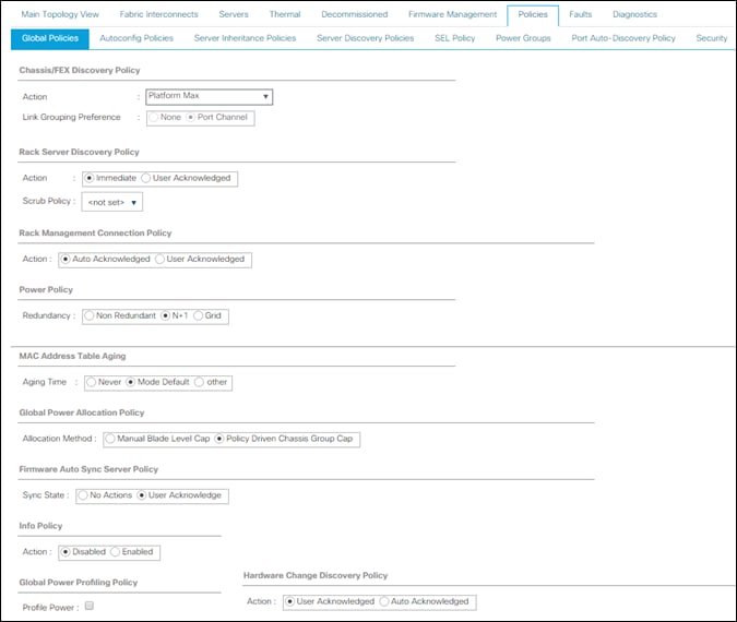
Configure NTP Server
To configure the NTP server for the Cisco UCS environment, follow these steps:
1. Select Admin tab on the left site.
2. Select Time Zone Management.
3. Select Time Zone.
4. Under Properties select your time zone.
5. Select Add NTP Server.
6. Enter the IP address of the NTP server.
7. Select OK.
Figure 20 Adding a NTP Server – Summary
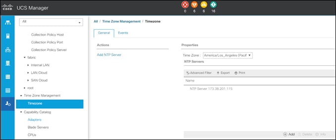
Enable Fabric Interconnect A Ports for Server
To enable server ports, follow these steps:
1. Select the Equipment tab.
2. Select Equipment > Fabric Interconnects > Fabric Interconnect A (primary) > Fixed Module.
3. Click Ethernet Ports section.
4. Select Ports 1-12, right-click and then select Configure as Server Port.
5. Click Yes and then click OK.
6. Repeat the same steps for Fabric Interconnect B.
Enable Fabric Interconnect A Ports for Uplinks
To enable uplink ports, follow these steps:
1. Select the Equipment tab on the left site.
2. Select Equipment > Fabric Interconnects > Fabric Interconnect A (primary) > Fixed Module.
3. Click Ethernet Ports section.
4. Select Ports 49-52, right-click and then select Configure as Uplink Port.
5. Click Yes and then click OK.
6. Repeat the same steps for Fabric Interconnect B.
Create Port Channel for Fabric Interconnect A/B
To create Port Channels to the connected Nexus 93180YC-EX switches, follow these steps:
1. Select the LAN tab in the left pane of the Cisco UCS Manager GUI.
2. Go to LAN > LAN Cloud > Fabric A > Port Channels and right-click Create Port Channel.
3. Type in ID 10.
4. Type in vPC10 in the Name field.
5. Click Next.
6. Select the available ports on the left 49-52 and assign them with >> to Ports in the Port Channel.
Figure 21 Create Port Channel
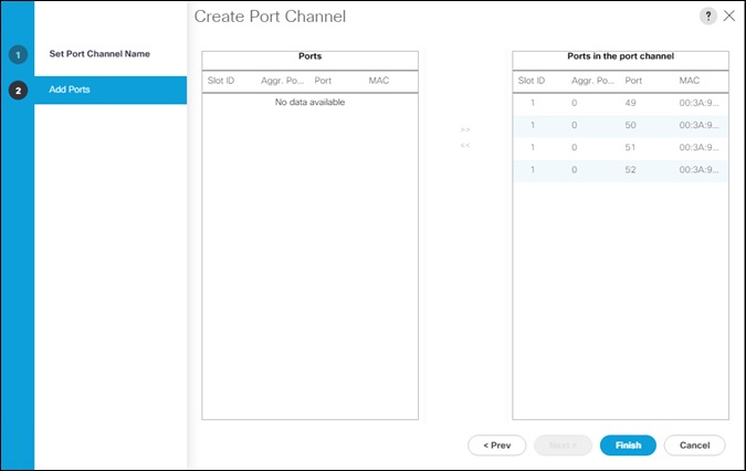
7. Click Finish and then click OK.
8. Repeat the same steps for Fabric B under LAN > LAN Cloud > Fabric B > Port Channels and right-click Create Port Channel.
9. Type in ID 11.
10. Type in vPC11 in the Name field.
11. Click Next.
12. Select the available ports on the left 49-52 and assign them with >> to Ports in the Port Channel.
13. Click Finish and then click OK.
Label Each Server for Identification
To label each chassis for better identification, follow these steps:
1. Select the Equipment tab on the left site.
2. Select Chassis > Chassis 1.
3. In the Properties section on the right go to User Label and add Slicestor 1/2 to the field.
4. Repeat the previous steps for Chassis 2 – 6 by using the following labels (Table 7):
| Chassis |
Name |
| Chassis 1 |
Slicestor 1/2 |
| Chassis 2 |
Slicestor 3/4 |
| Chassis 3 |
Slicestor 5/6 |
| Chassis 4 |
Slicestor 7/8 |
| Chassis 5 |
Slicestor 9/10 |
| Chassis 6 |
Slicestor 11/12 |
5. Now select Chassis 1 -> Servers -> Server 1.
6. In the Properties section on the right go to User Label and add Slicestor 1 to the field.
7. Repeat steps 1-6 for Server 2 and each chassis by using the following labels (Table 8):
| Chassis |
Server |
Name |
| Chassis 1 |
Server 1 |
Slicestor 1 |
| Chassis 1 |
Server 2 |
Slicestor 2 |
| Chassis 2 |
Server 3 |
Slicestor 3 |
| Chassis 2 |
Server 4 |
Slicestor 4 |
| Chassis 3 |
Server 5 |
Slicestor 5 |
| Chassis 3 |
Server 6 |
Slicestor 6 |
| Chassis 4 |
Server 7 |
Slicestor 7 |
| Chassis 4 |
Server 8 |
Slicestor 8 |
| Chassis 5 |
Server 9 |
Slicestor 9 |
| Chassis 5 |
Server 10 |
Slicestor 10 |
| Chassis 6 |
Server 11 |
Slicestor 11 |
| Chassis 6 |
Server 12 |
Slicestor 12 |
Create KVM IP Pool
To create a KVM IP Pool, follow these steps:
1. Select the LAN tab on the left site.
2. Go to LAN > Pools > root > IP Pools and right-click Create Block of IPv4 Addresses.
3. Type in IBMCOS-IP as Name.
4. (Optional) Enter a Description of the MAC Pool.
5. Set Assignment Order as Sequential.
6. Click Next and then Add.
7. Enter an IP Address in the From field.
8. Enter Size 20.
9. Enter your Subnet Mask.
10. Fill in your Default Gateway.
11. Enter your Primary DNS and Secondary DNS if needed.
12. Click OK.
13. Click Next, click Finish and then click OK.
Figure 22 Create Block of IPv4 Addresses
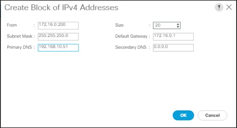
Create MAC Pool
To create a MAC Pool, follow these steps:
1. Select the LAN tab on the left site.
2. Go to LAN > Pools > root > Mac Pools and right-click Create MAC Pool.
3. Type in IBMCOS-MAC as Name.
4. (Optional) Enter a Description of the MAC Pool.
5. Set Assignment Order as Sequential.
6. Click Next.
7. Click Add.
8. Specify a starting MAC address.
9. Specify a size of the MAC address pool, which is sufficient to support the available server resources, for example, 100.
Figure 23 Create a Block of MAC Addresses
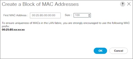
10. Click OK.
11. Click Finish and then click OK.
Create UUID Pool
To create a UUID Pool, follow these steps:
1. Select the Servers tab on the left site.
2. Go to Servers > Pools > root > UUID Suffix Pools and right-click Create UUID Suffix Pool.
3. Type in IBMCOS-UUID as Name.
4. (Optional) Enter a Description of the UUID Pool.
5. Set Assignment Order to Sequential and click Next.
6. Click Add.
7. Specify a starting UUID Suffix.
8. Specify a size of the UUID suffix pool, which is sufficient to support the available server resources, for example, 20.
Figure 24 Create a Block of UUID Suffixes
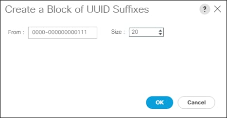
9. Click OK.
10. Click Finish and then click OK.
Create Network Control Policy
To enable Network Control Policies, follow these steps:
1. Select the LAN tab in the left pane of the Cisco UCS Manager GUI.
2. Go to LAN > Policies > root > Network Control Policies and right-click Create Network-Control Policy.
3. Type in IBMCOS-CDP in the Name field.
4. (Optional) Enter a description in the Description field.
5. Click Enabled under CDP.
6. Click Only Native Vlan under MAC Register Mode.
7. Leave everything else untouched and click OK.
8. Click OK.
Figure 25 Create Network Control Policy
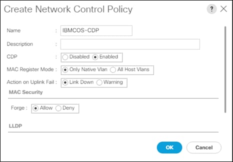
VLAN Setup
In the next section, we’re going to create different VLANs for the different vNICs according to Table 9:
| VLAN Name |
VLAN ID |
| Management |
100 |
| Data |
101 |
| Client |
102 |
To enable Network Control Policies, follow these steps:
1. Select the LAN tab in the left pane of the Cisco UCS Manager GUI.
2. Go to LAN > LAN Cloud > VLANs right-click Create VLANs.
3. Type in Management for VLAN Name/Prefix and 100 for VLAN IDs.
4. Repeat the same steps for VLAN 101 and 102.
5. Leave everything else untouched and click OK.
6. Click OK and then click OK again.
Figure 26 Create VLAN
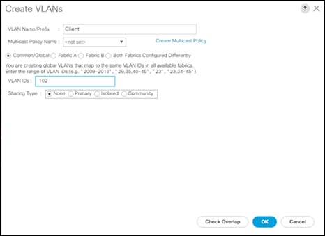
VLAN Group Policy
With the VLAN group policy we want to make sure that VLANs Management and Client gets transported over both port-channels but VLAN Storage keeps under both Fabric Interconnects. To create a VLAN Group Policy, follow these steps:
1. Select the LAN tab in the left pane of the Cisco UCS Manager GUI.
2. Go to LAN > LAN Cloud > VLAN Groups right-click Create VLAN Group.
3. Type in IBMCOS-VLANGroup for Name.
4. Select all VLANs and click Native for VLAN Management.
Figure 27 Create VLAN Group
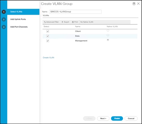
5. Click Next and then click Next again.
6. Select both port channel and move them to Selected Port Channels.
Figure 28 Select Port Channels
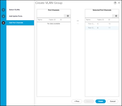
7. Click Finish and then click OK again.
vNIC Template Setup
The next step is to create the appropriate vNIC templates. For IBM COS we need to create three vNIC. These vNICs will handle Management, Storage, and Client traffic.
| vNIC Name |
VLAN ID |
VLAN Name |
Fabric Interconnect |
Failover |
MTU Size |
Adapter Policy |
| Management |
100 |
Management |
A |
X |
1500 |
VMware |
| Data-A |
101 |
Data |
A |
X |
9000 |
IBMCOS |
| Data-B |
101 |
Data |
B |
X |
9000 |
IBMCOS |
| Client-A |
102 |
Client |
A |
X |
9000 |
IBMCOS |
| Client-B |
102 |
Client |
B |
X |
9000 |
IBMCOS |
To create the appropriate vNIC, follow these steps:
1. Select the LAN tab in the left pane of the Cisco UCS Manager GUI.
2. Go to LAN > Policies > root > vNIC Templates and right-click Create vNIC Template.
3. Type in Management in the Name field.
4. (Optional) Enter a description in the Description field.
5. Click Fabric A as Fabric ID and enable failover.
6. Click Updating Template as Template Type.
7. Select Management as VLAN and click Native VLAN.
8. Type in 1500 for MTU Size.
9. Select IBMCOS-MAC as MAC Pool.
10. Select IBMCOS-CDP as Network Control Policy.
11. Click OK and then click OK again.
12. Repeat steps 1-11 for the other vNICs Data-A, Data-B, Client-A and Client-B according to Table 4.
Figure 29 Setup vNIC Template for vNIC Data-A
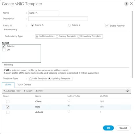
Adapter Policy Setup
To create a specific adapter policy for ClevOS, follow these steps:
1. Select the Server tab in the left pane of the Cisco UCS Manager GUI.
2. Go to Servers > Policies > root > Adapter Policies and right-click Create Ethernet Adapter Policy.
3. Type in IBMCOS in the Name field.
4. (Optional) Enter a description in the Description field.
5. Under Resources type in the following values:
a. Transmit Queues: 8
b. Ring Size: 4096
c. Receive Queues: 8
d. Ring Size: 4096
e. Completion Queues: 16
f. Interrupts: 32
6. Under Options enable Receive Side Scaling (RSS) and Accelerated Receive Flow Steering.
7. Click OK and then click OK again.
Figure 30 Adapter Policy for IBM
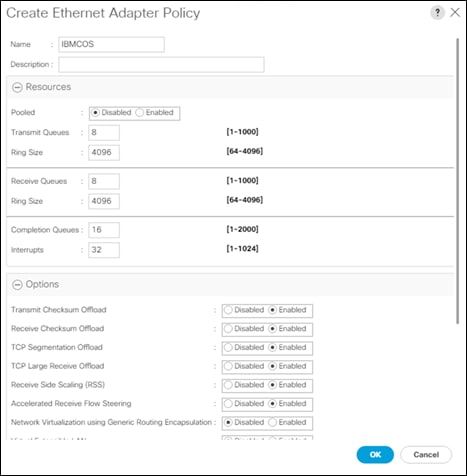
Create LAN Connectivity Policy
To simplify the setup of your network within the Service Profiles create a LAN Connectivity Policy by following these steps:
1. Select the LAN tab in the left pane of the Cisco UCS Manager GUI.
2. Go to LAN > Policies > root > LAN Connectivity Policies and right-click Create LAN Connectivity Policy.
3. Type in IBMCOS-LAN in the Name field.
4. (Optional) Enter a description in the Description field.
5. Click Add.
6. Click Use vNIC Template and type Management under Name.
7. Select vNIC Template Management and Adapter Policy VMware according to Table 4.
8. Click OK and repeat the same steps for vNIC Data-A, Data-B, Client-A and Client-B according to Table 4.
9. Click OK, then click OK, and click OK again.
Figure 31 Create LAN Connectivity Policy
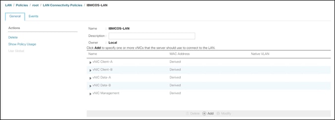
Create vNIC Placement Policy
To make sure that you get the maximum network performance we create a vNIC Placement Policy to distribute the vNICs in a linear order over the vCONs (see https://www.cisco.com/c/en/us/td/docs/unified_computing/ucs/ucs-manager/GUI-User-Guides/Server-Mgmt/4-0/b_Cisco_UCS_Manager_Server_Mgmt_Guide_4_0/b_Cisco_UCS_Manager_Server_Mgmt_Guide_4_0_chapter_01011.html#concept_y13_5tk_ndb) It might be not that important if there is only one adapter but could be interesting when two adapters in a single-node Cisco UCS S3260 M5 are in use. To create the vNIC Placement Policy, follow these steps:
1. Select the Server tab in the left pane of the Cisco UCS Manager GUI.
2. Go to Servers > Policies > root > vNIC/vHBA Placement Policies and right-click Create Placement Policy.
3. Type in IBMCOS-Placement in the Name field.
4. Select Linear Ordered under Virtual Slot Mapping Scheme.
5. Double-Click on each Transport line of the Virtual Slot and just keep ethernet in it.
6. Click OK and then click OK again.
Figure 32 Create vNIC Placement Policy
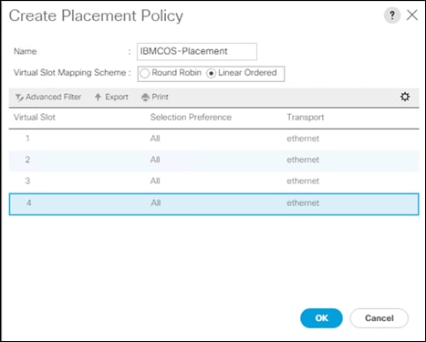
Boot Policy Setup
To create a Boot Policy, follow these steps:
1. Select the Servers tab in the left pane.
2. Go to Servers > Policies > root > Boot Policies and right-click Create Boot Policy.
3. Type in IBMCOS-Boot in the Name field.
4. (Optional) Enter a description in the Description field.
5. Click Local Devices > Add Local LUN and leave Any as default.
6. Click OK.
7. Click CIMC Mounted vMedia > Add CIMC Mounted CD/DVD
8. Click OK.
9. Click OK.
Figure 33 Create Boot Policy
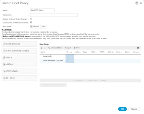
Create Maintenance Policy Setup
To setup a Maintenance Policy, follow these steps:
1. Select the Servers tab in the left pane.
2. Go to Servers > Policies > root > Maintenance Policies and right-click Create Maintenance Policy.
3. Type in IBMCOS-Maint in the Name field.
4. (Optional) Enter a description in the Description field.
5. Click User Ack under Reboot Policy.
6. Click OK and then click OK again.
Figure 34 Create Maintenance Policy
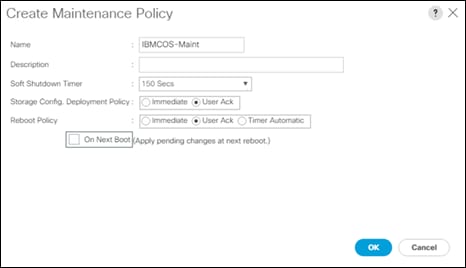
Create Power Control Policy Setup
To create a Power Control Policy, follow these steps:
1. Select the Servers tab in the left pane.
2. Go to Servers > Policies > root > Power Control Policies and right-click Create Power Control Policy.
3. Type in IBMCOS-Power in the Name field.
4. (Optional) Enter a description in the Description field.
5. Click No Cap.
6. Click OK and then click OK again.
Figure 35 Create Power Control Policy
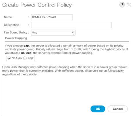
Create Host Firmware Package
To create a Host Firmware Policy, follow these steps:
1. Select the Servers tab in the left pane.
2. Go to Servers > Policies > root > Host Firmware Packages and right-click Create Host Firmware Package.
3. Type in IBMCOS-FW in the Name field.
4. (Optional) Enter a description in the Description field.
5. Under Rack Package select 4.1(1c)C.
6. Deselect Local Disk.
7. Click OK and then click OK again.
Figure 36 Create Host Firmware Policy
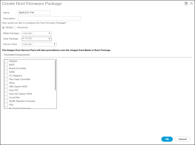
Create vMedia Policy in Cisco UCS Manager
To simplify the installation of the hardware agnostic IBM image, create the vMedia policy for the IBM Service Profile and follow these steps:
1. Select the Servers tab in the left pane.
2. Go to Servers > Policies > root > vMedia Policies and right-click Create vMedia Policy.
3. Type in IBMCOS-vMedia in the Name field.
4. (Optional) Enter a description in the Description field.
5. Click Add.
6. Type in IBMCOS-ISO in the Name field.
7. (Optional) Enter a description in the Description field.
8. Click CDD for Device Type.
9. Click HTTP for Protocol.
10. Type in the Hostname/IP Address.
11. Type in clevos-3.14.11.39-allinone-usbiso.iso for Remote File.
12. Type in Remote Path.
13. Click OK, click OK again, and then click OK.
Figure 37 Create vMedia Mount for IBM COS Boot Image
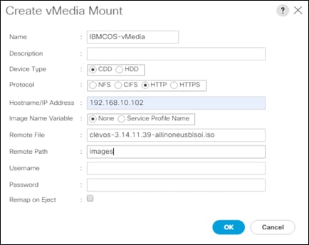
Creating Storage Profiles
Next, you’ll create the Disk Group Policy and Storage Profile for the boot devices for the rear end SATA SSDs.
Creating Disk Group Policy for Boot Devices
To create the Disk Group Policy from the rear end SATA SSDs, follow these steps:
1. Select Storage in the left pane of the Cisco UCS Manager GUI.
2. Go to Storage > Storage Policies > root > Disk Group Policies and right-click Create Disk Group Policy.
3. Type in IBMCOS-Boot in the Name field.
4. (Optional) Enter a description in the Description field.
5. Select RAID 1 Mirrored for RAID Level.
6. Click Disk Group Configuration (Manual).
7. Click Add.
8. Type in 201 as slot number.
9. Repeat the step for slot number 202.
10. Under Virtual Drive Configuration select Write Back Good Bbu under Write Cache Policy.
11. Click OK and then click OK again.
Figure 38 Create Disk Group Policy for Boot Device
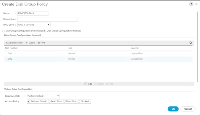
Create Storage Profile
To create the Storage Profile, follow these steps:
1. Select Storage in the left pane of the Cisco UCS Manager GUI.
2. Go to Storage > Storage Profiles and right-click Create Storage Profile.
3. Type in IBMCOS-Disk in the Name field.
4. (Optional) Enter a description in the Description field.
5. Click Add under Local LUN.
6. Type in Boot in the Name field.
7. Click Expand To Available.
8. Select IBMCOS-Boot under Select Disk Group Configuration.
9. Click OK, then click OK, and click OK again.
Creating Chassis Profiles
Before starting building the Service Profiles you need to create Chassis Policies and Profiles to configure the Cisco UCS S3260 Chassis.
Create Chassis Firmware Package
To create a Chassis Firmware Package, follow these steps:
1. Select the Chassis tab in the left pane of the Cisco UCS Manager GUI.
2. Go to Chassis > Policies > root > Chassis Firmware Package and right-click Create Chassis Firmware Package.
3. Type in IBMCOS-CHFW in the Name field.
4. (Optional) Enter a description in the Description field.
5. Select 4.1(1c)C from the drop-down list of Chassis Package.
6. Deselect Local Disk from the Excluded Components.
7. Select OK and then click OK again.
Figure 39 Create Chassis Firmware Package
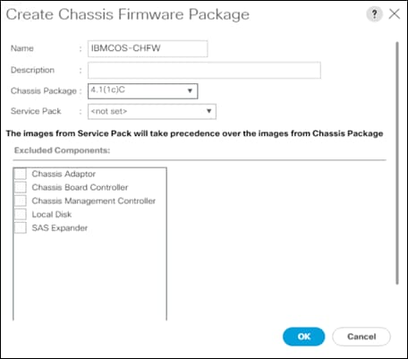
Create Chassis Maintenance Policy
To create a Chassis Maintenance Policy, follow these steps:
1. Select the Chassis tab in the left pane of the Cisco UCS Manager GUI.
2. Go to Chassis > Policies > root > Chassis Maintenance Policies and right-click Create Chassis Maintenance Policy.
3. Type in IBMCOS-Maint in the Name field.
4. (Optional) Enter a description in the Description field.
5. Select OK and then click OK again.
Figure 40 Create Chassis Maintenance Policy

Create Compute Connection Policy
To create a Compute Connection Policy, follow these steps:
1. Select the Chassis tab in the left pane of the Cisco UCS Manager GUI.
2. Go to Chassis > Policies > root > Compute Connection Policies and right-click Create Compute Connection Policy.
3. Type in IBMCOS-Conn in the Name field.
4. (Optional) Enter a description in the Description field.
5. Select Single Server Single SIOC.
6. Select OK and then click OK again.
Figure 41 Create Compute Connection Policy
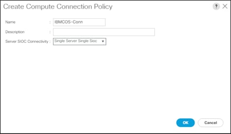
Create Disk Zoning Policy
To create a Disk Zoning Policy, follow these steps:
1. Select the Chassis tab in the left pane of the Cisco UCS Manager GUI.
2. Go to Chassis > Policies > root > Disk Zoning Policies and right-click Create Disk Zoning Policy.
3. Type in IBMCOS-Zone in the Name field.
4. (Optional) Enter a description in the Description field.
5. Click Add.
6. Under Ownership click Dedicated.
7. Under Server select Server 1 and under Controller select Controller 1.
8. Add Slot 1-14 under Slot Range.
Figure 42 Create Disk Zoning
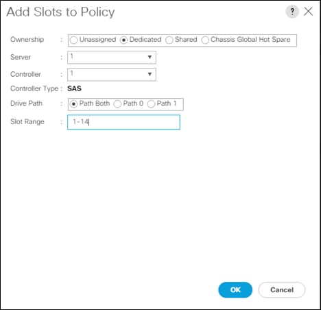
9. Repeat steps 5-8 according to the following table:
Table 11 Disk Zoning S3260
| Server |
Controller |
Slot Range |
| 1 |
1 |
1-14 |
| 1 |
2 |
15-28 |
| 2 |
1 |
29-42 |
| 2 |
2 |
43-56 |
10. Select OK and then click OK again.
Create Sas Expander Configuration Policy
To create a Sas Expander Configuration Policy, follow these steps:
1. Select the Chassis tab in the left pane of the Cisco UCS Manager GUI.
2. Go to Chassis > Policies > root > Sas Expander Configuration Policies and right-click Create Sas Expander Configuration Policy.
3. Type in IBMCOS-SAS in the Name field.
4. (Optional) Enter a description in the Description field.
5. Select OK and then click OK again.
Figure 43 Create Sas Expander Configuration Policy
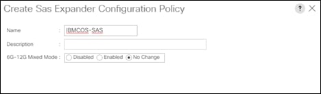
Create Chassis Profile Template
To create a Chassis Profile Template, follow these steps:
1. Select the Chassis tab in the left pane of the Cisco UCS Manager GUI.
2. Go to Chassis > Chassis Profile Templates and right-click Create Chassis Profile Template.
3. Type in IBMCOS-Chassis in the Name field.
4. Under Type, select Updating Template.
5. Optional) Enter a description in the Description field.
6. Click Next.
7. Under the radio button Chassis Maintenance Policy, select your previously created Chassis Maintenance Policy.
8. Click Next.
9. Under the radio button Chassis Firmware Package, Compute Connection Policy, and Sas Expander Configuration Policy, select your previously created Policies.
10. Click Next.
11. Under the radio button Disk Zoning Policy, select your previously created Disk Zoning Policy.
12. Click Finish and then click OK.
Create Chassis Profile from Template
To create the Chassis Profiles from the previous created Chassis Profile Template, follow these steps:
1. Select the Chassis tab in the left pane of the Cisco UCS Manager GUI.
2. Go to Chassis > Chassis Profile Templates and select “IBMCOS-Chassis” you created previously.
3. Then right click to select Create Chassis Profiles from Template.
4. Type in S3260-Chassis in the Name field.
5. Leave the Name Suffix Starting Number untouched.
6. Enter 6 for the Number of Instances for all connected Cisco UCS S3260 Storage Server.
7. Click OK and then click OK again.
Figure 44 Create Chassis Profile from Template
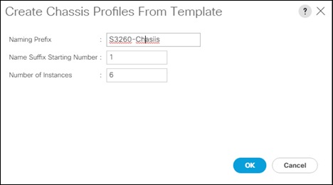
Associate Chassis Profiles
To associate all previous created Chassis Profile, follow these steps:
1. Select the Chassis tab in the left pane of the Cisco UCS Manager GUI.
2. Go to Chassis > Chassis Profiles and select S3260-Chassis1.
3. Right-click Change Chassis Profile Association.
4. Under Chassis Assignment, choose Select existing Chassis from the drop-down list.
5. Under Available Chassis, select ID 1.
6. Click OK and then click OK again.
7. Repeat steps 1-6 for the other two Chassis Profiles by selecting the IDs 2 – 6.
Figure 45 Associate Chassis Profile

8. A pop-up will appear on the top right side. Click Chassis Profiles and Acknowledge All Chassis profiles.
9. Click Apply.
10. Click OK.
Create Service Profile Template
Create Service Profile Template
1. Select Servers in the left pane of the Cisco UCS Manager GUI.
2. Go to Servers > Service Profile Templates and right-click Create Service Profile Template.
Identify Service Profile Template
1. Type in IBMCOS in the Name field.
2. Click Updating Template in Type.
3. In the UUID Assignment section, select the IBMCOS-UUID Pool.
4. (Optional) Enter a description in the Description field.
5. Click Next.
Storage Provisioning
1. Go to the Storage Profile Policy tab and select the Storage Profile IBMCOS-Disk.
2. Click Next.
Networking
1. Select the Use Connectivity Policy radio button for the option How would you like to configure LAN connectivity?
2. Select the Connectivity Policy IBMCOS-LAN
3. Click Next to continue with SAN Connectivity.
4. Select No vHBA for How would you like to configure SAN Connectivity?
5. Click Next to continue with Zoning.
6. Click Next to continue with vNIC/vHBA Placement.
7. Select IBMCOS-Placement Policy under Select Placement
8. Select all five vNIC interfaces on the left and select vCon 1 on the right.
9. Select the >> button to move the vNICs over to vCon 1.
10. Change the order of the vNICs under vCon 1 with Management first, Data-A second, Data-B third, Client-B fourth and Client-A fifth.[2]
11. Click Next to continue with vMedia Policy.
vMedia Policy
1. Select IBMCOS-vMedia from the vMedia Policy Menu.
2. Click Next.
Server Boot Order
1. Select IBMCOS-Boot from the Boot Policy Menu.
2. Click Next.
Server Maintenance
1. Select the Maintenance Policy IBMCOS-Maint under Maintenance Policy.
2. Click Next.
Firmware Management
1. Select the Firmware Policy IBMCOS-FW under Firmware Management
2. Click Next,
Operational Policies
1. Under Management IP Address click the Outband tab and select IBMCOS-IP under Management IP Address Policy.
2. Under Power Control Policy Configuration select IBMCOS-Power.
3. Click Finish.
Create Service Profiles from Template
Create the appropriate Service Profiles from the previous Service Profile Template. To create all 12 profiles for the IBM Server, follow these steps:
1. Select Servers from the left pane of the Cisco UCS Manager GUI.
2. Go to Servers > Service Profiles and right-click Create Service Profiles from Template.
3. Type in Slicestor in the Name Prefix field.
4. Type 1 for Name Suffix Starting Number.
5. Type 12 for Number of Instances.
6. Choose IBMCOS under Service Profile Template.
7. Click OK.
Associate Service Profiles
To associate the service profiles, follow these steps:
1. Right-click the service profile Slicestor1 and choose Change Service Profile Association.
2. Server Assignment should be Select Existing Server.
3. Select Chassis ID 1, Slot 1.
4. Click OK and Yes and OK.
5. Repeat the steps for the all Service Profiles counting up the Chassis ID and Slot ID corresponding with the service profile.
The formal setup of the Cisco UCS Manager environment and both Cisco Nexus 93180YC-EX switches is now finished and the installation of the IBM Cloud Object Storage ClevOS software will continue.
This section provides detailed information about the installation of vManager for IBM COS on VMware vCenter and Slicestors with embedded Accessers on Cisco UCS S3260 M5. It is assumed that there is an existing ESXi host installed and this document doesn’t explain the installations steps for an ESXi host.
Deployment of Virtual IBM COS Manager on VMware vCenter
To deploy the virtual IBM COS Manager on VMware vCenter, follow these steps:
1. Log into your local vCenter and select the ESXi host you want to use for deploying the virtual appliance.
2. Select under Actions – Deploy OVF Template.
3. Select the template clevos-3.14.11.39-manager.ova on your local filesystem and then click Next to select your datacenter.
Figure 46 Select the Data Center for the Location of the Appliance
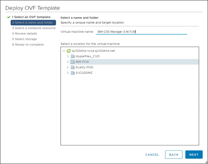
4. Click Next to choose your resource and then click Next.
Figure 47 Select the Resource for the Appliance
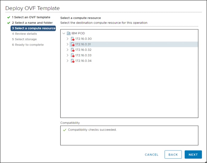
5. Review the details and click Next to select the storage.
Figure 48 Select the Storage
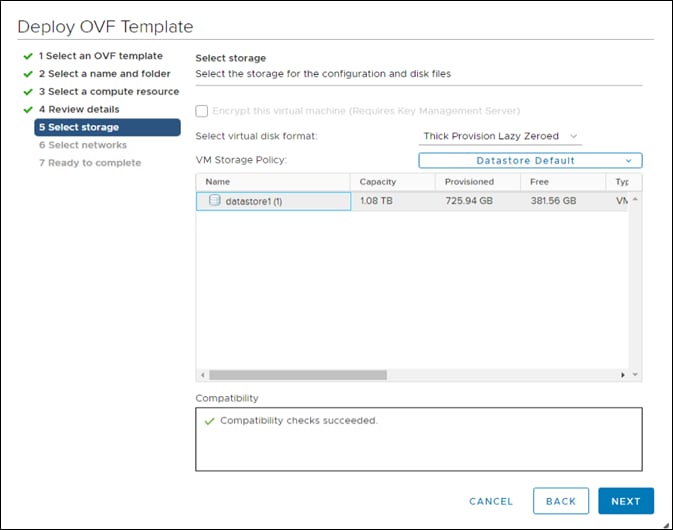
6. Click Next and select the network.
Figure 49 Select the Network to use for the Virtual Appliance
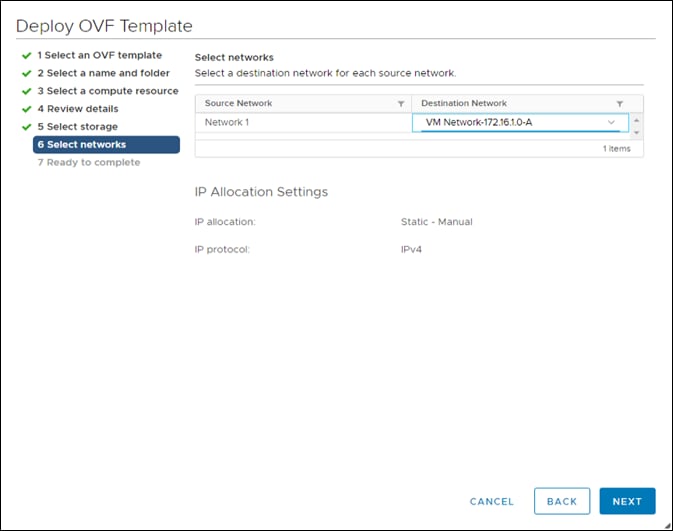
7. Click Next, review the summary and then click Finish to deploy the virtual appliance.
8. When the deployment finished, right-click the virtual machine and go to Edit Settings to change the memory to 64 GB, then start the virtual machine and launch the remote console.
Figure 50 Launching the Remote Console
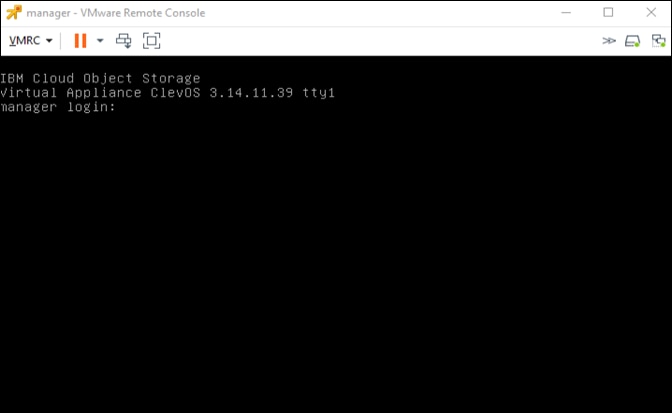
9. At the ClevOS Manager login prompt, provide the following credentials:
a. Username - localadmin
b. Password - password
10. When logged in at the local console, change the password by following the prompts:
a. manager# password
b. Current password:
i. New password: <type in the new, secure password here>
ii. Retype new password: <re-enter the new password from above here>
iii. Password change successful
iv. manager#
![]() It is highly recommended to change the password at first login. In addition to following good security protocol, ClevOS will not enable Secure Shell (SSH) remote access until the default password has been changed.
It is highly recommended to change the password at first login. In addition to following good security protocol, ClevOS will not enable Secure Shell (SSH) remote access until the default password has been changed.
11. ClevOS uses a configuration shell that can be entered by entering the command edit. Enter the configuration shell and input the following commands to perform initial configuration steps, making changes in your environment as necessary:
manager# edit
manager (working)#
Check the network interface
manager (working)# port
PORT ADDRESS MAX SPEED STATUS
eth0 00:50:56:bc:dd:98 10000 Mbps disconnected
12. Configure the interface that is part of the channel data:
manager (working)# channel data port eth0
13. Establish an IP address for the data channel:
manager (working)# channel data ip 172.16.1.100 netmask 255.255.255.0 gateway 172.16.1.1
14. Configure the hostname for the appliance:
manager (working)# system hostname manager
manager (working)# system dns 192.168.10.51
15. Provide some basic location details. This increases the randomness during the private key generation process:
manager (working)# system organization cisco city sjc state ca country us
16. Once all information has been entered suitable to the deployment, activate the configuration:
manager (working)# activate
17. Wait for activation to complete. Once activation has completed, navigate in a browser to the ClevOS Manager ip address configured up above 172.16.1.100.
If the webserver responds and the following screen appears, initial first-time console setup has completed.
Figure 51 Log in screen for Cloud Object Storage Manager
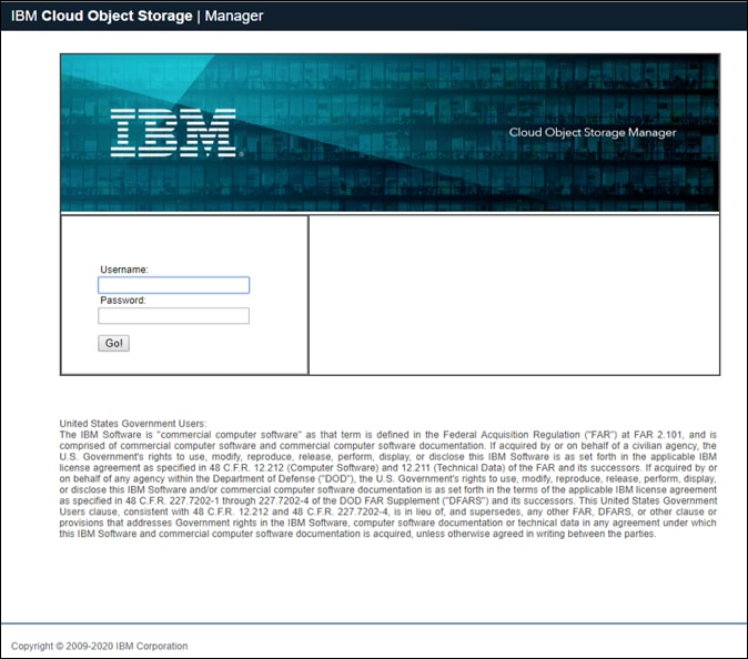
18. First time console configuration should now be complete on the ClevOS Manager Node. To finish initial web UI configuration, follow these steps:
a. At the IBM Cloud Object Storage Manager login prompt at the IP address configured above, provide the following credentials:
i. Username - admin
ii. Password - password
19. When logged in web interface, accept the license agreement and input the name of the license acceptor. Select the button titled Accept IBM & non-IBM Licenses.
Figure 52 Accept IBM Licenses
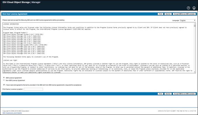
20. Select the radio button Create a new system and then click the Begin.
Figure 53 Create new system

21. At the Admin Password screen, enter a new password in the both fields to change the default and then select Save and Continue.
Figure 54 Enter New Password
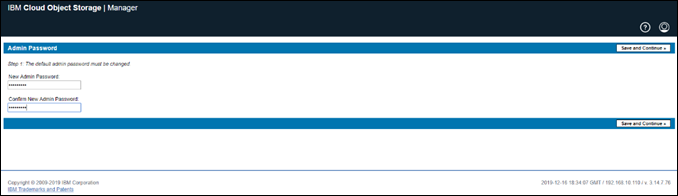
22. At the Create Sites screen, modify as much information as desired and then click Finish.
Figure 55 Create Site
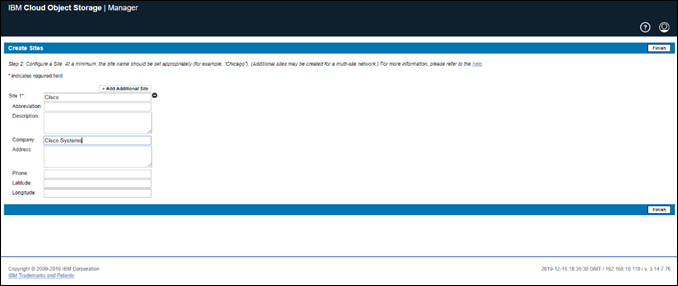
The initial set up of the virtual appliance Manager is now finished.
Deployment of IBM COS Slicestor on Cisco UCS S3260 M5
To install ClevOS onto the Cisco UCS S3260 M5 to be used as the IBM Cloud Object Storage Slicestor, follow these steps:
1. Select the Servers button on the left side.
2. Navigate to Servers > Service Profiles > root > slicestor1 from the exposed, left tree.
3. Select KVM Console underneath the Actions section of the right-hand pane. Accept any prompts or follow any links until the KVM Console is present. This could require a Java software upgrade or disabling pop ups in the browser.
4. Wait until the ClevOS Installer appears and select then #1 Perform Automatic Installation.
Figure 56 ClevOS Installer
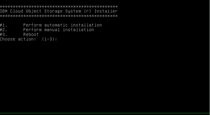
5. Select option #2 Factory Install (Erase all disks and install) at the next ClevOS installation screen that appears.
6. When making the last selection, a new prompt will appear warning that all disks will be erased during this process. To confirm this data destructive behavior, type in erase and hit enter.
Figure 57 Disk Erase Choice
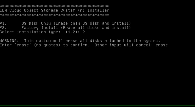
7. At the next ClevOS installation screen, select the desired source image, #3 CLEVOS-3.14.11.39~SLICESTOR and press Enter.
Figure 58 Select SLICESTOR Installation
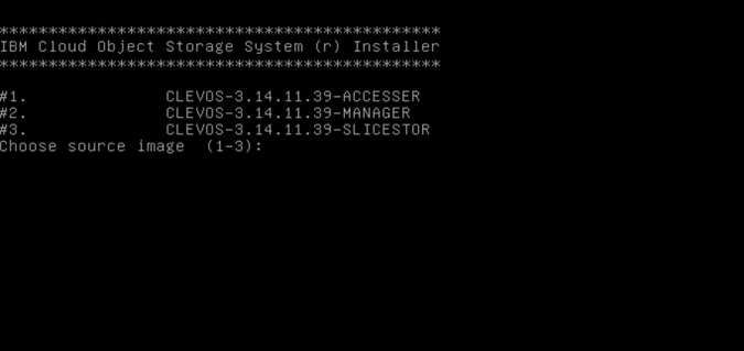
8. When the system has been rebooted and the following screen appears, ClevOS installation has completed for node slicestor1.
Figure 59 Login Screen for slicestor1
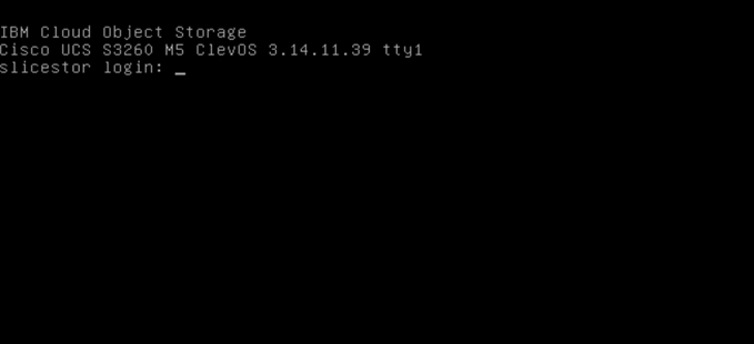
9. Installation has finished on the IBM COS Slicestor node. To finish initial Slicestor node first-time configuration, follow these steps:
a. At the ClevOS Slicestor login prompt, provide the following credentials:
i. Username - localadmin
ii. Password - password
10. When logged in at the local console, change the password by following the prompts:
a. slicestor# password
b. Current password:
i. New password: <type in the new, secure password here>
ii. Retype new password: <re-enter the new password from above here>
iii. Password change successful
iv. slicestor#
![]() It is highly recommended to change the password at first login. In addition to following good security pro-tocol, ClevOS will not enable Secure Shell (SSH) remote access until the default password has been changed.
It is highly recommended to change the password at first login. In addition to following good security pro-tocol, ClevOS will not enable Secure Shell (SSH) remote access until the default password has been changed.
11. ClevOS uses a configuration shell that can be entered by entering the command edit. Enter the configuration shell and input the following commands to perform initial configuration steps, making changes in your environment as necessary:
slicestor# edit
slicestor (working)#
12. Check the network interface:
slicestor (working)# port
PORT ADDRESS MAX SPEED STATUS
p5p1 00:25:b5:00:00:37 40000 Mbps disconnected[3]
p5p2 00:25:b5:00:00:38 40000 Mbps disconnected
p5p3 00:25:b5:00:00:39 40000 Mbps disconnected
p5p4 00:25:b5:00:00:3a 40000 Mbps disconnected
p5p5 00:25:b5:00:00:3b 40000 Mbps disconnected
13. Configure the interface that will be part of the channel data and client. Interface p5p1 is internal management, p5p2 is Data-A, p5p3 is Data-B, p5p4 is Client-B and p5p5 is Client-A:
slicestor (working)# channel data port p5p2,p5p3
slicestor (working)# channel client port p5p4,p5p5
![]() For Slicestor nodes 2,4,6,8,10, and 12 the port information starts with p6p instead of p5p.
For Slicestor nodes 2,4,6,8,10, and 12 the port information starts with p6p instead of p5p.
14. Establish an IP address for all channels:
slicestor (working)# channel data ip 172.16.1.101 netmask 255.255.255.0 gateway 172.16.1.1
slicestor (working)# channel client 172.16.2.101 netmask 255.255.255.0
slicestor (working)# channel data bonding active-backup
slicestor (working)# channel client bonding active-backup
slicestor (working)# channel data bondmtu 9000
slicestor (working)# channel client bondmtu 9000
slicestor (working)# system hostname slicestor1
slicestor (working)# system dns 192.168.10.51
15. Provide some basic location details. This increases the randomness during the private key generation process:
slicestor (working)# system organization cisco city sjc state ca country us
16. Provide the IP address of the previously configured ClevOS Manager. Accept any errors about manager certificates which occur as a result of the network interface not yet being up by entering y and skip entering a manager prefix by selecting the enter key at the prompt:
slicestor (working)# manager ip 172.16.1.100
ERROR: couldn’t retrieve manager certificate: curl returned exit code 7
Automatically accept the manager certificate when it is available? [y/N]: y
Enter prefix of manager fingerprint to verify (press enter to skip)
>
slicestor (working)#
17. Once all information has been entered suitable to the deployment, activate the configuration:
slicestor (working)# activate
Please wait, this may take several minutes….
check OK
activate OK
slicestor1#
18. Repeat steps 1-17 to set up the remaining Slicestors 2 -12, make sure to modify the IP address and hostname according to the table below:
Table 12 IP Address and Hostnames
| Service Profile |
IP Address Data |
IP Address Client |
Hostname |
| Slicestor1 |
172.16.1.101 |
172.16.2.101 |
slicestor1 |
| Slicestor2 |
172.16.1.102 |
172.16.2.102 |
slicestor2 |
| Slicestor3 |
172.16.1.103 |
172.16.2.103 |
slicestor3 |
| Slicestor4 |
172.16.1.104 |
172.16.2.104 |
slicestor4 |
| Slicestor5 |
172.16.1.105 |
172.16.2.105 |
slicestor5 |
| Slicestor6 |
172.16.1.106 |
172.16.2.106 |
slicestor6 |
| Slicestor7 |
172.16.1.107 |
172.16.2.107 |
slicestor7 |
| Slicestor8 |
172.16.1.108 |
172.16.2.108 |
slicestor8 |
| Slicestor9 |
172.16.1.109 |
172.16.2.109 |
slicestor9 |
| Slicestor10 |
172.16.1.110 |
172.16.2.110 |
slicestor10 |
| Slicestor11 |
172.16.1.111 |
172.16.2.111 |
slicestor11 |
| Slicestor12 |
172.16.1.112 |
172.16.2.112 |
slicestor12 |
Before starting to configure the IBM COS dsNet it is useful to verify the current install in terms of any hardware issues, network performance and base disk performance. Execute the three main test procedures to verify each:
1. Hardware stress test with stress-ng. stress-ng can stress various subsystems of a computer. It can stress load CPU, cache, disk, memory, socket and pipe I/O, scheduling and much more.
2. Network performance test with iperf to verify the current line speed and the MTU size on both channels data and client.
3. Disk performance test with fio to verify the maximum performance for a single disk and an entire node with 28 disks. Block size will be 4KB and 4MB with tests running random read/write and sequential read/write.
Since IBM COS is a closed system there is usually no way to install tools like stress-ng and fio and it isn’t recommended doing the following procedure in production. For our base configuration verification, we manipulate the sources.list file in ClevOS to be able to install the tools for verification. After a reboot of each system the default configuration is again available, and all previous installed tools are removed.
Preparation of Slicestor nodes for base configuration verification
To run all the previous explained tests follow these steps:
1. Log into slicestor1:
C:\Users\Administrator>ssh localadmin@172.16.1.101
localadmin@172.16.1.101's password:
IBM Cloud Object Storage
Cisco UCS S3260 M5 ClevOS 3.14.11.39
Last login: Tue Dec 17 16:42:05 2019 from 192.168.10.2
IBM Cloud Object Storage Device Shell
Type '?' or 'help' to get the list of available commands.
slicestor1# su
root@slicestor1:~#
2. Create a new sources.list file in /etc/apt/
deb http://deb.debian.org/debian stretch main
deb-src http://deb.debian.org/debian stretch main
deb http://deb.debian.org/debian-security/ stretch/updates main
deb-src http://deb.debian.org/debian-security/ stretch/updates main
deb http://deb.debian.org/debian stretch-updates main
deb-src http://deb.debian.org/debian stretch-updates main
3. Run an update on sources.list
root@slicestor1:~# apt update
Ign:1 http://deb.debian.org/debian stretch InRelease
Get:2 http://deb.debian.org/debian-security stretch/updates InRelease [94.3 kB]
Get:3 http://deb.debian.org/debian stretch-updates InRelease [91.0 kB]
Get:4 http://deb.debian.org/debian stretch Release [118 kB]
Get:5 http://deb.debian.org/debian stretch Release.gpg [2,365 B]
Get:6 http://deb.debian.org/debian-security stretch/updates/main Sources [202 kB]
Get:7 http://deb.debian.org/debian-security stretch/updates/main amd64 Packages [509 kB]
Get:8 http://deb.debian.org/debian-security stretch/updates/main Translation-en [224 kB]
Get:9 http://deb.debian.org/debian stretch-updates/main Sources [13.8 kB]
Get:10 http://deb.debian.org/debian stretch-updates/main amd64 Packages [27.9 kB]
Get:11 http://deb.debian.org/debian stretch-updates/main Translation-en [11.9 kB]
Get:12 http://deb.debian.org/debian stretch/main Sources [6,747 kB]
Get:13 http://deb.debian.org/debian stretch/main amd64 Packages [7,086 kB]
Get:14 http://deb.debian.org/debian stretch/main Translation-en [5,385 kB]
Fetched 20.5 MB in 4s (4,780 kB/s)
Reading package lists... Done
Building dependency tree
Reading state information... Done
74 packages can be upgraded. Run 'apt list --upgradable' to see them.
root@slicestor1:~#
4. Install stress-ng and fio:
root@slicestor1:~# apt -y install stress-ng fio
5. Repeat steps 1-4 for all other Slicestors.
Running Hardware Stress Test
stress-ng will stress test a computer system in various selectable ways. It was designed to exercise various physical subsystems of a computer as well as the various operating system kernel interfaces. stress-ng is used to determine any hardware failures of all installed components. With the following options of stress-ng you are able to test all components of each system/Slicestor:
· --cpu 28 -> start 28 workers on each CPU in parallel to stress the CPU
· --vm 12 -> start 12 workers writing to the allocated memory
· --hdd 8 -> start 8 workers continually writing, reading and removing temporary files to disks
· --fork 12 -> start 12 workers continually forking children that immediately exit
· --switch 4 -> start 4 workers that send messages via pipe to a child to force context switching
· --metrics-brief -> enable metrics and only output metrics that are non-zero
· --timeout 72h -> run stress-ng for 72h
To start stress-ng on all Slicestors, run the following:
root@slicestor2:~# stress-ng --cpu 28 --vm 12 --hdd 8 --fork 12 --switch 4 --metrics-brief --timeout 72h
stress-ng: info: [40842] dispatching hogs: 28 cpu, 12 fork, 8 hdd, 4 switch, 12 vm
stress-ng: info: [40842] cache allocate: default cache size: 16896K
stress-ng: info: [40842] successful run completed in 259200.21s (3 days, 0.21 secs)
stress-ng: info: [40842] stressor bogo ops real time usr time sys time bogo ops/s bogo ops/s
stress-ng: info: [40842] (secs) (secs) (secs) (real time) (usr+sys time)
stress-ng: info: [40842] cpu 766562460 259200.06 6545040.52 2204.33 2957.42 117.08
stress-ng: info: [40842] fork 435809194 259200.00 102570.10 72893.80 1681.36 2483.75
stress-ng: info: [40842] hdd 70060574400 259200.12 18684.38 1859778.80 270295.30 37296.75
stress-ng: info: [40842] switch 237516056928 259200.00 57736.82 954618.78 916342.81 234617.22
stress-ng: info: [40842] vm 17432982670 259200.07 2736544.17 36064.43 67256.86 6287.57
You should see similar results on all Slicestor nodes, which indicates that the tested hardware is fully functional.
IBM COS Network Verification
To verify that jumbo frames are correctly implemented in the environment and the link speed is equivalent to 25 Gbps, ClevOS has iperf installed by default on all nodes. Before moving on to more complex activities, it can be beneficial to verify the network as operating as intended. This test will also determine if SSH was configured correctly. To test if MTU 9000 is correctly configured, follow these steps:
1. Connect to slicestor1.
C:\Users\Administrator>ssh localadmin@172.16.1.101
localadmin@172.16.1.101's password:
IBM Cloud Object Storage
Cisco UCS S3260 M5 ClevOS 3.14.11.39
Last login: Tue Dec 17 16:42:05 2019 from 192.168.10.2
IBM Cloud Object Storage Device Shell
Type '?' or 'help' to get the list of available commands.
slicestor1# su
root@slicestor1:~#
2. Temporarily disable the firewall so that network throughput testing may occur.
root@slicestor1:~# service iptables stop
[ ok ] Stopping iptables: iptables.
root@slicestor1:~#
3. Start iperf in server mode.
root@slicestor1:~# iperf -s -p 5002
------------------------------------------------------------
Server listening on TCP port 5002
TCP window size: 85.3 KByte (default)
------------------------------------------------------------
4. Repeat steps 1 - 5 on the second Slicestor at IP address 172.16.1.102 to arrive at a similar secure shell prompt:
C:\Users\Administrator>ssh localadmin@172.16.1.102
localadmin@172.16.1.102's password:
IBM Cloud Object Storage
Cisco UCS S3260 M5 ClevOS 3.14.11.39
Last login: Tue Dec 17 16:19:25 2019 from 192.168.10.2
IBM Cloud Object Storage Device Shell
Type '?' or 'help' to get the list of available commands.
slicestor2# su
root@slicestor2:~# service iptables stop
[ ok ] Stopping iptables: iptables.
root@slicestor2:~#
5. The following command iperf -c 172.16.1.101 -P 4 -m -d -p 5002 will run iperf in bidirectional client mode on the data interface. There are two things this will test: total throughput and MTU size. The frame size is marked in yellow and the total throughput is marked in red. Repeat the same test on the client interface.
root@slicestor2:~# iperf -c 172.16.1.101 -P 4 -m -d -p 5002
------------------------------------------------------------
Server listening on TCP port 5002
TCP window size: 85.3 KByte (default)
------------------------------------------------------------
------------------------------------------------------------
Client connecting to 172.16.1.101, TCP port 5002
TCP window size: 1.33 MByte (default)
------------------------------------------------------------
[ 7] local 172.16.1.102 port 34806 connected with 172.16.1.101 port 5002
[ 6] local 172.16.1.102 port 34800 connected with 172.16.1.101 port 5002
[ 5] local 172.16.1.102 port 34802 connected with 172.16.1.101 port 5002
[ 8] local 172.16.1.102 port 34804 connected with 172.16.1.101 port 5002
[ 4] local 172.16.1.102 port 5002 connected with 172.16.1.101 port 45448
[ 9] local 172.16.1.102 port 5002 connected with 172.16.1.101 port 45450
[ 10] local 172.16.1.102 port 5002 connected with 172.16.1.101 port 45452
[ 11] local 172.16.1.102 port 5002 connected with 172.16.1.101 port 45454
[ ID] Interval Transfer Bandwidth
[ 7] 0.0-10.0 sec 7.18 GBytes 6.17 Gbits/sec
[ 7] MSS size 8948 bytes (MTU 8988 bytes, unknown interface)
[ 6] 0.0-10.0 sec 7.19 GBytes 6.17 Gbits/sec
[ 6] MSS size 8948 bytes (MTU 8988 bytes, unknown interface)
[ 5] 0.0-10.0 sec 7.18 GBytes 6.17 Gbits/sec
[ 5] MSS size 8948 bytes (MTU 8988 bytes, unknown interface)
[ 8] 0.0-10.0 sec 7.18 GBytes 6.17 Gbits/sec
[ 8] MSS size 8948 bytes (MTU 8988 bytes, unknown interface)
[SUM] 0.0-10.0 sec 28.7 GBytes 24.7 Gbits/sec
[ 4] 0.0-10.0 sec 4.79 GBytes 4.11 Gbits/sec
[ 4] MSS size 8948 bytes (MTU 8988 bytes, unknown interface)
[ 9] 0.0-10.0 sec 4.79 GBytes 4.11 Gbits/sec
[ 9] MSS size 8948 bytes (MTU 8988 bytes, unknown interface)
[ 10] 0.0-10.0 sec 14.4 GBytes 12.3 Gbits/sec
[ 10] MSS size 8948 bytes (MTU 8988 bytes, unknown interface)
[ 11] 0.0-10.0 sec 4.79 GBytes 4.11 Gbits/sec
[ 11] MSS size 8948 bytes (MTU 8988 bytes, unknown interface)
[SUM] 0.0-10.0 sec 28.7 GBytes 24.7 Gbits/sec
root@slicestor2:~# iperf -c 172.16.2.101 -P 4 -m -d -p 5002
------------------------------------------------------------
Server listening on TCP port 5002
TCP window size: 85.3 KByte (default)
------------------------------------------------------------
------------------------------------------------------------
Client connecting to 172.16.2.101, TCP port 5002
TCP window size: 1.75 MByte (default)
------------------------------------------------------------
[ 5] local 172.16.2.102 port 57818 connected with 172.16.2.101 port 5002
[ 6] local 172.16.2.102 port 57812 connected with 172.16.2.101 port 5002
[ 7] local 172.16.2.102 port 57814 connected with 172.16.2.101 port 5002
[ 8] local 172.16.2.102 port 57816 connected with 172.16.2.101 port 5002
[ 4] local 172.16.2.102 port 5002 connected with 172.16.2.101 port 53882
[ 9] local 172.16.2.102 port 5002 connected with 172.16.2.101 port 53884
[ 10] local 172.16.2.102 port 5002 connected with 172.16.2.101 port 53886
[ 11] local 172.16.2.102 port 5002 connected with 172.16.2.101 port 53888
[ ID] Interval Transfer Bandwidth
[ 5] 0.0-10.0 sec 4.79 GBytes 4.12 Gbits/sec
[ 5] MSS size 8948 bytes (MTU 8988 bytes, unknown interface)
[ 6] 0.0-10.0 sec 9.59 GBytes 8.23 Gbits/sec
[ 6] MSS size 8948 bytes (MTU 8988 bytes, unknown interface)
[ 7] 0.0-10.0 sec 4.80 GBytes 4.12 Gbits/sec
[ 7] MSS size 8948 bytes (MTU 8988 bytes, unknown interface)
[ 8] 0.0-10.0 sec 9.58 GBytes 8.23 Gbits/sec
[ 8] MSS size 8948 bytes (MTU 8988 bytes, unknown interface)
[SUM] 0.0-10.0 sec 28.8 GBytes 24.7 Gbits/sec
[ 4] 0.0-10.0 sec 9.58 GBytes 8.23 Gbits/sec
[ 4] MSS size 8948 bytes (MTU 8988 bytes, unknown interface)
[ 9] 0.0-10.0 sec 9.58 GBytes 8.23 Gbits/sec
[ 9] MSS size 8948 bytes (MTU 8988 bytes, unknown interface)
[ 10] 0.0-10.0 sec 4.79 GBytes 4.12 Gbits/sec
[ 10] MSS size 8948 bytes (MTU 8988 bytes, unknown interface)
[ 11] 0.0-10.0 sec 4.79 GBytes 4.11 Gbits/sec
[ 11] MSS size 8948 bytes (MTU 8988 bytes, unknown interface)
[SUM] 0.0-10.0 sec 28.8 GBytes 24.7 Gbits/sec
6. Perform this test on an all ClevOS Slicestor nodes as desired to confirm that jumbo frames are enabled on all servers.
7. When testing has completed, re-enable the firewall issuing the command service iptables start.
root@slicestor1:~# service iptables start
[ ok ] Starting iptables: iptables.
Base Disk Performance
In the final verification test, to know the base performance of the physical backed, run fio on a single disk and on all 28 disks under a single node. It is important to know the performance for random read/write and sequential read/write.
Base Disk Performance Testing
Before testing the base performance, make sure the drive cache is enabled under ClevOS by running the following:
root@slicestor1:~# for i in {{a..z},aa,ab}; do sdparm --get=WCE /dev/sd$i | xargs; done | nl
1 /dev/sda: HGST HUH721010AL42C0 A3Z4 WCE 1 [cha: y, def: 0, sav: 0]
2 /dev/sdb: HGST HUH721010AL42C0 A3Z4 WCE 1 [cha: y, def: 0, sav: 0]
3 /dev/sdc: HGST HUH721010AL42C0 A3Z4 WCE 1 [cha: y, def: 0, sav: 0]
4 /dev/sdd: HGST HUH721010AL42C0 A3Z4 WCE 1 [cha: y, def: 0, sav: 0]
5 /dev/sde: HGST HUH721010AL42C0 A3Z4 WCE 1 [cha: y, def: 0, sav: 0]
6 /dev/sdf: HGST HUH721010AL42C0 A3Z4 WCE 1 [cha: y, def: 0, sav: 0]
7 /dev/sdg: HGST HUH721010AL42C0 A3Z4 WCE 1 [cha: y, def: 0, sav: 0]
8 /dev/sdh: HGST HUH721010AL42C0 A3Z4 WCE 1 [cha: y, def: 0, sav: 0]
9 /dev/sdi: HGST HUH721010AL42C0 A3Z4 WCE 1 [cha: y, def: 0, sav: 0]
10 /dev/sdj: HGST HUH721010AL42C0 A3Z4 WCE 1 [cha: y, def: 0, sav: 0]
11 /dev/sdk: HGST HUH721010AL42C0 A3Z4 WCE 1 [cha: y, def: 0, sav: 0]
12 /dev/sdl: HGST HUH721010AL42C0 A3Z4 WCE 1 [cha: y, def: 0, sav: 0]
13 /dev/sdm: HGST HUH721010AL42C0 A3Z4 WCE 1 [cha: y, def: 0, sav: 0]
14 /dev/sdn: HGST HUH721010AL42C0 A3Z4 WCE 1 [cha: y, def: 0, sav: 0]
15 /dev/sdo: HGST HUH721010AL42C0 A3Z4 WCE 1 [cha: y, def: 0, sav: 0]
16 /dev/sdp: HGST HUH721010AL42C0 A3Z4 WCE 1 [cha: y, def: 0, sav: 0]
17 /dev/sdq: HGST HUH721010AL42C0 A3Z4 WCE 1 [cha: y, def: 0, sav: 0]
18 /dev/sdr: HGST HUH721010AL42C0 A3Z4 WCE 1 [cha: y, def: 0, sav: 0]
19 /dev/sds: HGST HUH721010AL42C0 A3Z4 WCE 1 [cha: y, def: 0, sav: 0]
20 /dev/sdt: HGST HUH721010AL42C0 A3Z4 WCE 1 [cha: y, def: 0, sav: 0]
21 /dev/sdu: HGST HUH721010AL42C0 A3Z4 WCE 1 [cha: y, def: 0, sav: 0]
22 /dev/sdv: HGST HUH721010AL42C0 A3Z4 WCE 1 [cha: y, def: 0, sav: 0]
23 /dev/sdw: HGST HUH721010AL42C0 A3Z4 WCE 1 [cha: y, def: 0, sav: 0]
24 /dev/sdx: HGST HUH721010AL42C0 A3Z4 WCE 1 [cha: y, def: 0, sav: 0]
25 /dev/sdy: HGST HUH721010AL42C0 A3Z4 WCE 1 [cha: y, def: 0, sav: 0]
26 /dev/sdz: HGST HUH721010AL42C0 A3Z4 WCE 1 [cha: y, def: 0, sav: 0]
27 /dev/sdaa: HGST HUH721010AL42C0 A3Z4 WCE 1 [cha: y, def: 0, sav: 0]
28 /dev/sdab: HGST HUH721010AL42C0 A3Z4 WCE 1 [cha: y, def: 0, sav: 0]
With WCE=1 the write cache for each disk is enabled. If WCE=0, please enable the write cache with:
root@slicestor1:~# for i in {{a..z},aa,ab}; do sdparm --set=WCE /dev/sd$i | xargs; done
To run a fio test on a single disk, run the following:
root@slicestor1:~# fio --filename=/dev/sda --name=read-4k --rw=read --ioengine=libaio --bs=4k --numjobs=1 --direct=1 --randrepeat=0 --iodepth=1 --runtime=300 --ramp_time=5 --size=100G --group_reporting
Delete the cache of the system by running after each fio test:
root@slicestor1:~# sync; echo 3 > /proc/sys/vm/drop_caches
To run now a fio test on 28 disks, run the following:
root@slicestor1:~# disk_list=/dev/sda,/dev/sdb,/dev/sdc,/dev/sdd,/dev/sde,/dev/sdf,/dev/sdg,/dev/sdh,/dev/sdi,/dev/sdj,/dev/sdk,/dev/sdl,/dev/sdm,/dev/sdn,/dev/sdo,/dev/sdp,/dev/sdq,/dev/sdr,/dev/sds,/dev/sdt,/dev/sdu,/dev/sdv,/dev/sdw,/dev/sdx,/dev/sdy,/dev/sdz,/dev/sdaa,/dev/sdab
root@slicestor1:~# genfio -d $disk_list -b 4k -r 300 -p -m read -x read4k.fio
root@slicestor1:~# fio read4k.fio
A summary of the base performance is listed in Table 13.
Table 13 Base disk performance
|
|
Single Disk |
28 Disks |
||
|
|
4 KB |
4 MB |
4 KB |
4 MB |
| Random Read |
625 KB/s |
165 MB/s |
9.1 MB/s |
3253 MB/s |
| Random Write |
2.3 MB/s |
168 MB/s |
45 MB/s |
3213 MB/s |
| Sequential Read |
175 MB/s |
237 MB/s |
3094 MB/s |
6625 MB/s |
| Sequential Write |
134 MB/s |
236 MB/s |
2507 MB/s |
6624 MB/s |
The verification of hardware testing, network and disk performance is now done. Reboot each Slicestor node to remove all installed packages from the test.
IBM COS dsNet Setup
After you have installed ClevOS on all of your appliances, you need to perform a GUI configuration. This GUI configuration is accomplished through the Manager GUI.
1. Open a web browser and navigate to the IP address of the IBM COS Manager 172.16.1.100 and log in with the credentials created previously.
2. Select Configure from the top navigation bar and observe 12 devices pending approval. This happens automatically after following the previous console command manager ip 172.16.1.100.
Figure 60 Bulk Approve Slicestors
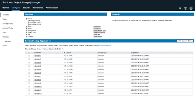
3. Select the checkbox directly to the left of the column header Hostname. This will select all pending devices for approval. Leave the Slicestor Storage Engine as Packed. Select the button for Bulk Approve / Deny.
Figure 61 Bulk Device Registration
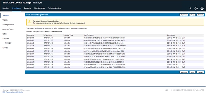
4. At the Bulk Device Registration screen, click Approve.
Figure 62 Bulk Edit Device Site
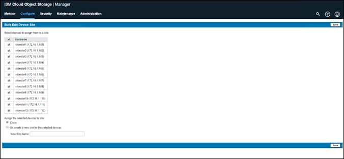
5. At the Bulk Edit Device Site screen, select the checkbox directly to the left of the column header Hostname. Next, select the radio button for the previously created site name, Cisco. Click Save.
6. (Optional) At the Bulk Edit Device Alias screen, provide any alias beyond the hostname for each node if desired. Once complete, or if no alias required, click Save.
Device registration should now be complete and all nodes added to the Site.
Configure IBM COS to Sync with an NTP Server
It is critical to have time in sync both across all COS nodes. In order to configure the IBM COS dsNet to sync with an NTP server, follow these steps:
1. Select the Administration tab from the topmost navigation bar and scroll down to System NTP Configuration and select Configure.
2. Select the middle radio button next to Manager and External NTP. Next, enter the IP address of the configured NTP server in the External NTP Servers dialog box. Click Update.
Figure 63 System NTP Configuration
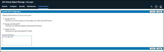
Change Drive Health Configuration
To prevent wrong drive state reporting for a dual node Cisco UCS S3260 M5 where each blade hosts 28 drives instead of 56 drives, change the Drive Health Configuration follow these steps:
1. Select the Administration tab from the topmost navigation bar and scroll down to Drive Health Configuration and click Configure.
2. Under Warning configure 29 and under Error configure 33.
Figure 64 Drive Health Configuration
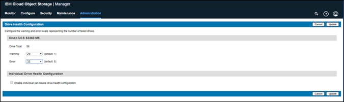
Configure IBM COS Provisioning API
In order to create new vaults (sometimes referred to as buckets), it is important to enable the Provisioning API. In order to configure the IBM COS Provisioning API, follow these steps:
1. Open a web browser and navigate to the IP address of the IBM COS Manager 172.16.1.100 and log in with the credentials created previously.
2. Select the Administration tab and scroll down to Provisioning API Configuration and click Configure.
3. Select the radio button next to Create and Delete. Click Update.
Figure 65 Provisioning API Configuration
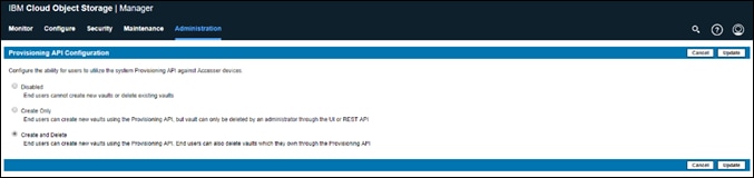
Create a Storage Pool
A storage pool is defined by a logical grouping of Slicestor devices used to store vault data. A vault is initially created on a storage pool, and then may be expanded by creating new storage pool or pools on additional devices. Additional pools must be a multiple width of the original pool. A Slicestor device may only be a member of a single storage pool. To create a storage pool, follow these steps:
1. Select Create Storage Pool from underneath the Summary section.
2. Provide the Storage Pool a name in the Name field.
3. From the Width drop-down list, select a width equal to the total number of Slicestors contained in the pool.
4. Select Enable the embedded Accesser service on all Slicestor devices belonging to this storage pool to enable Embedded Accesser.
5. Leave Name Index Format default as Version 4.
6. Verify that all 12 Slicestors are selected in the Devices section and then click Save.
Figure 66 Create a Storage Pool
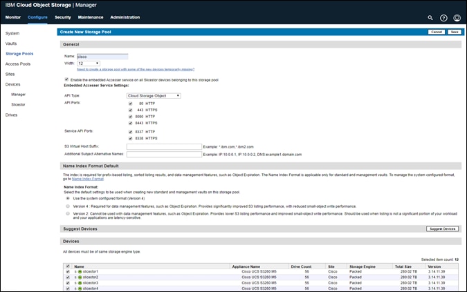
Create Vault for User Access
A Vault is a collection of data that is stored in one logical container, across a defined Storage Pool of Slicestor devices. Multiple Vaults may be linked to the same Storage Pool. There are several considerations for vault creation:
· In order to define a vault, the quantity of Slicestor devices (width) and the Threshold must be identified. The width and the threshold will interactively determine the maximum usable capacity. The number of devices in a Storage Pool must always be a multiple of the width, for example a Storage Pool with 16 Slicestor devices, the width must be either 16 or 8.
· The vault threshold, always less than the width, will determine the reliability of the vault, i.e. how many slices must be minimally present to accurately read data. The Manager UI will allow any value between 1 and the Vault Width except for Dispersal Mode.
· The write threshold should be set larger than the threshold. If the number of slices available is less than or equal to the write threshold, the vault will be read-only. If the number of slices is greater than the write threshold but less than or equal to the alert threshold, the vault will remain fully functional but will trigger an alert.
To create a vault, follow these steps:
1. Click Create Vault from underneath the Summary section.
2. Provide a Vault name in the Name field.
3. From the Width drop-down list, select the desired width, in this case 12.
4. From the Threshold drop-down list, select the desired threshold, in this case 8.
5. From the Write Threshold drop-down list, select the desired write threshold, in this case 10.
6. From the Alert Level drop-down list, select the desired alert level, in this case 11.
7. Make certain to leave the checkbox next to Enable Secure Slice Technology checked.
8. Leave all other options at default and make any additional desired changes.
9. Click Save button.
Figure 67 Create a Standard Vault
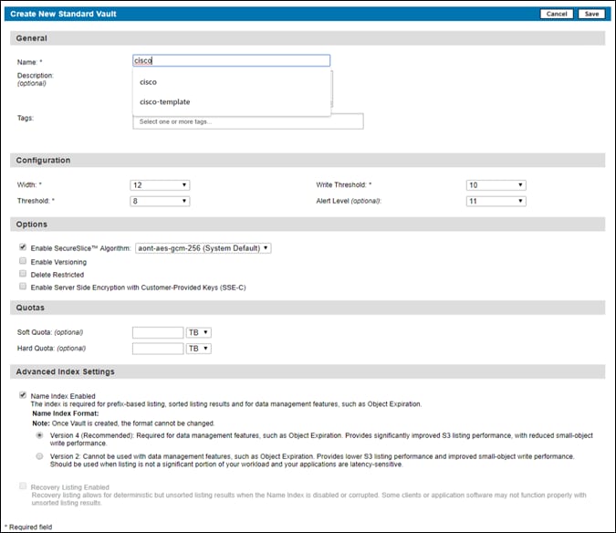
Create Vault Template for Provisioning
A Vault Template can be useful for vault or bucket creation via API. The first step for enabling this functionality is to create a vault.
To create a vault template, follow these steps:
1. Click the Configure tab.
2. Click Configure from underneath the Template Management section.
3. Within the Vault Template section beneath Template Management, click Cisco-Pool from the drop-down list to Select Storage Pool for Vault Template. Click Create.
4. Provide a Vault Template name in the Name field.
5. Under Configuration select Width=12, Threshold=8, Write Threshold=10, and Alert Level=11
6. Make certain to leave the checkbox next to Enable Secure Slice Technology checked.
7. Leave all other options at default and make any additional desired changes.
8. Click Save.
Figure 68 Create Vault Template
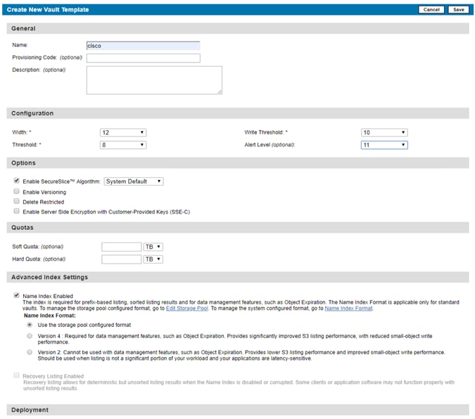
9. Return to the Template Management section by clicking the Configure tab from the topmost navigation bar and then click Configure from underneath the Template Management.
10. Select the radio button next to the newly created vault and then click Update.
Figure 69 Template Management
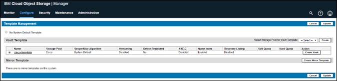
Enable Access Key Authentication
Enabling Access Key Authentication will enable an end user to use an Access Key and Secret Key to authenticate for vault access in IBM COS. This is the standard access for object storage in general. To enable access key authentication, follow these steps:
1. From the main screen, click the Security tab. Click Configure.
2. Select the checkbox next to the Enable access key authentication and click Update.
Figure 70 Enable Authentication Mechanisms
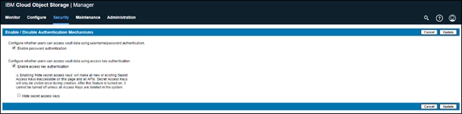
Create a User
It is necessary to create an additional user for object access. There are protections in place to keep system administrators from being able to access data to avoid system compromise. To create a user, follow these steps:
To create a new user, follow these steps:
1. Click the Security tab.
2. Click Create Account from underneath the Accounts section.
3. Provide a name in the Name field.
4. In the Authentication section, clear the box. This will disable the user’s ability to authenticate with a username and password.
5. Select Vault Provisioner as Role.
6. In the Vault Access section, you should be in the No Access tab. Select the box next to the vault that you created earlier and then click Move to Read/Write. This gives the user read and write access to the vault.
7. For the Device Access tab, make sure that the No Access buttons are selected.
8. For the Site Access tab, leave the defaults.
9. Click Save.
Figure 71 Create New Account
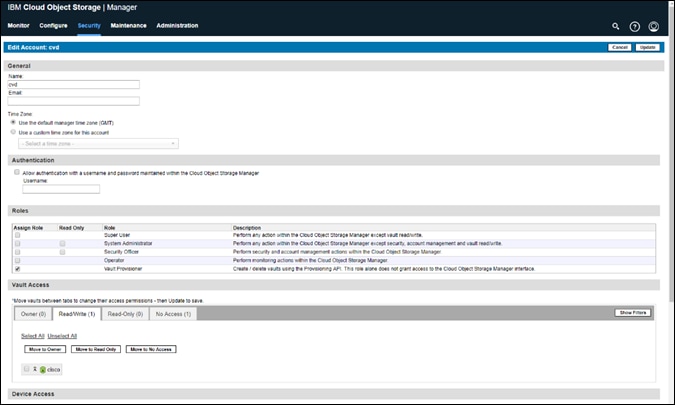
Generate Access Key ID
To generate an Access Key ID for the user to manage objects within IBM COS, follow these steps:
1. Click the Security tab if needed after creating the new user account.
2. Select the newly created user from beneath the Accounts section.
3. Find the Access Key Authentication section and click Change Keys.
4. From the Edit Access Keys for Account screen, click Generate New Access Key.
5. Once the key is created, click the Click to Show Secret Access Key.
6. Make note of the Access Key ID and the Secret Access Key.
7. You can exit out of this screen by selecting the IBM CLOUD OBJECT STORAGE text in the upper left-hand corner of your web browser.
Figure 72 Access Key for User
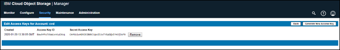
The formal setup of IBM COS is now finished and next is validating the solution as detailed in the next chapter.
The validation of the whole solution is divided into three sections:
· Functional Object Storage Access Validation with awscli.
· High Availability Testing
· Initial Performance S3 Benchmark with COSBench
Functional Object Storage Access Validation
This section describes one of the methods to access the newly created vault. For many end users, access may utilize the API, a GUI based program, or a program from the command line. For simplicity, a command line example is provided below.
Prerequisites
· A Linux system on the same network as the IBM COS Embedded Accessers (a virtual machine will suffice)
· The ‘awscli’ tool. Installation of this tool will be demonstrated with CentOS based ‘yum’
· Access to either a local repository or the internet for remote application installation
To test IBM COS access functionality, follow these steps:
1. Log into your Linux/CentOS client in the same subnet as the Embedded Accessers.
2. Update the apt repositories providing user password where necessary:
root@client1 ~]# yum -y update
3. Install ‘awscli’
root@client1 ~]# yum -y install awscli
4. Create a new configuration file at ~/.aws/credentials with the following information. Use whichever tool is preferred, such as ‘vim’, however for simplicity, the file and credentials are created using the echo command. Modify access key id and secret access key as necessary:
[root@client1 ~]# aws configure
AWS Access Key ID [None]: mXbmDcRQmLibGINFKlQy
AWS Secret Access Key [None]: f4tXbB7s7d3UsMEhyuZvDP6qfFJULhFhaRJ0Gp0e
Default region name [None]:
Default output format [None]:
5. Test credentials, access, and the presence of the cisco vault with the following command and output:
root@client1 ~]# aws --endpoint-url=http://172.16.2.101 s3 ls
2018-12-16 13:11:21 cisco
6. List the contents of the cisco vault (return output should be empty):
root@client1 ~]# aws --endpoint-url=http://172.16.2.101 s3 ls cisco
7. Upload a file to the cisco bucket:
[root@client1 ~]# aws --endpoint-url=http://172.16.2.101 s3 cp /root/0.4.2.c3.zip s3://cisco/
upload: ./0.4.2.c3.zip to s3://cisco/0.4.2.c3.zip
8. List vault contents and observe the presence of the newly uploaded file:
[root@client1 ~]# aws --endpoint-url=http://172.16.2.101 s3 ls cisco
2020-01-20 05:44:10 33680308 0.4.2.c3.zip
9. Create a new vault or bucket:
aws --endpoint-url=http://172.16.2.101 s3api create-bucket --bucket cisco1
10. Copy the previously uploaded file from cisco bucket to cisco1 bucket:
[root@client1 ~]# aws --endpoint-url=http://172.16.2.101 s3 cp s3://cisco/0.4.2.c3.zip s3://cisco1/
copy: s3://cisco/0.4.2.c3.zip to s3://cisco1/0.4.2.c3.zip
11. Move the newly copied file on cisco1 vault back to cisco under a new name:
[root@client1 ~]# aws --endpoint-url=http://172.16.2.101 s3 mv s3://cisco1/0.4.2.c3.zip s3://cisco/test.zip
move: s3://cisco1/0.4.2.c3.zip to s3://cisco/test.zip
11. Verify that Cisco-Vault1 is now empty and the existence of two equally sized Ubuntu ISO files:
aws --endpoint-url=http://172.16.2.101 s3 ls s3://cisco1
IBM COS High Availability Testing
It is important for business continuity to help ensure high availability of the hardware and software stack. Some of these features are built into the Cisco UCS Infrastructure and enabled by the software stack and some of these features are possible from the IBM COS Storage software itself. In order to properly test for high availability, the following considerations were given priority:
· The IBM COS deployment will process a reasonable amount of load when the fault is triggered. Total throughput will be recorded from the COSBench interface.
· Only a single fault will be triggered at any given time. Double failure is not a part of this consideration.
· Performance degradation is acceptable and even expected, but there should be no business interruption tolerated. The underlying infrastructure components should continue to operate within the remaining environment.
· The tests were conducted with the IBM COS configuration with Embedded Accesser.
The following High Availability tests were performed:
1. Cisco Nexus 93180YC-EX Switch A failure
2. Cisco UCS 6454 Fabric Interconnect B failure
3. IBM COS Manager VM failure
4. Cisco UCS S3260 M5 – IBM COS slicestor1 disk failure
5. Cisco UCS S3260 M5 – IBM COS slicestor1 node failure
The COSBench application will be configured to send a steady stream of data to a load balancer HAProxy setup. The load balancer has a front-end IP address and all 12 client IP from the embedded Accesser as back-end IP.
Figure 73 High Availability Testing
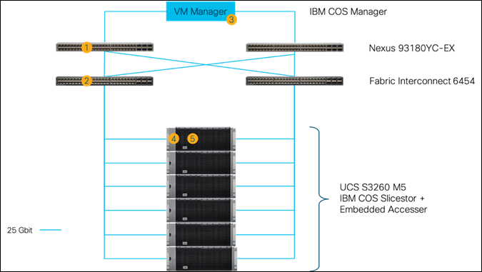
Cisco Nexus 93180YC-EX High Availability Testing
Sequence of Events
1. Connect to Cisco Nexus 93180YC-EX Switch A and make certain running-config is copied to startup-config to make certain no configuration changes are lost during power cycle.
SJC02DMZ-G14-N93180YC-EX-A# copy run start
[########################################] 100%
Copy complete.
2. Initiate load to the cluster by utilizing COSBench.
3. Pull out the power cables from Nexus switch and wait for at least 5 minutes before plugging in the power cables.
![]() The load continues during Cisco Nexus 93180YC-EX reboot process.
The load continues during Cisco Nexus 93180YC-EX reboot process.
Aside from loss of response from Nexus 93180YC-EX switch, the IBM COS environment remained functional, load continued at constant rate, and redundancy was reestablished upon Switch A completing the reboot process.
Cisco UCS Fabric Interconnect 6454 High Availability Testing
Sequence of Events
1. Connect to Cisco UCS Manager and verify that both Fabric Interconnects and all nodes are in a known good working condition.
2. Initiate load to the cluster by utilizing COSBench.
3. Initiate reboot of Fabric Interconnect B where the client interface for IBM COS is located. Establish a secure shell session to Fabric Interconnect B and enter the following commands.
connect local-mgmt
reboot
4. The Fabric Interconnect can take as long as 10 minutes to completely initialize after a reboot. Wait the entire amount of time for this process to complete.
The graph below is a snapshot from COSBench. At the first vertical red line is where Fabric Interconnect B (primary) was rebooted. A slight loss in throughput was observed that could be within the noise of run-to-run variation. The total workload took place over the course of 15 minutes with ample time for Fabric Interconnect B to properly return to a known good state at the second vertical red line.
![]()
![]()
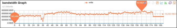
IBM COS Manager VM Failure Testing
Sequence of Events
1. Connect to Cisco UCS Manager and verify that both Fabric Interconnects and all nodes are in a known good working condition.
2. Initiate load to the cluster by utilizing COSBench.
3. Reboot Manager via the OS and wait for at least 5 minutes.
The graph below is a snapshot from COSBench. At the vertical first red line is where the Manager VM was rebooted. There was no drop at all, and the overall write speed remained consistent. At the vertical second line is where the Manager VM was up and running again.
![]()
![]()

Cisco UCS S3260 M5 Disk Failure Testing
Sequence of Events
1. Connect to Cisco UCS Manager and verify that both Fabric Interconnects and all nodes are in a known good working condition.
2. Initiate load to the cluster by utilizing COSBench.
3. Pull out one of 10 TB disks of slicestor1 and wait for at least 10 minutes.
The graph below is a snapshot from COSBench. At the vertical first red line is where Disk 1 was pulled. There was only a minimal drop at all and the overall write speed remained consistent. At the vertical second line is where disk was plugged in again. Overall there was only a very minimal drop in write performance.
![]()
![]()
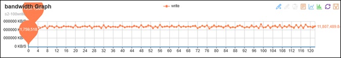
Cisco UCS S3260 M5 Node Failure Testing
Sequence of Events
1. Connect to Cisco UCS Manager and verify that both Fabric Interconnects and all nodes are in a known good working condition.
2. Initiate load to the cluster by utilizing COSBench.
3. Reboot slicestor1.
The graph below is a snapshot from COSBench. At the first vertical red line is where slicestor1 was rebooted. No loss in throughput was observed. At the second red line the reboot of slicestor1 was finished and workload returned to a normal state. The total workload took place over the course of 15 minutes with ample time for slicestor1 to properly return to a known good state.
![]()
![]()
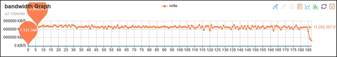
IBM COS Performance Testing
Performance was evaluated on IBM COS running on Cisco S3260 M5 UCS hardware. The goal of the performance testing was to evaluate peak object performance under ideal conditions. S3 performance testing was conducted with COSBench, the standard cloud object storage benchmark. Four physical Cisco UCS servers with overall 18 virtual clients were used as COSBench drivers to generate the object workload. The following picture show the setup of the testing.
Figure 74 COSBench Testing Setup
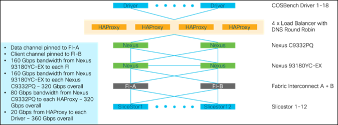
The performance test with COSBench was conducted with the following variables:
· Read and write test
· Object sizes 4 KB, 64 KB, 512 KB, 1 MB, 4 MB, 10 MB, and 100 MB
· 672 workers
During testing we made sure that there is no caching involved and all reads came from disk and not memory.
As expected, the writes for an Object Storage solution become better with bigger object sizes. The below chart shows a peak maximum of ~13 GB/s for writes, which translates to 38 MB/s/disk.
Figure 75 COSBench Write Performance Results
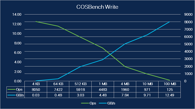
The full table results for writes are shown below. The performance numbers were achieved with 672 workers. As a rule of thumb 2 workers per backend disk should be used.
Table 14 COSBench Write Performance Results
| Object Size |
Throughput in GB/s |
Latency in ms |
Workers |
Ops |
| 4 KB |
0.03 |
85 |
672 |
8050 |
| 64 KB |
0.48 |
92 |
672 |
7422 |
| 512 KB |
3.03 |
101 |
672 |
5918 |
| 1 MB |
4.48 |
134 |
672 |
4483 |
| 4 MB |
7.84 |
304 |
672 |
1960 |
| 10 MB |
9.71 |
613 |
672 |
971 |
| 100 MB |
12.49 |
4701 |
672 |
125 |
For reading, we saw different results. The reads were lower than writes because of the Embedded Accesser configuration, which impacts the performance. The maximum peak for reads was about ~7 GB/s, which translates into ~22 MB/s/disk.
Figure 76 COSBench Read Performance Results
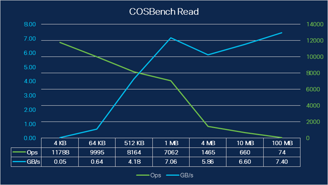
The full table results for reads are shown below.
Table 15 COSBench Read Performance Results
| Object Size |
Throughput in GB/s |
Latency in ms |
Workers |
Ops |
| 4 KB |
0.05 |
39 |
672 |
11788 |
| 64 KB |
0.64 |
50 |
672 |
9995 |
| 512 KB |
4.18 |
62 |
672 |
8164 |
| 1 MB |
7.06 |
72 |
672 |
7062 |
| 4 MB |
5.86 |
404 |
672 |
1465 |
| 10 MB |
6.60 |
878 |
672 |
660 |
| 100 MB |
7.40 |
6606 |
672 |
74 |
During our testing we recognized a failed disk drive for slicestor8. A helpful procedure for working with failed drives is described below.
Working with Failed Drives
A message was logged in the event console:
Figure 77 Failed Disk Drive for slicestor8
![]()
Before replacing the drive, try resuming the drive by following these steps:
1. Click the specific Slicestor node.
2. The drive marked Diagnostic is marked yellow. Click the drive and then click Resume.
Figure 78 Resume Process Starts
![]()
The Slicestor node then tries to bring the disk drive back online.
Figure 79 Resumed Disk Drive for slicestor8
![]()
Object storage is an increasingly popular form of distributing data in a scale-out system. The entry size sinks to more and more smaller units. IBM with IBM COS is leading the pack with its technology when it comes to storing data as an object with high availability and reliability on all kind of solutions.
The solution in this CVD provides customers and partners with everything necessary to store object data easily and securely. Cisco's leading technology of centralized management and advanced networking technology helps to easily deploy, manage and operate the IBM COS solution with Embedded Accessor in Standard Dispersal Mode.
Oliver Walsdorf, Technical Marketing Engineer for Software Defined Storage, Computer Systems Product Group, Cisco Systems, Inc.
Oliver has more than 20 years of storage experience, working in different roles at different storage vendors, and is now an expert for software-defined storage at Cisco. For the past four years Oliver was focused on developing storage solutions at Cisco. He now works on IBM COS, develops Co-Solutions with IBM for the overall storage market and published several Cisco documents. With his focus on SDS he drives the overall attention in the market for new technologies. In his leisure time, Oliver enjoys hiking with his dog and motorcycling.
Acknowledgements
For their support and contribution to the design, validation, and creation of this Cisco Validated Design, we would like to acknowledge the following for their significant contribution and expertise that resulted in developing this document:
· Chris O’Brien, Cisco Systems, Inc.
· Jawwad Memon, Cisco Systems, Inc.
· Paniraja Koppa, Cisco Systems, Inc.
· JT Wood, IBM
· Dashang Vaidya, IBM
[1] Configuration according to http://www.redbooks.ibm.com/redbooks/pdfs/sg248439.pdf page 62.
[2] When creating active-backup bonding under ClevOS, ClevOS takes the first client NIC and the appropriate MAC address to build the bond. The above configuration makes sure that the client traffic goes through FI-B.
[3] The network speed is shown as 40 Gbps but the true network speed is 25 Gbps.