FlexPod Datacenter with Red Hat OpenShift with Intel CPUs M.2 Boot Manual Config Deployment Guide
Available Languages
Bias-Free Language
The documentation set for this product strives to use bias-free language. For the purposes of this documentation set, bias-free is defined as language that does not imply discrimination based on age, disability, gender, racial identity, ethnic identity, sexual orientation, socioeconomic status, and intersectionality. Exceptions may be present in the documentation due to language that is hardcoded in the user interfaces of the product software, language used based on RFP documentation, or language that is used by a referenced third-party product. Learn more about how Cisco is using Inclusive Language.
- US/Canada 800-553-2447
- Worldwide Support Phone Numbers
- All Tools
 Feedback
 Feedback


In partnership with:

About the Cisco Validated Design Program
The Cisco Validated Design (CVD) program consists of systems and solutions designed, tested, and documented to facilitate faster, more reliable, and more predictable customer deployments. For more information, go to: http://www.cisco.com/go/designzone.
The FlexPod Datacenter solution is a validated design for deploying Cisco and NetApp technologies and products to build shared private and public cloud infrastructure. Cisco and NetApp have partnered to deliver a series of FlexPod solutions that enable strategic data center platforms. The success of the FlexPod solution is driven through its ability to evolve and incorporate both technology and product innovations in the areas of management, compute, storage, and networking. This document explains the deployment details of Red Hat OpenShift 4.20 on FlexPod Bare Metal Infrastructure with Intel CPUs. Some of the key advantages of FlexPod Datacenter with Red Hat OpenShift Bare Metal are:
● Consistent Configuration: having a standard method for deploying Red Hat OpenShift on FlexPod Bare Metal infrastructure provides a consistent platform to run containers and virtualized workloads including CPU and GPU accelerated AI/ML workloads, software and models, and OpenShift Virtualization, all side by side on the same infrastructure.
● Cisco Cloud Control Management: Cisco Cloud Control serves as the management and observability gateway for both Cisco Intersight to manage the Cisco UCS compute resources and for Cisco Nexus Dashboard to manage the Cisco Nexus network resources.
● Simpler and programmable infrastructure: the entire underlying infrastructure can be configured using infrastructure as code delivered using Ansible.
● End-to-End 100Gbps Ethernet: utilizing the 5th Generation Cisco UCS VICs and the 6th Generation Cisco UCS 6664 Fabric Interconnects (FIs) to deliver 100Gbps Ethernet from the server through the network to the storage.
● Built for investment protections: design ready for future technologies such as liquid cooling and high-Wattage CPUs; CXL-ready.
In addition to the FlexPod-specific hardware and software innovations, the integration of the Cisco Intersight cloud platform with Red Hat OpenShift and NetApp Active IQ Unified Manager delivers monitoring and orchestration capabilities for different layers (storage and networking) of the FlexPod infrastructure. Implementation of this integration at this point in the deployment process would require Cisco Assist and NetApp Active IQ Unified Manager to be deployed outside of the FlexPod.
For information about the FlexPod design and deployment details, including the configuration of various elements of design and associated best practices, refer to Cisco Validated Designs for FlexPod, here: https://www.cisco.com/c/en/us/solutions/design-zone/data-center-design-guides/flexpod-design-guides.html.
Solution Overview
This chapter contains the following:
● Audience
The intended audience of this document includes but is not limited to IT architects, sales engineers, field consultants, professional services, IT managers, partner engineering, and customers who want to take advantage of an infrastructure built to deliver IT efficiency and enable IT innovation.
This document provides deployment guidance around bringing up the FlexPod Datacenter with Red Hat OpenShift on Bare Metal infrastructure. This configuration is built as a tenant on top of FlexPod Base and assumes FlexPod Base has already been configured. This document introduces various design elements and explains various considerations and best practices for a successful deployment.
The following design elements distinguish this version of FlexPod from previous models:
● Use of Cisco Cloud Control as a gateway to both Cisco Intersight and Cisco Nexus Dashboard.
● Configuration of Red Hat OpenShift Bare Metal as a tenant on top of FlexPod Base. This document is an example of a FlexPod tenant on top of FlexPod Base that aligns with the tenant defined in FlexPod Zero Trust Framework Design Guide.
● Configuration of a platform that will support both Containerized Applications, such as AI applications and Virtual Machines on the same platform.
● Integration of Isovalent Cilium in the installation phase in the Red Hat Assisted Installer to replace Kubernetes Open Virtual Network (OVN) core networking.
● Introduction of the Cisco Intersight Plugin for Red Hat OpenShift to bridge the gap between your applications and physical Cisco UCS infrastructure by bringing unified hardware management directly into the Red Hat web console.
● Introduction and use of Cisco UCS M8 servers with Intel CPUs to validate OpenShift.
● Introduction and use of the Cisco UCS X580p PCIe 5 4-GPU Node along with the Cisco UCS X9516 X-Fabric modules to support NVIDIA RTX PRO 4500, NVIDIA RTX PRO 6000, NVIDIA H200 NVL, and NVIDIA L40S GPUs in the Cisco UCS X9508 chassis.
● Use of Cisco Nexus Dashboard to configure and monitor the Cisco NX-OS based switching.
Deployment Hardware and Software
This chapter contains the following:
The FlexPod Datacenter with Cisco UCS and Cisco Intersight meets the following general design requirements:
● Resilient design across all layers of the infrastructure with no single point of failure
● Scalable design with the flexibility to add compute capacity, storage, or network bandwidth as needed
● Modular design that can be replicated to expand and grow as the needs of the business grow
● Flexible design that can support different supported models of various components with ease
● Simplified design with the ability to integrate and automate with external automation tools
● Cloud-enabled design which can be configured, managed, and orchestrated from the cloud using GUI or APIs
To deliver a solution which meets all these design requirements, various solution components are connected and configured as explained in the following sections.
The FlexPod Datacenter with Red Hat OpenShift on Bare Metal infrastructure configuration is built using the following hardware components:
● Cisco UCS X9508 Chassis with three Cisco UCS X210c M8 Compute Nodes with Intel Xeon 6 CPUs and 1 Cisco UCS X580p PCIe Node containing 2 NVIDIA H200 NVL GPUs and 2 NVIDIA L40S GPUs
● One Cisco UCS C240 M8 EDSFF E3.S Rack Server with Intel Xeon 6 CPUs and 1 L40S GPU attached to the FIs
● Sixth-generation Cisco UCS 6664 Fabric Interconnects to support 100GbE and 64GbFC connectivity from various components
● High-speed Cisco NX-OS-based Nexus 9324C-SE1U Smart Switches to support 100GE connectivity
● NetApp AFF A90 end-to-end NVMe storage with 100G Ethernet connectivity
The software components of this solution consist of:
● Cisco Nexus Dashboard to configure and monitor the Cisco Nexus switching fabric
● Cisco Intersight SaaS platform to deploy, maintain, and support Cisco UCS servers and the FlexPod components
● Cisco Intersight Assist Virtual Appliance to help connect NetApp ONTAP with Cisco Intersight
● NetApp Active IQ Unified Manager to monitor and manage the storage and for NetApp ONTAP integration with Cisco Intersight
● Red Hat OpenShift which provides a platform for both containers and VMs
● NetApp Trident to provide persistent storage for containers and VMs
FlexPod Datacenter with M.2-booted Red Hat OpenShift on Bare Metal Infrastructure Topology
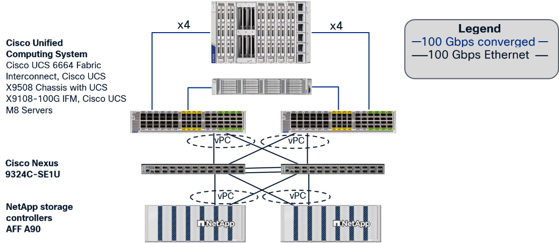
Figure 1 shows various hardware components and the network connections for this IP-based FlexPod design.
The reference hardware configuration includes:
● Two Cisco Nexus 9324C-SE1U switches in Cisco NX-OS mode and configured by Cisco Nexus Dashboard provide the Ethernet switching fabric. Other Cisco Nexus Switches are also supported.
● Two Cisco UCS 6664 Fabric Interconnects (FIs) provide chassis connectivity via 100G Intelligent Fabric Modules (IFMs) in the chassis and rack mount connectivity. At least two 100 Gigabit Ethernet ports from each FI, configured as a Port-Channel, are connected to each Nexus 9324C-SE1U switch. 25 Gigabit Ethernet connectivity is also supported. Other versions of the Cisco UCS FI are also supported.
● One Cisco UCS X9508 Chassis contains 3 Cisco UCS X210c M8 servers and 1 Cisco UCS X580p PCIe Node with 2 NVIDIA H200 NVL GPUs and 2 NVIDIA L40S GPUs. Other configurations of servers with and without GPUs are also supported.
● One Cisco UCS C240 M8 EDSFF E3.S Rack Server with 1 NVIDIA L40S GPU.
● One NetApp AFF A90 HA pair connects to the Cisco Nexus 9324C-SE1U Switches using two 100 GE ports from each controller configured as a Port-Channel. 25 Gigabit Ethernet connectivity is also supported as well as other NetApp AFF, ASA, and FAS storage controllers.
Red Hat OpenShift on Bare Metal Server Configuration
A simple Red Hat OpenShift cluster consists of at least five servers – 3 Control-Plane Nodes and 2 or more Worker Nodes where applications and VMs are run. In this lab validation 3 combination Control-Plane and Worker Nodes and 1 Worker Node were utilized. All servers were configured with 1TB RAM.
Each Node was booted from M.2 drives. iSCSI SAN Boot was considered for this document, but the Red Hat OpenShift Assisted Installer’s Add Host capability cannot currently be used to successfully add an iSCSI-booted host to a cluster or to reinstall Red Hat CoreOS on an existing iSCSI-booted host. An iSCSI-booted cluster can be successfully installed, but the Add Host capability is considered critical for a production system. From a networking perspective, all nodes were configured with a single vNIC with UCS Fabric Failover in the Bare Metal or Management VLAN. Each node had two additional vNICs with the iSCSI A and B VLANs designated as native VLANs on the respective interfaces. The two vNICs also included NVMe-TCP A and B VLANs as allowed VLANs assigned, allowing tagged VLAN interfaces for NVMe-TCP. Finally, each node had two additional vNICs configured as an XOR bond with the OpenShift NFS VLAN configured as native to provide NFS persistent storage. Additionally, this bond had allowed VLANs configured for the OpenShift Virtualization Live Migration network and for all VM networks.
VLAN Configuration
Table 1 lists VLANs configured for setting up the FlexPod environment along with their usage.
| VLAN ID |
Name |
Usage |
IP Subnet used in this deployment |
| 2* |
Native-VLAN |
Use VLAN 2 as native VLAN instead of default VLAN (1) |
|
| 1020* |
OOB-MGMT-VLAN |
Out-of-band management VLAN to connect management ports for various devices |
10.102.0.0/24; GW: 10.102.0.254 |
| 1022 |
OCP-BareMetal-MGMT |
Routable OpenShift Bare Metal VLAN used for OpenShift cluster and node management and for S3 Object Storage |
10.102.2.0/24; GW: 10.102.2.1 |
| 1024 |
OCP-VM-Net |
Routable with DCHP OpenShift VLAN for VMs |
10.102.4.0/24; GW: 10.102.4.1 |
| 3002 |
OCP-Live-Migration |
Used for OpenShift Virtualization Live Migration |
192.168.2.0/24 |
| 3012 |
OCP-Infra-iSCSI-A |
Used for OpenShift iSCSI Persistent Storage with DHCP |
192.168.12.0/24 |
| 3022 |
OCP-Infra-iSCSI-B |
Used for OpenShift iSCSI Persistent Storage with DHCP |
192.168.22.0/24 |
| 3032 |
OCP-Infra-NVMe-TCP-A |
Used for OpenShift NVMe-TCP Persistent Storage with DHCP |
192.168.32.0/24 |
| 3042 |
OCP-Infra-NVMe-TCP-B |
Used for OpenShift NVMe-TCP Persistent Storage with DHCP |
192.168.42.0/24 |
| 3052 |
OCP-Infra-NFS |
Used for OpenShift NFS RWX Persistent Storage with DHCP |
192.168.52.0/24 |
Note: *VLAN configured in FlexPod Base.
Note: S3 object storage was also used in this environment but requires a routable subnet. To avoid having two default gateways on the OpenShift nodes, S3 was placed on the OCP-BareMetal-MGMT subnet and VLAN. A separate VLAN and subnet were not defined for S3.
Table 2 lists the VMs or bare metal servers necessary for deployment as outlined in this document.
| Virtual Machine Description |
VLAN |
IP Address |
Comments |
| OCP AD1 |
1022 |
10.102.2.249 |
Hosted on pre-existing management infrastructure within the FlexPod |
| OCP AD2 |
1022 |
10.102.2.250 |
Hosted on pre-existing management infrastructure within the FlexPod |
| OCP Installer |
1022 |
10.102.2.10 |
Hosted on pre-existing management infrastructure within the FlexPod |
| NetApp Active IQ Unified Manager |
1021 |
10.102.1.97 |
Hosted on pre-existing management infrastructure within the FlexPod |
| Cisco Intersight Assist Virtual Appliance |
1021 |
10.102.1.96 |
Hosted on pre-existing management infrastructure within the FlexPod |
Table 3 lists the software revisions for various components of the solution.
| Layer |
Device |
Image Bundle |
Comments |
| Compute |
Cisco UCS Fabric Interconnect 6664 |
6.0(2.260067) |
|
| Cisco UCS X210c M8 |
6.0(2.260143) |
|
|
| Cisco UCS C240 M8 EDSFF E3.S |
6.0(2.260143) |
|
|
| Cisco UCS Chassis Firmware |
6.0(2.260143) |
|
|
| Cisco UCS PCIe Node Firmware |
6.0(2.260143) |
|
|
| Network |
Cisco Nexus Dashboard |
4.2.1 |
|
|
|
Cisco Nexus 9324C-SE1U NX-OS |
10.6(3)F |
|
| Storage |
NetApp AFF A90 |
ONTAP 9.19.1 |
Latest patch release |
| Software |
Red Hat OpenShift |
4.20 |
|
| NetApp Trident |
26.06.1 |
|
|
| NetApp DataOps Toolkit |
3.1.0 |
|
|
| Cisco Intersight Assist Virtual Appliance |
1.1.7-0.b |
|
|
| NetApp Active IQ Unified Manager |
9.18P3 |
|
|
| NVIDIA GPU Driver |
595.91.07 |
|
The information in this section is provided as a reference for cabling the physical equipment in a FlexPod environment. To simplify cabling requirements, a cabling diagram was used.
The cabling diagram in this section contains the details for the prescribed and supported configuration of the NetApp AFF A90 running NetApp ONTAP 9.19.1.
Note: For any modifications of this prescribed architecture, consult the NetApp Interoperability Matrix Tool (IMT).
Note: This document assumes that out-of-band management ports are plugged into an existing management infrastructure at the deployment site. These interfaces will be used in various configuration steps.
Note: Be sure to use the cabling directions in this section as a guide.
The NetApp storage controller and disk shelves should be connected according to best practices for the specific storage controller and disk shelves. For disk shelf cabling, go to NetApp Support.
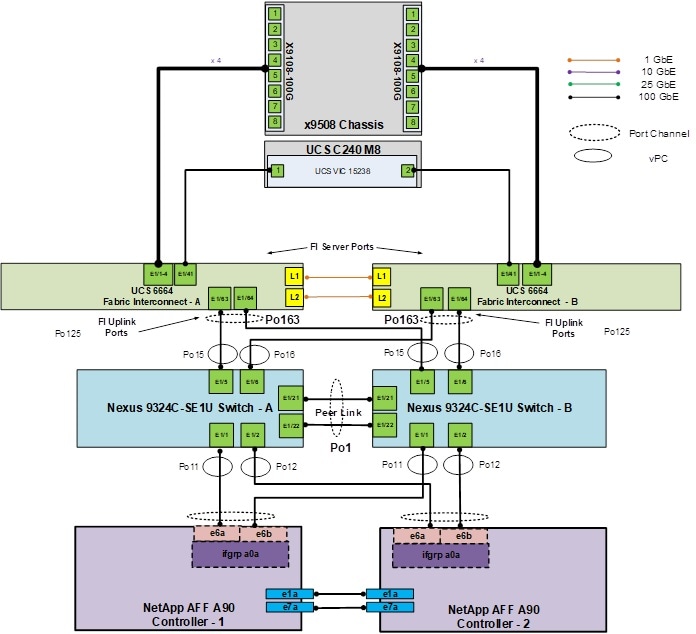
Figure 2 details the cable connections used in the validation lab for the FlexPod topology based on the Cisco UCS 6664 fabric interconnects. Two 100Gb links connect each Cisco UCS Fabric Interconnect to the Cisco Nexus Switches and each NetApp AFF controller to the Cisco Nexus Switches. Additional 1Gb management connections will be needed for one or more out-of-band network switches that sit apart from the FlexPod infrastructure. Each Cisco UCS fabric interconnect and Cisco Nexus switch is connected to the out-of-band network switches, and each AFF controller has a connection to the out-of-band network switches. Layer 3 network connectivity is required between the Out-of-Band (OOB) and In-Band (IB) Management Subnets.
This chapter contains the following:
● Cisco Nexus Dashboard Switch Configuration
This chapter provides a detailed procedure for configuring the Cisco Nexus 9324C-SE1U switches using Nexus Dashboard for use in a FlexPod environment.
Note: The following procedures describe how to configure the Cisco Nexus switches for use in the OpenShift FlexPod environment. This procedure assumes the use of Cisco Nexus 9000 10.6(3)F and Nexus Dashboard 4.2.1.
● The following procedure includes the setup of NTP distribution on the Baremetal-MGMT and VM-Net VLANs.
● This procedure adds the tenant VLANs to the appropriate port-channels.
Follow the physical connectivity guidelines for FlexPod as explained in section FlexPod Cabling.
Cisco Nexus Dashboard Switch Configuration
In this lab configuration, Cisco Nexus Dashboard is used to continue the configuration of the Classic LAN Network Fabric that was started in FlexPod Base to build the OpenShift FlexPod tenant.
Procedure 1. Create and Deploy Tenant Networks in Cisco Nexus Dashboard
Step 1. Either use Cisco Cloud Control to navigate to Nexus Dashboard LAN or navigate to the management IP of any node in the Nexus Dashboard cluster. Log in using the admin account.
Step 2. From the left navigation menu, go to Manage > Fabrics.
Step 3. Click the text link for the FlexPod Fabric to go to the Fabric Overview page. Select the Segmentation and security tab and make sure the Networks tab is selected underneath.
Step 4. Create the OCP-Baremetal-MGMT-VLAN network by using the lower Actions drop-down to choose Create.
Step 5. Fill in the Network name (OCP-Baremetal-MGMT-VLAN). Leave the Network mode set to Layer 3. Use the VRF name drop-down to choose Create VRF.
Note: You will create a FlexPod OpenShift tenant VRF here to separate this OpenShift tenant from other FlexPod tenants.
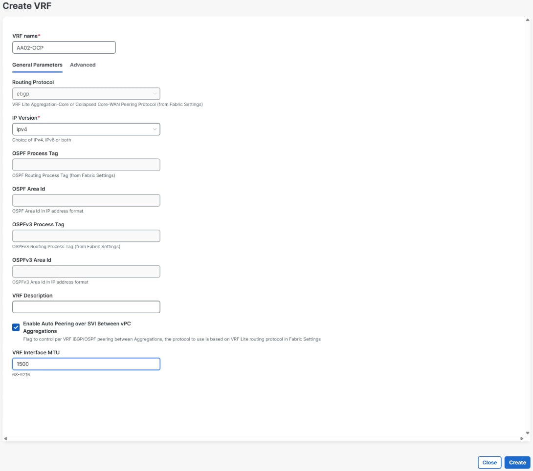
Step 6. Name the VRF (AA02-OCP). For IP Version, select ipv4. Change the VRF Interface MTU to 1500 since this is setting up a management subnet that leaves the pod.
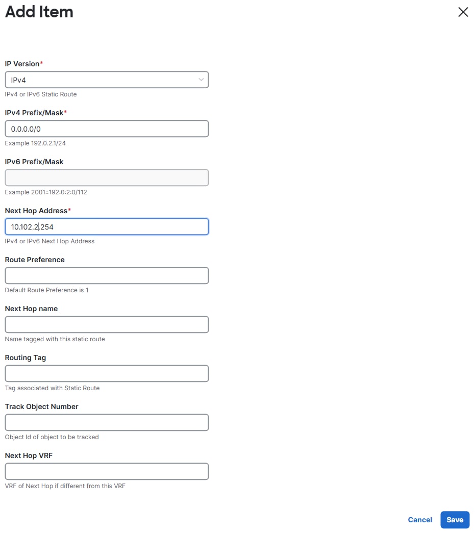
Step 7. Click the Advanced tab. Use the Actions drop-down to select Add to add the default route for the VRF. Enter 0.0.0.0/0 for the IPv4 Prefix/Mask. For the Next Hop Address, enter the Baremetal-MGMT subnet’s default gateway. Click Save.
Step 8. Click Create to create the VRF.
Step 9. Back in the Create network page, enter the VLAN ID (1022). For IPv4 Gateway/NetMask, enter an IP/netmask to be used as the default gateway within the pod (10.102.2.1/24). For Interface IPv4 addr on active, enter the local switch HSRP IP for the active switch (10.102.2.3). For Interface IPv4 addr on standby, enter the local switch HSRP IP for the standby switch (10.102.2.4). For VLAN name, enter the VLAN name that will appear in the switches (AA02-OCP-Baremetal-MGMT). For MTU for L3 interface, enter 1500.
Note: All three IPs entered in this step can be used as NTP server addresses on devices or VMs in this subnet.
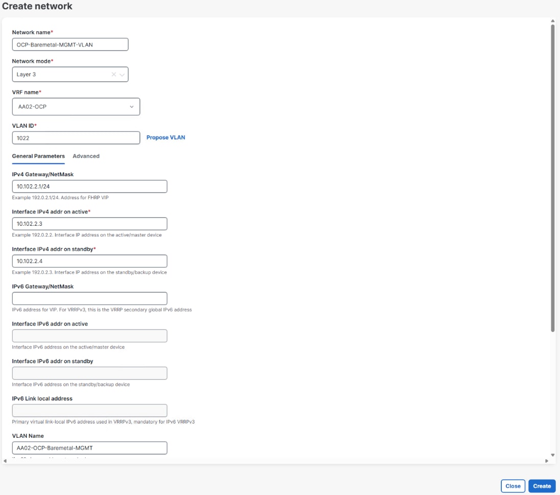
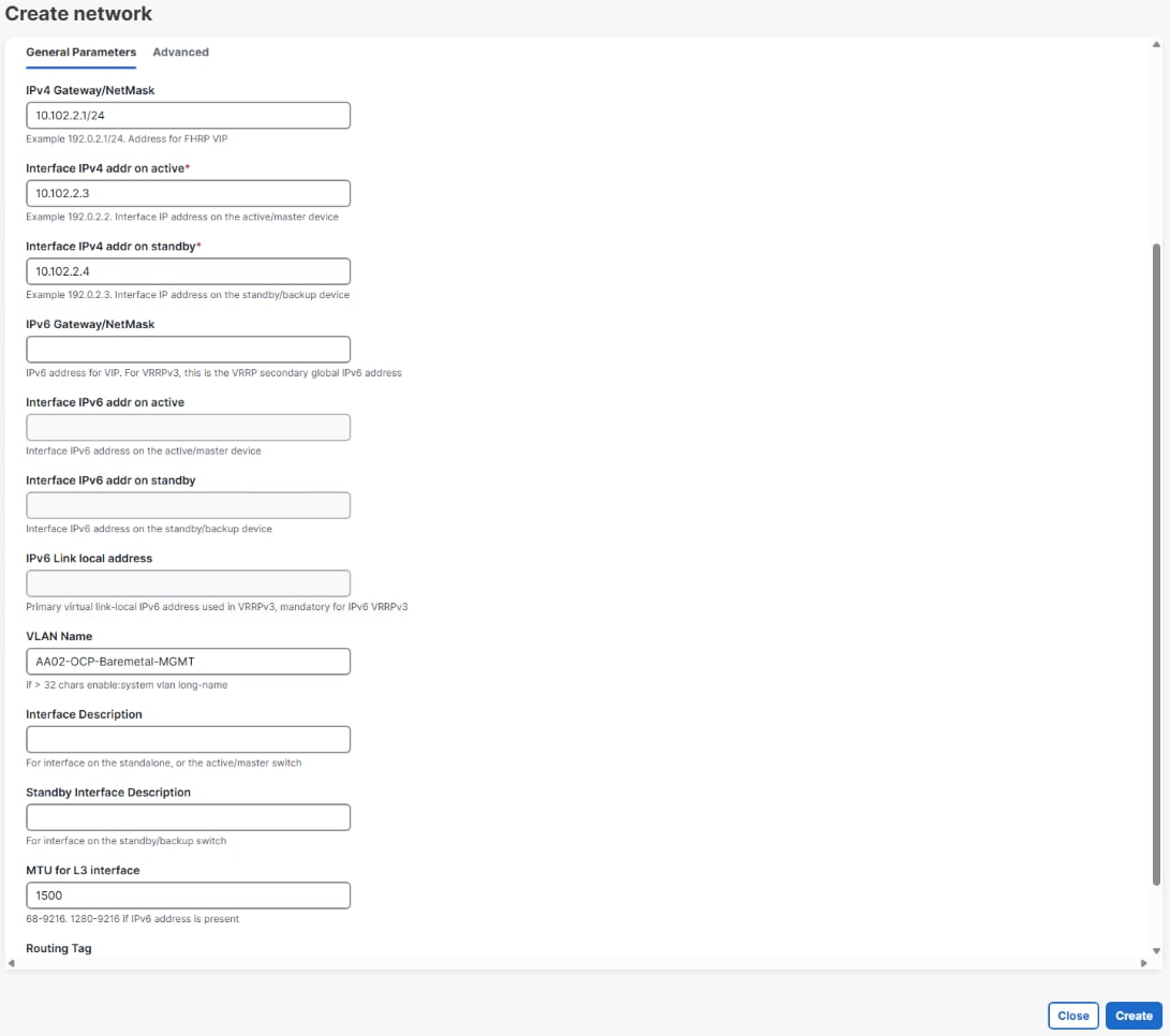
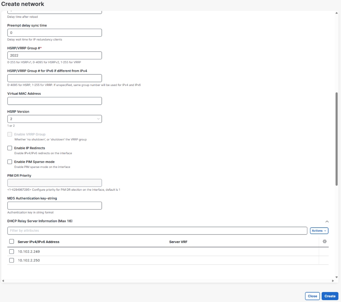
Step 10. Select the Advanced tab. Enter a unique to the VRF HSRP/VRRP Group #.
Note: If this VLAN uplinks out of the pod and connects to an HSRP interface, the HSRP/VRRP Group # must be different than the one that is connected to.
Step 11. To add DHCP forwarding to allow OpenShift Hosts and VMs to get DHCP IPs through the OCP-Baremetal-MGMT subnet (10.102.2.0/24), scroll down to DHCP Relay Server Information. Using the Actions drop-down, choose Add. Enter the IP of your first OCP DHCP server in the OCP-Baremetal-MGMT subnet (10.102.2.249). It is not necessary to enter a Server VRF. Click Save.
Step 12. To add a second DHCP server, using the Actions drop-down, choose Add. Enter the IP of your second OCP DHCP server in the OCP-Baremetal-MGMT subnet (10.102.2.250). It is not necessary to enter a Server VRF. Click Save.
Note: To finish the DHCP Relay configuration, set the default gateway of the DHCP servers to the switch HSRP gateway (10.102.2.1).
Step 13. Click Create to complete the network configuration.
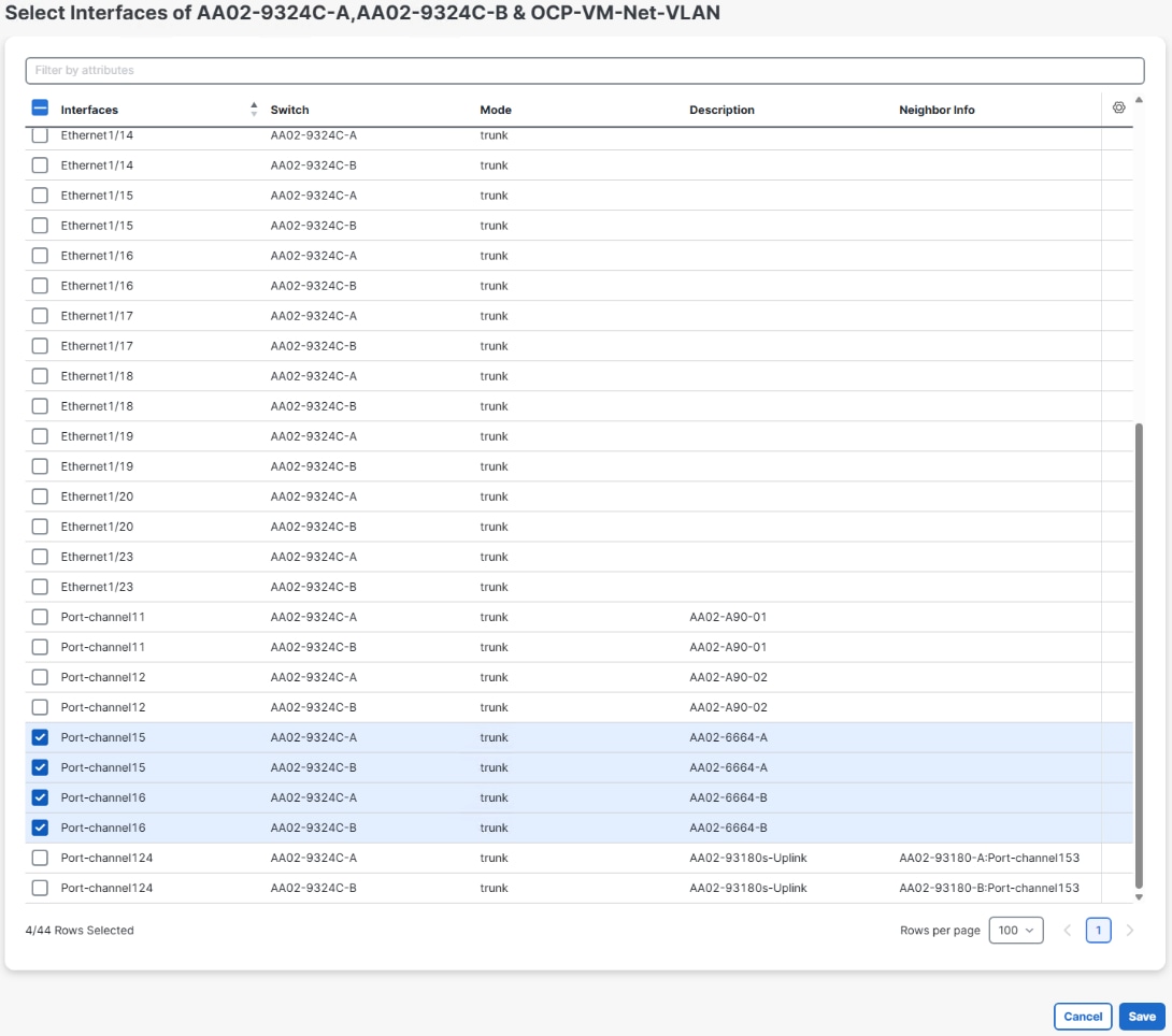
Step 14. Deploy the OCP-Baremetal-MGMT-VLAN network by selecting the checkbox to the left of the network name and using the lower Actions drop-down to select Multi-attach. Select the checkbox to the left of the switch name and click Next. Click Select Interfaces. Scroll down and select all the Port-channel interfaces for storage, UCS FIs, and the Uplinks. Click Save.

Step 15. Click Next.
Step 16. Leave Proceed to full switch deploy (recommended) selected and click Save.
Step 17. Review the Pending config if desired and click Deploy all. When Deployment is completed, click Close.
Step 18. Create the OCP-VM-Net-VLAN network by using the lower Actions drop-down to choose Create.
Step 19. Fill in the Network name (OCP-VM-Net-VLAN). Leave the Network mode set to Layer 3. Use the VRF name drop-down to choose the VRF created above (AA02-OCP).
Step 20. Enter the VLAN ID (1024). For IPv4 Gateway/NetMask, enter an IP/netmask to be used as the default gateway within the pod (10.102.4.1/24). For Interface IPv4 addr on active, enter the local switch HSRP IP for the active switch (10.102.4.3). For Interface IPv4 addr on standby, enter the local switch HSRP IP for the standby switch (10.102.4.4). For VLAN name, enter the VLAN name that will appear in the switches (AA02- OCP-VM-Net). For MTU for L3 interface, enter 1500.
Note: All three IPs entered in this step can be used as NTP server addresses on devices or VMs in this subnet.
Step 21. Select the Advanced tab. Enter a unique to the VRF HSRP/VRRP Group #.
Step 22. To add DHCP forwarding to allow VMs to get DHCP IPs through the OCP-Baremetal-MGMT subnet (10.102.2.0/24), scroll down to DHCP Relay Server Information. Using the Actions drop-down, choose Add. Enter the IP of your first DHCP server in the OCP-Baremetal-MGMT subnet (10.102.2.249). It is not necessary to enter a Server VRF. Click Save.
Step 23. To add a second DHCP server, using the Actions drop-down, choose Add. Enter the IP of your second DHCP server in the OCP-Baremetal-MGMT subnet (10.102.2.250). It is not necessary to enter a Server VRF. Click Save.
Note: To finish the DHCP Relay configuration, in the OCP-Baremetal-MGMT subnet router (10.102.2.254) add a static route to the OCP-VM-Net subnet (10.102.4.0/24) through the OCP-Baremetal-MGMT HSRP gateway (10.102.2.1).
Step 24. Click Create to complete the network configuration.
Step 25. Deploy the OCP-VM-Net-VLAN network by selecting the checkbox to the left of the network name and using the lower Actions drop-down to select Multi-attach. Select the checkbox to the left of the switch name and click Next. Click Select Interfaces. Scroll down and select the Port-channel interfaces only for the FIs. Click Save.
Step 26. Click Next.
Step 27. Leave Proceed to full switch deploy (recommended) selected and click Save.
Step 28. Review the Pending config if desired and click Deploy all. When Deployment is completed, click Close.
Step 29. Create the OCP-Infra-NFS-VLAN network by using the lower Actions drop-down to choose Create.
Step 30. Fill in the Network name (OCP-Infra-NFS-VLAN). Leave the Network mode set to Layer 3. Use the VRF name drop-down to choose the VRF created above (AA02-OCP).
Step 31. Enter the VLAN ID (3052). For IPv4 Gateway/NetMask, enter an IP/netmask to be used as the default gateway within the pod (192.168.52.1/24). For Interface IPv4 addr on active, enter the local switch HSRP IP for the active switch (192.168.52.3). For Interface IPv4 addr on standby, enter the local switch HSRP IP for the standby switch (192.168.52.4). For VLAN name, enter the VLAN name that will appear in the switches (AA02-OCP-Infra-NFS). For MTU for L3 interface, enter 1500.
Step 32. Select the Advanced tab. Enter a unique to the VRF HSRP/VRRP Group #.
Step 33. To add DHCP forwarding to allow VMs to get DHCP IPs through the OCP-Baremetal-MGMT subnet (10.102.2.0/24), scroll down to DHCP Relay Server Information. Using the Actions drop-down, choose Add. Enter the IP of your first DHCP server in the OCP-Baremetal-MGMT subnet (10.102.2.249). It is not necessary to enter a Server VRF. Click Save.
Step 34. To add a second DHCP server, using the Actions drop-down, choose Add. Enter the IP of your second DHCP server in the OCP-Baremetal-MGMT subnet (10.102.2.250). It is not necessary to enter a Server VRF. Click Save.
Step 35. Click Create to complete the network configuration.
Step 36. Deploy the OCP-Infra-NFS-VLAN network by selecting the checkbox to the left of the network name and using the lower Actions drop-down to select Multi-attach. Select the checkbox to the left of the switch name and click Next. Click Select Interfaces. Scroll down and select the Port-channel interfaces for the storage and the FIs. Click Save.
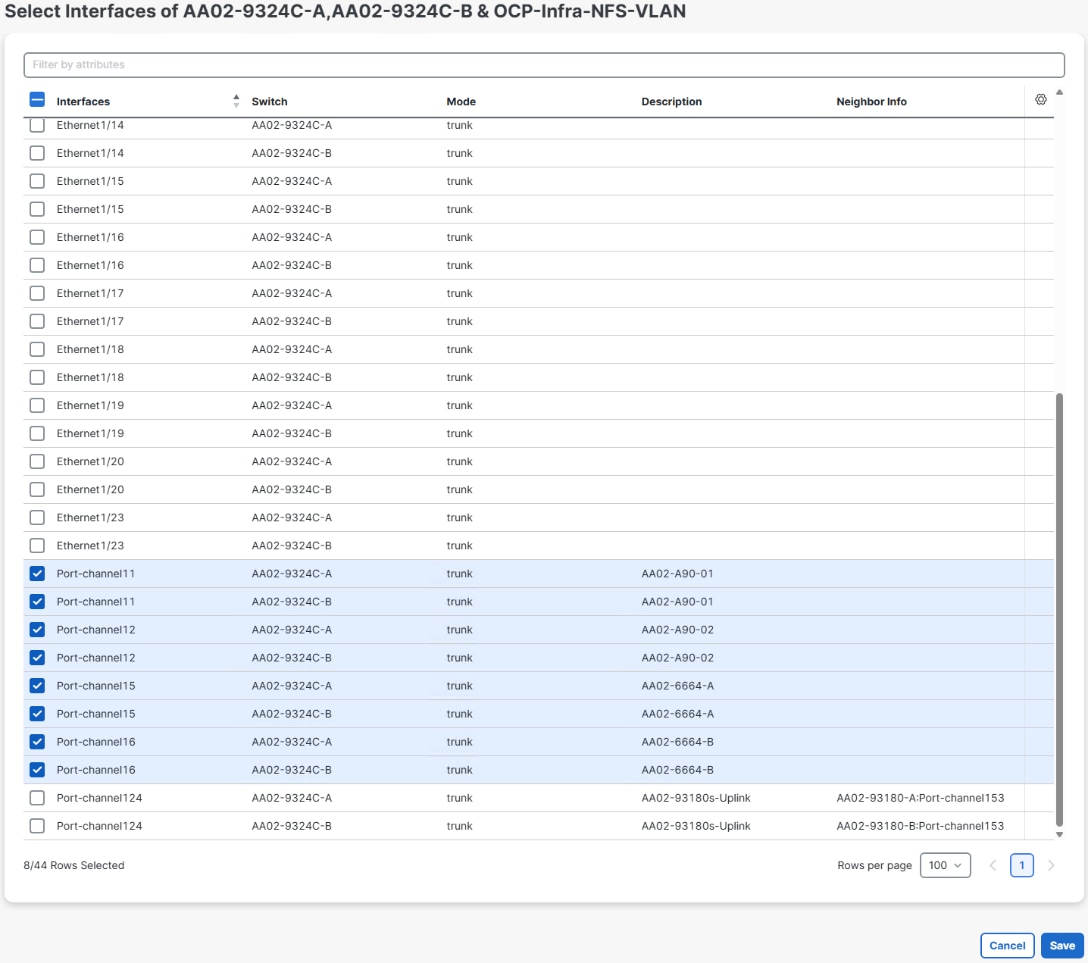
Step 37. Click Next.
Step 38. Leave Proceed to full switch deploy (recommended) selected and click Save.
Step 39. Review the Pending config if desired and click Deploy all. When Deployment is completed, click Close.
Step 40. Repeat steps 29-39 to create and deploy the OCP-Infra-iSCSI-A-VLAN (3012), OCP-Infra-iSCSI-B-VLAN (3022), the OCP-Infra-NVMe-TCP-A-VLAN (3032), and the OCP-Infra-NVMe-TCP-B-VLAN (3042).
Step 41. Create the OCP-Live-Migration-VLAN network by using the lower Actions drop-down to choose Create.
Step 42. Fill in the Network name (OCP-Live-Migration-VLAN). Change the Network mode set to Layer 2 only. Enter the VLAN ID (3002). For VLAN name, enter the VLAN name that will appear in the switches (AA02-OCP-Live-Migration). Click Create.
Step 43. Deploy the OCP-Live-Migration-VLAN network by selecting the checkbox to the left of the network name and using the lower Actions drop-down to select Multi-attach. Select the checkbox to the left of the switch name and click Next. Click Select Interfaces. Scroll down and select the Port-channel interfaces for the FIs only. Click Save.
Step 44. Click Next.
Step 45. Leave Proceed to full switch deploy (recommended) selected and click Save.
Step 46. Review the Pending config if desired and click Deploy all. When Deployment is completed, click Close.
NetApp ONTAP Storage Configuration
This chapter contains the following:
● Configure NetApp ONTAP Storage
● Configure ONTAP S3 Storage Access Using a Dedicated SVM
Configure NetApp ONTAP Storage
This section describes how to configure the NetApp ONTAP Storage for the OpenShift FlexPod Tenant.
Procedure 1. Log into the Cluster
Step 1. Open an SSH connection to either the cluster IP or the host name.
Step 2. Log into the admin user with the password you provided earlier.
Procedure 2. Configure NetApp ONTAP Storage for the OpenShift Tenant
Note: By default, all network ports are included in a separate default broadcast domain. Network ports used for data services (for example, e6a, e6b, and so on) should be removed from their default broadcast domain, and that broadcast domain should be deleted.
Step 1. Delete any Default-N automatically created broadcast domains:
network port broadcast-domain delete -broadcast-domain <Default-N> -ipspace Default
network port broadcast-domain show
Note: Delete the Default broadcast domains with Network ports (Default-1, Default-2, and so on). This does not include Cluster ports and management ports.
Step 2. Create an IPspace for the OpenShift tenant:
network ipspace create -ipspace AA02-OCP
Step 3. Create the OCP-MGMT, OCP-iSCSI-A, OCP-iSCSI-B, OCP-NVMe-TCP-A , OCP-NVMe-TCP-B, and OCP-NFS broadcast domains with appropriate maximum transmission unit (MTU):
network port broadcast-domain create -broadcast-domain OCP-MGMT -mtu 1500 -ipspace AA02-OCP
network port broadcast-domain create -broadcast-domain OCP-iSCSI-A -mtu 9000 -ipspace AA02-OCP
network port broadcast-domain create -broadcast-domain OCP-iSCSI-B -mtu 9000 -ipspace AA02-OCP
network port broadcast-domain create -broadcast-domain OCP-NVMe-TCP-A -mtu 9000 -ipspace AA02-OCP
network port broadcast-domain create -broadcast-domain OCP-NVMe-TCP-B -mtu 9000 -ipspace AA02-OCP
network port broadcast-domain create -broadcast-domain OCP-NFS -mtu 9000 -ipspace AA02-OCP
network port vlan create -node AA02-A90-01 -vlan-name a0a-1022
network port vlan create -node AA02-a90-02 -vlan-name a0a-1022
network port broadcast-domain add-ports -ipspace AA02-OCP -broadcast-domain OCP-MGMT -ports AA02-A90-01:a0a-1022,AA02-A90-02:a0a-1022
Step 5. Create the OpenShift iSCSI VLAN ports and add them to the OpenShift iSCSI broadcast domains:
network port vlan create -node AA02-A90-01 -vlan-name a0a-3012
network port vlan create -node AA02-A90-02 -vlan-name a0a-3012
network port broadcast-domain add-ports -ipspace AA02-OCP -broadcast-domain OCP-iSCSI-A -ports AA02-A90-01:a0a-3012,AA02-A90-02:a0a-3012
network port vlan create -node AA02-A90-01 -vlan-name a0a-3022
network port vlan create -node AA02-A90-02 -vlan-name a0a-3022
network port broadcast-domain add-ports -ipspace AA02-OCP -broadcast-domain OCP-iSCSI-B -ports AA02-A90-01:a0a-3022,AA02-A90-02:a0a-3022
Step 6. Create the OpenShift NVMe-TCP VLAN ports and add them to the OpenShift NVMe-TCP broadcast domains:
network port broadcast-domain add-ports -ipspace AA02-OCP -broadcast-domain OCP-NVMe-TCP-A -ports AA02-A90-01:a0a-3032,AA02-A90-02:a0a-3032
network port vlan create -node AA02-A90-01 -vlan-name a0a-3042
network port vlan create -node AA02-A90-02 -vlan-name a0a-3042
network port broadcast-domain add-ports -ipspace AA02-OCP -broadcast-domain OCP-NVMe-TCP-B -ports AA02-A90-01:a0a-3042,AA02-A90-02:a0a-3042
Step 7. Create the OpenShift NFS VLAN ports and add them to the OpenShift NFS broadcast domain:
network port vlan create -node AA02-A90-01 -vlan-name a0a-3052
network port vlan create -node AA02-A90-02 -vlan-name a0a-3052
network port broadcast-domain add-ports -ipspace AA02-OCP -broadcast-domain OCP-NFS -ports AA02-A90-01:a0a-3052,AA02-A90-02:a0a-3052
Step 8. Verify the creation of VLANs and their addition to corresponding broadcast domains by running the following command:
AA02-A90::> broadcast-domain show -ipspace AA02-OCP
(network port broadcast-domain show)
IPspace Broadcast Update
Name Domain Name MTU Port List Status Details
------- ----------- ------ ----------------------------- --------------
AA02-OCP
OCP-iSCSI-A
9000
AA02-A90-01:a0a-3012 complete
AA02-A90-02:a0a-3012 complete
OCP-iSCSI-B
9000
AA02-A90-01:a0a-3022 complete
AA02-A90-02:a0a-3022 complete
OCP-MGMT 1500
AA02-A90-01:a0a-1022 complete
AA02-A90-02:a0a-1022 complete
OCP-NFS 9000
AA02-A90-01:a0a-3052 complete
AA02-A90-02:a0a-3052 complete
OCP-NVMe-TCP-A
9000
AA02-A90-01:a0a-3032 complete
AA02-A90-02:a0a-3032 complete
OCP-NVMe-TCP-B
9000
AA02-A90-01:a0a-3042 complete
AA02-A90-02:a0a-3042 complete
6 entries were displayed.
Step 9. Create the SVM (Storage Virtual Machine) in the IPspace. Run the vserver create command as shown below:
vserver create -vserver AA02-OCP-SVM -ipspace AA02-OCP -san-multipathing active-active
Note: The SVM must be created in the OpenShift tenant IPspace. An SVM cannot be moved into an IPspace later.
Note: ONTAP 9.19.1 introduces active-active SAN multipathing for AFF systems, including automatic SVM-level LIF failover for improved availability and faster failover. This configuration is supported only on newly created SVMs and cannot be enabled on existing local-active SVMs.
Note: For clusters containing both AFF and FAS systems, NetApp recommends using local-active multipathing consistently across the cluster.
Step 10. Add the required data protocols to the SVM and remove the unused data protocols from the SVM:
vserver add-protocols -vserver AA02-OCP-SVM -protocols nfs,iscsi,nvme
vserver remove-protocols -vserver AA02-OCP-SVM -protocols cifs,fcp,ndmp,s3
Step 11. Add the two data aggregates to the AA02-OCP-SVM aggregate list and enable and run the NFS protocol in the SVM:
vserver modify -vserver AA02-OCP-SVM -aggr-list AA02_A90_01_NVME_SSD_1,AA02_A90_02_NVME_SSD_1
vserver nfs create -vserver AA02-OCP-SVM -udp disabled -v3 enabled -v4.1 enabled -v4.2 enabled
Step 12. Create a Load-Sharing Mirror of the SVM Root Volume. Create a volume to be the load-sharing mirror of the infrastructure SVM root volume only on the node that does not have the Root Volume:
volume show -vserver AA02-OCP-SVM # Identify the aggregate and node where the vserver root volume is located.
volume create -vserver AA02-OCP-SVM -volume AA02_OCP_SVM_root_lsm01 -aggregate AA02_A90_01_NVME_SSD_1 -size 1GB -type DP # Create the mirror volume on the other node
AA02-A90::> volume show -vserver AA02-OCP-SVM Vserver Volume Aggregate State Type Size Available Used%
--------- ------------ ------------ ---------- ---- ---------- ---------- -----
AA02-OCP-SVM
AA02_OCP_SVM_root
AA02_A90_02_NVME_SSD_1
online RW 1GB 972.5MB 0%
AA02-OCP-SVM
AA02_OCP_SVM_root_lsm01
AA02_A90_01_NVME_SSD_1
online DP 1GB 1023MB 0%
2 entries were displayed.
Step 13. Create the 15min interval job schedule:
job schedule interval create -name 15min -minutes 15
Step 14. Create the mirroring relationship by running the snapmirror create command:
snapmirror create -source-path AA02-OCP-SVM:AA02_OCP_SVM_root -destination-path AA02-OCP-SVM:AA02_OCP_SVM_root_lsm01 -type LS -schedule 15min
Step 15. Initialize and verify the mirroring relationship:
snapmirror initialize-ls-set -source-path AA02-OCP-SVM:AA02_OCP_SVM_root
AA02-A90::> snapmirror show -vserver AA02-OCP-SVM
Progress
Source Destination Mirror Relationship Total Last
Path Type Path State Status Progress Healthy Updated
----------- ---- ------------ ------- -------------- --------- ------- --------
AA02-A90://AA02-OCP-SVM/AA02_OCP_SVM_root
LS AA02-A90://AA02-OCP-SVM/AA02_OCP_SVM_root_lsm01
Snapmirrored
Idle - true -
Step 16. Create the iSCSI and NVMe services:
vserver iscsi create -vserver AA02-OCP-SVM -status-admin up
AA02-A90::> vserver iscsi show -vserver AA02-OCP-SVM
Vserver: AA02-OCP-SVM
Target Name: iqn.1992-08.com.netapp:sn.7d3aa9e45fd511f1a537d039eac0d154:vs.10
Target Alias: AA02-OCP-SVM
Administrative Status: up
vserver nvme create -vserver AA02-OCP-SVM -status-admin up
AA02-A90::> vserver nvme show -vserver AA02-OCP-SVM
Vserver Name: AA02-OCP-SVM
Administrative Status: up
Discovery Subsystem NQN: nqn.1992-08.com.netapp:sn.7d3aa9e45fd511f1a537d039eac0d154:discovery
Note: Make sure required licenses are installed for all storage protocols used before creating the services.
Step 17. To create the login banner for the SVM, run the following command:
security login banner modify -vserver AA02-OCP-SVM -message "This AA02-OCP-SVM is reserved for authorized users only!"
Step 18. Create a new rule for the AA02-OCP-SVM NFS subnet in the default export policy and assign the policy to the SVM’s root volume:
vserver export-policy rule create -vserver AA02-OCP-SVM -policyname default -ruleindex 1 -protocol nfs -clientmatch 192.168.52.0/24 -rorule sys -rwrule sys -superuser sys -allow-suid true
volume modify -vserver AA02-OCP-SVM -volume AA02_OCP_SVM_root -policy default
Step 19. Create and enable the audit log in the SVM:
volume create -vserver AA02-OCP-SVM -volume AA02_OCP_SVM_audit_log -aggregate AA02_A90_01_NVME_SSD_1 -size 50GB -state online -policy default -junction-path /AA02_OCP_SVM_audit_log -space-guarantee none -percent-snapshot-space 0
snapmirror update-ls-set -source-path AA02-OCP-SVM:AA02_OCP_SVM_root
vserver audit create -vserver AA02-OCP-SVM -destination /AA02_OCP_SVM_audit_log
vserver audit enable -vserver AA02-OCP-SVM
Step 20. Run the following commands to create NFS Logical Interfaces (LIFs):
network interface create -vserver AA02-OCP-SVM -lif nfs-lif-01 -service-policy default-data-files -home-node AA02-A90-01 -home-port a0a-3052 -address 192.168.52.51 -netmask 255.255.255.0 -status-admin up -failover-policy broadcast-domain-wide -auto-revert true
network interface create -vserver AA02-OCP-SVM -lif nfs-lif-02 -service-policy default-data-files -home-node AA02-A90-02 -home-port a0a-3052 -address 192.168.52.52 -netmask 255.255.255.0 -status-admin up -failover-policy broadcast-domain-wide -auto-revert true
Step 21. Run the following commands to create iSCSI LIFs:
network interface create -vserver AA02-OCP-SVM -lif iscsi-lif-01a -service-policy default-data-iscsi -home-node AA02-A90-01 -home-port a0a-3012 -address 192.168.12.51 -netmask 255.255.255.0 -status-admin up
network interface create -vserver AA02-OCP-SVM -lif iscsi-lif-01b -service-policy default-data-iscsi -home-node AA02-A90-01 -home-port a0a-3022 -address 192.168.22.51 -netmask 255.255.255.0 -status-admin up
network interface create -vserver AA02-OCP-SVM -lif iscsi-lif-02a -service-policy default-data-iscsi -home-node AA02-A90-02 -home-port a0a-3012 -address 192.168.12.52 -netmask 255.255.255.0 -status-admin up
network interface create -vserver AA02-OCP-SVM -lif iscsi-lif-02b -service-policy default-data-iscsi -home-node AA02-A90-02 -home-port a0a-3022 -address 192.168.22.52 -netmask 255.255.255.0 -status-admin up
Step 22. Run the following commands to create NVMe-TCP LIFs:
network interface create -vserver AA02-OCP-SVM -lif nvme-tcp-lif-01a -service-policy default-data-nvme-tcp -home-node AA02-A90-01 -home-port a0a-3032 -address 192.168.32.51 -netmask 255.255.255.0 -status-admin up
network interface create -vserver AA02-OCP-SVM -lif nvme-tcp-lif-01b -service-policy default-data-nvme-tcp -home-node AA02-A90-01 -home-port a0a-3042 -address 192.168.42.51 -netmask 255.255.255.0 -status-admin up
network interface create -vserver AA02-OCP-SVM -lif nvme-tcp-lif-02a -service-policy default-data-nvme-tcp -home-node AA02-A90-02 -home-port a0a-3032 -address 192.168.32.52 -netmask 255.255.255.0 -status-admin up
network interface create -vserver AA02-OCP-SVM -lif nvme-tcp-lif-02b -service-policy default-data-nvme-tcp -home-node AA02-A90-02 -home-port a0a-3042 -address 192.168.42.52 -netmask 255.255.255.0 -status-admin up
Step 23. Run the following command to create the SVM management LIF on the node where the SVM root volume is located:
network interface create -vserver AA02-OCP-SVM -lif svm-mgmt -service-policy default-management -home-node AA02-A90-02 -home-port a0a-1022 -address 10.102.2.50 -netmask 255.255.255.0 -status-admin up -failover-policy broadcast-domain-wide -auto-revert true
Step 24. Run the following command to verify LIFs:
AA02-A90::> network interface show -vserver AA02-OCP-SVM
Logical Status Network Current Current Is
Vserver Interface Admin/Oper Address/Mask Node Port Home
----------- ---------- ---------- ------------------ ------------- ------- ----
AA02-OCP-SVM
iscsi-lif-01a
up/up 192.168.12.51/24 AA02-A90-01 a0a-3012
true
iscsi-lif-01b
up/up 192.168.22.51/24 AA02-A90-01 a0a-3022
true
iscsi-lif-02a
up/up 192.168.12.52/24 AA02-A90-02 a0a-3012
true
iscsi-lif-02b
up/up 192.168.22.52/24 AA02-A90-02 a0a-3022
true
nfs-lif-01 up/up 192.168.52.51/24 AA02-A90-01 a0a-3052
true
nfs-lif-02 up/up 192.168.52.52/24 AA02-A90-02 a0a-3052
true
nvme-tcp-lif-01a
up/up 192.168.32.51/24 AA02-A90-01 a0a-3032
true
nvme-tcp-lif-01b
up/up 192.168.42.51/24 AA02-A90-01 a0a-3042
true
nvme-tcp-lif-02a
up/up 192.168.32.52/24 AA02-A90-02 a0a-3032
true
nvme-tcp-lif-02b
up/up 192.168.42.52/24 AA02-A90-02 a0a-3042
true
svm-mgmt up/up 10.102.2.50/24 AA02-A90-02 a0a-1022
true
11 entries were displayed.
Step 25. Create a default route that enables the SVM management interface to reach the outside world:
network route create -vserver AA02-OCP-SVM -destination 0.0.0.0/0 -gateway 10.102.2.1
Step 26. Set a password for the SVM vsadmin user and unlock the user:
security login password -username vsadmin -vserver AA02-OCP-SVM
Enter a new password:
Enter it again:
security login unlock -username vsadmin -vserver AA02-OCP-SVM
Step 27. Add the OpenShift DNS servers to the SVM:
dns create -vserver AA02-OCP-SVM -domains ocp.flexpodb4.cisco.com -name-servers 10.102.2.249,10.102.2.250
Configure ONTAP S3 Storage Access Using a Dedicated SVM
Procedure 1. Create SVM and enable S3 protocol access
Step 1. In NetApp ONTAP System Manager, click Cluster > Storage VMs, click the Add icon.
Step 2. Add storage VM page appears. Provide Storage VM name (AA02-OCP-S3-SVM). Select the appropriate IPspace (AA02-OCP).
Step 3. Under Access protocol section, select Enable S3 checkbox to configure S3 access for the SVM.
Step 4. Enter the S3 server name. Make sure to enter the S3 server name as a Fully Qualified Domain Name (FQDN).
Step 5. TLS is enabled by default (port 443). You can enable HTTP if required.
Step 6. Select the certificate type. Whether you select system-generated certificate or external-CA signed certificate, it will be required for client access.
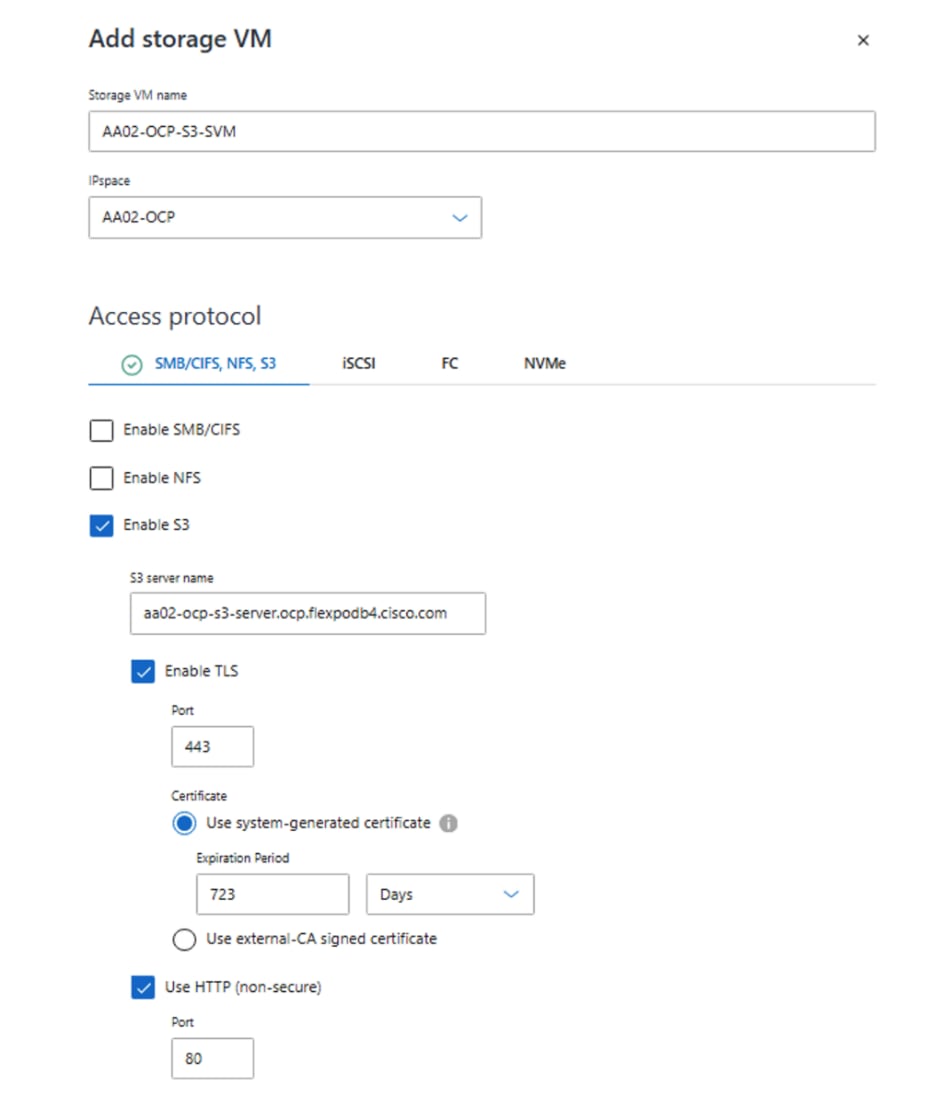
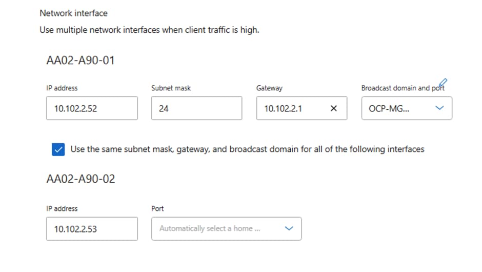
Step 7. Enter the network interfaces. Provide the IP address, subnet mask, gateway, broadcast domain and port details for creating interfaces. Note that here the S3 object storage will be placed on the OCP-BareMetal-MGMT subnet and VLAN.
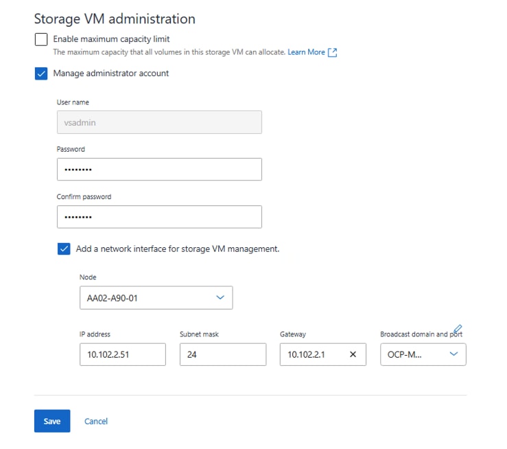
Step 8. Under Storage VM administration section, select the Manage administrator account checkbox. Provide a password for the SVM vsadmin user. Select the Add a network interface for storage VM management checkbox and enter the network interface for SVM management LIF.
Step 9. Click Save. SVM is successfully created with S3 protocol access.
Step 10. Using an ssh session, set auto-revert parameter to true on the S3 SVM LIFs:
AA02-A90::> network interface show -vserver AA02-OCP-S3-SVM -fields auto-revert
vserver lif auto-revert
--------------- ------------------------ -----------
AA02-OCP-S3-SVM lif_AA02-OCP-S3-SVM_2533 false
AA02-OCP-S3-SVM lif_AA02-OCP-S3-SVM_5344 false
AA02-OCP-S3-SVM lif_AA02-OCP-S3-SVM_6905 false
3 entries were displayed.
AA02-A90::> network interface modify -vserver AA02-OCP-S3-SVM -lif lif_AA02-OCP-S3-SVM_* -auto-revert true
3 entries were modified.
Procedure 2. Configure an ONTAP S3 user
The ONTAP S3 object store server is now configured as shown in the following figure. There are two users created by default:
1. root user with UID 0 – no access key or secret key is generated for this user
2. sm_s3_user – both access and secret keys are generated for this user
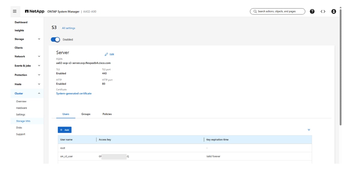
Note: The ONTAP administrator must run the vserver object-store-server user regenerate-keys command to set the access key and secret key for the root user. As a NetApp best practice, do not use this root user. Any client application that uses the access key or secret key of the root user has full access to all buckets and objects in the object store.
Step 1. You can choose to utilize the default user (sm_s3_user) or create a custom ONTAP S3 user by executing following steps:
a. Click Cluster > Storage VMs. Select the storage VM (AA02-OCP-S3-SVM) to which you need to add a user, select Settings and then click the pencil icon under S3.
b. To add a user, click Users > Add.
c. Enter a name for the user. Click Save.
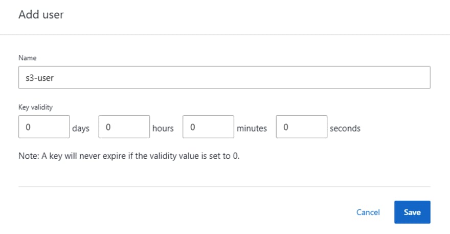
d. The user (s3-user) is created, and an access key and a secret key are generated for the user.
e. Download or save the access key and secret key. These will be required for access from S3 clients.
Note: Beginning with ONTAP 9.14.1, you can specify the retention period of the access keys that get created for the user. You can specify the retention period in days, hours, minutes, or seconds, after which the keys automatically expire. By default, the value is set to 0 that indicates that the key is indefinitely valid.
Note: Beginning with ONTAP 9.19.1, you can also generate or remove a second access key for an S3 user, allowing continued access to S3 resources if the original access key expires.
Procedure 3. Create ONTAP S3 user group to control access to buckets
Step 1. Click Cluster > Storage VMs. Select the storage VM (AA02-OCP-S3-SVM) to which you need to add a group, select Settings and then click the pencil icon under S3.
Step 2. To add a group, select Groups, then click Add.
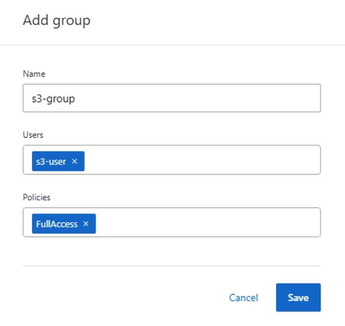
Step 3. Enter a group name and select from a list of users.
Step 4. You can select an existing group policy or add one now, or you can add a policy later. In this configuration, we have used an existing policy (FullAccess).
Step 5. Click Save.
Procedure 4. Create an ONTAP S3 bucket
Step 1. Click Storage > Buckets, then click Add.
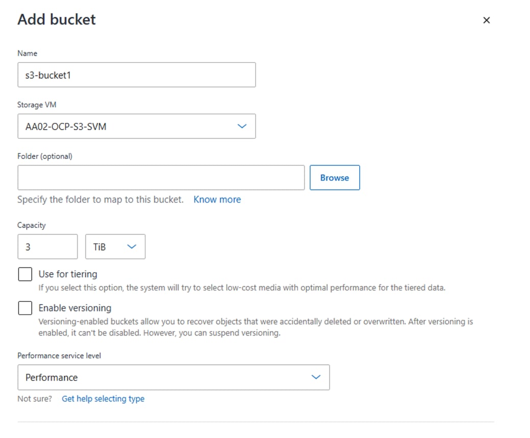
Step 2. Enter a name for the bucket, select the storage VM (AA02-OCP-S3-SVM), and enter the size.
a. If you click Save at this point, a bucket is created with these default settings:
i. No users are granted access to the bucket unless any group policies are already in effect.
ii. A Quality of Service (performance) level that is the highest available for your system.
b. Click Save if you want to create a bucket with these default values.
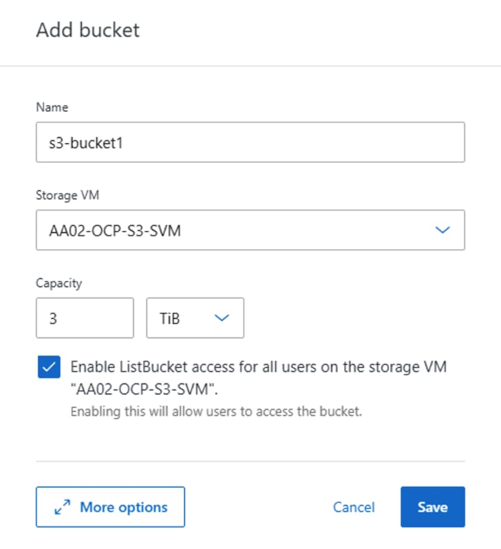
Step 3. Click More Options to configure settings for object locking, user permissions, and performance level when you configure the bucket, or you can modify these settings later.
a. If you intend to use the S3 object store for FabricPool tiering, consider selecting Use for tiering rather than a performance service level. In this validation, we are not using S3 for FabricPool tiering.
b. To enable versioning for your objects for later recovery, select Enable Versioning. In this case, we have not enabled versioning.
c. Performance service level – default value (Performance) is used in this configuration.
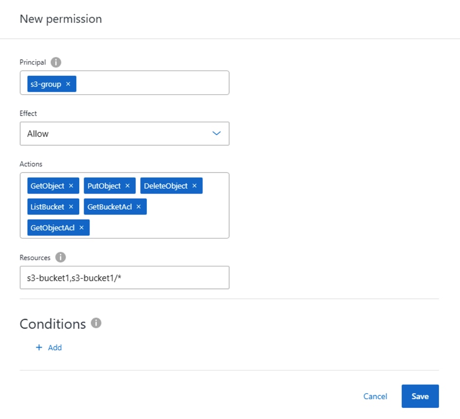
Step 4. Under Permissions section, click Add to add relevant permissions for accessing the bucket. Specify the following parameters:
a. Principal: the user or group to whom access is granted. Here, we selected “s3-group”.
b. Effect: allows or denies access to a user or group. Allow is selected here for “s3-group”.
c. Actions: permissible actions in the bucket for a given user or group. Select as required for validation.
d. Resources: paths and names of objects within the bucket for which access is granted or denied. The defaults bucketname and bucketname/* grant access to all objects in the bucket. In this solution, we used default values for resources (s3-bucket1,s3-bucket1/*)
e. Conditions (optional): expressions that are evaluated when access is attempted. For example, you can specify a list of IP addresses for which access will be allowed or denied. In this case, the field value was empty as no conditions were specified.
Step 5. Click Save.
Step 6. Click Save to create the ONTAP S3 bucket.
Note: In this configuration, we did not enable S3 object locking, but you can enable it if required by the validation.
Note: You can configure protection for the bucket by enabling SnapMirror (ONTAP or cloud) if needed. In this validation, this was not required.
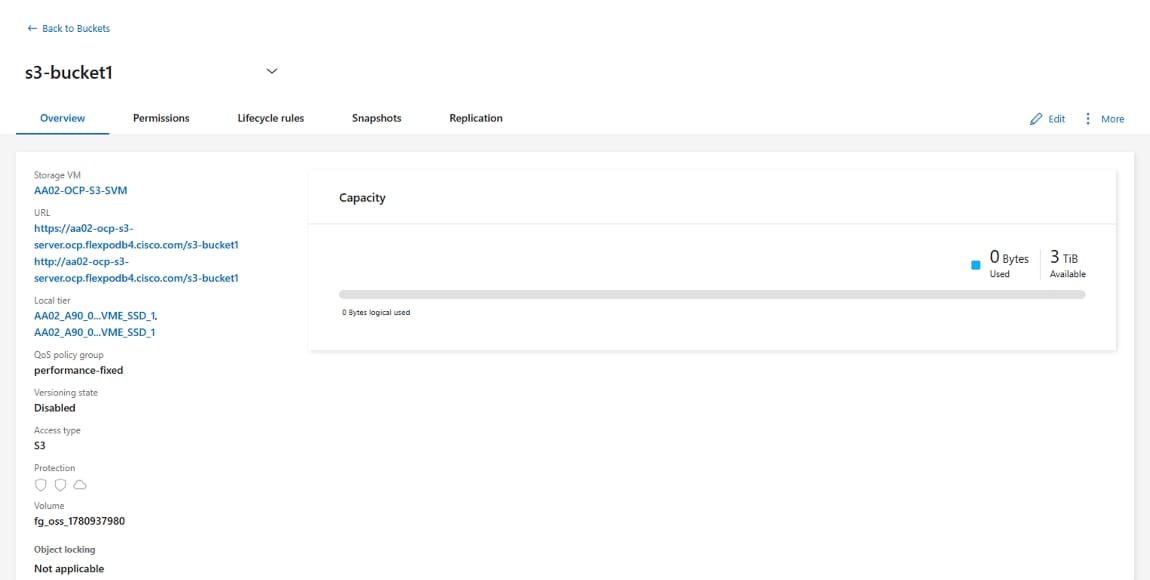
Step 7. ONTAP S3 bucket is successfully created as shown in the following figure. Navigate to Storage > Buckets, select the bucket (s3-bucket1) and click Overview tab to see detailed information about the bucket.
Step 8. On S3 client applications (whether ONTAP S3 or an external third-party application), you can verify access to the newly created S3 bucket. In this solution, we used S3 Browser application to access the bucket as shown in the following figure.
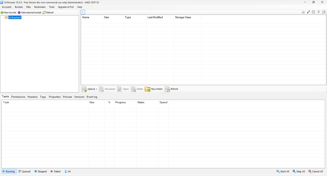
Note: In S3 Browser application, a new account needs to be created first by providing S3 user access key and secret key, and REST endpoint (http://<s3-lif-ip>:80). Once account is added successfully, S3 buckets would be fetched automatically as shown above.
Cisco Cloud Control and Intersight Managed Mode Configuration
This chapter contains the following:
● Set up and Configure Cisco Intersight for the OpenShift Tenant
Cisco Cloud Control is Cisco’s unified operations platform for bringing networking, security, compute, observability, and collaboration into a consistent operational environment. It provides a single experience for viewing inventory, topology, health, alerts, and operational actions across supported Cisco platforms, including Nexus Dashboard and Intersight. Rather than replacing existing product controllers, Cloud Control connects and complements them, enabling cross-domain visibility and workflows from a common interface. Its AI Assistant and AI Canvas capabilities support Cisco’s AgenticOps model, allowing operators and governed AI agents to correlate information across domains, investigate problems, identify root causes, and coordinate remediation while keeping people in control of operational decisions.
The Cisco Intersight platform is a management solution delivered as a service with embedded analytics for Cisco and third-party IT infrastructures. The Cisco Intersight Managed Mode (also referred to as Cisco IMM or Intersight Managed Mode) is an architecture that manages Cisco Unified Computing System (Cisco UCS) fabric interconnect–attached systems through a Redfish-based standard model. Cisco Intersight managed mode standardizes both policy and operation management for Cisco UCS C-Series M8 and Cisco UCS X210c M8 compute nodes used in this deployment guide.
Cisco UCS B-Series M6 and M7 servers, connected and managed through Cisco UCS FIs, are also supported by IMM. For a complete list of supported platforms, go to: https://www.cisco.com/c/en/us/td/docs/unified_computing/Intersight/b_Intersight_Managed_Mode_Configuration_Guide/b_intersight_managed_mode_guide_chapter_01010.html
Set up and Configure Cisco Intersight for the OpenShift Tenant
This section contains the procedures to set up and configure Cisco Intersight for the OpenShift Tenant.
Procedure 1. Set up Cisco Intersight Resource Group
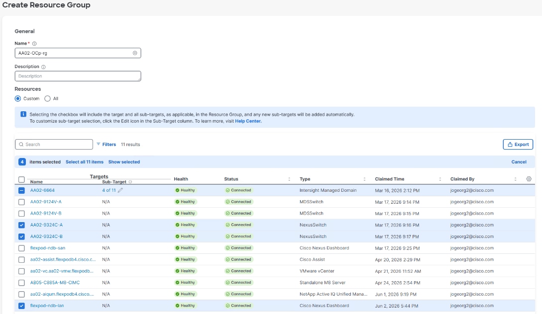
In this procedure, a Cisco Intersight resource group for the Red Hat OpenShift tenant is created where resources such as targets will be logically grouped. In this deployment, a single resource group is created to host all the resources, but you can choose to create multiple resource groups for granular control of the resources.
Step 1. Log into Cisco Cloud Control or Intersight and connect to the account for this FlexPod.
Step 2. Select System > Resource Groups.
Step 3. Click + Create Resource Group in the top-right corner.
Step 4. Provide a name for the Resource Group (for example, AA02-OCP-rg).
Step 5. Under Resources, select Custom.
Step 6. Select all resources that are connected to this OpenShift FlexPod tenant.
Note: If more than one FlexPod tenant is sharing the FIs, a subset of the servers can be assigned to the Resource Group.
Step 7. Click Create.
Procedure 2. Set Up Tenant Intersight Organization
In this procedure, an Intersight organization for the OpenShift tenant is created where all tenant Cisco Intersight Managed Mode configurations including policies are defined. The FlexPod Policy organization will also be modified to share resources with this organization.
Step 1. Select System > Organizations.
Step 2. Click + Create Organization in the top-right corner.
Step 3. Provide a name and description for the organization (for example, AA02-OCP) and click Next.
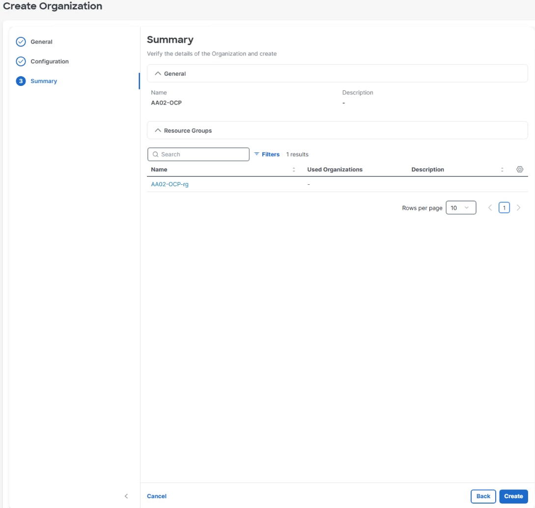
Step 4. Select the Resource Group created in the previous procedure (for example, AA02-OCP-rg) and click Next.
Step 5. Click Create.
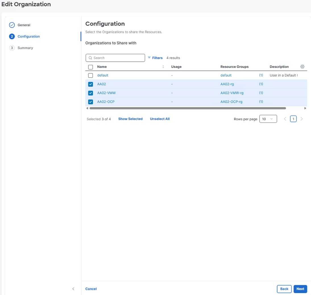
Step 6. Select the radio button to the left of the FlexPod Policy Organization (AA02-Policy). Click the three dots to the right of the Organization and choose Edit.
Step 7. Click Next.
Step 8. Click Show All. Select the checkbox to the left of the OCP (AA02-OCP) Organization. Click Next.
Step 9. Click Save.
Procedure 3. Add OpenShift VLANs to VLAN Policy
Step 1. Select Configure > Templates > UCS Domain Profile Templates.
Step 2. To the right of the UCS Domain Profile Template used for the OpenShift tenant, click … and select Edit.
Step 3. Click Next to go to VLAN & VSAN Configuration.
Step 4. Under VLAN & VSAN Configuration, click the pencil icon to the left of (they are both the same policy) VLAN Policy to Edit the policy.
Step 5. Click Next to go to Policy Details.
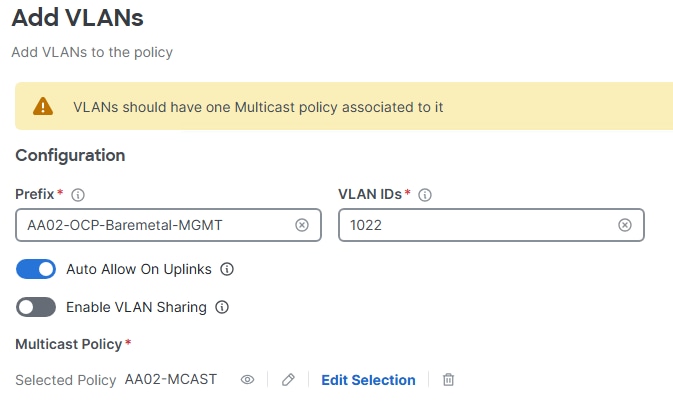
Step 6. To add the Baremetal-MGMT VLAN, click Add VLANs.
Step 7. For the Prefix, enter the VLAN name (AA02-OCP-Baremetal-MGMT). For the VLAN ID, enter the VLAN id (1022). Leave Auto Allow on Uplinks enabled and Enable VLAN Sharing disabled.
Step 8. Under Multicast Policy, click Select Policy and select the already configured Multicast Policy (for example, AA02-MCAST). Click Add to add the VLAN to the policy.
Step 9. Repeat steps 1 – 8 to add all the VLANs in Table 1 to the VLAN Policy.
Step 10. Click Save to save the VLAN Policy.
Step 11. Select Configure > Profiles > UCS Domain Profiles.
Step 12. Click the … to the right of the UCS Domain Profile used for the OpenShift tenant and select Deploy and then Deploy again to deploy the UCS Domain Profile.
Procedure 1. Create IP Pool for In-Band CIMC Access
For CIMC and vKVM access, an IP Pool in the IB-MGMT subnet will be created to allow CIMC and vKVM access within a tenant VLAN and subnet.
Step 1. Select Configure > Pools. On the right, click Create Pool. Click the radio button to the left of IP and click Start.
Step 2. Select the correct organization from the drop-down list (for example, AA02-OCP) and provide a name for the policy (for example, AA02-OCP-Baremetal-MGMT-IP). Enter optional tags and a description. Click Next.
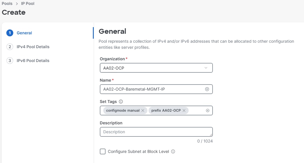
Step 3. Ensure Configure IPv4 Pool is enabled and provide the information to define a unique pool for KVM IP address assignment including an IP Block (added by clicking Add IP Blocks).
Note: You will need the IP addresses of the OpenShift DNS servers.
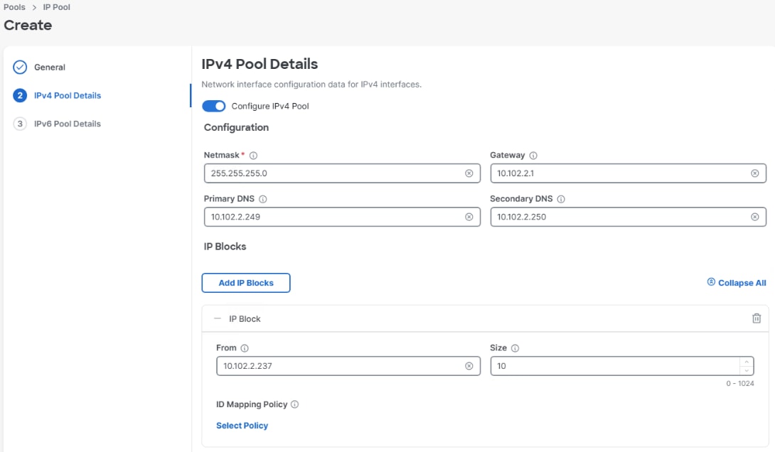
Note: The management IP pool subnet should be accessible from the host that is trying to open the KVM connection. In the example shown here, the hosts trying to open a KVM connection would need to be able to route to the subnet you are using (10.102.2.0/24).
Step 4. Click Next.
Step 5. Deselect Configure IPv6 Pool.
Step 6. Click Create to finish configuring the IP address pool.
Procedure 2. Create MAC Address Pools for Fabric A and B
A FlexPod with three tenants is being built. All resources (MAC addresses, WWNNs, WWPNs, and so on) are being divided into three groups. If looking at the last octet which contains 255 addresses, the three groups can have 86, 85, and 85 addresses.
| Pool Name |
Starting MAC Address |
Size |
vNICs |
| MAC-Pool-A |
00:25:B5:A2:0A:56 |
85 |
All |
| MAC-Pool-B |
00:25:B5:A2:0B:56 |
85 |
All |
Step 1. Select Configure > Pools. On the right, click Create Pool. Click the radio button to the left of MAC and click Start.
Step 2. Select the correct organization from the drop-down list (for example, AA02-OCP) and provide a name for the pool from Table 4 with the prefix applied (for example, AA02-OCP-MAC-Pool-A for Fabric A). Enter optional tags and a description. Click Next.
Step 3. Provide the starting MAC address from Table 4 (for example, 00:25:B5:A2:0A:56)
Note: For ease of troubleshooting FlexPod, some additional information is always coded into the MAC address pool. For example, in the starting address 00:25:B5:A2:0A:56, A2 is the rack ID and 0A indicates Fabric A.
Step 4. Provide the size of the MAC address pool from Table 4 (for example, 85) and click Create.
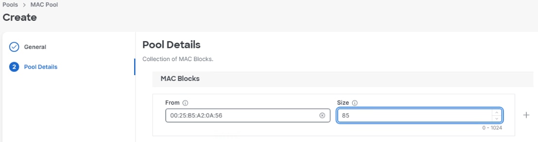
Step 5. Repeat this procedure to create MAC-Pool-B.
Procedure 3. Create UUID Pool
Step 1. Select Configure > Pools. On the right, click Create Pool. Click the radio button to the left of UUID and click Start.
Step 2. Select the correct organization from the drop-down list (for example, AA02-OCP) and provide a name for the pool with the prefix applied (for example, AA02-OCP-UUID-Pool). Enter optional tags and a description. Click Next.
Step 3. Provide an optional Description and click Next.
Step 4. Provide a unique UUID Prefix (for example, a prefix of AA020000-0000-0002 was used).
Step 5. Add a UUID block.
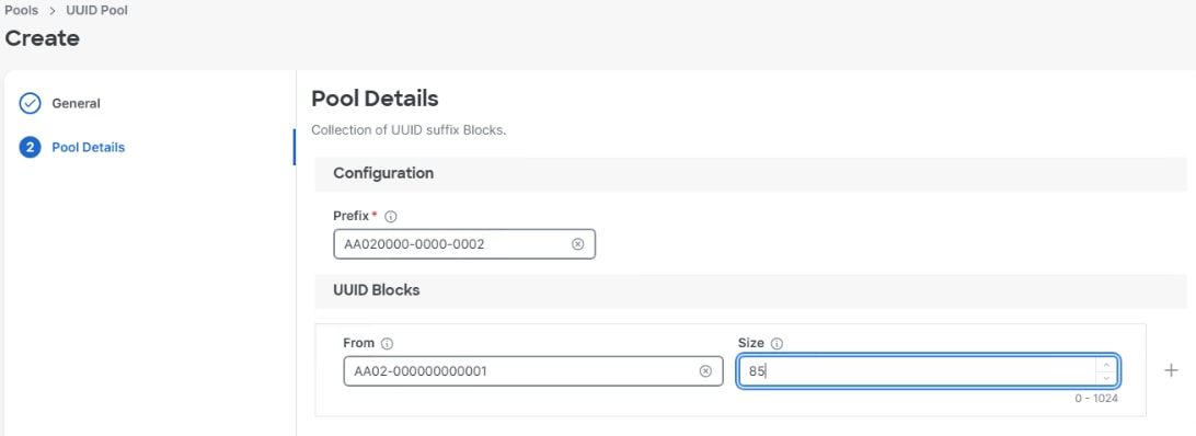
Step 6. Click Create.
Create Server Compute Policies
Procedure 1. Configure Intel M8 Virtualization BIOS Policy
A global BIOS policy will be created in the policy organization that is sharing resources with the OpenShift organization. If this policy already exists, skip to the next procedure.
Step 1. Select Configure > Policies. On the right, click Create Policy. Click the radio button to the left of BIOS and click Start.
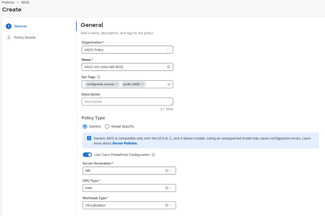
Step 2. Select the correct policy organization from the drop-down list (for example, AA02-Policy) and provide a name for the policy with the prefix applied (for example, AA02-Virt-Intel-M8-BIOS). Enter optional tags and a description. Leave Policy Type Generic selected. Enable Use Cisco Predefined Configuration. Using the drop-down menus, select Server Generation M8, CPU Type Intel, and Workload Type Virtualization. Click Next.
Step 3. On the Policy Details screen, expand Server Management. Use the drop-down list to set the Consistent Device Naming BIOS token to enabled. Click Create to create the BIOS Policy.
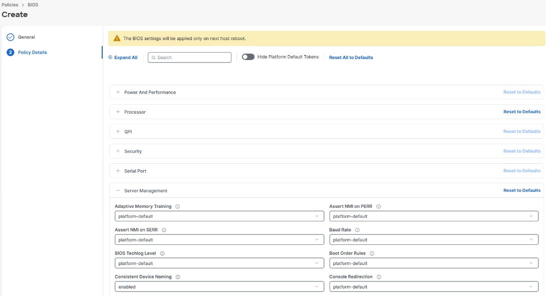
Note: The BIOS Policy settings specified here are from the BIOS Performance and workload: Tuning guide for Cisco UCS M8 Platforms White Paper - Cisco with the Virtualization workload. For other platforms, the appropriate document is listed below:
● Performance Tuning for Cisco UCS M8 Platforms with AMD EPYC 4th Gen and 5th Gen Processors - Cisco
● Performance Tuning Best Practices Guide for Cisco UCS M7 Platforms - Cisco
● Performance Tuning Guide for Cisco UCS M6 Servers - Cisco
● Performance Tuning Guide for Cisco UCS M5 Servers White Paper - Cisco
Step 4. If you have other server platforms other than Intel-based M8, create BIOS policies for the other platforms.
Procedure 2. Configure Boot Order Policy for M.2 Boot
The Boot Order policy for M.2 boot contains both a local storage entry and UCS virtual media entries.
Step 1. Select Configure > Policies. On the right, click Create Policy. Click the radio button to the left of Boot Order and click Start.
Step 2. Select the correct organization from the drop-down list (for example, AA02-OCP) and provide a name for the policy with the prefix applied (for example, AA02-OCP-M.2-Boot-Order). Enter optional tags and a description. Click Next.
Step 3. For Configured Boot Mode, select Unified Extensible Firmware Interface (UEFI).
Step 4. Do not turn on Enable Secure Boot.
Note: NVIDIA GPU drivers are unsigned and will not load if Secure Boot is enabled.
Step 5. Click the Add Boot Device drop-down list and select Virtual Media.
Note: We are entering the Boot Devices in reverse order here to avoid having to move them in the list later.
Step 6. Provide a Device Name (for example, CIMC-Mapped-ISO) and then, for the subtype, select CIMC MAPPED DVD. Click  to collapse the boot entry.
Step 7. Click the Add Boot Device drop-down list and select Virtual Media.
Step 8. Provide a Device Name (for example, KVM-Mapped-ISO) and then, for the subtype, select KVM MAPPED DVD. Click to collapse the boot entry.
Step 9. Click the Add Boot Device drop-down list and select Local Disk.
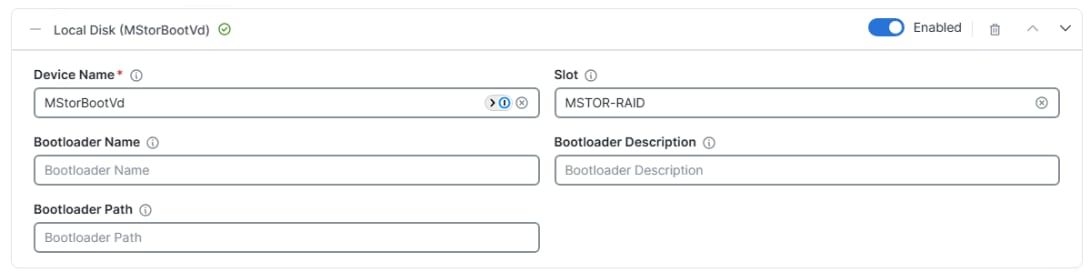
Step 10. For Device Name enter MStorBootVd. For Slot, enter MSTOR-RAID. Click to collapse the boot entry.
Step 11. Verify the order of the boot devices and adjust the boot order as necessary using arrows next to the Delete button. Click Create.
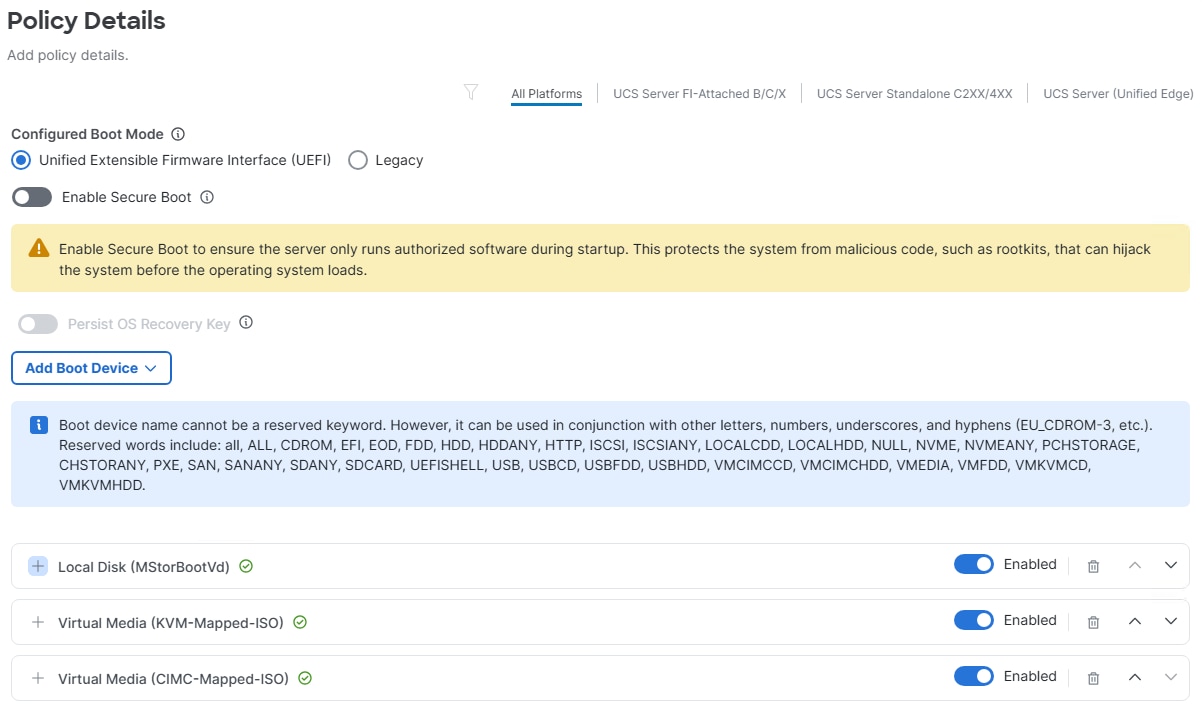
Note: We placed the Virtual Media mounts behind the M.2 boot mount in this policy so that on installation, the M.2 boot disk is blank, and the boot process will fall through to one of the Virtual Media installation ISOs. On subsequent reboots after installation, the boot process will select the M.2 boot disk.
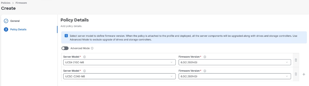
Procedure 3. Configure Firmware Policy for Intel-based M8 Servers (Optional)
The firmware policy sets the default firmware version for Cisco UCS servers. When a server profile is deployed on a server, if the server firmware does not match the firmware version in the firmware policy, the server firmware will be automatically upgraded to the firmware release specified in the firmware policy as part of the server profile deployment.
Step 1. Select Configure > Policies. On the right, click Create Policy. Click the radio button to the left of Firmware and click Start.
Step 2. Select the correct organization from the drop-down list (for example, AA02-OCP) and provide a name for the policy with the prefix applied (for example, AA02-OCP-Server-Firmware). Select the radio button for UCS Server (FI-Attached). Enter optional tags and a description. Click Next.
Step 3. Select a Server Model that is in your environment. Select the corresponding latest Firmware Version.
Step 4. Use the plus sign icon to add additional server models and corresponding firmware.
Step 5. Click Create to create the policy.
Procedure 4. Configure Memory Policy
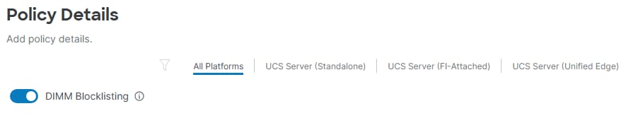
The memory policy configures DIMM Blocklisting, which enables disabling of DIMMs that have uncorrectable ECC errors. This is another global policy. If it already exists, skip to the next procedure.
Step 1. Select Configure > Policies. On the right, click Create Policy. Click the radio button to the left of Memory and click Start.
Step 2. Select the correct organization from the drop-down list to make this a global policy (for example, AA02-Policy) and provide a name for the policy with the prefix applied (for example, AA02-Memory). Enter optional tags and a description. Click Next.
Step 3. Select to enable DIMM Blocklisting. Click Create to create the policy.
Procedure 5. Configure PCIe Connectivity Policy
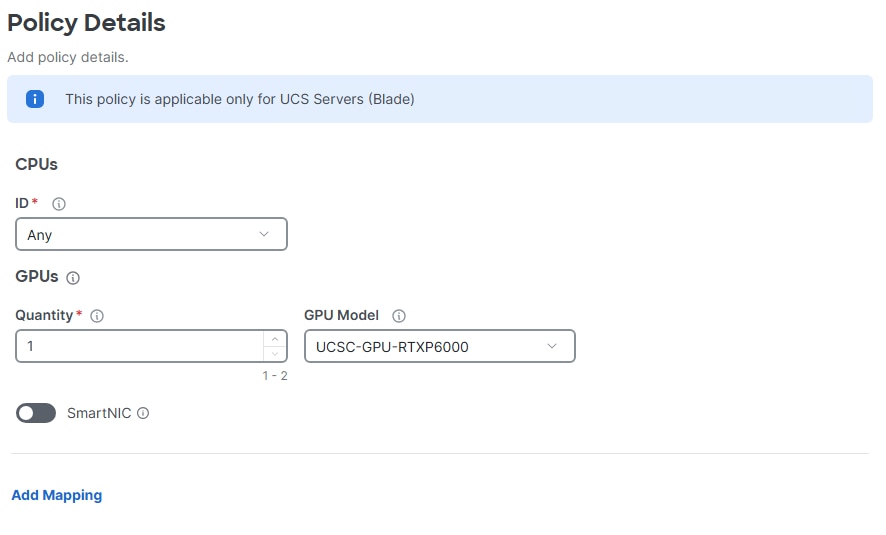
If you have X580p GPU Nodes in your UCS chassis, the PCIe Connectivity Policy sets up GPU mappings to assign the GPUs in the X580p to servers.
Step 1. Select Configure > Policies. On the right, click Create Policy. Click the radio button to the left of PCIe Connectivity and click Start.
Step 2. Select the correct organization from the drop-down list (for example, AA02-OCP) and provide a name for the policy with the prefix applied (for example, AA02-OCP-PCIe-Connectivity-1RTX6000). If the policy is assigning a specific number and type of GPU, add that to the name. Enter optional tags and a description. Click Next.
Step 3. A specific CPU assignment can be created or select Any for automatic assignment. For Quantity, 1 or 2 GPUs can be assigned. For GPU Model, a specific GPU model can be selected if you have more than one GPU model or Any can be selected if all GPUs are the same model. If you have NVLink (NVL) GPUs and intend to connect them to a backend network using SmartNICs in the X9516 X-Fabric modules, select to enable SmartNIC and set SmartNIC Model to either Any or your specific SmartNIC. Click Create to create the policy.
Step 4. Create as many PCIe Connectivity Policies as necessary for the GPUs you have.
Procedure 6. Configure Power Policy
Step 1. Select Configure > Policies. On the right, click Create Policy. Click the radio button to the left of Power and click Start.
Step 2. Select the correct organization from the drop-down list (for example, AA02-OCP) and provide a name for the policy with the prefix applied (for example, AA02-OCP-Server-Power). Enter optional tags and a description. Click Next.
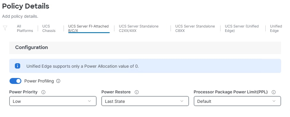
Step 3. Under Policy Details, select the UCS Server (FI-Attached) B/C/X tab. Change the Parameters from the defaults initially listed according to your local policies. Click Create.
Step 4. If necessary, create additional server power policies for specific server types.
Procedure 7. Configure Thermal Policy
Step 1. Select Configure > Policies. On the right, click Create Policy. Click the radio button to the left of Thermal and click Start.
Step 2. Select the correct organization from the drop-down list (for example, AA02-OCP) and provide a name for the policy with the prefix applied (for example, AA02-OCP-Server-Thermal). Enter optional tags and a description. Click Next.
Step 3. Under Policy Details, select the UCS Server (FI-Attached) B/C/X tab. Change the Parameters from the default initially listed according to your local policies. Click Create.
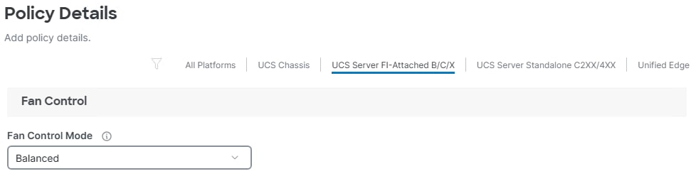
Step 4. If necessary, create additional server thermal policies for specific server types.
Procedure 8. Configure Virtual Media Policy
Step 1. Select Configure > Policies. On the right, click Create Policy. Click the radio button to the left of Virtual Media and click Start.
Step 2. Select the correct organization from the drop-down list (for example, AA02-OCP) and provide a name for the policy with the prefix applied (for example, AA02-OCP-Virtual-Media). Enter optional tags and a description. Click Next.
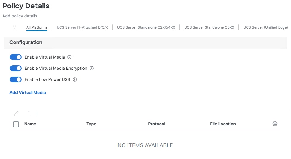
Step 3. Ensure that Enable Virtual Media, Enable Virtual Media Encryption, and Enable Low Power USB are turned on.
Step 4. Do not Add Virtual Media at this time, but the policy can be modified and used to map an ISO for a CIMC Mapped DVD for OS installation. Click Create to create the Virtual Media Policy.
Create Server Management Configuration Policies
Procedure 1. Configure Cisco IMC Access Policy
The IMC Access Policy provides access to the server’s CIMC and can be configured to use either in-band access through the FI uplinks or out-of-band access through the FI management ports or both. Because we would like to give the tenant administrator and users access to the CIMC, we are using in-band access using the OCP-Baremetal-MGMT VLAN and subnet and are not configuring out-of-band access. In this configuration the OOB-MGMT VLAN is piped into the FI uplinks and can also be used to provide OOB-MGMT access to the CIMC with in-band access capabilities. If OOB-MGMT access is used, an IP Pool will need to be created with IPs in the OOB-MGMT subnet.
Step 1. Select Configure > Policies. On the right, click Create Policy. Click the radio button to the left of IMC Access and click Start.
Step 2. Select the correct organization from the drop-down list (for example, AA02-OCP) and provide a name for the policy with the prefix applied (for example, AA02-OCP-IMC-Access). Enter optional tags and a description. Click Next.
Note: Because certain features are not yet enabled for Out-of-Band Configuration (accessed via the Fabric Interconnect mgmt0 ports), if you are using the OOB-MGMT subnet/VLAN, we are bringing in the OOB-MGMT VLAN through the Fabric Interconnect Uplinks and mapping it as the In-Band Configuration VLAN. The OOB-MGMT VLAN was created and mapped in FlexPod Base.
Step 3. Ensure UCS Server (FI-Attached) B/C/X is selected on the right.
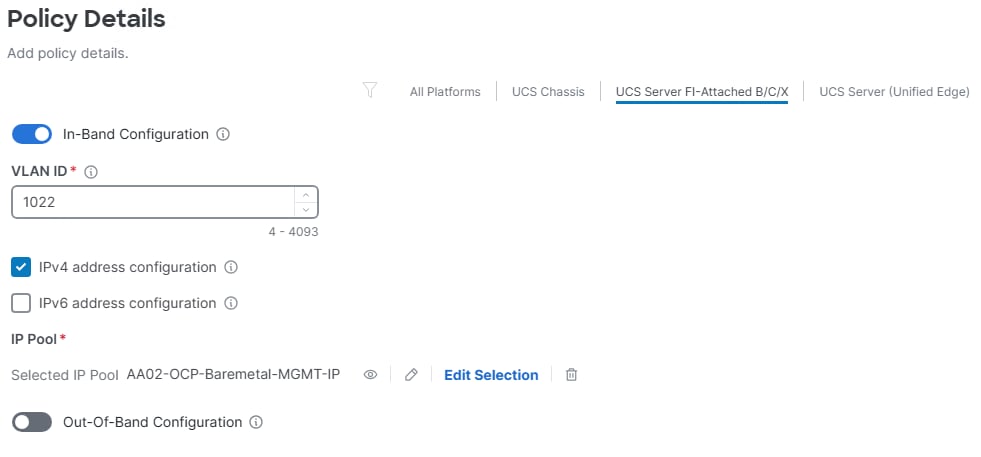
Step 4. Enable In-Band Configuration. Enter the OCP-Baremetal-MGMT VLAN ID (for example, 1022) and select IPv4 address configuration.
Step 5. Click Select IP Pool. Click the radio button to select the OCP-Baremetal-MGMT-IP IP pool created earlier. Click Select.
Step 6. It is not necessary to enable the Out-of-Band Configuration, but if you choose to do so, enable Out-of-Band Configuration and follow the prompts to create an out-of-band IP pool with addresses in the OOB-MGMT subnet.
Step 7. Click Create to create the policy.
Procedure 2. Configure IPMI Over LAN Policy
The IPMI Over LAN Policy is a global policy that can be used to allow both IPMI and Redfish connectivity to Cisco UCS Servers. If this policy already exists, skip to the next procedure.
Step 1. Select Configure > Policies. On the right, click Create Policy. Click the radio button to the left of IPMI Over LAN and click Start.
Step 2. Select the correct organization from the drop-down list (for example, AA02-Policy) and provide a name for the policy with the prefix applied (for example, AA02-IPMIoLAN). Enter optional tags and a description. Click Next.
Step 3. On the right, ensure UCS Server (FI-Attached) B/C/X is selected.
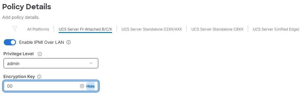
Step 4. Ensure Enable IPMI Over LAN is selected.
Step 5. From the Privilege Level drop-down list, select admin.
Step 6. For Encryption Key, enter 00 to disable encryption. Click Create to create the IPMI Over LAN policy.
Procedure 3. Configure Local User Policy
The Local User Policy creates an alternative user to log into vKVMs and for IPMI/Redfish.
Step 1. Select Configure > Policies. On the right, click Create Policy. Click the radio button to the left of Local User and click Start.
Step 2. Select the correct organization from the drop-down list (for example, AA02-OCP) and provide a name for the policy with the prefix applied (for example, AA02-OCP-Local-User). Enter optional tags and a description. Click Next.
Step 3. Verify that UCS Server (FI-Attached) B/C/X is selected.
Step 4. Verify that Enforce Strong Password is selected.
Step 5. Enter 0 under Password History.
Step 6. Click Add New User.
Step 7. Provide the username (for example, flexadmin), select a role (for example, admin), and provide a password and password confirmation. Choose Custom Account Types can be used to select whether the user account is used only for IPMI or Local access. Click Create to create the policy.
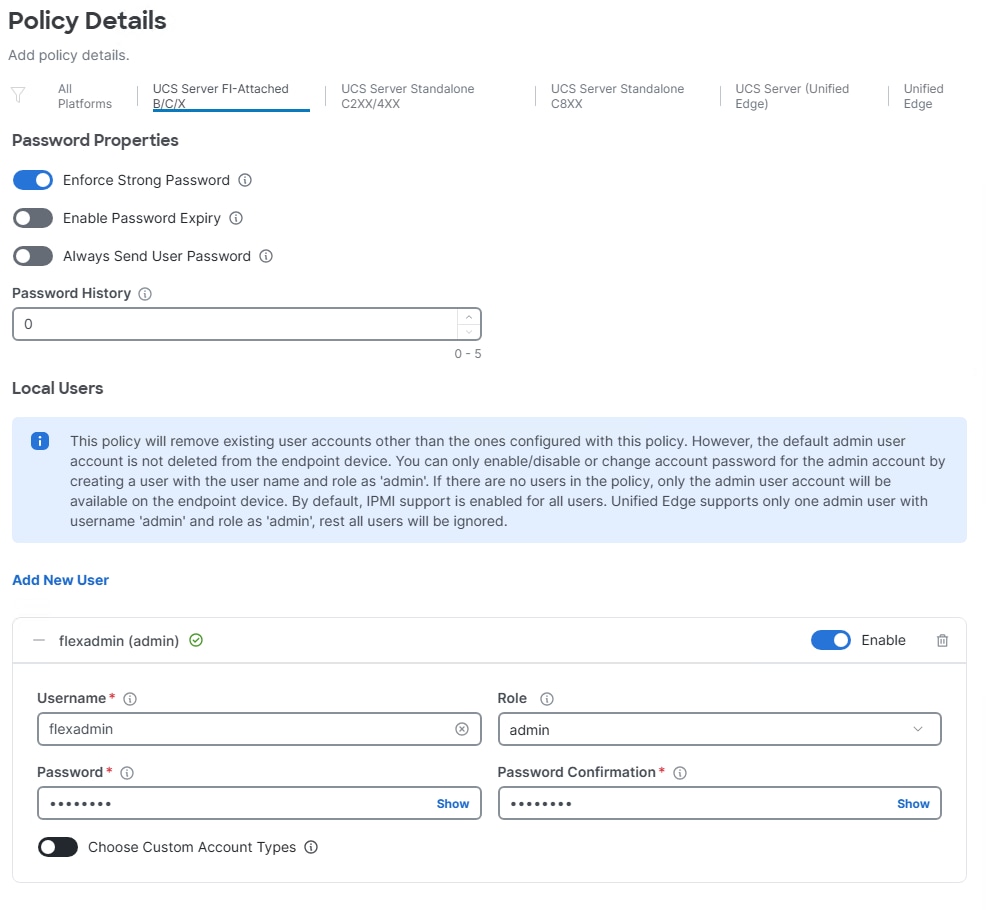
Procedure 4. Configure Virtual KVM Policy
The Virtual KVM policy will be created as a global policy in the FlexPod Policy organization so that it can be shared among multiple tenants. If this policy already exists, skip to the next procedure.
Step 1. Select Configure > Policies. On the right, click Create Policy. Click the radio button to the left of Virtual KVM and click Start.
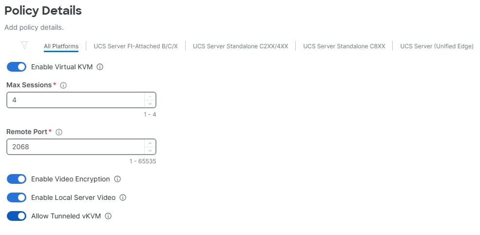
Step 2. Select the correct organization from the drop-down list (for example, AA02-Policy) and provide a name for the policy with the prefix applied (for example, AA02-Virtual-KVM). Enter optional tags and a description. Click Next.
Step 3. Turn on Allow Tunneled vKVM. Click Create to create the policy.
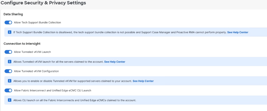
Step 4. To fully enable Tunneled KVM, go to Settings > Security and Privacy and click Configure. Turn on Allow Tunneled vKVM Launch and Allow Tunneled vKVM Configuration. If Tunneled vKVM Launch and Tunneled vKVM Configuration are not Allowed, use the Configure button to change these settings. Optionally, enable Allow Fabric Interconnect and Unified Edge eCMC CLI Launch. Click Save.
Create a Storage Configuration Policy
Procedure 1. Configure the M.2 Boot RAID Storage Policy
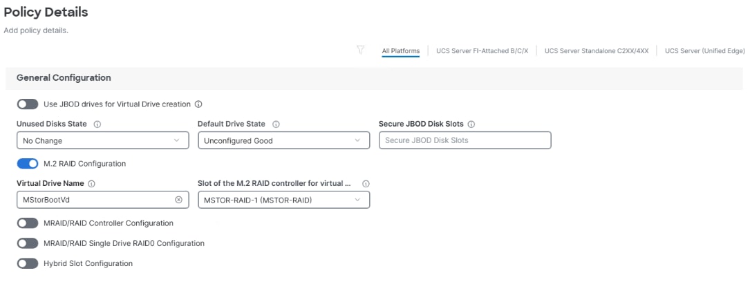
If you have two M.2 drives in your servers, create a policy to mirror these drives using RAID1.
Step 1. Select Configure > Policies. On the right, click Create Policy. Click the radio button to the left of Storage and click Start.
Step 2. Select the correct organization from the drop-down list (for example, AA02-OCP) and provide a name for the policy with the prefix applied (for example, AA02-OCP-M.2-Storage). Enter optional tags and a description. Click Next.
Step 3. Enable M.2 RAID Configuration and leave the default Virtual Drive Name and Slot of the M.2 RAID controller field values, or values appropriate to your environment. Click Create.
Create Server Network Configuration Policies and Templates
Procedure 1. Create Ethernet Network Group Policies
Ethernet Network Group policies will be created and used on applicable vNICs as explained below. The ethernet network group policy defines the VLANs allowed for a particular set of vNICs, therefore four network group policies will be defined for this deployment as listed in Table 5.
Table 5. Ethernet Network Group Policy Values
| Group Policy Name |
Native VLAN |
Apply to vNICs |
Allowed VLANs |
| AA02-OCP-eno5-ENG |
OCP-Baremetal-MGMT (1022) |
eno5 |
OCP-Baremetal-MGMT |
| AA02-OCP-eno6-ENG |
OCP-Infra-iSCSI-A (3012) |
eno6 |
OCP-Infra-iSCSI-A, OCP-Infra-NVMe-TCP-A |
| AA02-OCP-eno7-ENG |
OCP-Infra-iSCSI-B (3022) |
eno7 |
OCP-Infra-iSCSI-B, OCP-Infra-NVMe-TCP-B |
| AA02-OCP-bond0-ENG |
OCP-Infra-NFS (3052) |
eno8, eno9 |
OCP-Infra-NFS, OCP-VM-Net, OCP-Live-Migration |
Note: The eno5 interface is a single interface with UCS Fabric Failover configured and will carry the Baremetal, management, and OpenShift Pod Network traffic. The eno6 and eno7 interfaces will carry NVMe-TCP traffic on VLAN tagged interfaces with UCS Fabric Failover disabled. The eno8 and eno9 interfaces will be configured into an XOR bond as specified in https://access.redhat.com/solutions/67546, will have UCS Fabric Failover configured (the bond will only provide traffic distribution), and will carry NFS (untagged), VM traffic via a bridge, and Live Migration Traffic.
Step 1. Select Configure > Policies. On the right, click Create Policy. Click the radio button to the left of Ethernet Network Group and click Start.
Step 2. Select the correct organization from the drop-down list (for example, AA02-OCP) and provide a name for the policy with the prefix applied from the table above (for example, AA02-OCP-eno5-ENG). Enter optional tags and a description. Click Next.
Step 3. From the Add VLANs drop-down list, select From Policy. Use the radio button to select the VLAN policy from the FI under Shared Policies. Click Next. Use the checkboxes to select the VLANs from the ENG listing in the table above. Click Select.
Note: Note that the policy setup in FlexPod Base where a shared policy organization was setup and it shares resources with the OpenShift organization allows the VLAN selection from policy to take place.
Step 4. If a VLAN is the native VLAN for the policy, click the three dots to the right of the VLAN and select Set Native VLAN. Click Create to create the Ethernet Network Group policy.
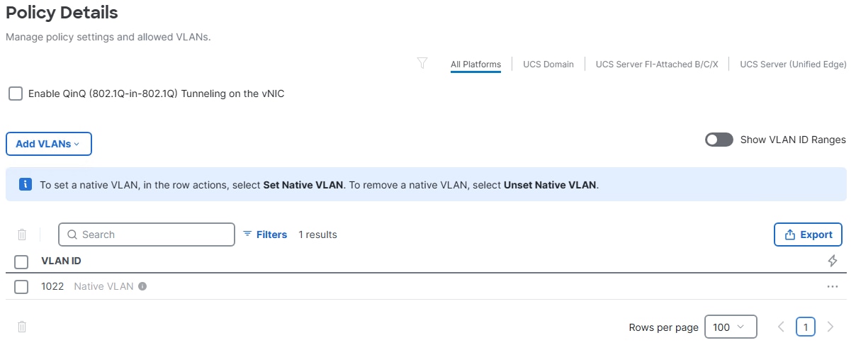
Step 5. Repeat steps 1- 4 to create the remaining ENG policies.
Procedure 2. Create Ethernet Network Control Policy
The Ethernet Network Control Policy is used to enable Cisco Discovery Protocol (CDP) and Link Layer Discovery Protocol (LLDP) for the vNICs. A single global policy will be created here and reused for all the vNICs. If this policy already exists, skip to the next procedure.
Step 1. Select Configure > Policies. On the right, click Create Policy. Click the radio button to the left of Ethernet Network Control and click Start.
Step 2. Select the correct global organization from the drop-down list (for example, AA02-Policy) and provide a name for the policy with the prefix applied (for example, AA02-Enable-CDP-LLDP-ENC). Enter optional tags and a description. Click Next.
Step 3. Click Next.
Step 4. Enable Cisco Discovery Protocol (CDP) and Enable Transmit and Enable Receive under LLDP. Click Create to create the policy.
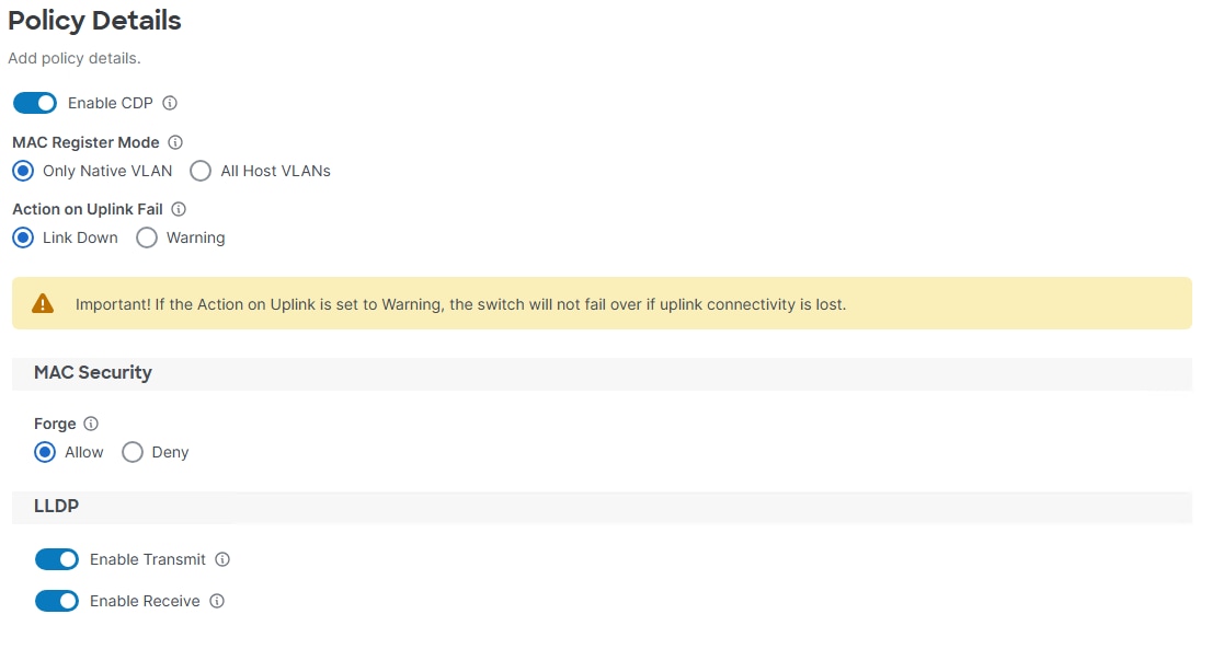
Procedure 3. Create Ethernet QoS Policies
The Ethernet QoS policy is used to set the maximum transmission unit (MTU), Class of Service, and Priority for the assigned vNIC. This procedure will create two global QoS policies with MTUs 1500 and 9000, both configured with Priority Best-effort.
Step 1. Select Configure > Policies. On the right, click Create Policy. Click the radio button to the left of Ethernet QoS and click Start.
Step 2. Select the correct global organization from the drop-down list (for example, AA02-Policy) and provide a name for the policy with the prefix applied (for example, AA02-Jumbo-Best-Effort-QoS). Enter optional tags and a description. Click Next.
Step 3. Change the MTU, Bytes value to 9000. Leave all other fields at the default values. Click Create.
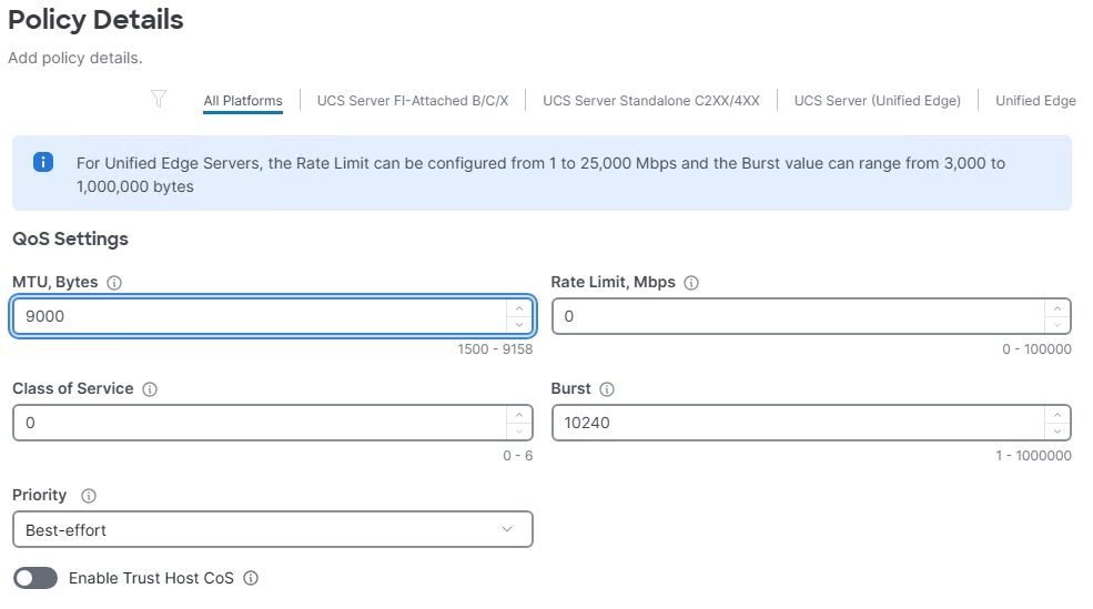
Step 4. Select Configure > Policies. On the right, click Create Policy. Click the radio button to the left of Ethernet QoS and click Start.
Step 5. Select the correct global organization from the drop-down list (for example, AA02-Policy) and provide a name for the policy with the prefix applied (for example, AA02-MTU-1500-Best-Effort-QoS). Enter optional tags and a description. Click Next.
Step 6. Leave the MTU, Bytes value set to 1500. Leave all other fields at the default values. Click Create.
Procedure 4. Create Ethernet Adapter Policy
The ethernet adapter policy is used to set the interrupts, send, and receive queues, and queue ring size. The values are set according to the best-practices guidance for the operating system in use. Cisco Intersight provides a default Linux Ethernet Adapter policy for typical Linux deployments, including CoreOS and OpenShift.
You can optionally configure a tweaked ethernet adapter policy for additional hardware receive queues handled by multiple CPUs in scenarios where there is a lot of traffic and multiple flows. In this deployment, a modified ethernet adapter policy, AA02-OCP-EthAdapter-16RXQs, is created and attached to bonded and NVMe-TCP vNICs. Management vNICs will use the default Linux-v2 Ethernet Adapter policy.
Table 6. Ethernet Adapter Policy association to vNICs
| Policy Name |
vNICs |
| AA02-OCP-EthAdapter-Linux-v2 |
eno5 |
| AA02-OCP-EthAdapter-16RXQs |
eno6, eno7, eno8, eno9 |
Step 1. Select Configure > Policies. On the right, click Create Policy. Click the radio button to the left of Ethernet Adapter and click Start.
Step 2. Select the correct organization from the drop-down list (for example, AA02-OCP) and provide a name for the policy with the prefix applied from the table above (for example, AA02-OCP-EthAdapter-Linux-v2). Enter optional tags and a description.
Step 3. Click Select Cisco Provided Configuration under Cisco Provided Ethernet Adapter Configuration.
Step 4. From the list, use the radio button to select Linux-v2. Click Select.
Step 5. Click Next.
Step 6. Do not change any values and click Create.
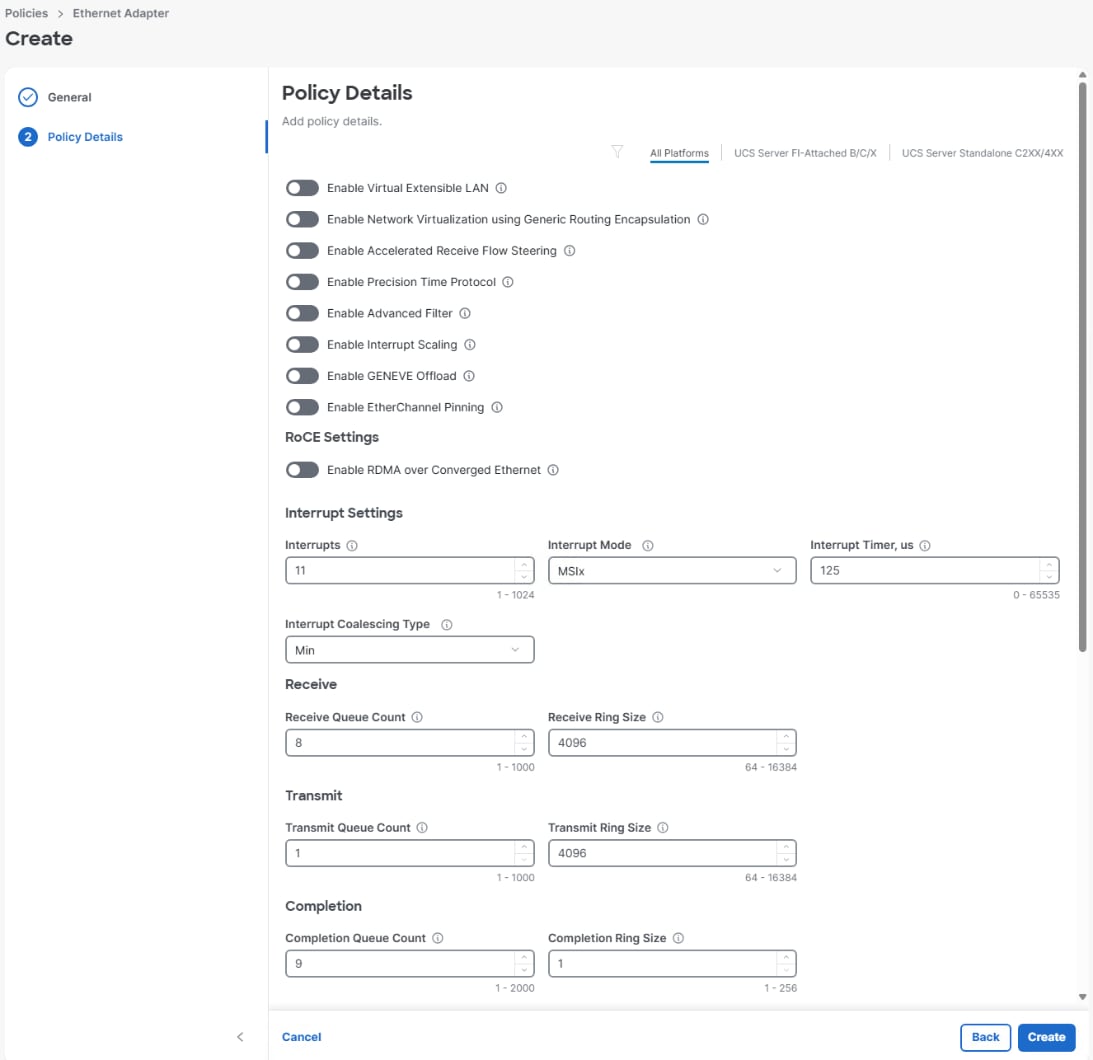
Step 7. Select Configure > Policies. On the right, click Create Policy. Click the radio button to the left of Ethernet Adapter and click Start.
Step 8. Select the correct organization from the drop-down list (for example, AA02-OCP) and provide a name for the policy with the prefix applied from the table above (for example, AA02-OCP-EthAdapter-16RXQs). Enter optional tags and a description.
Step 9. Click Select Cisco Provided Configuration under Cisco Provided Ethernet Adapter Configuration.
Step 10. From the list, use the radio button to select Linux-v2. Click Select.
Step 11. Click Next.
Step 12. For the AA02-OCP-EthAdapter-16RXQs policy, make the following modifications to the policy:
● Increase Interrupts to 19
● Increase Receive Queue Count to 16
● Increase Completion Queue Count to 17
● Ensure Receive Side Scaling is enabled
Step 13. Click Create to create the policy.
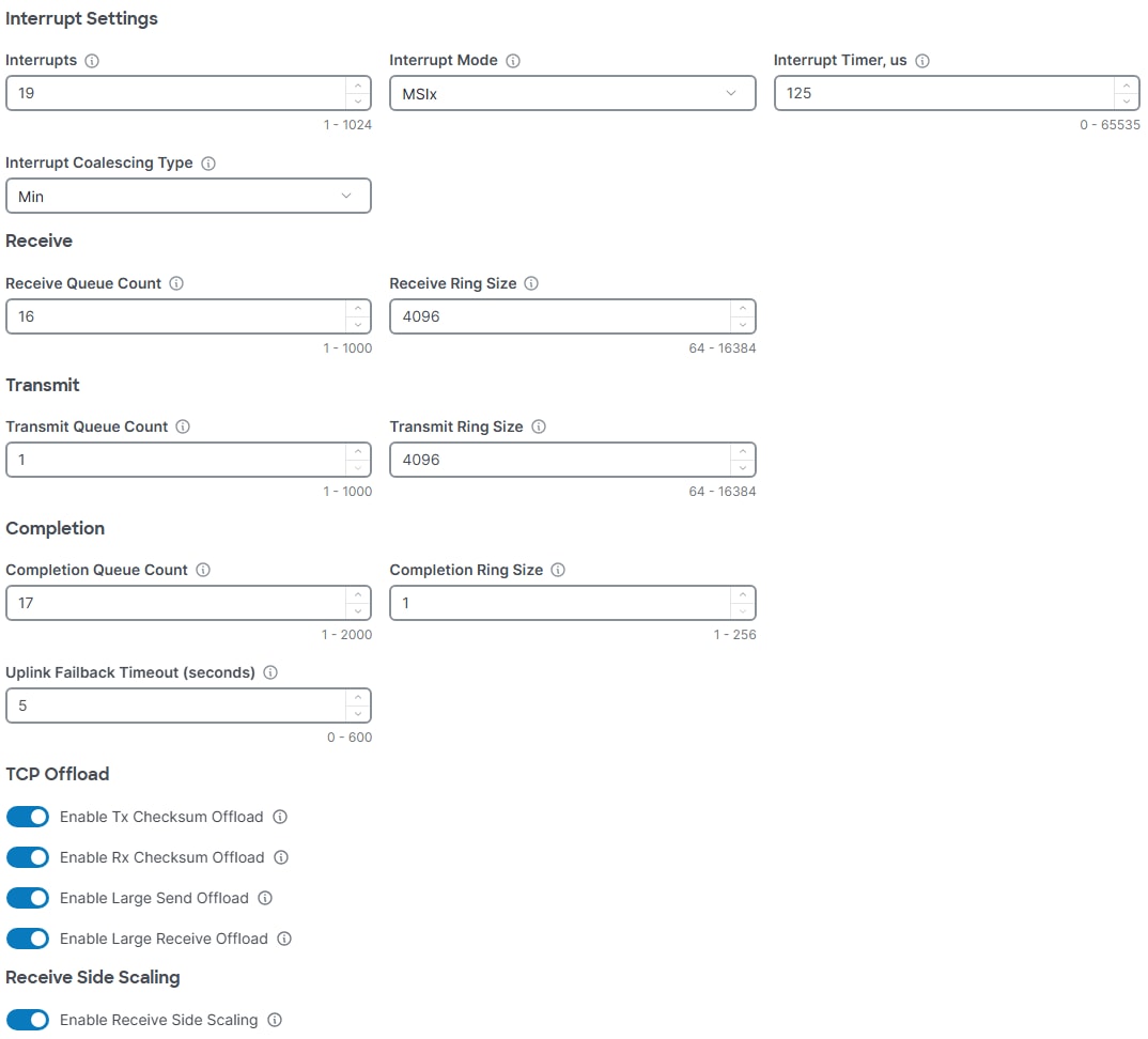
Procedure 5. Configure vNIC Templates
vNIC Templates define the group of policies for each vNIC instance type.
Table 7. vNIC Templates for OpenShift Hosts
| vNIC Template Name |
MAC Pool |
Switch ID |
Failover |
Ethernet Network Group |
MTU |
Ethernet Adapter |
| <prefix>-eno5 |
MAC-Pool-A |
A |
Y |
eno5-ENG |
1500 |
EthAdapter-Linux-v2 |
| <prefix>-eno6 |
MAC-Pool-A |
A |
N |
eno6-ENG |
Jumbo |
EthAdapter-16RXQs |
| <prefix>-eno7 |
MAC-Pool-B |
B |
N |
eno7-ENG |
Jumbo |
EthAdapter-16RXQs |
| <prefix>-bond0-A |
MAC-Pool-A |
A |
Y |
bond0-ENG |
Jumbo |
EthAdapter-16RXQs |
| <prefix>-bond0-B |
MAC-Pool-B |
B |
Y |
bond0-ENG |
Jumbo |
EthAdapter-16RXQs |
Note: For the bonded interfaces, it is recommended to enable Failover.
Step 1. Select Configure > Templates > vNIC Templates. On the right, click Create vNIC Template.
Step 2. Select the correct organization from the drop-down list (for example, AA02-OCP) and provide a name for the template with the prefix applied (for example, AA02-OCP-eno5). Click Next.
Step 3. Click Select Pool, use the radio button to select the corresponding MAC pool from the table above and click Select. Select the corresponding Switch ID from the table above. Leave Consistent Device Naming (CDN) set to vNIC Name and set Failover according to the table. For the Ethernet Network Group policy, select the policy from the table above. For Ethernet Network Control, select the Enable-CDP-LLDP-ENC global shared policy. For Ethernet QoS, select the Best-Effort-QoS global shared policy for the appropriate MTU from Table 7. For the Ethernet Adapter policy, select the policy from the table above. Do not select an iSCSI Boot policy. Click Create.
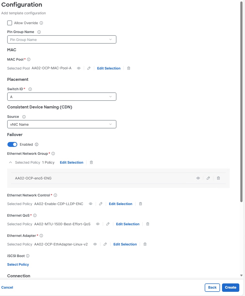
Step 4. Repeat steps 1 – 3 to create the remaining vNIC Templates in Table 7.
Procedure 6. Configure M.2 Boot LAN Connectivity Policies
The LAN connectivity policy defines the connections and network communication resources between the server and the LAN. This policy uses pools to assign MAC addresses to servers and to identify the vNICs that the servers use to communicate with the network.
For consistent vNIC placement, manual vNIC placement is utilized. Additionally, the assumption is being made here that each server contains only one VIC card and Simple placement, which adds vNICs to the first VIC, is being used. If you have more than one VIC in a server, the Advanced placement will need to be used.
Two LAN Connectivity Polies are configured as listed in the tables below.
Table 8. vNIC placement for OpenShift Control Plane Hosts
| vNIC Name |
vNIC Template |
PCI Order |
| eno5 |
<prefix>-eno5 |
0 |
Table 9. vNIC placement for OpenShift Worker Hosts
| vNIC Name |
vNIC Template |
PCI Order |
| eno5 |
<prefix>-eno5 |
0 |
| eno6 |
<prefix>-eno6 |
1 |
| eno7 |
<prefix>-eno7 |
2 |
| eno8 |
<prefix>-bond0-A |
3 |
| eno9 |
<prefix>-bond0-B |
4 |
Step 1. Select Configure > Policies. On the right, click Create Policy. Click the radio button to the left of LAN Connectivity and click Start.
Step 2. Select the correct organization from the drop-down list (for example, AA02-OCP) and provide a name for the policy with the prefix applied from the table above (for example, AA02-OCP-M.2-Boot-CP-LANConn). Select the UCS Server (FI-Attached) Target Platform. Enter optional tags and a description. Click Next.
Step 3. Leave None selected under IQN and under vNIC Configuration, select Manual vNICs Placement.
Step 4. Use the Add drop-down list to select vNIC from Template.
Step 5. Enter the name for the vNIC from the first table above (for example, eno5) and click Select vNIC Template.
Note: It is important to use the exact name from the table above with nothing else to ensure that Consistent Device Naming (CDN) works properly.
Step 6. Use the radio button to select the vNIC template from the table above and click Select. Enter the PCI Order number from the table above and click Add.
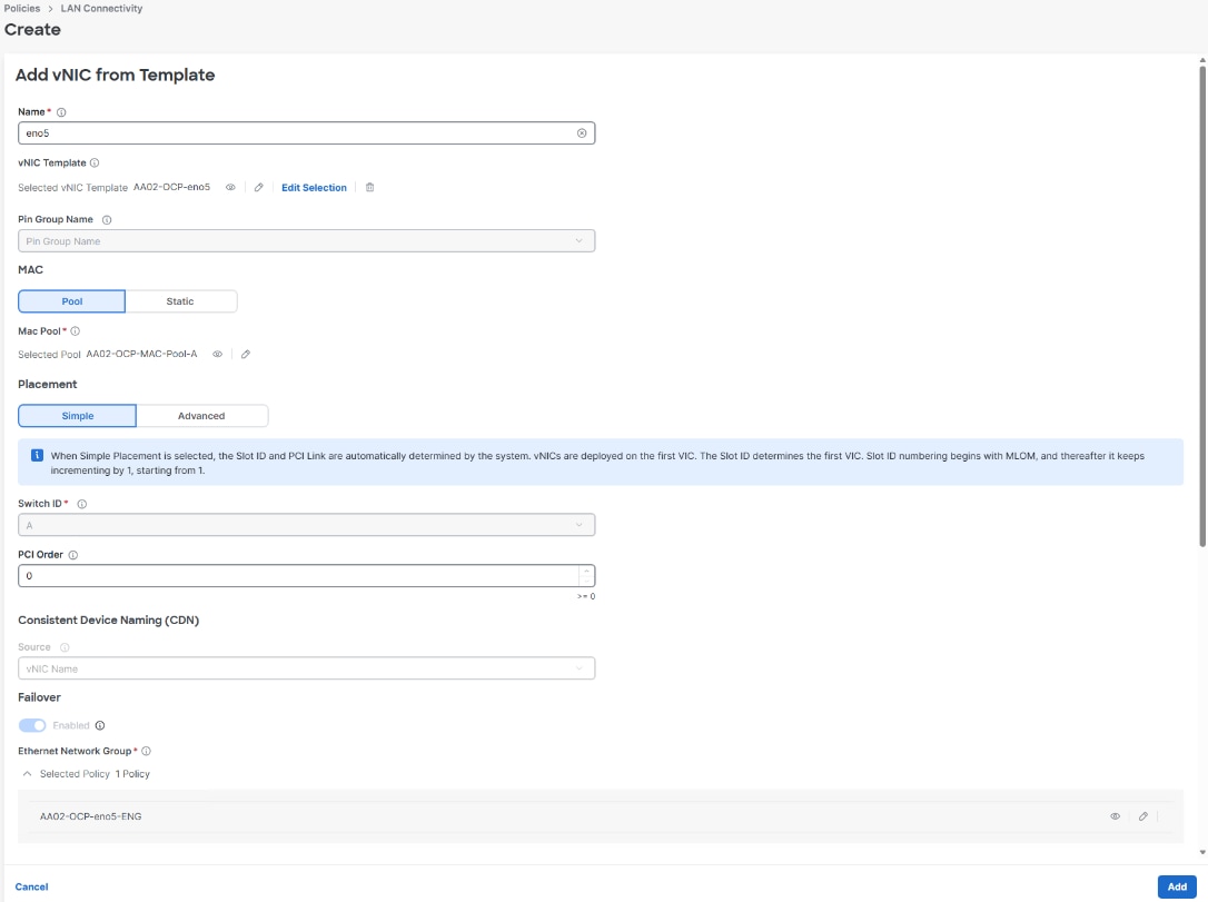
Step 7. Click Create.
Step 8. Select Configure > Policies. On the right, click Create Policy. Click the radio button to the left of LAN Connectivity and click Start.
Step 9. Select the correct organization from the drop-down list (for example, AA02-OCP) and provide a name for the policy with the prefix applied from the table above (for example, AA02-OCP-M.2-Boot-Worker-LANConn). Select the UCS Server (FI-Attached) Target Platform. Enter optional tags and a description. Click Next.
Step 10. Leave None selected under IQN and under vNIC Configuration, select Manual vNICs Placement.
Step 11. Use the Add drop-down list to select vNIC from Template.
Step 12. Enter the name for the vNIC from the second table above (for example, eno5) and click Select vNIC Template.
Step 13. Use the radio button to select the vNIC template from the table above and click Select. Enter the PCI Order number from the table above and click Add.
Step 14. Repeat steps 11-13 to add the remaining vNICs to the LAN Connectivity policy. Click Create to create the policy.
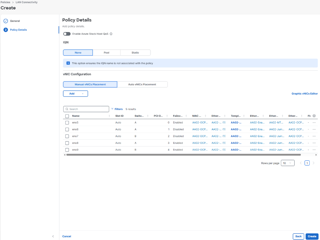
Create Server Profile Templates
Procedure 1. Create OpenShift Control Plane and Worker Host Server Profile Templates and Derive Server Profiles
Control Plane and Worker Server Profile Templates will be created for Intel-based M8 server OpenShift CoreOS hosts. These templates can be used to derive server profiles for blades and rackmounts.
Step 1. Select Configure > Templates > UCS Server Profile Templates. On the right, click Create UCS Server Profile Template.
Step 2. Select the correct organization from the drop-down list (for example, AA02-OCP) and provide a name for the template with the prefix applied (for example, AA02-OCP-Intel-M8-M.2-Boot-CP). Select UCS Server (FI-Attached). Enter optional tags and a description. Click Next.
Step 3. In the Compute Configuration window, use Select Pool under UUID Pool to select the UUID Pool created earlier. To the right of BIOS (Shared), Boot Order, Firmware (optional), Memory (Shared), Power, Thermal, and Virtual Media, use Select Policy to select policies created earlier. Do not select a PCIe Connectivity policy at this time. Click Next.
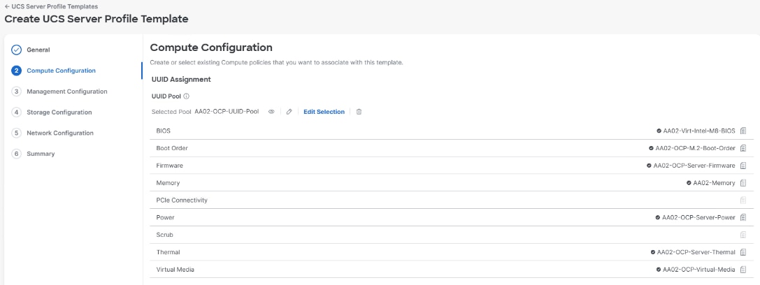
Step 4. In the Management Configuration window, to the right of IMC Access, IPMI Over LAN (Shared), Local User, SNMP (Shared and optional), and Virtual KVM (Shared), use Select Policy to select policies created earlier. Click Next.
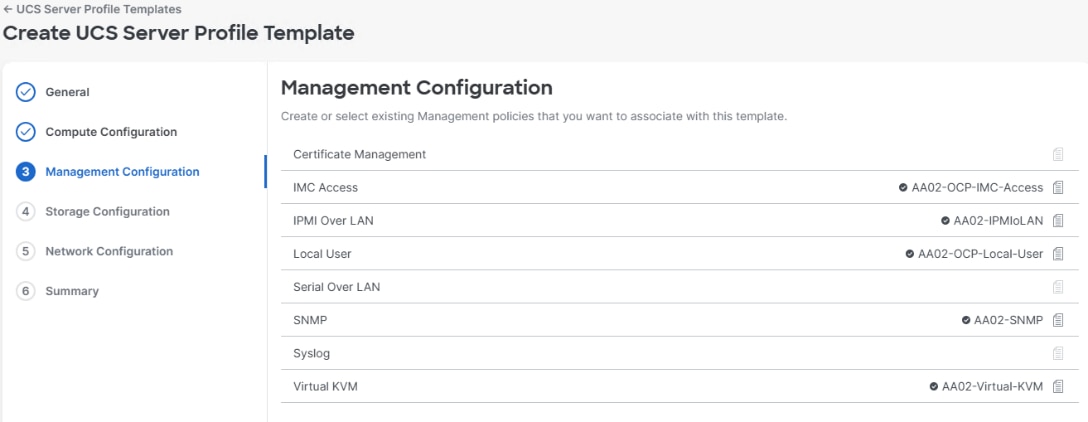
Step 5. In the Storage Configuration window, to the right of Storage, use Select Policy to select the policy created earlier. Click Next.
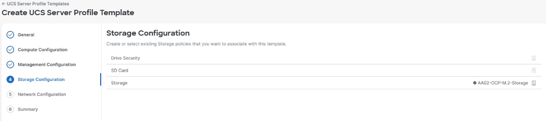
Step 6. In the Network Configuration window, to the right of LAN Connectivity, select the Control Plane (-CP) LAN Connectivity Policy and use Select Policy to select it. Click Next.
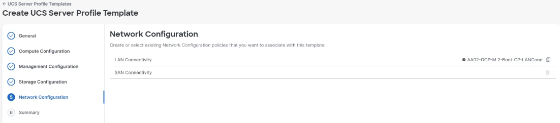
Step 7. Review the Summary information.
Step 8. In your OpenShift deployment, if any nodes are planned to be only Control Plane nodes, click Derive Profiles. If your deployment has only combination Control Plane and Worker nodes plus additional worker nodes, click Close and skip to step 12.
Step 9. Using the checkboxes, select 3 servers for Control Plane server profiles. Click Next.
Step 10. Put in a Profile Name Prefix, Digits Count, and Start Index for Suffix to derive desired server profile names or put the names in manually. Click Next.
Step 11. Review the Summary information and click Derive.
Step 12. Select Configure > Templates > UCS Server Profile Templates. Click the three dots to the right of the just-created OpenShift Control Plane server template and select Clone.
Step 13. Ensure the OpenShift Organization is selected and click Next.
Step 14. Name the clone (for example, AA02-OCP-Intel-M8-M.2-Boot-Worker) and click Clone.
Step 15. Back under UCS Server Profile Templates, click the three dots to the right of the newly-cloned Worker template and click Edit. Click Next four times to get to Network Configuration.
Step 16. Click the current LAN Connectivity Policy to bring up the policy selection window. Select the Worker LAN Connectivity Policy and click Save. Click Select again to select the policy with multiple vNICs. Click Next.
Step 17. Review the Summary Information and click Derive Profiles.
Step 18. Select all servers that will be assigned as Worker nodes including combination Control Plane and Worker nodes. Click Next.
Step 19. Put in a Profile Name Prefix, Digits Count, and Start Index for Suffix to derive desired server profile names or put the names in manually. Click Next.
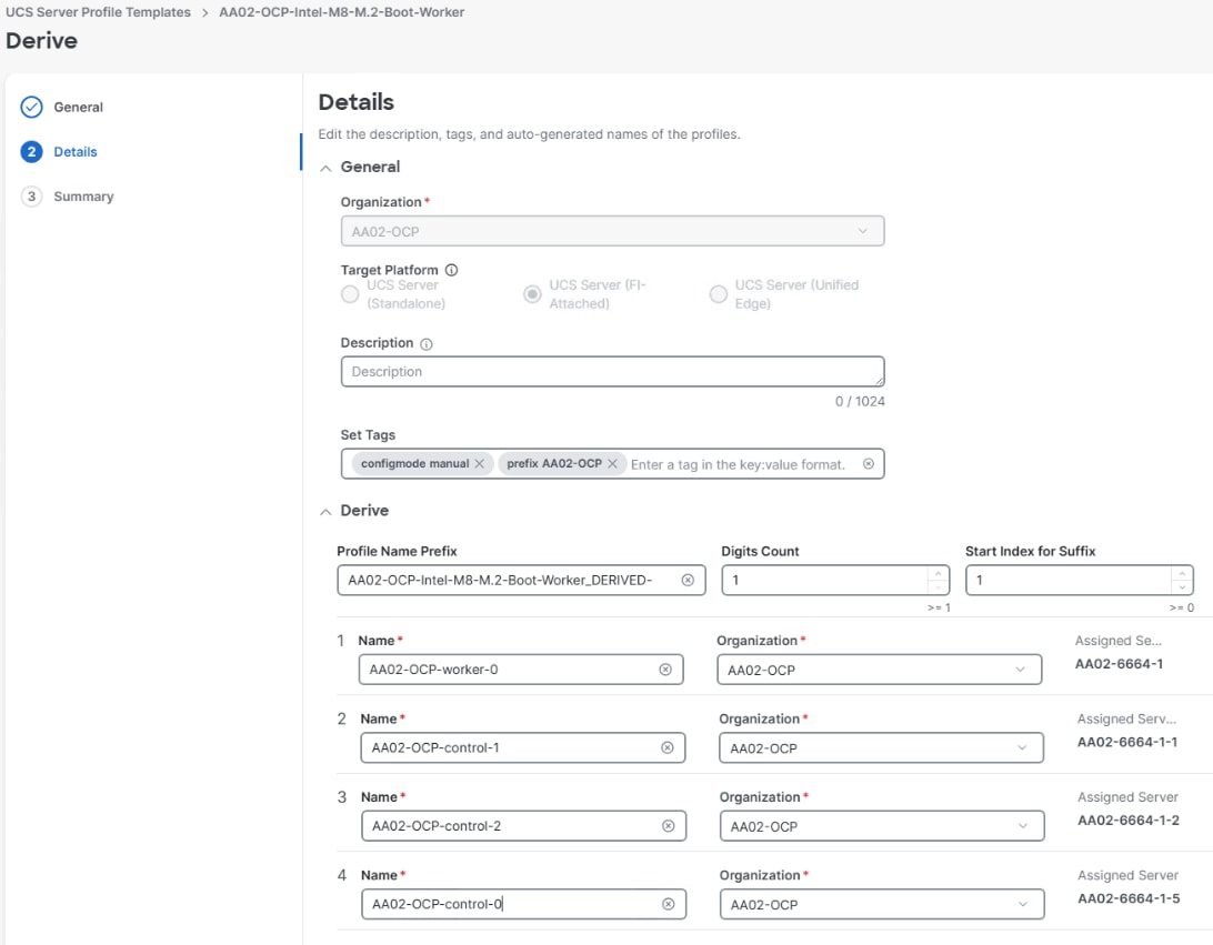
Step 20. Review the summary information and click Derive.
Procedure 2. Connect X580p GPUs to Servers
If you have X580p module(s) in your chassis with X9516 X-Fabric modules and UCSX-V5-PCIME cards in the servers, you can connect the GPUs inside the X580p to the servers. In this validation, an X580p was placed in chassis slots 3 and 4. Servers in slots 1 and 2 can be connected to the GPUs in the X580p.
Step 1. Select Profiles > UCS Server Profiles. For a server that you want to connect to one or more GPUs, click the three dots to the right of the server profile and choose Detach from Template to remove the server profile from the server profile template. Click Detach.
Step 2. Click the ellipses to the right of the server profile again and choose Edit. Click Next two times to get to the Compute Configuration window. To the right of PCIe Connectivity, click Select Policy, select a PCIe Connectivity policy, and click Select. Click Next.
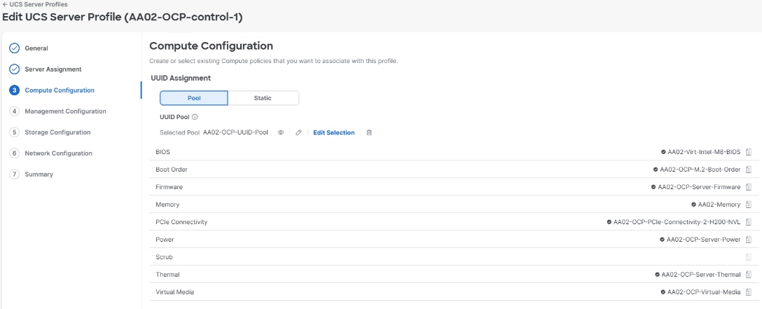
Step 3. The changes to the policy are now saved in Intersight. Click Close.
Step 4. Repeat steps 1 – 3 to attach more X580p GPUs to servers.
Procedure 3. Deploy Server Profiles
Step 1. Select Profiles > UCS Server Profiles. Use the checkboxes to select all OpenShift server profiles. Use the More actions pulldown and choose Deploy. Select the checkbox to the left of Reboot immediately to activate. Click Deploy.
Step 2. The deployment can take time. Monitor Requests to check deployment status.
OpenShift Installation and Configuration
This chapter contains the following:
● OpenShift Installation Requirements
● Clone Volumes across Namespaces
● Add an Additional Administrative User to the OpenShift Cluster
● Deploy OpenShift Internal Image Registry
● Add a Worker Node to an OpenShift Cluster
● Deploy a Sample Containerized Application
● Deploy OpenShift Virtualization
● Data Protection for VMs in OpenShift Virtualization using NetApp Trident Protect
In this validation, OpenShift 4.20 is deployed on the Cisco UCS infrastructure on M.2 virtual drives or single M.2 drives. The reason M.2 boot was chosen instead of iSCSI boot is that although an iSCSI-booted cluster can be initially installed with the Red Hat Assisted Installer, if the Red Hat Assisted Installer’s Add Hosts capability is used to either add an iSCSI-booted node to a cluster or to reinstall Red Hat CoreOS on a node, if this node is rebooted it will lose access to its iSCSI boot disk during the boot process. In this validation, three combination control-plane and worker nodes are deployed are deployed on Cisco UCS X210c M8 servers and one worker node is deployed on a Cisco UCS C240 M8 and additional worker nodes can easily be added to increase the scalability of the solution. This document will guide you through the process of using the Assisted Installer to deploy OpenShift 4.20.
Note: Because the Red Hat Assisted Installer’s Add Hosts capability cannot be used to successfully add a node to a cluster or to reinstall CoreOS on a host, iSCSI boot of OpenShift is not supported with FlexPod.
OpenShift Installation Requirements
The Red Hat OpenShift Assisted Installer provides support for installing OpenShift on bare metal nodes. This guide provides a methodology to achieving a successful installation using the Assisted Installer.
FlexPod for OpenShift utilizes the Assisted Installer for OpenShift installation therefore when provisioning and managing the FlexPod infrastructure, you must provide all the supporting cluster infrastructure and resources, including an installer VM or host, networking, storage, and individual cluster machines.
The following supporting cluster resources are required for the Assisted Installer installation:
● The control plane and compute machines that make up the cluster
● Cluster networking
● Storage for the cluster infrastructure and applications
● The Installer VM or Host
The following infrastructure services need to be deployed to support the OpenShift cluster, during the validation of this solution we have provided VMs on your hypervisor of choice to run the required services. You can use existing DNS and DHCP services available in the data center.
There are various infrastructure services prerequisites for deploying OpenShift 4.20. These prerequisites are as follows:
● DNS and DHCP services – these services were configured on Microsoft Windows Server VMs in this validation
● NTP Distribution was done with the Cisco Nexus switches
● Specific DNS entries for deploying OpenShift – added to the DNS server
● A Linux VM for initial automated installation and cluster management – a RHEL 9 / Rocky Linux 9 VM with appropriate packages
NTP
Each OpenShift node in the cluster must have access to at least two NTP servers.
NICs
vNICs configured on the Cisco UCS servers based on the design previously discussed.
DNS
Clients access the OpenShift cluster nodes over the bare metal network. Configure a subdomain or subzone where the canonical name extension is the cluster name.
The following domain and OpenShift cluster names are used in this deployment guide:
● Base Domain: flexpodb4.cisco.com
● OpenShift Cluster Name: aa02-ocp
The DNS domain name for the OpenShift cluster should be the cluster name followed by the base domain, for example, aa02-ocp.flexpodb4.cisco.com.
Table 10 lists the information for fully qualified domain names used during validation. The API and Nameserver addresses begin with canonical name extensions. The hostnames of the control plane and worker nodes are exemplary, so you can use any host naming convention you prefer.
| Usage |
Hostname |
IP Address |
| API |
api.aa02-ocp.flexpodb4.cisco.com |
10.102.2.247 |
| Ingress LB (apps) |
*.apps.aa02-ocp.flexpodb4.cisco.com |
10.102.2.248 |
| control-0 |
control0.aa02-ocp.flexpodb4.cisco.com |
10.102.2.200 |
| control-1 |
control1.aa02-ocp.flexpodb4.cisco.com |
10.102.2.201 |
| control-2 |
control2.aa02-ocp.flexpodb4.cisco.com |
10.102.2.202 |
| worker-0 |
worker0.aa02-ocp.flexpodb4.cisco.com |
10.102.2.203 |
DHCP
For the bare metal network, a network administrator must reserve several IP addresses, including:
● One IP address for the API endpoint
● One IP address for the wildcard Ingress endpoint
● One IP address for each OpenShift node (DHCP server assigns to the node)
Note: Obtain the MAC addresses of the bare metal Interfaces from the UCS Server Profile for each node to be used in the DHCP configuration to assign reserved IP addresses (reservations) to the nodes. The KVM IP address also needs to be gathered for the nodes from the server profiles.
Procedure 1. Gather MAC Addresses of Node Bare Metal Interfaces
Step 1. Log into Cisco Intersight.
Step 2. Select Configure > Profiles > Server Profile (for example, AA02-OCP-worker-0).
Step 3. In the center pane, select Configuration > vNICs / vHBAs.
Step 4. Record the MAC address for NIC Interface eno5.
Step 5. Select the General tab and select Identifiers in the center pane.
Step 6. Record the Management IP assigned out of the AA02-OCP-BareMetal-IP-Pool.
Table 11 lists the IP addresses used for the OpenShift cluster including bare metal network IPs and UCS KVM Management IPs for IPMI or Redfish access.
Table 11. Host BMC Information
| Hostname |
IP Address |
UCS KVM Mgmt. IP Address |
BareMetal MAC Address (eno5) |
| control-0 |
10.102.2.200 |
10.102.2.239 |
00:25:B5:A2:0A:5C |
| control-1 |
10.102.2.201 |
10.102.2.238 |
00:25:B5:A2:0A:56 |
| control-2 |
10.102.2.202 |
10.102.2.237 |
00:25:B5:A2:0A:59 |
| worker-0 |
10.102.2.203 |
10.102.2.240 |
00:25:B5:A2:0A:5F |
Step 7. From Table 11, enter the hostnames, IP addresses, MAC addresses, and NTP server addresses as reservations in your DHCP and DNS server(s) or configure the DHCP server to dynamically update DNS.
Step 8. In the Nexus Dashboard network configuration, DHCP relay was used to relay the DHCP requests from the storage VLANs to the Baremetal-MGMT VLAN. Create a DHCP scope for each storage VLAN and subnet where the IPs assigned by the scope do not overlap with storage LIF IPs. Either enter the nodes in the DNS server or configure the DHCP server to forward entries to the DNS server. For the cluster nodes, create reservations to map the hostnames to the desired IP addresses.
Step 9. Setup either a VM or spare server as an OCP-Installer machine with the network interface connected to the Bare Metal VLAN and install either Red Hat Enterprise Linux (RHEL) 9.8 or Rocky Linux 9.8 Server with GUI and create an administrator user. Once the VM or host is up and running, update it and install and configure XRDP. Also, install Microsoft Edge onto this machine. Connect to this host with a Windows Remote Desktop client as the admin user.
Procedure 2. Install Red Hat OpenShift using the Assisted Installer
Use the following steps to install OpenShift from the OCP-Installer VM.
Step 1. From the Installer desktop, open a terminal session and create an SSH key pair to use to communicate with the OpenShift hosts:
ssh-keygen -t ed25519 -N '' -f ~/.ssh/id_ed25519
Step 2. Copy the public SSH key to the user directory:
cp ~/.ssh/id_ed25519.pub ~/
Step 3. Add the private key to the ssh-agent:
eval "$(ssh-agent)"
ssh-add ~/.ssh/id_ed25519
Step 4. If installing Isovalent Cilium in place of OVN networking, using Microsoft Edge on the installer VM, connect to https://docs.isovalent.com/iep/v25.11/ink/install/openshift.html. If you put in your email address to access the site, click the access link in the email to access the Isovalent documentation site. You will then need to paste https://docs.isovalent.com/iep/v25.11/ink/install/openshift.html into the browser window to get to the correct page. On the Isovalent Enterprise Platform 25.11 documentation page, under Prerequisites > OpenShift > OpenShift Installer > Cilium Tuning > Download Isovalent Networking for Kubernetes manifests, click the Download Link to download the cilium v1.18 manifests.
Step 5. If installing Isovalent Cilium in place of OVN networking, extract the cilium v1.18 manifests:
mkdir ~/<openshift cluster name>
mkdir ~/<openshift cluster name>/cilium
cd ~/<openshift cluster name>/cilium
ls ~/Downloads
mv ~/Downloads/clife-v1.18.11.tar.gz ./ # This is the current version at the time of document publication.
tar -xvzf clife-v1.18.11.tar.gz
Step 6. If installing Isovalent Cilium in place of OVN networking, use an editor such as vi to open the ciliumconfig.yaml file. Add the following four lines starting with the operator: line to the ipam: section:
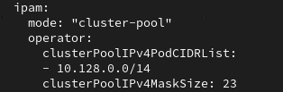
operator:
clusterPoolIPv4PodCIDRList:
- 10.128.0.0/14
clusterPoolIPv4MaskSize: 23
Step 7. If installing Isovalent Cilium in place of OVN networking, scroll down to find the kubeProxyReplacement: line, change the value to true and add the following two lines, substituting your api entry:
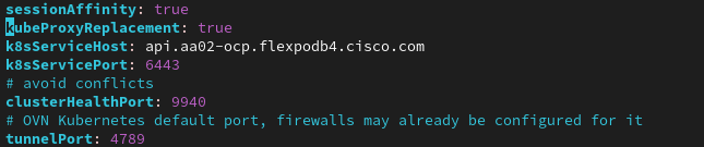
kubeProxyReplacement: true
k8sServiceHost: api.aa02-ocp.flexpodb4.cisco.com
k8sServicePort: 6443
Step 8. If installing Isovalent Cilium in place of OVN networking, add the following to the hubble: section to enable metrics:
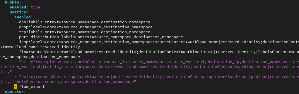
metrics:
enabled:
- dns:labelsContext=source_namespace,destination_namespace
- drop:labelsContext=source_namespace,destination_namespace
- tcp:labelsContext=source_namespace,destination_namespace
- port-distribution:labelsContext=source_namespace,destination_namespace
- icmp:labelsContext=source_namespace,destination_namespace;sourceContext=workload-name|reserved-identity;destinationContext=workload-name|reserved-identity
- flow:sourceContext=workload-name|reserved-identity;destinationContext=workload-name|reserved-identity;labelsContext=source_namespace,destination_namespace
- "httpV2:exemplars=true;labelsContext=source_ip,source_namespace,source_workload,destination_ip,destination_namespace,destination_workload,traffic_direction;sourceContext=workload-name|reserved-identity;destinationContext=workload-name|reserved-identity"
- "policy:sourceContext=app|workload-name|pod|reserved-identity;destinationContext=app|workload-name|pod|dns|reserved-identity;labelsContext=source_namespace,destination_namespace"
- flow_export
Step 9. If installing Isovalent Cilium in place of OVN networking, save cilliumconfig.yaml and open subscription.yaml. Add the following five lines starting with the config: line to the end of the file, substituting your API entry:
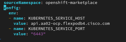
config:
env:
- name: KUBERNETES_SERVICE_HOST
value: api.aa02-ocp.flexpodb4.cisco.com
- name: KUBERNETES_SERVICE_PORT
value: "6443"
Step 10. If installing Isovalent Cilium in place of OVN networking, save the subscription.yaml file.
Step 11. Launch Microsoft Edge and connect to https://console.redhat.com/openshift/clusters/list. Log into your Red Hat account.
Step 12. Click Create cluster to create an OpenShift cluster.
Step 13. Select Datacenter and then select Bare Metal (x86_64).
Step 14. Select Interactive to launch the Assisted Installer.
Step 15. Provide the cluster name and base domain. Select the latest OpenShift 4.20 version. Scroll down and click Next.
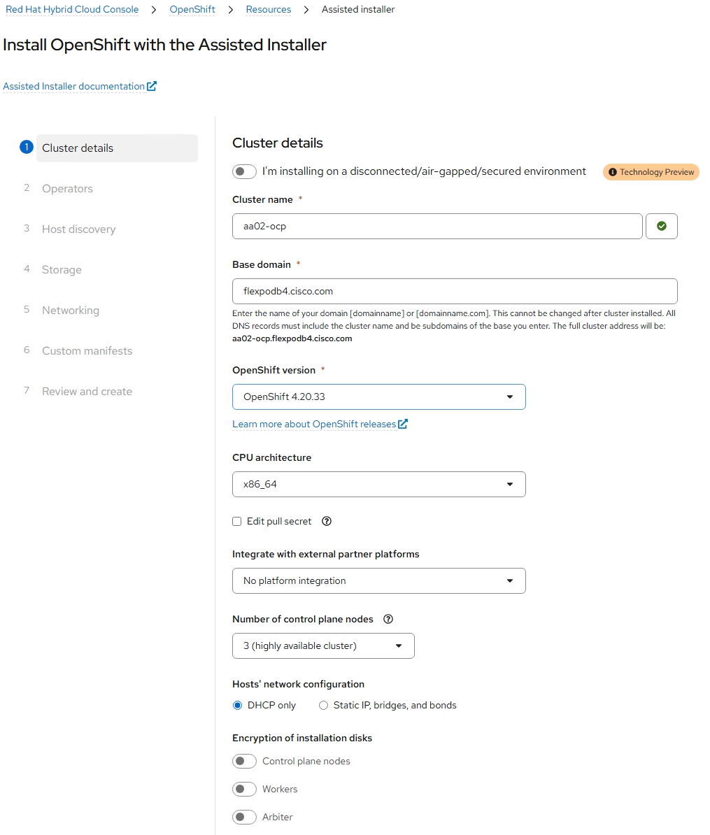
Step 16. It is not necessary to install any Operators at this time; they can be added later. Click Next.
Step 17. Click Add hosts.
Step 18. Under Provisioning type, from the drop-down list select either the Minimal or Full image file, depending on whether you have Intersight Advantage licenses and plan to use the Assisted Installer’s Intersight Integration or you plan to download the Discovery ISO to your network and will serve it on a local HTTP server. Under SSH public key, click Browse and browse to, select, and open the id_ed25519.pub file. The contents of the public key should now appear in the box. Click Generate Discovery ISO.
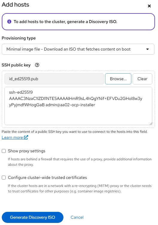
Step 19. If your Cisco UCS Servers have the Intersight Advantage license installed, click Add hosts from Cisco Intersight. If you do not have the Advantage license or you do not wish to use the Cisco Intersight Integration, skip to Step 23.
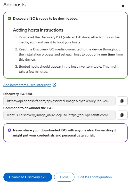
Step 20. A Cisco Intersight tab will appear in Edge. If you did not already have Intersight opened, log into Intersight and select the appropriate account. Select the appropriate Organization (AA02-OCP). Click Select Servers to select the servers for the OpenShift installation. In the list on the right, select the servers to install OpenShift onto and click Save. In the lower right-hand corner, click Execute. The Workflow will mount the Discovery ISO from the Red Hat Cloud and reboot the servers into the Discovery ISO.
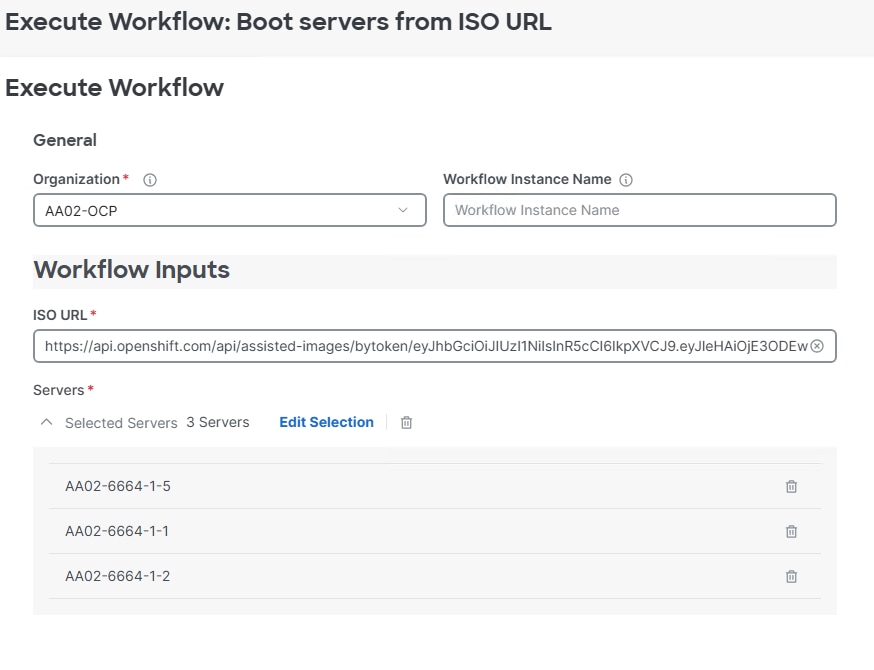
Note: At this point you are only going to install the three combination control plane / worker nodes. You will install the fourth node (worker-0) as an added server later.
Step 21. The workflow will mount the Discovery ISO on all hosts and reboot the hosts into Red Hat CoreOS. When the CoreOS boot is completed, the hosts will connect to and appear in the Assisted Installer.
Step 22. Back in the Red Hat Hybrid Cloud Console, click Close to close the Add hosts popup. Note that it will take several minutes for CoreOS boot to complete. Skip to Step 30 below.
Step 23. Click Download Discovery ISO to download the Discovery ISO into the Downloads directory. Click Close when the download is done.
Step 24. Copy the Discovery ISO to an http server. Use a web browser to get a copy of the URL for the Discovery ISO.
Step 25. Use Edge to connect to Cisco Intersight and log into the Intersight account previously set up.
Step 26. Go to Configure > Policies and edit the Virtual Media policy attached to your OpenShift server profiles. Once on the Policy Details page, click Add Virtual Media.
Step 27. In the Add Virtual Media dialogue, leave CDD selected and select HTTP/HTTPS. Provide a name for the mount and add the URL for File Location.
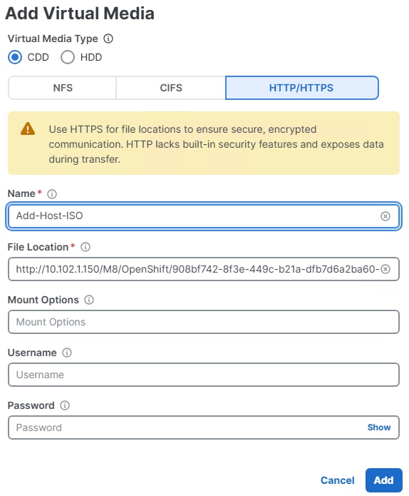
Step 28. Click Add. Click Save & Deploy then click Save & Proceed. It is not necessary to reboot the hosts to add the vMedia mount. Click Deploy. Wait for each of the servers to complete deploying the profile.
Step 29. Go to Configure > Profiles > UCS Server Profiles. Once all server profiles have a status of OK, click the … to the right of each profile and select Server Actions > Power > Power Cycle then Power Cycle to reboot each of the servers. If the M.2 drives are blank, the servers should boot from the Discovery ISO. This can be monitored with the vKVM if desired.
Step 30. Once all of the servers have booted RHEL CoreOS (Live) from the Discovery ISO, they will appear in the Assisted Installer under Host discovery. Use the drop-down lists under Role to assign the appropriate server roles. Scroll down and click Next.
Note: If using combined control-plane and worker nodes, enable Run workloads on control plane nodes. When the Control pane node role is selected, it will also include the Worker role.
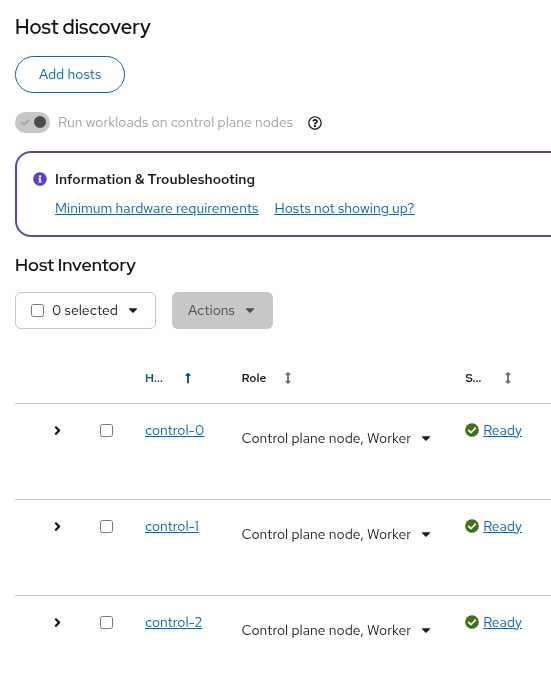
Step 31. Expand each node and verify CoreOS and OpenShift is being installed to the CISCO_VD device. Click Next.
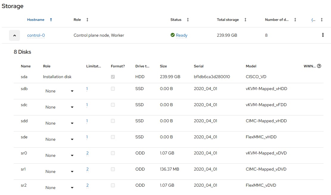
Step 32. Under Networking, make sure Cluster-Managed Networking is selected. Under Network type, if installing Isovalent Cilium, use the pulldown to select Isovalent Cilium. Under Machine network, from the drop-down list select the subnet for the BareMetal VLAN. Enter the API IP for the api.cluster.basedomain entry in the DNS servers. For the Ingress IP, enter the IP for the *.apps.cluster.basedomain entry in the DNS servers.
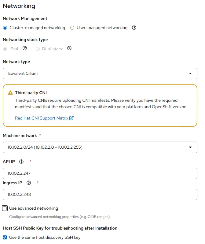
Step 33. Scroll down. If the nodes have the Insufficient Status, go to Intersight and select Operate > Servers. Select an OpenShift node server and go to Inventory > Network Adapters > VIC Adapter. Select the Interfaces tab. Click the ellipses to Disable interface eno9.
Step 34. Repeat this procedure for eno9 on all nodes. All nodes should then have a status of Ready. Click Next.
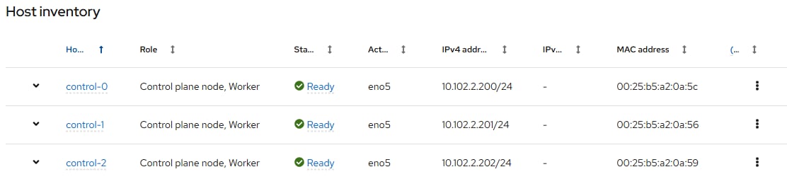
Step 35. If installing Isovalent Cilium, on the Custom manifests page, you will need to upload all 18 custom manifest files downloaded earlier, including the two that were modified. Leave manifests selected as the folder and upload Custom manifest 1 through Custom manifest 18, making sure to upload a unique file for each manifest. Click Next.
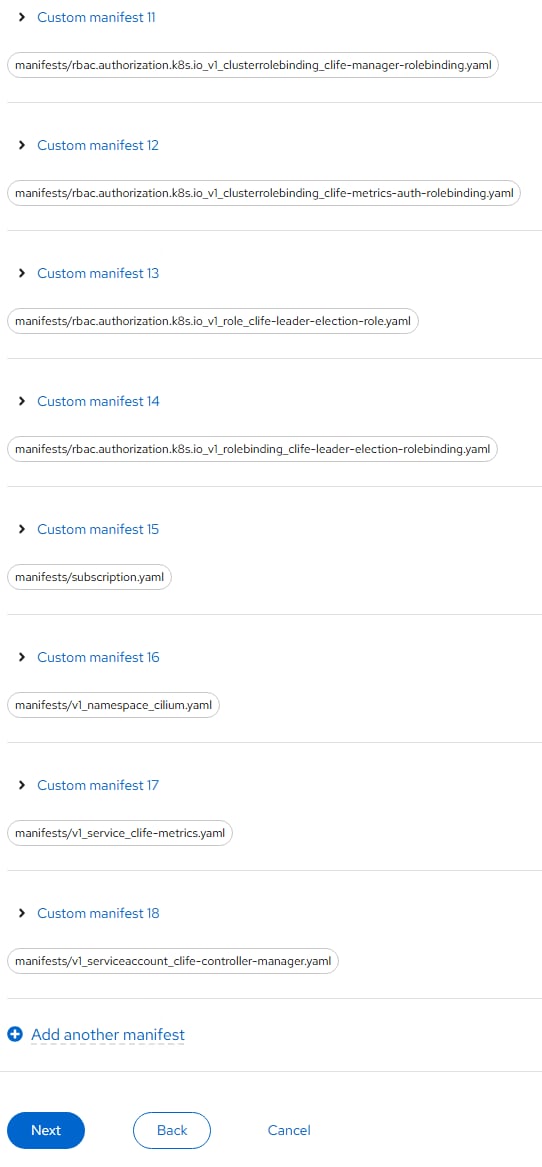
Step 36. Review the information and scroll down and click Install cluster to begin the cluster installation.
Step 37. On the Installation progress page, expand the Host inventory. The installation will take 30-45 minutes. When installation is complete, all nodes will show a Status of Installed.
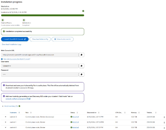
Step 38. Select Download kubeconfig to download the kubeconfig file. In a terminal window, setup a directory and save credentials:
cd ~/<clustername>
mkdir auth
cd auth
mv ~/Downloads/kubeconfig ./
mkdir ~/.kube
cp kubeconfig ~/.kube/config
Step 39. In the Assisted Installer, click the icon to copy the kubeadmin password:
echo <paste password> > ./kubeadmin-password
cat kubeadmin-password
Step 40. In a new tab in Chrome, connect to https://access.redhat.com/downloads/content/290. Download the OpenShift Linux Client for the version of OpenShift that you installed:
cd ..
mkdir client
cd client
ls ~/Downloads
mv ~/Downloads/openshift-client-linux-amd64-rhel9-x.xx.xx.tar.gz ./
tar xzvf openshift-client-linux-amd64-rhel9-x.xx.xx.tar.gz
ls
sudo mv oc /usr/local/bin/
sudo mv kubectl /usr/local/bin/
oc get nodes
Step 41. To enable oc tab completion for bash, run the following:
oc completion bash > oc_bash_completion
sudo mv oc_bash_completion /etc/bash_completion.d/
Step 42. If Isovalent Cilium was installed, download and install the cilium cli command and check cilium status:
CILIUM_CLI_VERSION=$(curl -s https://raw.githubusercontent.com/cilium/cilium-cli/main/stable.txt)
curl -L --fail --remote-name-all https://github.com/cilium/cilium-cli/releases/download/${CILIUM_CLI_VERSION}/cilium-linux-amd64.tar.gz
tar xzvf cilium-linux-amd64.tar.gz
sudo mv cilium /usr/local/bin/
cilium -n cilium status
/¯¯\
/¯¯\__/¯¯\ Cilium: OK
\__/¯¯\__/ Operator: OK
/¯¯\__/¯¯\ Envoy DaemonSet: OK
\__/¯¯\__/ Hubble Relay: disabled
\__/ ClusterMesh: disabled
DaemonSet cilium Desired: 3, Ready: 3/3, Available: 3/3
DaemonSet cilium-envoy Desired: 3, Ready: 3/3, Available: 3/3
Deployment cilium-operator Desired: 2, Ready: 2/2, Available: 2/2
Containers: cilium Running: 3
cilium-envoy Running: 3
cilium-operator Running: 2
clustermesh-apiserver
hubble-relay
Cluster Pods: 115/115 managed by Cilium
Helm chart version:
Image versions cilium quay.io/isovalent/cilium-ubi:v1.18.11-cee.1@sha256:0dd0fbaad763d0a78d1151e3c4deb4942b6fb43dc87285a911480845954827e5: 3
cilium-envoy quay.io/isovalent/cilium-envoy-ubi:v1.18.11-cee.1@sha256:ef4fe3701412aa2f01705bb5e9a545424cb5ee9b5aa93df3e643738873c97d28: 3
cilium-operator quay.io/isovalent/operator-generic-ubi:v1.18.11-cee.1@sha256:55f65095c81baa79bd339d9d7a29686e7c818f02f8abca1c04f2fa21d251e289: 2
Step 43. Set Cilium to be automatically upgraded to the latest release:
oc get installplan -n cilium
NAME CSV APPROVAL APPROVED
install-5kshq clife.v1.18.11-cee.1 Manual false
oc patch installplan install-5kshq -n cilium --type merge --patch '{"spec":{"approved":true}}'
installplan.operators.coreos.com/install-5kshq patched
Step 44. If you used the Cisco UCS Integration in the OpenShift installation process, connect to Cisco Intersight and from Configure > Profiles > UCS Server Profiles, select all OpenShift Server Profiles. Use the More actions pulldown and select Deploy. It is not necessary to reboot the servers, only select the lower check box and click Deploy.
Step 45. If you did not use the Cisco UCS Integration in the OpenShift installation process, in Cisco Intersight, edit the Virtual Media policy and remove the link to the Discovery ISO. Click Save & Deploy and then click Save & Proceed. Do not select Reboot Immediately to Activate. Click Deploy. The virtual media mount will be removed from the servers without rebooting them.
Step 46. In Cisco Intersight, select Operate > Servers. Select an OpenShift node server and then Inventory > Network Adapters > VIC Adapter. Select the Interfaces tab. Use the ellipses to the right of eno9 to Enable that interface. Repeat this process for eno9 on all nodes.
Step 47. Using Edge, in the Assisted Installer page, click Open console to launch the OpenShift Console. Use kubeadmin and the kubeadmin password to login. Click Skip tour. On the left, go to Compute > Nodes to see the status of the OpenShift nodes.
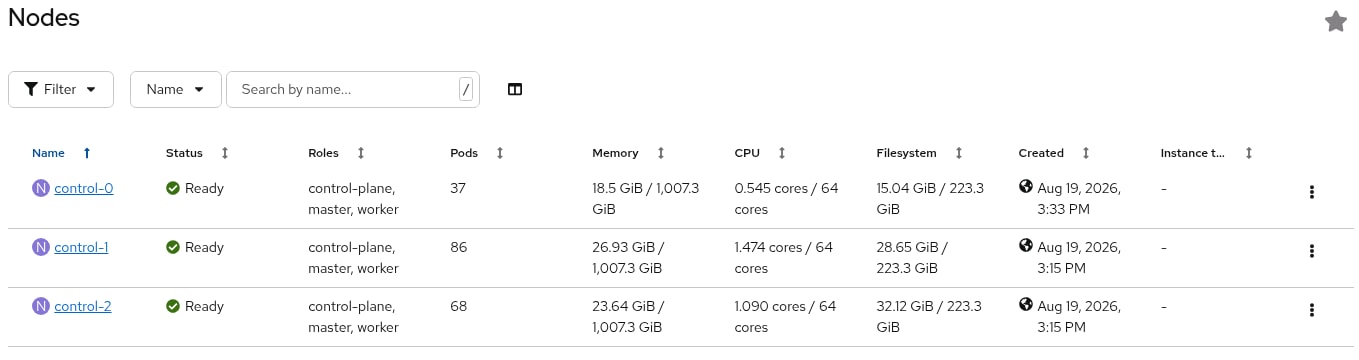
Step 48. In the Red Hat OpenShift console, go to Administration > Cluster Settings > Configuration > Network operator.openshift.io > YAML. Under spec:, change the deployKubeProxy field value to false. Click Save.
Procedure 3. Configure OpenShift
Step 1. In the Red Hat OpenShift console, go to Compute > Bare Metal Hosts. Select the All Projects Project. For each Bare Metal Host, highlight and copy the serial number. Click the ellipses to the right of the host and select Edit Bare Metal Host. Select Enable power management. Using Table 11, for a supported redfish connection to the server, use redfish-virtualmedia://<BMC IP>/redfish/v1/Systems/<server Serial Number> and make sure to check Disable Certificate Verification. Also, make sure the Boot MAC Address matches the MAC address in Table 11. For the BMC Username and BMC Password, use what was entered into the Cisco Intersight Local User policy. Click Save to save the changes. Repeat this step for all Bare Metal Hosts.
Note: When using redfish-virtualmedia to connect to the server, it is critical to check the box Disable Certificate Verification.
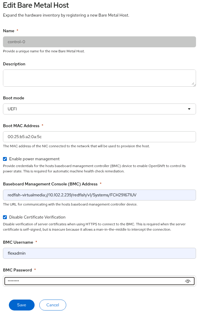
Step 2. If there is an issue with the Bare Metal Host setup, the host can be detached to edit the Bare Metal Host. To detach a host from the Installer workstation, run the following commands:
oc project openshift-machine-api
oc annotate bmh <bmh-name> -n openshift-machine-api baremetalhost.metal3.io/detached=""
Step 3. If there is an issue with a Bare Metal Host, select the Bare Metal Host in the OpenShift console and select the YAML tab. You can now make changes to the spec: fields and click Save to save. Once all changes have been made, delete the detached annotation line and click Save.
Step 4. Go to Compute > Bare Metal Hosts. Once all hosts have been configured, the Status should show Externally provisioned, and the Management Address should be populated. You can now manage power on the OpenShift hosts from the OpenShift console.
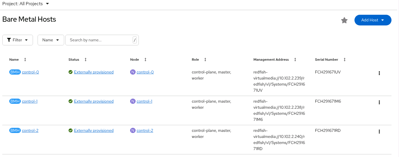
Step 5. If you are configuring NVMe-TCP storage, set a unique NVMe NQN on each node with the worker role, including combination control-plane and worker nodes. For each node with the worker role (this example is for worker-0) from the installer VM:
ssh core@worker-0
cat /etc/nvme/hostnqn
sudo nvme gen-hostnqn | sudo tee /etc/nvme/hostnqn
cat /etc/nvme/hostnqn
exit
Step 6. Enable dynamic resource allocation for kubelet. On your installer VM, create a directory for resource allocation, place the following YAML files in it, and run the commands to create the configuration:
cat worker-kubeletconfig.yaml
apiVersion: machineconfiguration.openshift.io/v1
kind: KubeletConfig
metadata:
name: dynamic-node
spec:
autoSizingReserved: true
machineConfigPoolSelector:
matchLabels:
pools.operator.machineconfiguration.openshift.io/worker: ""
cat control-plane-kubeletconfig.yaml
apiVersion: machineconfiguration.openshift.io/v1
kind: KubeletConfig
metadata:
name: dynamic-node-control-plane
spec:
autoSizingReserved: true
machineConfigPoolSelector:
matchLabels:
pools.operator.machineconfiguration.openshift.io/master: ""
oc create -f worker-kubeletconfig.yaml
oc create -f control-plane-kubeletconfig.yaml
Step 7. To setup NTP on the worker and control-plane nodes, and NVMe-TCP on the worker nodes, run the following:
sudo dnf install butane
cd
cd <cluster-name> # For example, ocp
mkdir machine-configs
cd machine-configs
Step 8. Build the following files in the machine-configs directory with variations for your network:
cat 99-control-plane-chrony-conf-override.bu
variant: openshift
version: 4.20.0
metadata:
name: 99-control-plane-chrony-conf-override
labels:
machineconfiguration.openshift.io/role: master
storage:
files:
- path: /etc/chrony.conf
mode: 0644
overwrite: true
contents:
inline: |
driftfile /var/lib/chrony/drift
makestep 1.0 3
rtcsync
logdir /var/log/chrony
server 10.102.2.3 iburst
server 10.102.2.4 iburst
cat 99-worker-chrony-conf-override.bu
variant: openshift
version: 4.20.0
metadata:
name: 99-worker-chrony-conf-override
labels:
machineconfiguration.openshift.io/role: worker
storage:
files:
- path: /etc/chrony.conf
mode: 0644
overwrite: true
contents:
inline: |
driftfile /var/lib/chrony/drift
makestep 1.0 3
rtcsync
logdir /var/log/chrony
server 10.102.2.3 iburst
server 10.102.2.4 iburst
cat 99-worker-nvme-discovery.bu
variant: openshift
version: 4.20.0
metadata:
name: 99-worker-nvme-discovery
labels:
machineconfiguration.openshift.io/role: worker
openshift:
kernel_arguments:
- loglevel=7
storage:
files:
- path: /etc/nvme/discovery.conf
mode: 0644
overwrite: true
contents:
inline: |
--transport=tcp --traddr=192.168.32.51 --trsvcid=8009
--transport=tcp --traddr=192.168.32.52 --trsvcid=8009
--transport=tcp --traddr=192.168.42.51 --trsvcid=8009
--transport=tcp --traddr=192.168.42.52 --trsvcid=8009
Step 9. Create .yaml files from the butane files with butane, then load the configurations into OpenShift:
butane 99-control-plane-chrony-conf-override.bu -o ./99-control-plane-chrony-conf-override.yaml
butane 99-worker-chrony-conf-override.bu -o ./99-worker-chrony-conf-override.yaml
butane 99-worker-nvme-discovery.bu -o ./99-worker-nvme-discovery.yaml
oc create -f 99-control-plane-chrony-conf-override.yaml
oc create -f 99-worker-chrony-conf-override.yaml
oc create -f 99-worker-nvme-discovery.yaml
Note: If using combined control-plane and worker nodes, 99-control-plane-nvme-discovery.bu and 99-control-plane-nmve-discovery.yaml files will need to be created and loaded into OpenShift.
Step 10. To set the local timezone in the OpenShift hosts, create 99-control-plane-set-timezone.yaml and 99-worker-set-timezone.yaml, substituting your local timezone and upload as machine configs.
cat 99-control-plane-set-timezone.yaml
apiVersion: machineconfiguration.openshift.io/v1
kind: MachineConfig
metadata:
labels:
machineconfiguration.openshift.io/role: master
name: 99-control-plane-set-timezone
spec:
config:
ignition:
version: 3.2.0
systemd:
units:
- name: set-timezone.service
enabled: true
contents: |
[Unit]
Description=Set the system timezone
[Service]
Type=oneshot
ExecStart=/usr/bin/timedatectl set-timezone America/New_York
[Install]
WantedBy=multi-user.target
cat 99-worker-set-timezone.yaml
apiVersion: machineconfiguration.openshift.io/v1
kind: MachineConfig
metadata:
labels:
machineconfiguration.openshift.io/role: worker
name: 99-worker-set-timezone
spec:
config:
ignition:
version: 3.2.0
systemd:
units:
- name: set-timezone.service
enabled: true
contents: |
[Unit]
Description=Set the system timezone
[Service]
Type=oneshot
ExecStart=/usr/bin/timedatectl set-timezone America/New_York
[Install]
WantedBy=multi-user.target
oc create -f 99-control-plane-set-timezone.yaml
oc create -f 99-worker-set-timezone.yaml
Step 11. Set a password to log into only the vKVM console with the core user for troubleshooting purposes.
sudo dnf install mkpasswd
mkpasswd -m sha-512 <password>
$6$wFDXMWfn8JRdpVdl$v4MOWUpCL32AXNfyiiKJaHd..tiTclIUOnYfTrws5eUwmlsOxXnZcKMvNBCir70bWPxzaW3yp6oP7OtmIGJMz0
cat 99-control-plane-core-password.yaml
apiVersion: machineconfiguration.openshift.io/v1
kind: MachineConfig
metadata:
labels:
machineconfiguration.openshift.io/role: master
name: 99-control-plane-set-core-user-password
spec:
config:
ignition:
version: 3.4.0
passwd:
users:
- name: core
passwordHash: $6$wFDXMWfn8JRdpVdl$v4MOWUpCL32AXNfyiiKJaHd..tiTclIUOnYfTrws5eUwmlsOxXnZcKMvNBCir70bWPxzaW3yp6oP7OtmIGJMz0
cat 99-worker-core-password.yaml
apiVersion: machineconfiguration.openshift.io/v1
kind: MachineConfig
metadata:
labels:
machineconfiguration.openshift.io/role: worker
name: 99-worker-set-core-user-password
spec:
config:
ignition:
version: 3.4.0
passwd:
users:
- name: core
passwordHash: $6$wFDXMWfn8JRdpVdl$v4MOWUpCL32AXNfyiiKJaHd..tiTclIUOnYfTrws5eUwmlsOxXnZcKMvNBCir70bWPxzaW3yp6oP7OtmIGJMz0
oc create -f 99-control-plane-core-password.yaml
oc create -f 99-worker-core-password.yaml
Step 12. To configure iSCSI and multipathing on all servers, create 99-worker-ontap-iscsi.yaml and 99-control-plane-ontap-iscsi.yaml (if using combined control plane / worker nodes) and upload as a machine config:
cat 99-worker-ontap-iscsi.yaml
apiVersion: machineconfiguration.openshift.io/v1
kind: MachineConfig
metadata:
name: 99-worker-ontap-iscsi
labels:
machineconfiguration.openshift.io/role: worker
spec:
config:
ignition:
version: 3.2.0
storage:
files:
- contents:
source: data:text/plain;charset=utf-8;base64,IyBkZXZpY2UtbWFwcGVyLW11bHRpcGF0aCBjb25maWd1cmF0aW9uIGZpbGUKCiMgRm9yIGEgY29tcGxldGUgbGlzdCBvZiB0aGUgZGVmYXVsdCBjb25maWd1cmF0aW9uIHZhbHVlcywgcnVuIGVpdGhlcjoKIyAjIG11bHRpcGF0aCAtdAojIG9yCiMgIyBtdWx0aXBhdGhkIHNob3cgY29uZmlnCgojIEZvciBhIGxpc3Qgb2YgY29uZmlndXJhdGlvbiBvcHRpb25zIHdpdGggZGVzY3JpcHRpb25zLCBzZWUgdGhlCiMgbXVsdGlwYXRoLmNvbmYgbWFuIHBhZ2UuCgpkZWZhdWx0cyB7Cgl1c2VyX2ZyaWVuZGx5X25hbWVzIHllcwoJZmluZF9tdWx0aXBhdGhzIG5vCn0KCmJsYWNrbGlzdCB7CiAgICAgICBkZXZpY2UgewogICAgICAgICAgICAgICB2ZW5kb3IgIkFUQSIKICAgICAgICAgICAgICAgcHJvZHVjdCAiTWljcm9uXzUzMDBfTVRGRCIKICAgICAgIH0KfQo=
verification: {}
filesystem: root
mode: 600
overwrite: true
path: /etc/multipath.conf
systemd:
units:
- name: iscsid.service
enabled: true
state: started
- name: multipathd.service
enabled: true
state: started
osImageURL: ""
cat 99-control-plane-ontap-iscsi.yaml
apiVersion: machineconfiguration.openshift.io/v1
kind: MachineConfig
metadata:
name: 99-control-plane-ontap-iscsi
labels:
machineconfiguration.openshift.io/role: master
spec:
config:
ignition:
version: 3.2.0
storage:
files:
- contents:
source: data:text/plain;charset=utf-8;base64,IyBkZXZpY2UtbWFwcGVyLW11bHRpcGF0aCBjb25maWd1cmF0aW9uIGZpbGUKCiMgRm9yIGEgY29tcGxldGUgbGlzdCBvZiB0aGUgZGVmYXVsdCBjb25maWd1cmF0aW9uIHZhbHVlcywgcnVuIGVpdGhlcjoKIyAjIG11bHRpcGF0aCAtdAojIG9yCiMgIyBtdWx0aXBhdGhkIHNob3cgY29uZmlnCgojIEZvciBhIGxpc3Qgb2YgY29uZmlndXJhdGlvbiBvcHRpb25zIHdpdGggZGVzY3JpcHRpb25zLCBzZWUgdGhlCiMgbXVsdGlwYXRoLmNvbmYgbWFuIHBhZ2UuCgpkZWZhdWx0cyB7Cgl1c2VyX2ZyaWVuZGx5X25hbWVzIHllcwoJZmluZF9tdWx0aXBhdGhzIG5vCn0KCmJsYWNrbGlzdCB7CiAgICAgICBkZXZpY2UgewogICAgICAgICAgICAgICB2ZW5kb3IgIkFUQSIKICAgICAgICAgICAgICAgcHJvZHVjdCAiTWljcm9uXzUzMDBfTVRGRCIKICAgICAgIH0KfQo=
verification: {}
filesystem: root
mode: 600
overwrite: true
path: /etc/multipath.conf
systemd:
units:
- name: iscsid.service
enabled: true
state: started
- name: multipathd.service
enabled: true
state: started
osImageURL: ""
oc create -f 99-worker-ontap-iscsi.yaml
oc create -f 99-control-plane-ontap-iscsi.yaml
Note: If using combined control-plane and worker nodes, the 99-control-plane-ontap-iscsi.yaml file will need to be created and loaded into OpenShift.
Note: The Base 64 encoded source above is the following file (/etc/multipath.conf) encoded. It is necessary to set find_multipaths to no.
cat multipath.conf
# device-mapper-multipath configuration file
# For a complete list of the default configuration values, run either:
# # multipath -t
# or
# # multipathd show config
# For a list of configuration options with descriptions, see the
# multipath.conf man page.
defaults {
user_friendly_names yes
find_multipaths no
}
blacklist {
}
Step 13. If you are installing OpenShift Virtualization, enable Pressure Stall Information (PSI) on all nodes with the worker role:
cat 99-worker-enable-psi.yaml
apiVersion: machineconfiguration.openshift.io/v1
kind: MachineConfig
metadata:
labels:
machineconfiguration.openshift.io/role: worker
name: 99-worker-psi-karg
spec:
kernelArguments:
- psi=1
cat 99-control-plane-enable-psi.yaml # If using combination control plane / worker nodes
apiVersion: machineconfiguration.openshift.io/v1
kind: MachineConfig
metadata:
labels:
machineconfiguration.openshift.io/role: master
name: 99-control-plane-psi-karg
spec:
kernelArguments:
- psi=1
oc create -f 99-worker-enable-psi.yaml
oc create -f 99-control-plane-enable-psi.yaml
Step 14. If you are using GPUs in your environment, configure an Input Output Memory Management Unit (IOMMU) on each worker (100-worker-kernel-arg-iommu.yaml) and on control plane nodes (100-control-plane-kernel-arg-iommu.yaml) if using combination control plane / worker nodes with GPUs.
cat 100-worker-kernel-arg-iommu.yaml
apiVersion: machineconfiguration.openshift.io/v1
kind: MachineConfig
metadata:
labels:
machineconfiguration.openshift.io/role: worker
name: 100-worker-iommu
spec:
config:
ignition:
version: 3.2.0
kernelArguments:
- intel_iommu=on
- iommu=pt
cat 100-control-plane-kernel-arg-iommu.yaml
apiVersion: machineconfiguration.openshift.io/v1
kind: MachineConfig
metadata:
labels:
machineconfiguration.openshift.io/role: master
name: 100-control-plane-iommu
spec:
config:
ignition:
version: 3.2.0
kernelArguments:
- intel_iommu=on
- iommu=pt
oc create -f 100-worker-kernel-arg-iommu.yaml
oc create -f 100-control-plane-kernel-arg-iommu.yaml
Note: If your servers have AMD CPUs, replace “intel_iommu” with “amd_iommu.”
Step 15. Over the next 20-30 minutes each of the nodes will go through the Not Ready state and reboot. You can monitor this by going to Compute > MachineConfigPools in the OpenShift Console. Wait until both pools have an Update status of Up to date.
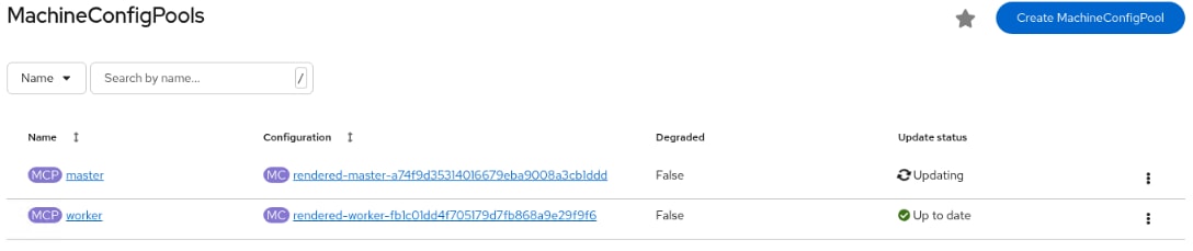
Note: Since we only have combo control plane / worker nodes, only the master pool will update. When worker-only nodes are added, those nodes will be in the worker MachineConfigPool.
Step 16. The Kubernetes NMState Operator will be used to configure the storage networking interfaces on the workers (and also virtual machine connected interfaces if OpenShift Virtualization is installed). In the OpenShift Console, go to Ecosystem > Software Catalog. In the search box, enter NMState and Kubernetes NMState Operator should appear. Click Kubernetes NMState Operator.
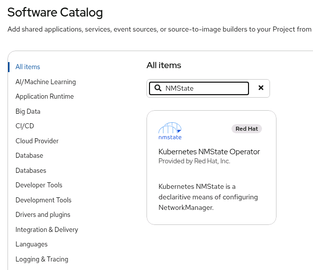
Step 17. Click Install. Leave all the defaults in place and click Install again. The operator will take a few minutes to install.
Step 18. Once the operator is installed, click View Operator.
Step 19. Select the NMState tab. On the right, click Create NMState. Leave all defaults in place and click Create. The nmstate will be created. You will also need to log into the console again because additional items will be added under Networking.
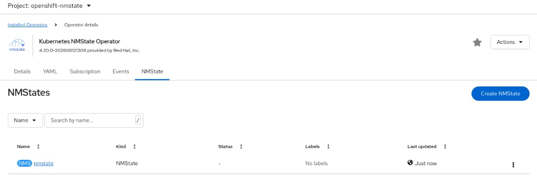
Step 20. In an NMState directory on the ocp-installer machine, create the following YAML files:
cat eno6.yaml
apiVersion: nmstate.io/v1
kind: NodeNetworkConfigurationPolicy
metadata:
name: ocp-eno6-policy
spec:
nodeSelector:
node-role.kubernetes.io/worker: ''
desiredState:
interfaces:
- name: eno6
description: Configuring eno6 on workers
type: ethernet
state: up
ipv4:
dhcp: true
enabled: true
ipv6:
enabled: false
cat eno6.3032.yaml # If configuring NVMe-TCP
apiVersion: nmstate.io/v1
kind: NodeNetworkConfigurationPolicy
metadata:
name: ocp-nvme-tcp-a-policy
spec:
nodeSelector:
node-role.kubernetes.io/worker: ''
desiredState:
interfaces:
- name: eno6.3032
description: VLAN 3032 using eno6
type: vlan
state: up
ipv4:
dhcp: true
enabled: true
ipv6:
enabled: false
vlan:
base-iface: eno6
id: 3032
cat eno7.yaml
apiVersion: nmstate.io/v1
kind: NodeNetworkConfigurationPolicy
metadata:
name: ocp-eno7-policy
spec:
nodeSelector:
node-role.kubernetes.io/worker: ''
desiredState:
interfaces:
- name: eno7
description: Configuring eno7 on workers
type: ethernet
state: up
ipv4:
dhcp: true
enabled: true
ipv6:
enabled: false
cat eno7.3042.yaml # If configuring NVMe-TCP
apiVersion: nmstate.io/v1
kind: NodeNetworkConfigurationPolicy
metadata:
name: ocp-nvme-tcp-b-policy
spec:
nodeSelector:
node-role.kubernetes.io/worker: ''
desiredState:
interfaces:
- name: eno7.3042
description: VLAN 3042 using eno7
type: vlan
state: up
ipv4:
dhcp: true
enabled: true
ipv6:
enabled: false
vlan:
base-iface: eno7
id: 3042
cat bond0.yaml
apiVersion: nmstate.io/v1
kind: NodeNetworkConfigurationPolicy
metadata:
name: bond0-ocp-nfs-vm-network
spec:
nodeSelector:
node-role.kubernetes.io/worker: ''
desiredState:
interfaces:
- name: bond0
description: Bond with ports eno8 and eno9
type: bond
state: up
ipv4:
dhcp: true # If configuring OpenShift Virtualization, set to false
enabled: true # If configuring OpenShift Virtualization, set to false
ipv6:
enabled: false
link-aggregation:
mode: balance-xor
options:
miimon: '100'
xmit_hash_policy: vlan+srcmac
balance-slb: 1
port:
- eno8
- eno9
mtu: 9000
cat bond0.3002.yaml
apiVersion: nmstate.io/v1
kind: NodeNetworkConfigurationPolicy
metadata:
name: ocp-live-migrate-policy
spec:
nodeSelector:
node-role.kubernetes.io/worker: ''
desiredState:
interfaces:
- name: bond0.3002
description: VLAN 3002 using bond0
type: vlan
state: up
ipv4:
dhcp: false
enabled: false
ipv6:
enabled: false
vlan:
base-iface: bond0
id: 3002
cat vm-network-bridge.yaml
apiVersion: nmstate.io/v1
kind: NodeNetworkConfigurationPolicy
metadata:
name: br-vm-network-policy
spec:
nodeSelector:
node-role.kubernetes.io/worker: ''
desiredState:
interfaces:
- name: br-vm-network
description: Linux bridge with bond0 as a port
type: linux-bridge
state: up
ipv4:
dhcp: true
enabled: true
ipv6:
enabled: false
bridge:
options:
stp:
enabled: false
port:
- name: bond0
Step 21. Add the Node Network Configuration Policies to the OpenShift cluster:
oc create -f eno6.yaml
oc create -f eno7.yaml
oc create -f eno6.3032.yaml # If configuring NVMe-TCP
oc create -f eno7.3042.yaml # If configuring NVMe-TCP
oc create -f bond0.yaml
oc create -f bond0.3002.yaml # If configuring OpenShift Virtualization
oc create -f vm-network-bridge.yaml # If configuring OpenShift Virtualization
Note: If you want to provide virtual machine in-guest NVMe-TCP, two NVMe-TCP bridges can be configured following the model of the vm-network-bridge. If these bridges are created, set the ipv4 dhcp and enabled parameters to false in both underlying VLAN interfaces.
Step 22. The policies appear under Networking > NodeNetworkConfigurationPolicy.
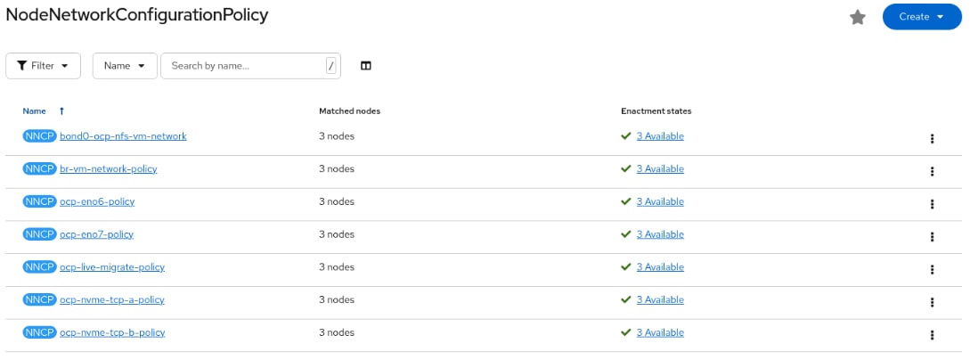
Note: If using combined control-plane and worker nodes, since all nodes have the worker role, the node selector will apply these policies to all nodes.
Step 23. Using ssh core@<node IP> or ssh core@<node_name>, connect to each of the worker nodes and use the ifconfig -a | more, chronyc sources, and timedatectl commands to verify the correct network and NTP setup of the servers.
Note: If your NVMe-TCP interfaces do not have IP addresses, back on the installer VM first drain the node by typing “oc adm drain <node_name>” followed by “ssh core@<node_name> sudo reboot”. When the node comes back up (check Compute > Nodes in the OpenShift console), type “oc adm uncordon <node_name>” to make the node schedulable. Make sure to reboot the nodes one at a time and that a node is schedulable before moving to the next node.
Procedure 4. Install the Cisco Intersight Plugin
The Cisco Intersight Plugin for Red Hat OpenShift natively integrates hardware management into the OpenShift console. It bridges applications and physical Cisco UCS servers, allowing administrators to monitor server health, security advisories, and firmware compatibility without switching contexts.
Step 1. In the OpenShift web console, click Ecosystem > Software Catalog.
Step 2. Type Intersight in the Filter box and then click Cisco Intersight with Certified in the upper right corner. Click Install.
Step 3. Change Console plugin to Enable and click Install.
Step 4. When the operator is installed, click Create CiscoIntersight.
Step 5. Select the checkbox for OsDiscoveryToolInstall and click Create.
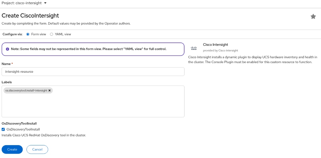
Step 6. On the left, select Cisco Intersight > Account Registration. Select the location where your Intersight account is located.
Step 7. Go to Cisco Intersight and connect to the account that contains this OpenShift installation. On the left, select Settings > OAuth2 Tokens. Click Create OAuth2.0. For App Name, enter the name of your OpenShift Cluster. For description, enter Intersight/OpenShift Integration. For Expiration Time, select something within your corporate Intersight policy limits. Click Create.
Step 8. Use the icon to copy the Client ID and paste it into the OpenShift console. Use the download icon to download and save the Client Secret. Copy and Paste Client Secret into the OpenShift console. In Intersight, select the I have downloaded the Client Secret checkbox and click Close.
Step 9. Back in the OpenShift console, click Test Connection. If the connection validates successfully, click Save Credentials. You can explore the Overview and Servers tabs to see what Intersight information is now available in the OpenShift console, including the ability to open vKVM consoles.
Step 10. Go to Intersight and select Operate > Servers. Select an OpenShift server and then select the HCL tab.
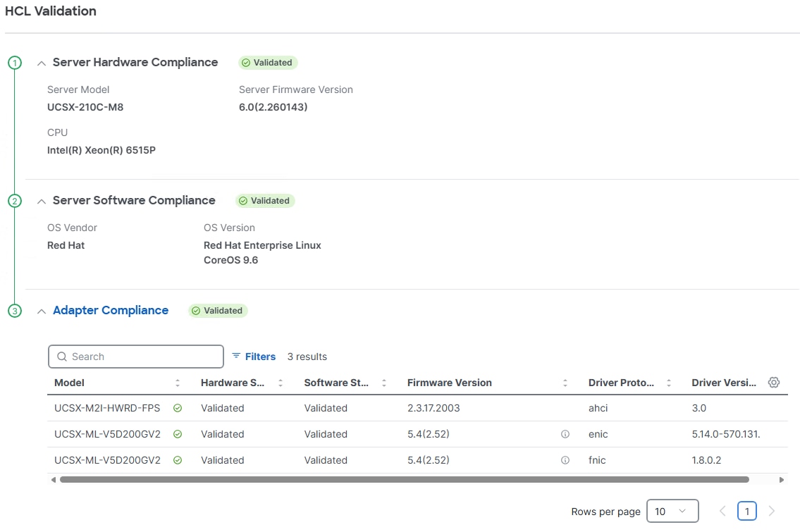
Note: At this time GPUs will not show Validated because the GPU driver is in a container and not directly visible in Red Hat CoreOS. Other hardware will show the validation status. This functionality is provided by the OSDiscovery Tool.
Step 11. The HCL validation is also shown in the Intersight plugin in the OpenShift console. In the OpenShift console, select Cisco Intersight > Servers. Select a server and then the HCL tab. Expand Adapter Compliance.
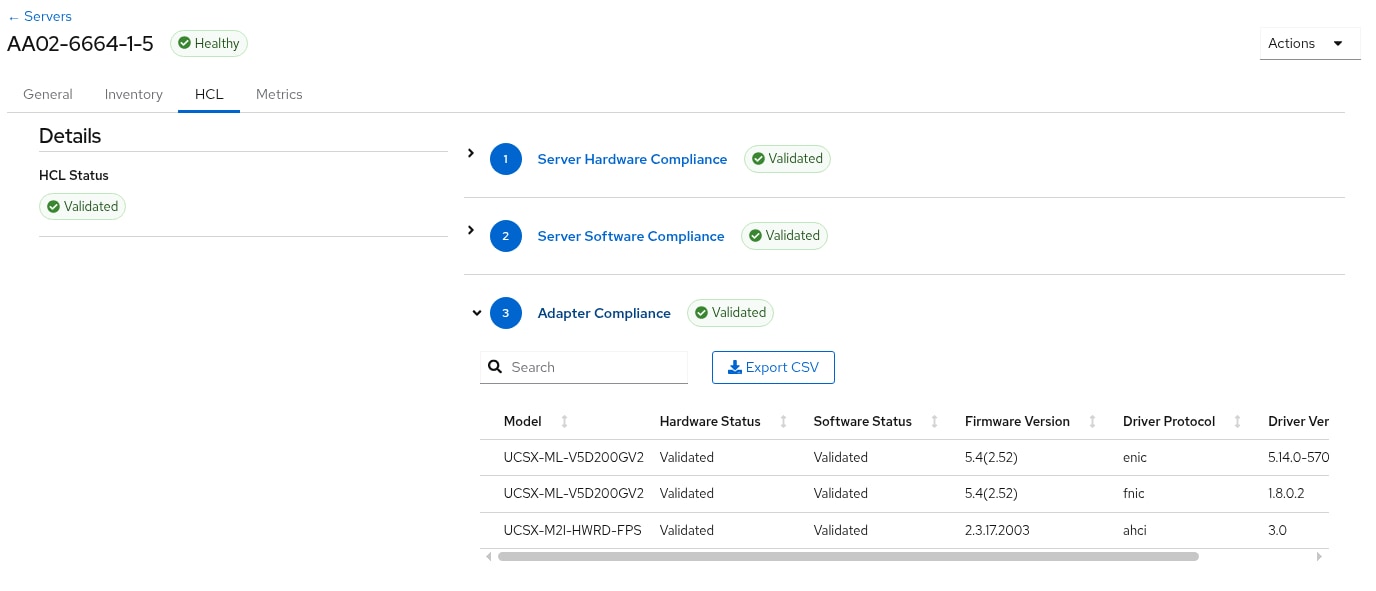
Step 12. Explore the tabs and the Actions pulldown menu to see what is provided by the OpenShift plugin in the OpenShift console.
Procedure 5. Install the NVIDIA GPU Operator (optional)
If you have GPUs installed in your Cisco UCS servers, you need to install the Node Feature Discovery (NFD) Operator to detect NVIDIA GPUs and the NVIDIA GPU Operator to make these GPUs available to containers and virtual machines.
Step 1. In the OpenShift web console, click Ecosystem > Software Catalog.
Step 2. Type Node Feature in the Filter box and then click the Node Feature Discovery Operator with Red Hat in the upper right corner. Click Install.
Step 3. Do not change any settings and click Install.
Step 4. When the Node Feature Discovery Operator is ready for use, click View Operator.
Step 5. In the bar to the right of Details, click NodeFeatureDiscovery.
Step 6. Click Create NodeFeatureDiscovery.
Step 7. Click Create.
Step 8. When the nfd-instance has a status of Available, Upgradeable, select Compute > Nodes.
Step 9. Select a node that has one or more GPUs and then select Details.
Step 10. The following label should be present on the host:

Note: This label should appear on all nodes with GPUs.
Step 11. Return to Ecosystem > Software Catalog.
Step 12. Type NVIDIA in the Filter box and then click the NVIDIA GPU Operator. Click Install.
Step 13. Do not change any settings and click Install.
Step 14. When the NVIDIA GPU Operator is ready for use, click View Operator.
Step 15. In the bar to the right of Details, click ClusterPolicy.
Step 16. Click Create ClusterPolicy.
Step 17. Connect to the Cisco UCS Hardware and Software Compatibility Tool. Change Search By: to Products. Then change Product Type: GPU. Search for the GPUs you have with the servers that you have and Red Hat Enterprise Linux 9.6. The result of the search shows driver series 595 at this time.
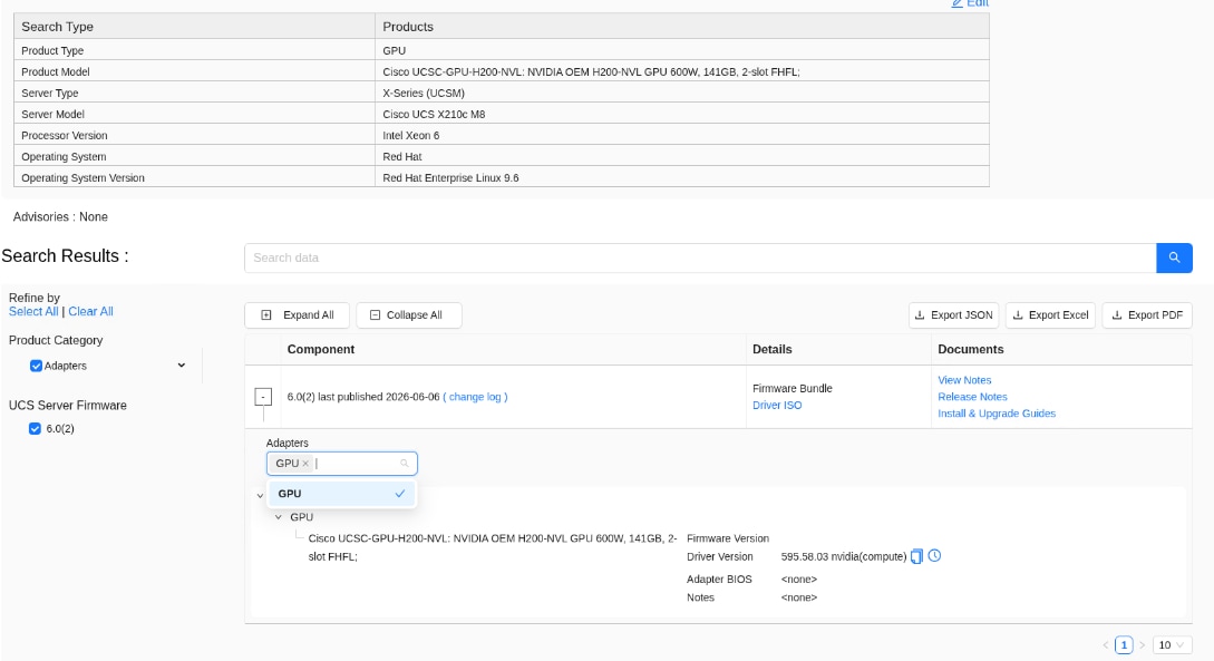
Note: Any later GPU driver in the same series listed on the Cisco UCS HCL is supported.
Step 18. Connect to https://ngc.nvidia.com. Search for and select NVIDIA GPU Driver. Select the Tags tab. For search within tags, enter rhel9.6. Currently, the latest driver in the 595 series is 595.91.07 and the tag is nvcr.io/nvidia/driver:595.91.07-rhel9.6.
Step 19. Back in the OpenShift console Create Cluster Policy page, expand NVIDIA GPU/vGPU Driver config. For repository, enter nvcr.io/nvidia. For version, enter 595.91.07 or the latest current version. For image, enter driver. Scroll down and click Create.
Step 20. Wait for the gpu-cluster-policy Status to become Ready.
Step 21. Connect to a terminal window on the OCP-Installer machine. Type the following commands. The output shown is for two servers that are equipped with GPUs:
oc project nvidia-gpu-operator
Now using project "nvidia-gpu-operator" on server "https://api.aa02-ocp.flexpodb4.cisco.com:6443".
oc get pods
NAME READY STATUS RESTARTS AGE
gpu-feature-discovery-cst9w 1/1 Running 0 4m33s
gpu-feature-discovery-zllw4 1/1 Running 0 4m37s
gpu-operator-9769d464b-j4np9 1/1 Running 0 10m
nvidia-container-toolkit-daemonset-4jkh2 1/1 Running 0 4m37s
nvidia-container-toolkit-daemonset-wxpg4 1/1 Running 0 4m33s
nvidia-cuda-validator-bjwbl 0/1 Completed 0 2m8s
nvidia-cuda-validator-dfmhl 0/1 Completed 0 2m4s
nvidia-dcgm-cl47k 1/1 Running 0 4m33s
nvidia-dcgm-exporter-4b8lr 0/1 Running 4 (60s ago) 4m37s
nvidia-dcgm-exporter-ptrdh 0/1 Running 4 (56s ago) 4m33s
nvidia-dcgm-lx6pl 1/1 Running 0 4m37s
nvidia-device-plugin-daemonset-8945v 1/1 Running 0 4m37s
nvidia-device-plugin-daemonset-npcbh 1/1 Running 0 4m33s
nvidia-driver-daemonset-9.6.20260727-0-52d6k 2/2 Running 0 4m45s
nvidia-driver-daemonset-9.6.20260727-0-9x6cm 2/2 Running 0 4m45s
nvidia-mig-manager-zw6qs 1/1 Running 0 66s
nvidia-node-status-exporter-fhggp 1/1 Running 0 4m42s
nvidia-node-status-exporter-sjr4w 1/1 Running 0 4m42s
nvidia-operator-validator-4vk5w 1/1 Running 0 4m33s
nvidia-operator-validator-szjkt 1/1 Running 0 4m37s
Step 22. Connect to one of the nvidia-driver-daemonset containers and view the GPU status:
oc exec -it nvidia-driver-daemonset-9.6.20260727-0-52d6k -- nvidia-smi
Thu Aug 13 20:45:10 2026
+-----------------------------------------------------------------------------------------+
| NVIDIA-SMI 595.71.05 Driver Version: 595.91.07 CUDA Version: 13.2 |
+-----------------------------------------+------------------------+----------------------+
| GPU Name Persistence-M | Bus-Id Disp.A | Volatile Uncorr. ECC |
| Fan Temp Perf Pwr:Usage/Cap | Memory-Usage | GPU-Util Compute M. |
| | | MIG M. |
|=========================================+========================+======================|
| 0 NVIDIA H200 NVL On | 00000000:48:00.0 Off | 0 |
| N/A 39C P0 73W / 600W | 0MiB / 143771MiB | 0% Default |
| | | Disabled |
+-----------------------------------------+------------------------+----------------------+
| 1 NVIDIA H200 NVL On | 00000000:49:00.0 Off | 0 |
| N/A 39C P0 71W / 600W | 0MiB / 143771MiB | 0% Default |
| | | Disabled |
+-----------------------------------------+------------------------+----------------------+
+-----------------------------------------------------------------------------------------+
| Processes: |
| GPU GI CI PID Type Process name GPU Memory |
| ID ID Usage |
|=========================================================================================|
| No running processes found |
+-----------------------------------------------------------------------------------------+
Procedure 6. Enable the GPU Monitoring Dashboard (Optional)
Step 1. Using https://docs.nvidia.com/datacenter/cloud-native/openshift/latest/enable-gpu-monitoring-dashboard.html, enable the GPU Monitoring Dashboard to monitor GPUs in the OpenShift Web-Console.
NetApp Trident is an open-source, fully supported storage orchestrator for containers and Kubernetes distributions. It was designed to help meet the containerized applications’ persistence demands using industry-standard interfaces, such as the Container Storage Interface (CSI). With Trident, microservices and containerized applications can take advantage of enterprise-class storage services provided by the NetApp portfolio of storage systems. More information about Trident can be found here: NetApp Trident Documentation. NetApp Trident can be installed via different methods. In this solution we will discuss installing the NetApp Trident version 26.6.0 using Trident Operator (installed using OperatorHub).
Trident Operator is a component used to manage the lifecycle of Trident. The operator simplifies the deployment, configuration, and management of Trident. The Trident operator is supported with OpenShift version 4.10 and above.
Note: In this solution, we validated NetApp Trident with the ontap-nas driver and ontap-nas-flexgroup driver using the NFS protocol. We also validated the ontap-san driver for iSCSI and NVMe-TCP protocols. Make sure to install only the backends and storage classes for the storage protocols you are using.
Procedure 1. Install the NetApp Trident Operator
In this implementation NetApp Trident Operator minimally version 26.6.1 is installed.
Step 1. In the OpenShift web console, click Ecosystem > Software Catalog.
Step 2. Type Trident in the Filter box and then click the Certified NetApp Trident operator. Click Install.
Step 3. Verify that at least Version 26.6.1 is selected. Click Install.
Step 4. Once the operator is installed and ready for use, click View Operator.
Step 5. In the bar to the right of Details, click Trident Orchestrator.
Step 6. Click Create TridentOrchestrator. Click Create. Wait for the Status to become Installed.
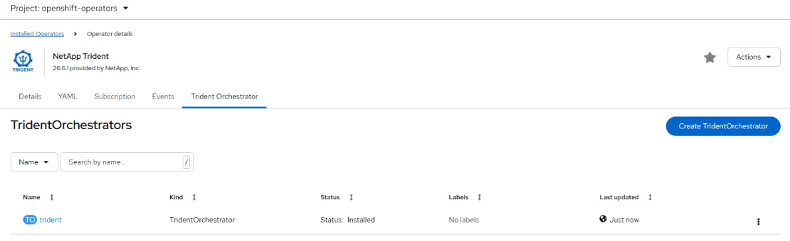
Step 7. On the installer VM, check the Trident OpenShift pods after installation:
oc get pods -n trident
NAME READY STATUS RESTARTS AGE
trident-controller-645bd744db-t9ml2 6/6 Running 0 81s
trident-node-linux-5sjj7 2/2 Running 0 81s
trident-node-linux-b7z85 2/2 Running 0 81s
trident-node-linux-khrrn 2/2 Running 0 81s
Procedure 2. Obtain tridentctl
Step 1. From the OpenShift directory, download Trident software from GitHub and untar the .gz file to obtain the trident-installer folder:
mkdir trident
cd trident
wget https://github.com/NetApp/trident/releases/download/v26.06.1/trident-installer-26.06.1.tar.gz
tar -xzvf trident-installer-26.06.1.tar.gz
Step 2. Copy tridentctl to /usr/local/bin:
sudo cp trident-installer/tridentctl /bin/
Note: If the NetApp Trident deployment fails and does not bring up the pods to Running state, use the tridentctl logs -l all -n trident command for debugging.
Note: Before configuring the backends that Trident needs to use for user apps, go to: https://docs.netapp.com/us-en/trident/trident-reference/objects.html#kubernetes-customresourcedefinition-objects to understand the storage environment parameters and its usage in Trident.
Step 3. Check the Trident version:
┌────────────────┬────────────────┐
│ SERVER VERSION │ CLIENT VERSION │
├────────────────┼────────────────┤
│ 26.06.1 │ 26.06.1 │
└────────────────┴────────────────┘
Procedure 3. Configure the Storage Backends in Trident
Step 1. Configure the connections to the SVM on the NetApp storage array created for the OpenShift installation. For more options regarding storage backend configuration, go to https://docs.netapp.com/us-en/trident/trident-use/backends.html.
Step 2. Create a backends directory and a secret for SVM access:
mkdir backends
cat backend-tbc-ontap-secret.yaml
apiVersion: v1
kind: Secret
metadata:
name: backend-tbc-ontap-secret
type: Opaque
stringData:
username: vsadmin
password: <password>
oc project trident
Now using project "trident" on server "https://api.aa02-ocp.flexpodb4.cisco.com:6443".
oc create -f backend-tbc-ontap-secret.yaml
Step 3. For NFS FlexGroup access, in your DNS server, ensure round-robin DNS is enabled and create two entries with the same hostname but different IP addresses matching your NFS LIF IPs. For example, the hostname could be aa02-ocp-nfs-lif with entries 192.168.52.51 and 192.168.52.52.
Step 4. Create the following backend definition files. Note that each backend definition includes a volume name template parameter that will give the volume configured on storage as part of the persistent volume a name that includes the backend name, the namespace, and the persistent volume claim (PVC) name (RequestName).
Note: Customizable volume names are compatible with ONTAP on-premises drivers only. Also, these volume names do not apply to existing volumes.
Note: In the following backend config definition files, we used StoragePrefix attribute under name template. The default value for StoragePrefix is trident.
apiVersion: trident.netapp.io/v1
kind: TridentBackendConfig
metadata:
name: backend-tbc-ontap-nfs-01
spec:
version: 1
storageDriverName: ontap-nas
managementLIF: 10.102.2.50
dataLIF: 192.168.52.51
backendName: tbc-ontap-nfs-01
svm: AA02-OCP-SVM
credentials:
name: backend-tbc-ontap-secret
aggregate: AA02_A90_01_NVME_SSD_1
useREST: true
defaults:
spaceReserve: none
exportPolicy: default
snapshotPolicy: default
snapshotReserve: '0'
nameTemplate: "{{.config.StoragePrefix}}_{{.config.BackendName}}_{{.volume.Namespace}}_{{.volume.RequestName}}"
cat backend_NFS_02.yaml
apiVersion: trident.netapp.io/v1
kind: TridentBackendConfig
metadata:
name: backend-tbc-ontap-nfs-02
spec:
version: 1
storageDriverName: ontap-nas
managementLIF: 10.102.2.50
dataLIF: 192.168.52.52
backendName: tbc-ontap-nfs-02
svm: AA02-OCP-SVM
credentials:
name: backend-tbc-ontap-secret
aggregate: AA02_A90_02_NVME_SSD_1
useREST: true
defaults:
spaceReserve: none
exportPolicy: default
snapshotPolicy: default
snapshotReserve: '0'
nameTemplate: "{{.config.StoragePrefix}}_{{.config.BackendName}}_{{.volume.Namespace}}_{{.volume.RequestName}}"
cat backend_NFS_flexgroup.yaml
apiVersion: trident.netapp.io/v1
kind: TridentBackendConfig
metadata:
name: backend-tbc-ontap-nfs-flexgroup
spec:
version: 1
storageDriverName: ontap-nas-flexgroup
managementLIF: 10.102.2.50
dataLIF: aa02-ocp-nfs-lif
backendName: tbc-ontap-nfs-flexgroup
svm: AA02-OCP-SVM
credentials:
name: backend-tbc-ontap-secret
useREST: true
defaults:
spaceReserve: none
exportPolicy: default
snapshotPolicy: default
snapshotReserve: '0'
nameTemplate: "{{.config.StoragePrefix}}_{{.config.BackendName}}_{{.volume.Namespace}}_{{.volume.RequestName}}"
cat backend_iSCSI.yaml
apiVersion: trident.netapp.io/v1
kind: TridentBackendConfig
metadata:
name: backend-tbc-ontap-iscsi
spec:
version: 1
storageDriverName: ontap-san
sanType: iscsi
managementLIF: 10.102.2.50
backendName: tbc-ontap-iscsi
svm: AA02-OCP-SVM
credentials:
name: backend-tbc-ontap-secret
useREST: true
defaults:
spaceReserve: none
spaceAllocation: 'false'
snapshotPolicy: default
snapshotReserve: '5'
nameTemplate: "{{.config.StoragePrefix}}_{{.config.BackendName}}_{{.volume.Namespace}}_{{.volume.RequestName}}"
cat backend_NVMe.yaml
apiVersion: trident.netapp.io/v1
kind: TridentBackendConfig
metadata:
name: backend-tbc-ontap-nvme-tcp
spec:
version: 1
storageDriverName: ontap-san
sanType: nvme
managementLIF: 10.102.2.50
backendName: tbc-ontap-nvme-tcp
svm: AA02-OCP-SVM
credentials:
name: backend-tbc-ontap-secret
useREST: true
defaults:
spaceReserve: none
snapshotPolicy: default
snapshotReserve: '5'
nameTemplate: "{{.config.StoragePrefix}}_{{.config.BackendName}}_{{.volume.Namespace}}_{{.volume.RequestName}}"
Step 5. Activate the storage backends for all storage protocols (NFS, iSCSI, and NVMe) in your FlexPod:
oc create -f backend_NFS_01.yaml
oc create -f backend_NFS_02.yaml
oc create -f backend_NFS_flexgroup.yaml
oc create -f backend_iSCSI.yaml
oc create -f backend_NVMe.yaml
oc get tbc
NAME BACKEND NAME BACKEND UUID PHASE STATUS
backend-tbc-ontap-iscsi tbc-ontap-iscsi 2715c650-8c2e-4276-b1a0-8fb813c284fa Bound Success
backend-tbc-ontap-nfs-01 tbc-ontap-nfs-01 52e5cdef-4ccf-41a5-878a-603a981bccf5 Bound Success
backend-tbc-ontap-nfs-02 tbc-ontap-nfs-02 a002147b-080d-4463-93d2-f5c27c0c38b7 Bound Success
backend-tbc-ontap-nfs-flexgroup tbc-ontap-nfs-flexgroup e8cf6bad-3ae6-481c-9fd1-fb92bf1865b7 Bound Success
backend-tbc-ontap-nvme-tcp tbc-ontap-nvme-tcp 98d3f0f1-5579-4dce-8cb0-df452e41c8cf Bound Success
tridentctl -n trident get backend
+-------------------------+---------------------+--------------------------------------+--------+------------+---------+
| NAME | STORAGE DRIVER | UUID | STATE | USER-STATE | VOLUMES |
+-------------------------+---------------------+--------------------------------------+--------+------------+---------+
| tbc-ontap-nfs-01 | ontap-nas | 52e5cdef-4ccf-41a5-878a-603a981bccf5 | online | normal | 0 |
| tbc-ontap-nfs-02 | ontap-nas | a002147b-080d-4463-93d2-f5c27c0c38b7 | online | normal | 0 |
| tbc-ontap-nfs-flexgroup | ontap-nas-flexgroup | e8cf6bad-3ae6-481c-9fd1-fb92bf1865b7 | online | normal | 0 |
| tbc-ontap-iscsi | ontap-san | 2715c650-8c2e-4276-b1a0-8fb813c284fa | online | normal | 0 |
| tbc-ontap-nvme-tcp | ontap-san | 98d3f0f1-5579-4dce-8cb0-df452e41c8cf | online | normal | 0 |
+-------------------------+---------------------+--------------------------------------+--------+------------+---------+
Step 6. Create the following Storage Class files:
cat storage-class-ontap-nfs.yaml
apiVersion: storage.k8s.io/v1
kind: StorageClass
metadata:
name: ontap-nfs
annotations:
storageclass.kubernetes.io/is-default-class: "true"
provisioner: csi.trident.netapp.io
parameters:
backendType: "ontap-nas"
provisioningType: "thin"
snapshots: "true"
mountOptions:
- vers=4.1
- nconnect=4
- rw
- hard
- proto=tcp
- timeo=600
allowVolumeExpansion: true
cat storage-class-ontap-nfs-flexgroup.yaml
apiVersion: storage.k8s.io/v1
kind: StorageClass
metadata:
name: ontap-nfs-flexgroup
annotations:
storageclass.kubernetes.io/is-default-class: "false"
provisioner: csi.trident.netapp.io
parameters:
backendType: "ontap-nas-flexgroup"
provisioningType: "thin"
snapshots: "true"
mountOptions:
- vers=4.1
- nconnect=4
- rw
- hard
- proto=tcp
- timeo=600
allowVolumeExpansion: true
cat storage-class-ontap-iscsi.yaml
apiVersion: storage.k8s.io/v1
kind: StorageClass
metadata:
name: ontap-iscsi
parameters:
backendType: "ontap-san"
sanType: "iscsi"
fsType: "xfs"
provisioningType: "thin"
snapshots: "true"
allowVolumeExpansion: true
provisioner: csi.trident.netapp.io
cat storage-class-ontap-nvme.yaml
apiVersion: storage.k8s.io/v1
kind: StorageClass
metadata:
name: ontap-nvme-tcp
parameters:
backendType: "ontap-san"
fsType: "xfs"
sanType: "nvme"
provisioningType: "thin"
snapshots: "true"
mountOptions:
- nouuid
allowVolumeExpansion: true
provisioner: csi.trident.netapp.io
Step 7. Create the storage classes:
oc create -f storage-class-ontap-nfs.yaml
oc create -f storage-class-ontap-nfs-flexgroup.yaml
oc create -f storage-class-ontap-iscsi.yaml
oc create -f storage-class-ontap-nvme.yaml
oc get sc
NAME PROVISIONER RECLAIMPOLICY VOLUMEBINDINGMODE ALLOWVOLUMEEXPANSION AGE
ontap-iscsi csi.trident.netapp.io Delete Immediate true 21s
ontap-nfs (default) csi.trident.netapp.io Delete Immediate true 50s
ontap-nfs-flexgroup csi.trident.netapp.io Delete Immediate true 40s
ontap-nvme-tcp csi.trident.netapp.io Delete Immediate true 8s
Step 8. Create a VolumeSnapshotClass file:
cat ontap-volumesnapshot-class.yaml
---
apiVersion: snapshot.storage.k8s.io/v1
kind: VolumeSnapshotClass
metadata:
name: ontap-snapclass
driver: csi.trident.netapp.io
deletionPolicy: Delete
Step 9. Create the VolumeSnapshotClass using the above file.
oc create -f ontap-volumesnapshot-class.yaml
Step 10. Create a test PersistentVolumeClaim (PVC). In the OpenShift console, click Storage > PersistentVolumeClaims. Select an appropriate project (for example, default) or create a new project and select it. On the right, click Create PersistentVolumeClaim.
Step 11. Select a StorageClass and give the PVC a name. Select an Access mode (RWO or RWX for NFS classes, and RWO for iSCSI or NVMe-TCP classes). Set a size and select a Volume mode (normally Filesystem). Click Create to create the PVC.
Note: For illustration, we created a test PVC using the ontap-nfs storage class.
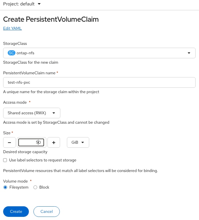
Step 12. Wait for the PVC to have a status of Bound. The PVC can now be attached to a container.
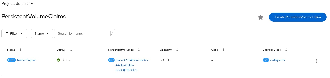
Step 13. Create a NetApp volume snapshot of the PVC by clicking the … to the right of the PVC and selecting Create snapshot. Adjust the snapshot name and click Create. The snapshot will appear under VolumeSnapshots and can also be seen in NetApp ONTAP System Manager under the corresponding PV with a modified name.
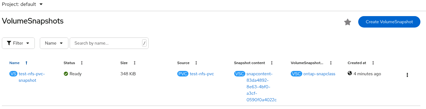
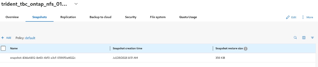
Note: Make sure the volume name for the PV matches the volume name mapping from the backend configuration in the above screenshot.
Step 14. Delete the test PVC and snapshot by first selecting the Snapshot under Storage > VolumeSnapshots and click the … to the right of the snapshot and select Delete VolumeSnapshot then click Delete. Select the PVC under Storage > PersistentVolumeClaims and click the … to the right of the PVC and select Delete PersistentVolumeClaim and click Delete.
Clone Volumes across Namespaces
In OpenShift environments, application and platform teams frequently need production-like data in a separate project for development, testing, or release validation—without disrupting the live workload or granting shared write access to the source volume. NetApp Trident supports cloning persistent volumes across namespaces, so a PVC in one project can be created from a volume or snapshot in another while the original application continues to run.
Because clones on ONTAP are typically thin and copy-on-write, they are available quickly and consume additional capacity only as data diverges—reducing provisioning time, lowering storage overhead versus full copies, and helping teams deliver safer, faster environment setup for day-2 operations.
Prerequisites
Before cloning volumes, ensure that the source and destination backends are of the same type and have the same storage class.
Note: Cloning across namespaces is supported only for the ontap-san and ontap-nas storage drivers. Read-only clones are not supported.
Procedure 1. Configure source PVC to clone the volume
Step 1. Create the source and destination namespaces:
oc create ns demo-src
oc create ns demo-dst
Step 2. Create the PVC (demo-pvc) in the source namespace (demo-src) that grants permission to share with the destination namespace (demo-dst) using the cloneToNamespace annotation:
cat src-pvc.yaml
---
kind: PersistentVolumeClaim
apiVersion: v1
metadata:
name: demo-pvc
namespace: demo-src
annotations:
trident.netapp.io/cloneToNamespace: demo-dst
spec:
accessModes:
- ReadWriteMany
storageClassName: ontap-nfs
resources:
requests:
storage: 100Gi
# Create PVC
oc create -f src-pvc.yaml
Note: You can share the PVC to multiple namespaces using a comma-delimited list. For example, trident.netapp.io/cloneToNamespace: namespace2,namespace3,namespace4.
Note: You can share to all namespaces using *. For example, trident.netapp.io/cloneToNamespace: *
Note: You can update the PVC to include the cloneToNamespace annotation at any time.
Step 3. Trident creates the PV and its backend storage volume as shown below.
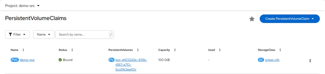
Step 4. Create a pod that mounts the source PVC:
cat src-pvc-test.yaml
---
apiVersion: v1
kind: Pod
metadata:
name: pvc-test
namespace: demo-src
spec:
containers:
- name: ubi
image: registry.access.redhat.com/ubi9/ubi-minimal
command:
- /bin/bash
- -c
- sleep infinity
volumeMounts:
- name: data-vol
mountPath: /data
volumes:
- name: data-vol
persistentVolumeClaim:
claimName: demo-pvc
# Create pod
oc create -f src-pvc-test.yaml
Step 5. Wait until the pod is running:
oc get pod pvc-test -n demo-src
NAME READY STATUS RESTARTS AGE
pvc-test 1/1 Running 1 10h
Step 6. Write data to the PVC. This step is required to validate data integrity once source PVC is cloned into destination namespace:
oc exec -it pvc-test -n demo-src -- sh
sh-5.1# cd /data
sh-5.1# echo "Hello Trident Clone Test" > /data/test.txt
sh-5.1# mkdir /data/sampledir
sh-5.1# echo "File 1" > /data/sampledir/file1.txt
sh-5.1# echo "File 2" > /data/sampledir/file2.txt
sh-5.1# dd if=/dev/urandom of=/data/random.bin bs=1M count=100
sh-5.1# ls -lah /data
total 101M
drwxrwxrwx. 4 99 99 4.0K Aug 11 09:23 .
dr-xr-xr-x. 1 root root 52 Aug 11 08:40 ..
-rw-r--r--. 1 99 99 100M Aug 11 09:23 random.bin
drwxr-xr-x. 2 99 99 4.0K Aug 11 09:23 sampledir
-rw-r--r--. 1 99 99 25 Aug 11 09:23 test.txt
Step 7. Generate checksums (recommended to perform before cloning):
sh-5.1# cd /data
# Generate a SHA256 manifest that excludes itself:
sh-5.1# find . -type f ! -name "checksums.sha256" -exec sha256sum {} \; > checksums.sha256
sh-5.1# sha256sum -c checksums.sha256
./test.txt: OK
./sampledir/file1.txt: OK
./sampledir/file2.txt: OK
./random.bin: OK
# Verify that all files show OK.
Procedure 2. Create TridentVolumeReference in the destination namespace
Step 1. Create a TridentVolumeReference CR in the destination namespace (demo-dst) that refers to the source PVC demo-pvc:
cat dst-tvr.yaml
---
apiVersion: trident.netapp.io/v1
kind: TridentVolumeReference
metadata:
name: dst-tvr
namespace: demo-dst
spec:
pvcName: demo-pvc
pvcNamespace: demo-src
# Create TridentVolumeReference
oc create -f dst-tvr.yaml
Note: Ensure that proper RBAC is in place to grant permission to the destination namespace owner to create the TridentVolumeReference CR in the destination namespace (demo-dst).
Step 2. TridentVolumeReference is created in the destination namespace:
oc get tvr -n demo-dst
NAME AGE
dst-tvr 60s
Procedure 3. Create the clone PVC in the destination namespace
Step 1. Create a PVC (demo-pvc-clone) in destination namespace (demo-dst) using the cloneFromPVC and cloneFromNamespace annotations to designate the source PVC (demo-pvc):
cat clone-from-pvc.yaml
---
kind: PersistentVolumeClaim
apiVersion: v1
metadata:
annotations:
trident.netapp.io/cloneFromPVC: demo-pvc
trident.netapp.io/cloneFromNamespace: demo-src
name: demo-pvc-clone
namespace: demo-dst
spec:
accessModes:
- ReadWriteMany
storageClassName: ontap-nfs
resources:
requests:
storage: 100Gi
# Create the clone PVC
oc create -f clone-from-pvc.yaml
Note: For PVCs provisioned using ontap-nas-economy drivers, read-only clones are not supported.
Step 2. Clone PVC (demo-pvc-clone) is created in the destination namespace as shown below.
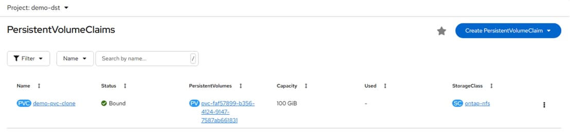
Procedure 4. Verify data integrity after cloning
Step 1. Mount the cloned PVC to another pod in destination namespace. Wait until the pod is running.
oc get pod clone-pvc-test -n demo-dst
NAME READY STATUS RESTARTS AGE
clone-pvc-test 1/1 Running 0 31s
Step 2. Exec into the destination pod (clone-pvc-test) and verify the file checksums to confirm the cloned data matches the source.
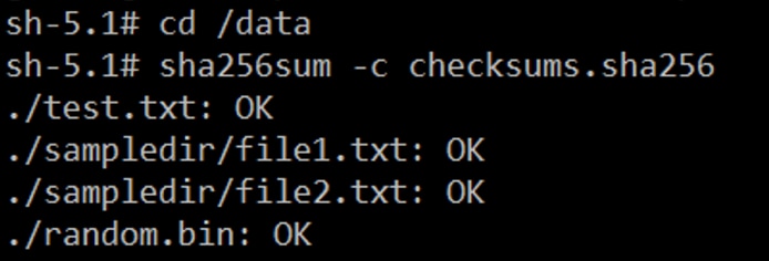
The checksum validation confirms that the destination PVC is a successful cross-namespace clone of the source volume, with data integrity preserved while the workloads remain isolated in their respective OpenShift projects.
The toolkit is currently compatible with Kubernetes versions 1.20 and above, and OpenShift versions 4.7 and above.
The toolkit is currently compatible with Trident versions 20.07 and above. Additionally, the toolkit is compatible with the following Trident backend types used in this validation:
● ontap-nas
● ontap-nas-flexgroup
More operations and capabilities about NetApp DataOps Toolkit are available and documented here: https://github.com/NetApp/netapp-dataops-toolkit
The NetApp DataOps Toolkit for Kubernetes requires that Python 3.8 or above be installed on the local host. Additionally, the toolkit requires that pip for Python3 be installed on the local host. For more details regarding pip, including installation instructions, see the pip documentation.
Procedure 1. NetApp DataOps Toolkit Installation
Step 1. To install the NetApp DataOps Toolkit for Kubernetes on the OCP-Installer VM, run the following command:
sudo dnf install python3.13
curl https://bootstrap.pypa.io/get-pip.py -o get-pip.py
python3.13 get-pip.py
rm get-pip.py
python3.13 -m pip install –-upgrade netapp-dataops-k8s
To verify:
netapp_dataops_k8s_cli.py version
NetApp DataOps Toolkit for Kubernetes - version 3.1.0
NetApp DataOps Toolkit is used to create jupyterlab, clone jupyterlab, create a snapshot for a JupyterLab workspace, and so on.
Note: You can use NetApp DataOps Toolkit to create Jupyter notebooks in this solution. For more information, go to: Create a new JupyterLab workspace.
Add an Additional Administrative User to the OpenShift Cluster
It is recommended to install a permanent administrative user to an OpenShift cluster to provide an alternative to logging in with the “temporary” kubeadmin user. This section shows how to build and install an HTPasswd user. Other Identity providers are also available.
Procedure 1. Add the admin User
Step 1. On the OCP-Installer VM in the auth directory where the kubeadmin-password and kubeconfig files are stored, create an admin.htpasswd file by typing:
htpasswd -c -B -b ./admin.htpasswd admin <password>
Adding password for user admin
Step 2. Using Edge on the OCP-Installer VM, connect to the OpenShift console with the kubeadmin user. In the blue banner near the top of the page, click cluster OAuth configuration.
Step 3. Use the Add drop-down under Identity providers to select HTPasswd. Click Browse and browse to the admin.htpasswd file created above. Highlight the file and click Select. Click Add. The htpasswd should now show up as an Identity provider.
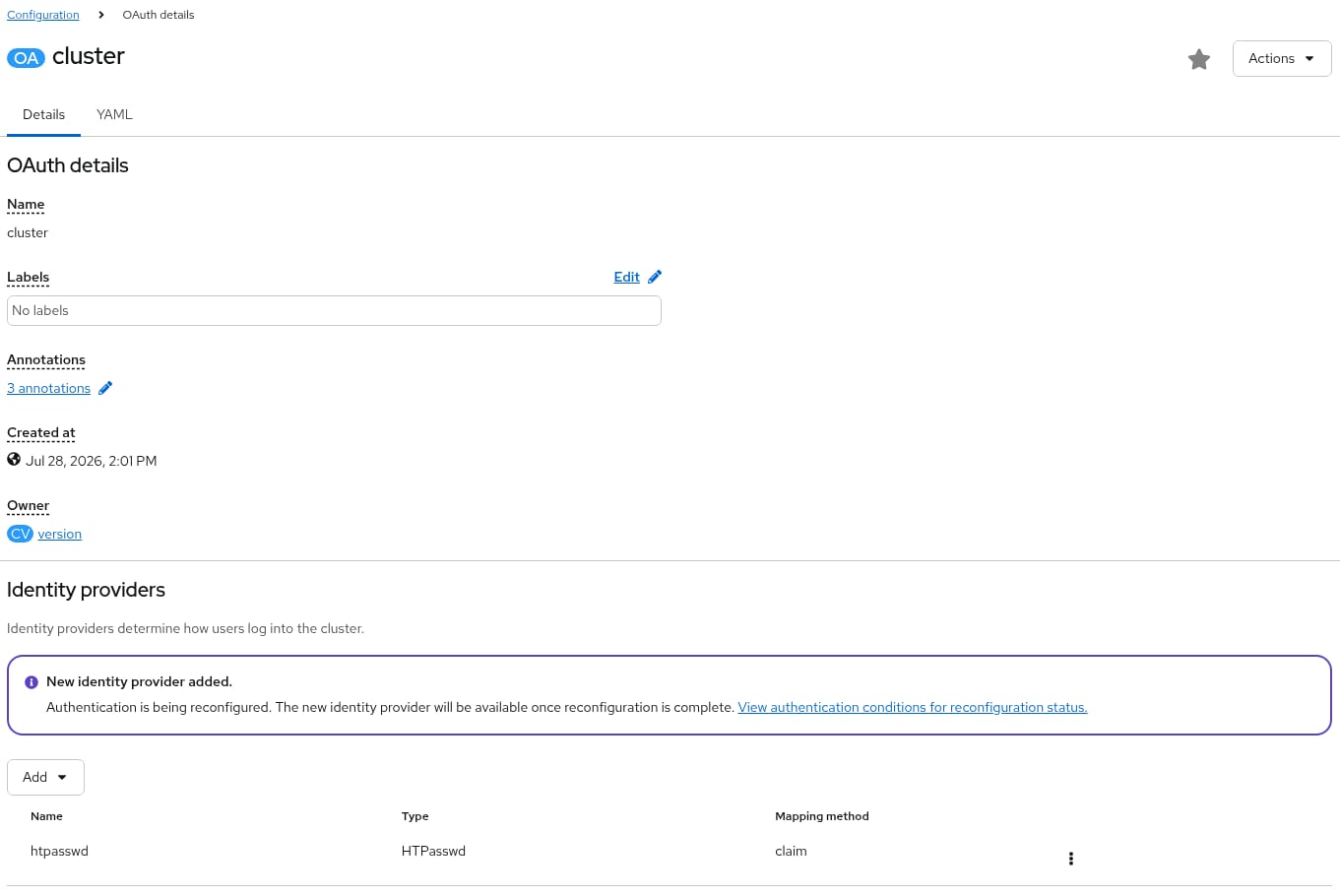
Step 4. Click View authentication conditions for the reconfiguration status and wait for the status to become Available.
Step 5. Log out of the cluster and log back in with htpasswd and the admin user. Click Skip tour and log out of the cluster.
Step 6. Log back into the cluster with kube:admin and the kubeadmin user. Select User Management > Users, then select the admin user. Select the RoleBindings tab and click Create binding.
Step 7. Select for a Cluster-wide role binding and name the RoleBinding admin-cluster-admin. From the drop-down list under Role name, select the cluster-admin role. Click Create.
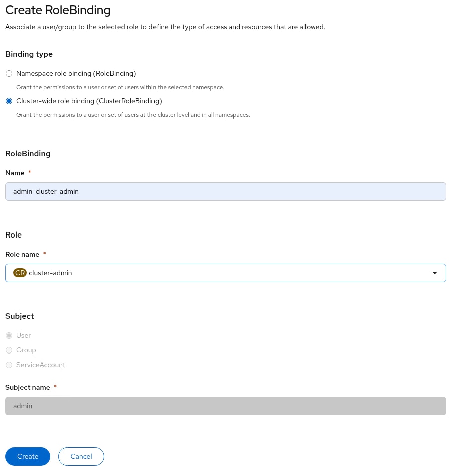
Step 8. Select User Management > Users, then select the admin user. Select the RoleBindings tab. Click the ellipses to the right of the user-settings RoleBinding to delete that RoleBinding, leaving only the cluster-admin RoleBinding.
Step 9. You can now log out of the cluster and log back in with httpasswd and the admin user. You now have full cluster-admin access to the cluster.
Deploy OpenShift Internal Image Registry
Procedure 1. Deploy OpenShift Image Registry
The OpenShift internal Image Registry can be used to locally store container images or customized container images and reduce container image downloads. If installing OpenShift Virtualization and the Migration Toolkit for Virtualization it will be used later to store the VMware VDDK container that accelerates converting and migrating VMware VMs to OpenShift Virtualization VMs.
Step 1. The image registry was removed during the OpenShift on Bare Metal installation. Change the Image Registry Operator configuration’s managementState from Removed to Managed:
oc patch configs.imageregistry.operator.openshift.io cluster --type merge --patch '{"spec":{"managementState":"Managed"}}'
Step 2. Modify the registry configuration:
oc edit configs.imageregistry.operator.openshift.io
Step 3. Change the storage field to the format shown below (leaving the claim field blank) to automatically create a 100GB image-registry-storage PVC in the openshift-image-registry namespace and save the config with “:x” (vim save and exit). This PVC will use the default storage class (ontap-nfs in this validation) and ideally should be a ReadWriteMany storage class, allowing multiple replicas of the registry to be deployed (only one replica is configured here):
storage:
pvc:
claim:
Step 4. Wait for the registry to become available:
oc get clusteroperator image-registry
NAME VERSION AVAILABLE PROGRESSING DEGRADED SINCE MESSAGE
image-registry 4.20.33 True False False 3s
Step 5. Ensure that your registry is set to managed to enable building and pushing of images:
oc describe configs.imageregistry/cluster | grep "Management State"
Management State: Managed
Management State: Managed
Management State: Managed
Step 6. To expose the registry using DefaultRoute:
oc patch configs.imageregistry.operator.openshift.io/cluster --patch '{"spec":{"defaultRoute":true}}' --type=merge
Step 7. To add a container to this internal registry, use either “podman pull” or a Dockerfile and use Deploy a Sample Containerized Application as a reference.
etcd is the key-value store for OpenShift, which persists the state of all resource objects.
For more information, see: https://docs.redhat.com/en/documentation/openshift_container_platform/4.20/html/backup_and_restore/control-plane-backup-and-restore.
Procedure 1. Back up etcd using a script
Assuming that the OCP-Installer VM is backed up regularly, regular OpenShift etcd backups can be taken and stored on the OCP-Installer VM.
Step 1. Create a directory on the OCP-Installer VM and create a directory inside this directory to store the backups:
cd
cd ocp
mkdir etcd-backup
cd etcd-backup
mkdir etcd-backups
ssh core@<control-0 ip>
exit
Note: For more robust storage of etcd backups, an NFS volume can be created on the NetApp storage and mounted as etcd-backups in the example above.
Step 2. The following script can be created and made executable to create and save the etcd backup:
cat etcd-backup-script
#! /usr/bin/bash
ssh core@<control-0 ip> sudo /usr/local/bin/cluster-backup.sh /home/core/assets/backup
ssh core@<control-0 ip> sudo chmod 644 /home/core/assets/backup/*
scp core@<control-0 ip>:/home/core/assets/backup/* /home/admin/ocp/etcd-backup/etcd-backups/
ssh core@<control-0 ip> sudo rm /home/core/assets/backup/*
chmod 600 /home/admin/ocp/etcd-backup/etcd-backups/*
find /home/admin/ocp/etcd-backup/etcd-backups -type f -mtime +30 -delete
Note: This script deletes backups over 30 days old.
Step 3. Using sudo, add execution of this script to /etc/crontab:
cat /etc/crontab
SHELL=/bin/bash
PATH=/sbin:/bin:/usr/sbin:/usr/bin
MAILTO=root
# For details see man 4 crontabs
# Example of job definition:
# .---------------- minute (0 - 59)
# | .------------- hour (0 - 23)
# | | .---------- day of month (1 - 31)
# | | | .------- month (1 - 12) OR jan,feb,mar,apr ...
# | | | | .---- day of week (0 - 6) (Sunday=0 or 7) OR sun,mon,tue,wed,thu,fri,sat
# | | | | |
# * * * * * user-name command to be executed
0 2 * * * admin /home/admin/ocp/etcd-backup/etcd-backup-script
Note: This example backs up etcd data daily at 2:00 am.
Step 4. In the event that an etcd restore is needed, the appropriate backup files would need to be copied back to a working control-plane node from the control-plane node:
ssh core@<control0 ip> sudo scp admin@<ocp installer vm IP>:/home/admin/ocp/etcd-backup/etcd-backups/snapshot_2026-06-12_172134.db /home/core/assets/backup/
ssh core@<control0 ip> sudo scp admin@<ocp installer vm IP>:/home/admin/ocp/etcd-backup/ static_kuberesources_2026-06-12_172134.tar.gz /home/core/assets/backup/
Step 5. To recover the cluster, see https://docs.redhat.com/en/documentation/openshift_container_platform/4.20/html-single/backup_and_restore/index#dr-restoring-cluster-state.
Add a Worker Node to an OpenShift Cluster
It is often necessary to scale up an OpenShift cluster by adding worker nodes to the cluster. This set of procedures describes the steps to add a node to the cluster. These procedures require a Cisco UCS Server connected to a set of Fabric Interconnects with all VLANs in the Server Profile configured. This procedure covers adding a FI-attached server to the cluster.
Procedure 1. Deploy a Cisco UCS Server Profile
Step 1. From the Configure > Templates page, to the right of the OCP-Worker template setup above, click the … and select Derive Profiles.
Step 2. Under the Server Assignment, select Assign Now and select the Cisco UCS server that will be added to the cluster as a Worker Node. Click Next.
Step 3. Assign the Server Profile an appropriate Name (for example, aa02-ocp-worker-0) and select the appropriate Organization. Click Next.
Step 4. Click Derive.
Step 5. From the Infrastructure Service > Profiles page, to the right of the just-created profile, click the … and select Deploy. Select Reboot Immediately to Activate and click Deploy.
Step 6. Wait until the profile deploys and activates.
Step 7. Click the server profile and go to Configuration > Identifiers and Inventory tabs note the server’s management IP, serial number, and the MAC address of network interface eno5.
Procedure 2. Create the Bare Metal Host (BMH)
Step 1. On the OCP-Installer VM, create the following yaml file (the example shown is for worker node worker-0:
cat worker-0-bmh.yaml
---
apiVersion: v1
kind: Secret
metadata:
name: worker-0-bmc-secret
namespace: openshift-machine-api
type: Opaque
data:
username: flexadmin
password: <password>
---
apiVersion: metal3.io/v1alpha1
kind: BareMetalHost
metadata:
name: worker-0
namespace: openshift-machine-api
spec:
bmc:
address: redfish-virtualmedia://10.102.2.237/redfish/v1/Systems/WZP29129G5N
credentialsName: worker-0-bmc-secret
disableCertificateVerification: True
bootMACAddress: 00:25:b5:a2:0a:5f
online: True
Note: Also note the bmc address. In this case redfish-virtualmedia is used to connect to the server. The URL has the server serial number at the end of the URL.
Step 2. Create the Bare Metal Host by typing the following:
oc project openshift-machine-api
oc create -f worker-0-bmh.yaml
Step 3. Verify that the BMH is created by selecting Compute > Bare Metal Hosts in the OpenShift Console. Over the next 20-30 minutes, the server will be inspected by booting the machine into an inspection environment and hardware details will be added to the Bare Metal Host. Wait until the host has a Status of Available.


Step 4. Click the BMH link and select the YAML tab. Just under the bmc: section, add the three lines shown below, starting with the customDeploy: line, and click Save.

Step 5. The worker BMH should now have a status of Externally provisioned.
Step 6. In the OpenShift Console, select Compute > MachineSets. Click the … to the right of the worker MachineSet and choose Edit Machine count. Use the plus sign to increase the count by one. Click Save.
Step 7. Click Compute > Machines. A new machine in the Provisioning phase should now appear in the list.

Procedure 3. Install Red Hat CoreOS on the New Worker
Step 1. Connect to the Red Hat Hybrid Cloud Console here: https://console.redhat.com/openshift/overview and log in with your Red Hat credentials. On the left, select Fleet management > Clusters. Under Clusters, click your cluster to open it.
Step 2. Select the Add Hosts tab. Click Add hosts.
Step 3. Do not change the field settings and click Next.
Step 4. For Provisioning type, leave Minimal image file selected. Browse to and select the SSH public key file used in the original cluster installation. Click Generate Discovery ISO.
Step 5. If your Cisco UCS Servers have the Intersight Advantage license installed, follow the procedure above to use the Cisco Intersight workflow to boot the server with the Discovery ISO. Then skip to Step 14.
Step 6. Click Download Discovery ISO. The file will download to your machine. Click Close.
Note: This is a slightly different ISO than the one used to install the cluster and must be downloaded to successfully add a node.
Step 7. Place the downloaded Discovery ISO on your HTTP or HTTPS web server and use a web browser to obtain the URL of the ISO.
Step 8. In Cisco Intersight, edit the Virtual Media Policy that is part of the server profile. On the Policy Details page, select Add Virtual Media.
Step 9. In the Add Virtual Media dialogue, leave CDD selected and select HTTP/HTTPS. Provide a name for the mount and add the URL for File Location.
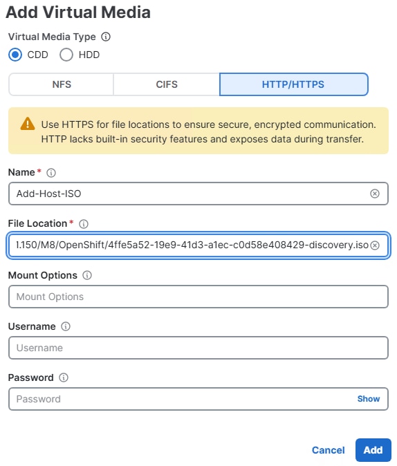
Step 10. Click Add.
Step 11. Click Save two times.
Step 12. Under Infrastructure Service > Profiles, click the three dots to the right of the newly added worker server profile and select Deploy. Select only the bottom checkbox and select Deploy.
Note: It is not necessary to deploy the remaining server profiles. The Inconsistent status will be resolved after CoreOS is installed on the newly added worker.
Step 13. When the deployment is complete, click the … to the right of the newly added worker profile and select Server Actions > Power > Power Cycle. In the popup, click Power Cycle. The reboot from the Discovery ISO can be monitored with a vKVM Console (Server Actions > Launch vKVM).
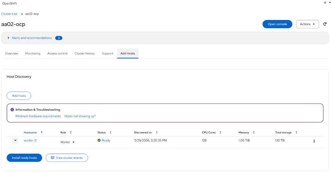
Step 15. Click the arrow to the left of the hostname to expand the host details. Use the Role drop-down list to select the appropriate Installation disk.
Step 16. Click Install ready hosts. The installation of CoreOS will take several minutes.
Note: Once the CoreOS installation completes (Status of Installed), the server will reboot, boot CoreOS, and reboot a second time.
Step 17. In Cisco Intersight, edit the vMedia policy and remove the virtual media mount. Go to Profiles > Server Profiles page, deploy the profile to the newly added worker profile without rebooting the host. The Inconsistent state on the remaining profiles should be cleared.
Step 18. In the OpenShift Console, select Compute > Nodes. Once the server reboots have completed, the newly added worker will appear in the list as Discovered. Click Discovered and then select Approve. Click Not Ready and select Approve.
Step 19. To link the Bare Metal Host to the Machine, select Compute > Machines. For the newly-added machine in the Provisioning Phase, note the entire machine name (for example, aa02-ocp-pvnh8-worker-0-8dmsb).

Step 20. Select Compute > Bare Metal Hosts. Select the BMH above the newly added BMH (for example, control-2). Select the YAML tab. Select and copy the entire consumerRef field right underneath the externallyProvisioned field.
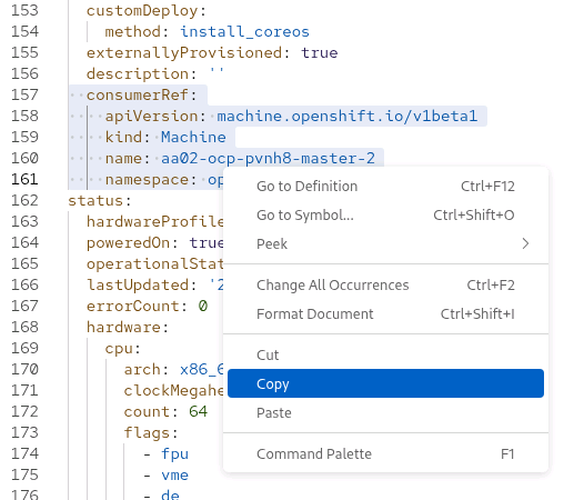
Step 21. Select Compute > Bare Metal Hosts. Select the BMH for the newly added BMH (for example, worker-0). Select the YAML tab. Place the cursor at the end of the externallyProvisioned: true line and press Enter to insert a new line. Backspace to the beginning of the line and then paste in the consumerRef field from the previous step. Replace the name field with the name noted above (for example, aa02-ocp-q9fz2-worker-0-hgbtz).
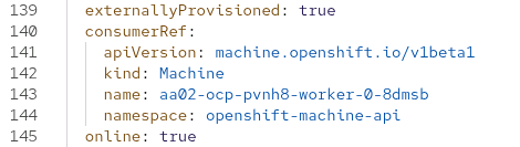
Step 22. Click Save. Click Compute > Machines. The newly added machine should now be in the Provisioned as node Phase.

Step 23. Select Compute > Bare Metal Hosts. The newly-added BMH should now be linked to a node.

Step 24. If configuring NVMe-TCP in this environment, change the new host’s NQN:
ssh core@worker-0
cat /etc/nvme/hostnqn
sudo nvme gen-hostnqn | sudo tee /etc/nvme/hostnqn
cat /etc/nvme/hostnqn
chronyc sources
timedatectl
ifconfig -a | more
sudo reboot # If NVMe-TCP interfaces do not have IPs, otherwise type exit.
Deploy a Sample Containerized Application
To demonstrate the installation of Red Hat OpenShift on Bare Metal on FlexPod Datacenter, a sample containerized application can be installed and run. In this case Stable Diffusion 3.5 large will be run utilizing an NVIDIA GPU. This installation will use NetApp DataOps Toolkit, installed above, to install a Jupyter Notebook and then python to run Stable Diffusion 3.5.
Procedure 1. Deploy Jupyter Notebook
Before deploying a Jupyter Notebook, first create a customized container on the OpenShift Installer VM in an sd-35 directory for Stable Diffusion 3.5 and place in the internal image registry.
Step 1. Create a Dockerfile:
cat > Dockerfile <<EOF
FROM nvcr.io/nvidia/pytorch:26.07-py3
RUN pip install --no-cache-dir --upgrade huggingface_hub
RUN pip install --no-cache-dir --upgrade diffusers transformers accelerate
RUN mkdir /workspace/.cache
RUN ln -s /workspace/.cache /root/.cache
EOF
Note: This container and other containers will be stored in your home directory on the Installer VM. Be sure to have at least 100GB available in this home directory to store these containers.
Step 2. Get the exposed registry URL:
HOST=$(oc get route default-route -n openshift-image-registry --template='{{ .spec.host }}')
echo $HOST
default-route-openshift-image-registry.apps.aa02-ocp.flexpodb4.cisco.com
Step 3. Log into the registry with podman after logging into the cluster with a cluster-admin user:
oc login -u admin -p <password>
podman login -u admin -p $(oc whoami -t) --tls-verify=false $HOST
Step 4. Build and tag the Stable Diffusion 3.5 image:
podman build . -t $HOST/openshift/sd-35:1.0
Successfully tagged default-route-openshift-image-registry.apps.aa02-ocp.flexpodb4.cisco.com/openshift/sd-35:1.0
468d8e8572603a9fe876bfb19389ac73757878f6269a73dda770b8dc23a7d272
Step 5. Push the image to the internal registry:
podman push $HOST/openshift/sd-35:1.0 --tls-verify=false
Step 6. Restore the default oc login:
cp <path>/kubeconfig ~/.kube/config
Step 7. From the OCP-Installer VM, run the following command to deploy a jupyter notebook with an nfs persistent storage 90G disk, one gpu, and the latest PyTorch container at this time:
netapp_dataops_k8s_cli.py create jupyterlab --workspace-name=sd-35-large -c ontap-nfs --size=90Gi --nvidia-gpu=1 -i image-registry.openshift-image-registry.svc:5000/openshift/sd-35:1.0
Step 8. Enter and verify a password for the notebook. The notebook is created in the ‘default’ namespace. The deployment will take a few minutes to reach Ready state:
Setting workspace password (this password will be required in order to access the workspace)...
Enter password:
Verify password:
Creating persistent volume for workspace...
Creating PersistentVolumeClaim (PVC) 'ntap-dsutil-jupyterlab-sd-35-large' in namespace 'default'.
PersistentVolumeClaim (PVC) 'ntap-dsutil-jupyterlab-sd-35-large' created. Waiting for Kubernetes to bind volume to PVC.
Volume successfully created and bound to PersistentVolumeClaim (PVC) 'ntap-dsutil-jupyterlab-sd-35-large' in namespace 'default'.
Creating Service 'ntap-dsutil-jupyterlab-sd-35-large' in namespace 'default'.
Service successfully created.
Creating Deployment 'ntap-dsutil-jupyterlab-sd-35-large' in namespace 'default'.
Deployment 'ntap-dsutil-jupyterlab-sd-35-large' created.
Waiting for Deployment 'ntap-dsutil-jupyterlab-sd-35-large' to reach Ready state.
Deployment successfully created.
Workspace successfully created.
To access workspace, navigate to https://10.102.2.200:32390
Step 9. Once the Workspace is successfully created, use a Web browser on a machine with access to the Baremetal subnet to connect to the provided URL. Log in with the password provided.
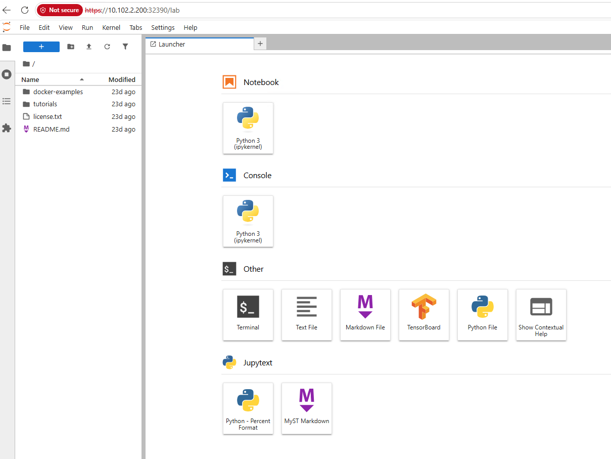
Step 10. Click the Terminal icon to launch a terminal in the PyTorch container. Connect to and login to https://huggingface.co/settings/tokens. Generate a token or re-use an existing token and copy the token to the clipboard. Connect the container to Hugging Face:
hf auth login --token <token>
Step 11. Click the + icon to add a window and select Python File. Add the following:
import torch
from diffusers import StableDiffusion3Pipeline
pipe = StableDiffusion3Pipeline.from_pretrained("stabilityai/stable-diffusion-3.5-large", torch_dtype=torch.bfloat16)
pipe = pipe.to("cuda")
image = pipe(
"Astronaut in a jungle, cold color palette, muted colors, detailed, 8k resolution",
num_inference_steps=28,
guidance_scale=3.5,
).images[0]
image.save("astronaut.png")
Step 12. Right-click untitled.py and select Rename Python File. Name the file Run-SD3.5.py and choose Rename. Click the x to the right of Run-SD3.5.py to close the file and click Save.
Step 13. In the Terminal window, run Stable Diffusion 3.5 Large by typing python Run-SD3.5.py. On the first run, the Stable Diffusion 3.5 Large model will be downloaded to persistent storage. Subsequent runs will take less time.
Step 14. Once the run is complete, double-click the astronaut.png file from the list on the left.
Step 15. You can run the “nvidia-smi” command from the Terminal window to see the GPU details.
Step 16. From the OpenShift console, on the left click Workloads > Pods. In the center pane, from the drop-down list select the default Project.

Step 17. On the left, select Deployments. In the center pane, select the Jupyterlab Deployment and then select the YAML tab. This info can be used as a guide to create a yaml file to do a command line deployment using oc of a pod. The YAML can also be modified to customize the deployment. If you edit the deployment, you will need to delete the corresponding pod to respin the container and you will then need to add the symbolic link.
Deploy OpenShift Virtualization
Procedure 1. Deploy the OpenShift Virtualization Operator
Step 1. In the OpenShift console, select Ecosystem > Software Catalog. In the search box, type Virtualization. Select OpenShift Virtualization provided by Red Hat.
Step 2. Click Install. Click Install again to deploy OpenShift Virtualization in the openshift-cnv namespace.
Step 3. Once the operator is installed, click Create Hyperconverged. Scroll down and click Create.
Step 4. Log back into the web console as required and wait for the kubevirt-hyperconverged status to become Conditions: ReconcileComplete, Available, Upgradeable.
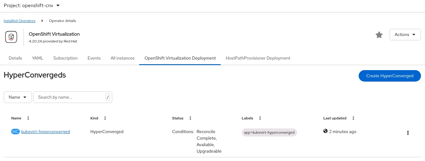
Step 5. Connect and log into the RHEL Activation Keys page in the Red Hat Hybrid Cloud Console at https://console.redhat.com/insights/connector/activation-keys#SIDs=&tags=. If an appropriate Activation Key is not present and if your user permissions allow, use Create activation key to create a RHEL Activation Key for OpenShift Virtualization automatic subscription activation for RHEL VMs. Note the Key Name and Organization ID.
Step 6. In the OpenShift Console, select Virtualization > Overview > Settings. Expand Guest management and then expand Automatic subscription of new RHEL VirtualMachines. Under Subscription type, select Monitor and manage subscriptions. Fill in the Activation key and Organization ID and click Apply. Optionally, turn on Enable auto updates for RHEL VirtualMachines to enable automatic updates on all RHEL VMs and ensure Enable guest system log access is enabled to enable access to the VM guest system logs.
Procedure 2. Configure VM Network Connectivity
In this lab validation, virtual machines are connected to the network with NMState NodeNetworkConfigurationPolicy (NNCP) bridges and NetworkAttachmentDefinitions (NAD). A bridge interface can be created on a network interface (bond or NIC) that supports multiple allowed VLANs. The VM network bridge was created earlier. An NAD can then be created with a VLAN tag and the MTU can be specified. The VM NIC is then connected to the NAD. NADs created in the default namespace are available for VMs in any namespace. NADs can also be created in individual namespaces and are only available for VMs in that namespace.
Step 1. Complete the setup of the Live Migration network by creating the following yaml file in the NMState directory and create the network attachment definition:
cat live-migrate-nad.yaml
apiVersion: "k8s.cni.cncf.io/v1"
kind: NetworkAttachmentDefinition
metadata:
name: live-migration-network-bond0-3002
namespace: openshift-cnv
spec:
config: '{
"cniVersion": "0.3.1",
"name": "migration-bridge",
"type": "macvlan",
"master": "bond0.3002",
"mode": "bridge",
"ipam": {
"type": "whereabouts",
"range": "192.168.2.0/24"
}
}'
oc create -f live-migrate-nad.yaml
Step 2. In the OpenShift console, select Virtualization > Overview > Settings > General settings > Live Migration. For the Live migration network, select live-migration-network-bond0-3002.
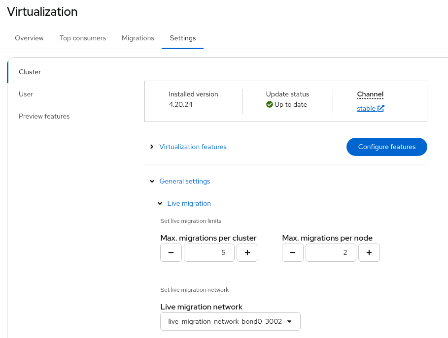
Step 3. Select Networking > NetworkAttachmentDefinitions. At the top of the page, select the default Project. On the right, click Create Network Attachment Definition. In our example, we are creating a VM network attachment on VLAN 1024. The Name is vm-network-vlan-1024. For Network Type, select Linux bridge. For Bridge name, enter br-vm-network. For VLAN tag number, enter 1024. Uncheck the MAC spoof check checkbox. Click Create.
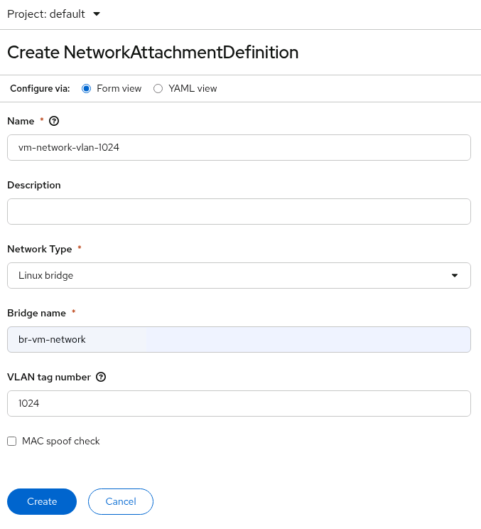
Step 4. If it is desired to provide VM in-guest access to the ocp-nfs VLAN and subnet, create a Network Attachment Definition for NFS. For this definition, do not specify a VLAN since the NFS VLAN is the native VLAN for the br-vm-network bridge that is on bond0 as shown in the first screenshot below. For the NFS NAD, select the NAD and in the Network Attachment Definition details, select the YAML tab. In the YAML tab, on the next to last config line, add mtu: 9000, as shown in the second screenshot below. Click Save.
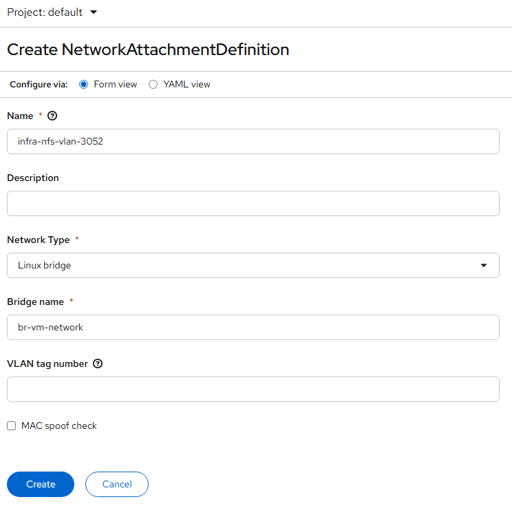
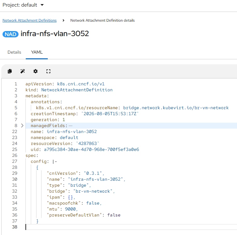
Step 5. Add any additional needed VM Network Attachment Definitions.
Note: Network Attachment Definitions created in the default project or namespace are available for VMs created in any project or namespace. Network Attachment Definitions created in a project namespace other than default are only available to VMs in that project or namespace.
Procedure 3. Add Framework for vTPM
Microsoft Windows 11 has a requirement for a Trusted Platform Module (TPM) in the machine. With Red Hat OpenShift Virtualization, a virtual TPM (vTPM) can be added to a VM. A virtual Trusted Platform Module (vTPM) device functions like a physical Trusted Platform Module (TPM) hardware chip. You can use a vTPM device with any operating system, but Windows 11 requires the presence of a TPM chip to install or boot. A vTPM device allows VMs created from a Windows 11 image to function without a physical TPM chip. If you do not enable vTPM, then the VM does not recognize a TPM device, even if the node has one.
A vTPM device also protects virtual machines by storing secrets without physical hardware. OpenShift Virtualization supports persisting vTPM device state by using Persistent Volume Claims (PVCs) for VMs. You must specify the storage class to be used by the PVC by setting the vmStateStorageClass attribute in the HyperConverged custom resource (CR). The storage class must be of type Filesystem and support the ReadWriteMany (RWX) access mode. Currently, with NetApp Trident, only the NFS storage class supports these parameters.
Step 1. On the OpenShift Installer VM, edit the HyperConverged custom resource:
oc edit hyperconverged kubevirt-hyperconverged -n openshift-cnv
Step 2. Scroll down to the spec: section and add the following with the nfs storage class name:
spec:
vmStateStorageClass: <storage_class_name>
Step 3. Save the HyperConverged custom resource with x: (vim save).
Step 4. Later, a vTPM can be added to a VM by editing the VM with:
oc edit vm <vm_name> -n <namespace>
Step 5. Under devices: add the vTPM with:
devices:
tpm:
persistent: true
Step 6. Save the updated VM specification with x:. To remove the vTPM, set persistent: to false.
Procedure 4. Configure OpenShift Virtualization High Availability (HA)
In this procedure, Operators will be configured to provide node monitoring to allow virtual machines (VMs) to be quickly evacuated from failing nodes.
Step 1. In the OpenShift console, select Ecosystem > Software Catalog. In the Filter box, type SNR. Click the Self Node Remediation Operator Provided by Red Hat. Click Install. Click Install again. When the Operator is installed, click View Operator.
Step 2. In the OpenShift console, select Ecosystem > Software Catalog. In the Filter box, type NHC. Click the Node Health Check Operator Provided by Red Hat. Click Install. Click Install again. When the Operator is installed, click View Operator.
Step 3. Select the Node Health Check tab. Click Create NodeHealthCheck. Give the NodeHealthCheck a name such as control-plane-worker-nhc. Under Selector > Selector labels, use the pulldown to select Role Worker. Since we have combination control plane / worker nodes, this selection selects all our nodes. Click Create.
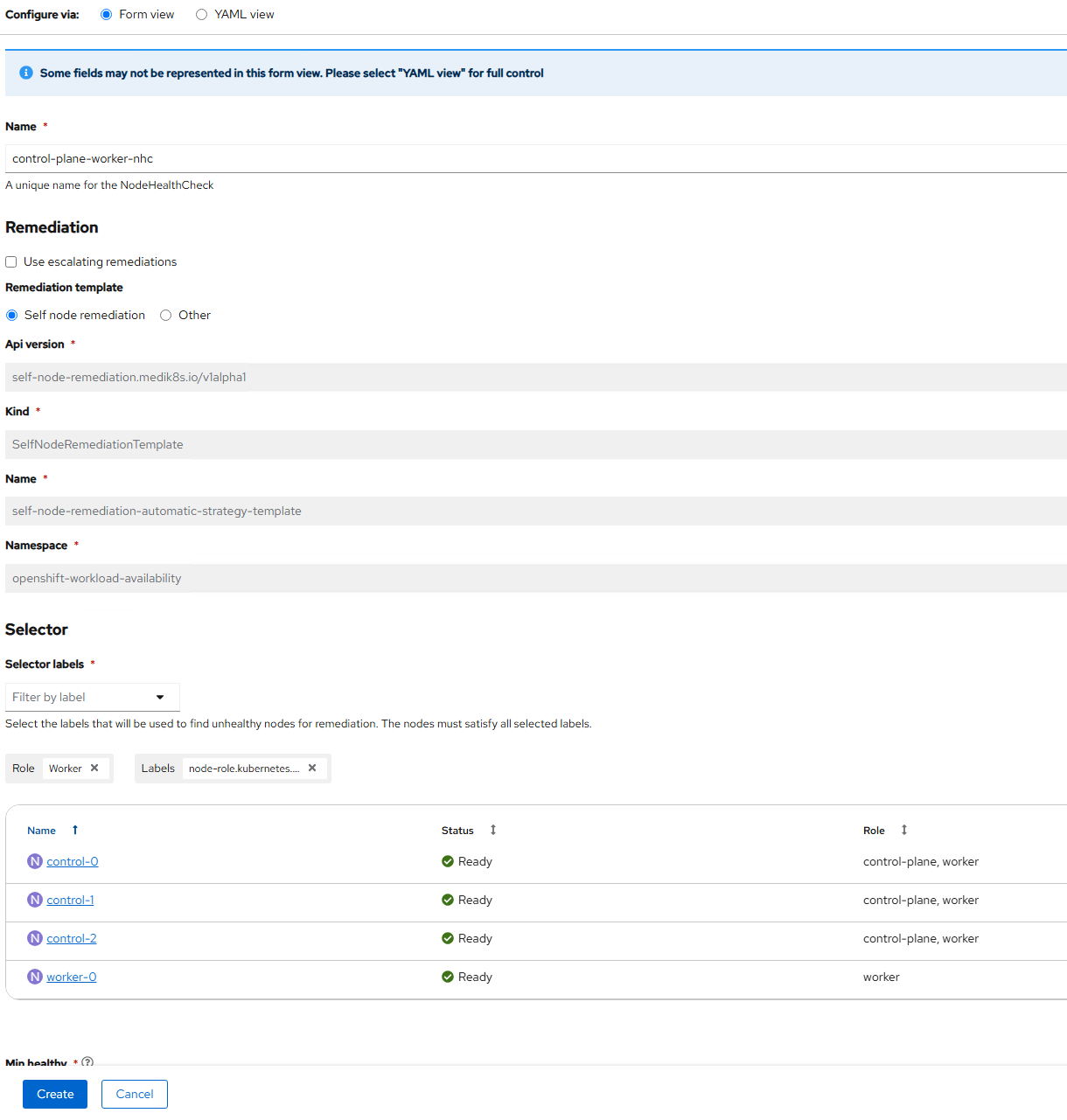
Step 4. If necessary, create a second NodeHealthCheck to ensure all nodes (control plane) are covered.
Step 5. In the OpenShift console, select Ecosystem > Software Catalog. In the Filter box, type FAR. Click the Fence Agents Remediation Operator Provided by Red Hat. Click Install. Click Install again. When the Operator is installed, click View Operator.
Step 6. Create and apply the following YAML files to configure FAR and to connect to NHC:
cat far-redfish-secrets.yaml
apiVersion: v1
kind: Secret
metadata:
name: far-redfish-control-0
namespace: openshift-workload-availability
type: Opaque
stringData:
--username: flexadmin
--password: <password>
---
apiVersion: v1
kind: Secret
metadata:
name: far-redfish-control-1
namespace: openshift-workload-availability
type: Opaque
stringData:
--username: flexadmin
--password: <password>
---
apiVersion: v1
kind: Secret
metadata:
name: far-redfish-control-2
namespace: openshift-workload-availability
type: Opaque
stringData:
--username: flexadmin
--password: <password>
---
apiVersion: v1
kind: Secret
metadata:
name: far-redfish-worker-0
namespace: openshift-workload-availability
type: Opaque
stringData:
--username: flexadmin
--password: <password>
cat far-remediation-template.yaml
apiVersion: fence-agents-remediation.medik8s.io/v1alpha1
kind: FenceAgentsRemediationTemplate
metadata:
name: far-redfish-workers
namespace: openshift-workload-availability
spec:
template:
spec:
agent: fence_redfish
nodeparameters:
--ip:
control-0: "<BMC IP>"
control-1: "<BMC IP>"
control-2: "<BMC IP>"
worker-0: "<BMC IP>"
--systems-uri:
control-0: "/redfish/v1/Systems/<Server Serial>"
control-1: "/redfish/v1/Systems/<Server Serial>"
control-2: "/redfish/v1/Systems/<Server Serial>"
worker-0: "/redfish/v1/Systems/<Server Serial>"
nodeSecretNames:
control-0: far-redfish-control-0
control-1: far-redfish-control-1
control-2: far-redfish-control-2
worker-0: far-redfish-worker-0
sharedparameters:
--action: "reboot"
--ipport: "443"
# Remove this when the BMC certificate is trusted.
--ssl-insecure: ""
remediationStrategy: OutOfServiceTaint
retrycount: 5
retryinterval: "10s"
timeout: "120s"
cat far-to-nhc.yaml
apiVersion: remediation.medik8s.io/v1alpha1
kind: NodeHealthCheck
metadata:
name: far-redfish-workers
spec:
minHealthy: "51%"
stormCooldownDuration: "60s"
selector:
matchExpressions:
- key: node-role.kubernetes.io/worker
operator: Exists
remediationTemplate:
apiVersion: fence-agents-remediation.medik8s.io/v1alpha1
kind: FenceAgentsRemediationTemplate
name: far-redfish-workers
namespace: openshift-workload-availability
unhealthyConditions:
- type: Ready
status: "False"
duration: "300s"
- type: Ready
status: "Unknown"
duration: "300s"
oc project openshift-workload-availability
oc create -f far-redfish-secrets.yaml
oc create -f far-remediation-template.yaml
oc create -f far-to-nhc.yaml
Step 7. Verify the far configuration at Ecosystem > Installed Operators > Node Health Check Operator > Node Health Check.
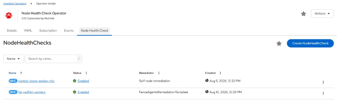
Procedure 5. Configure OpenShift Virtualization Load Balancing
The Load Aware Descheduler balances VM distribution across the cluster Nodes based on CPU utilization and Node CPU pressure.
Step 1. In the OpenShift console, select Ecosystem > Software Catalog. In the Filter box, type descheduler. Click the Kube Descheduler Operator Provided by Red Hat. Click Install. Click Install again. When the Operator is installed, click View Operator.
Step 2. Select the Kube Descheduler tab. Click Create KubeDescheduler. Select Form view.
Step 3. Use the mode pulldown to select Automatic. Expand profiles and using the Value pulldown, select KubeVirtRelieveAndMigrate. Click Create. Wait for the KubeDescheduler Status to clear (“-“).
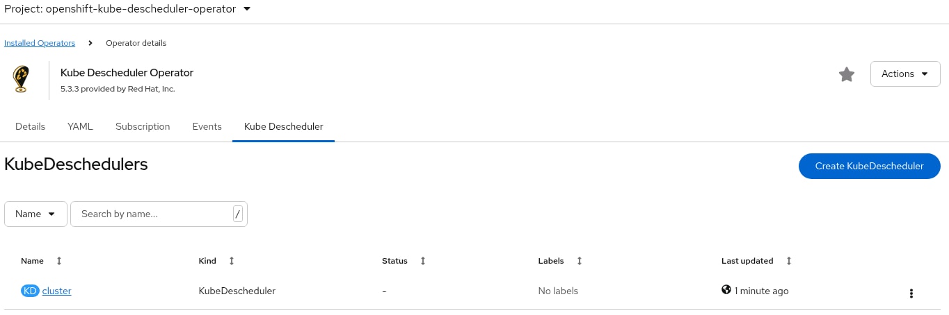
Procedure 6. Create a RHEL VM
For Red Hat Enterprise Linux (RHEL) 8 and 9, Fedora, and CentOS Stream 9 VMs, a VM disk image is already loaded by default. In the OpenShift Console, check Virtualization > Overview > Settings > General settings > Automatic images download to verify that these images are downloaded automatically. Red Hat recommends not installing VMs in the openshift-cnv namespace. VMs can be created in the default namespace or in any other namespace. Namespaces can be used to group and separate VMs, and specific Network Attachment Definitions can be created within a namespace and only used by VMs within that namespace.
Note: The default VM images are stored as Volume Snapshots in the openshift-virtualization-os-images namespace or project. A Volume Snapshot Class must be defined for these images to be downloaded.
Note: The default VM images are downloaded using the current default storage class. This same storage class must be used when building VMs from these images. A VM image with one storage class cannot be used to build a VM disk in a different storage class.
Step 1. In the OpenShift Console, select Virtualization > VirtualMachines. Uncheck Show only projects with VirtualMachines. Select Project: default or use any other custom project or namespace where you want to place the VM. If using a custom project or namespace, create any specific Network Attachment Definitions within that namespace, remembering that the VLANs used in those Network Attachment Definitions need to be configured in the Cisco Nexus switches, in the Cisco UCS Fabric Interconnects VLAN policy, and in the Cisco UCS vNIC Ethernet Network Group policy.
Step 2. Click the Create VirtualMachine drop-down list and select From template. Click Red Hat Enterprise Linux 9 VM.
Step 3. Do not select Boot from CD. Also, leave Disk source set to Template default. Adjust the Disk size as necessary. Adjust CPU|Memory as necessary. Click Optional Parameters and adjust, as necessary. Change the VirtualMachine name and click Customize VirtualMachine.
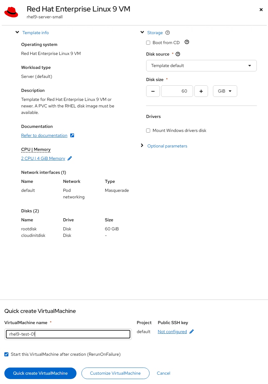
Step 4. On the Customize and create VirtualMachine page, select the Network Interfaces tab. Click the ellipses and select Edit. Change the Name of the network interface if desired and from the Network drop-down list, select an appropriate Network Attachment Definition. Click Save.
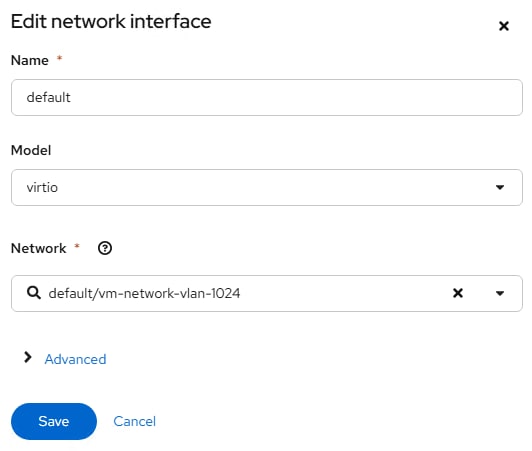
Step 5. Click the Disks tab and adjust, as necessary.
Step 6. Click the Scripts tab. Edit Cloud-init, select Script and adjust as necessary (for example, add ssh_pwauth: True right after the password line in the script to allow ssh password authentication login). Click Save and Apply.
Step 7. Once all tabs have been reviewed, click Create VirtualMachine.
Step 8. Once the VM has been Provisioned and Started, click the Console tab. You can click Guest login credentials to see the default user name and password. This user has sudo privileges. Login and configure the VM. If you configured the automatic subscription key insertion, you can use “sudo dnf” to add and upgrade packages.
Step 9. To clone the VM, go to Virtualization > VirtualMachines > VirtualMachine details, and from the Actions drop-down list, select Clone. Give the VM a new name, which will be configured as the new hostname by CloudInit and select the checkbox for Start VirtualMachine once created. Click Clone.
Procedure 7. Create a Windows VM Boot Source
For Windows VMs first time creation, a Windows Installation ISO and installation key are needed. Once the first VM for a given version of windows is created, the boot disk can be stored as a boot image to create more VMs in the future. In this example, Windows Server 2025 Standard will be installed and a user template created.
Step 1. In the OpenShift Console, select Virtualization > Templates. Select the openshift Project. Scroll down until you see windows2k25-server-large. Click the three dots to the right of windows2k25-server-large and select Clone.
Step 2. Give the template a descriptive name and select a project where you will store many VMs (for example, default). You can add your Company name for Template provider. Click Clone.
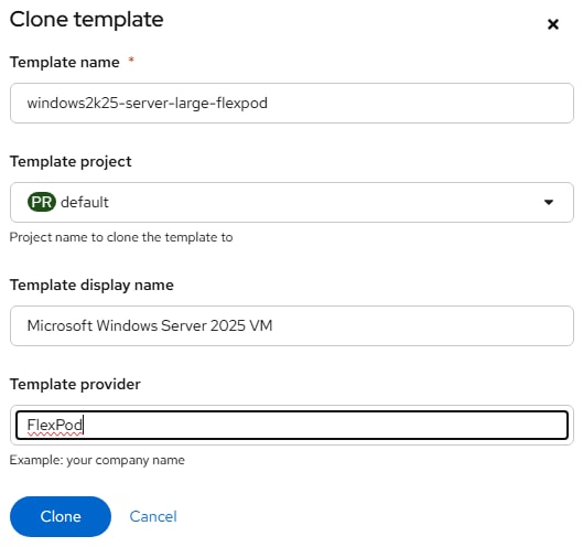
Step 3. The default Windows 11, Windows Server 2022, and Windows Server 2025 templates contain a vTPM by default. Windows 11 requires a vTPM for installation, but Windows Server 2022 and 2025 will install without a vTPM in the configuration. In Windows Server 2022 and 2025, a vTPM is only required if Bitlocker is deployed. You can optionally remove the vTPM and persistent EFI from the Template just created. Select the YAML tab. Scroll down to lines 192 and 193 and delete those lines. Then scroll down further to around line 216 and change persistent: true under efi: to persistent: false. Click Save and then click Reload.
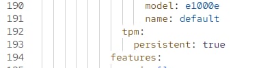

Step 4. Select the Network interfaces tab. Click the three dots to the right of the default interface and select Edit. Change the Model to virtio and optionally select a more appropriate setting for Network. Click Save.
Step 5. Select the Disks tab. Click the three dots to the right of the rootdisk and select Edit. Change the interface from SATA to VirtIO, leave the disk size set to 64 and click Save.
Step 6. In the OpenShift Console, select Virtualization > VirtualMachines. Select Project: default or use any other custom project or namespace where you want to place the VM. If using a custom project or namespace, create any specific Network Attachment Definitions within that namespace, remembering that the VLANs used in those Network Attachment Definitions need to be configured in the Cisco Nexus switches, in the Cisco UCS Fabric Interconnects VLAN policy, and in the vNIC Ethernet Network Group policy.
Step 7. From the Create drop-down list select From template. Under User templates, select the Microsoft Windows Server 2025 VM template.
Step 8. Select Boot from CD. For CD source, from the drop-down list select Upload (Upload a new file to a PVC). Click Browse and browse to and Open the Windows Server 2025 ISO. Adjust the CD Disk size as necessary to be a little larger than the ISO. Leave Disk source set to Blank and leave Disk size set to 64GiB. Make sure Mount Windows drivers disk is selected. Change the VirtualMachine name to something like win2k25-template and click Customize VirtualMachine.
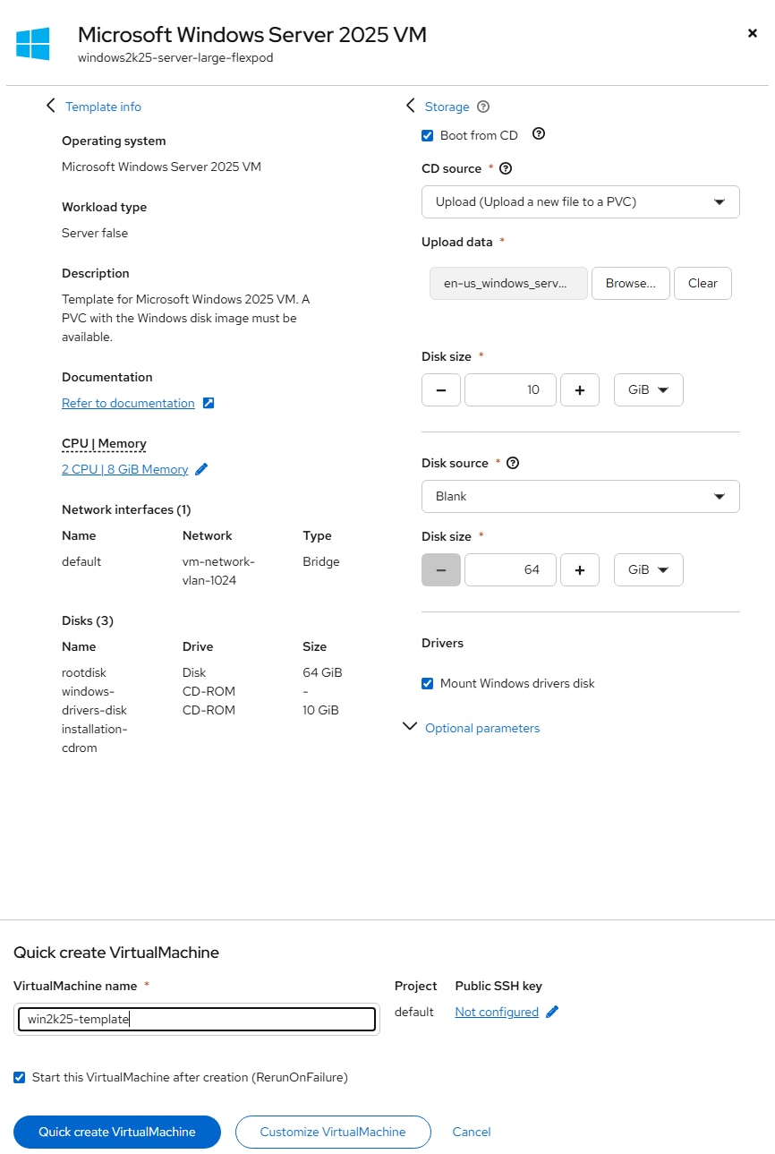
Step 9. If you get an Invalid certificate error, click the URL, click Advanced and then click Continue to cdi-uploadproxy…. When you get to the message “This page isn’t working,” close the tab. Click Customize VirtualMachine again. Wait a few minutes for the ISO to be uploaded to a PVC.
Step 10. On the Customize and create VirtualMachine page, select the Network Interfaces tab. If anything needs to be changed about the network interface, click the three dots to the right of the interface and select Edit.
Step 11. Click the Disks tab and using the three dots to the right of rootdisk, click Edit. If a Storage Class other than the default storage class is desired for the disk, select the new Storage Class. Click Save.
Note: For Windows, if virtio is used for rootdisk, it is critical that the windows-drivers-disk is mounted so that the virtio driver can be loaded during the installation process.
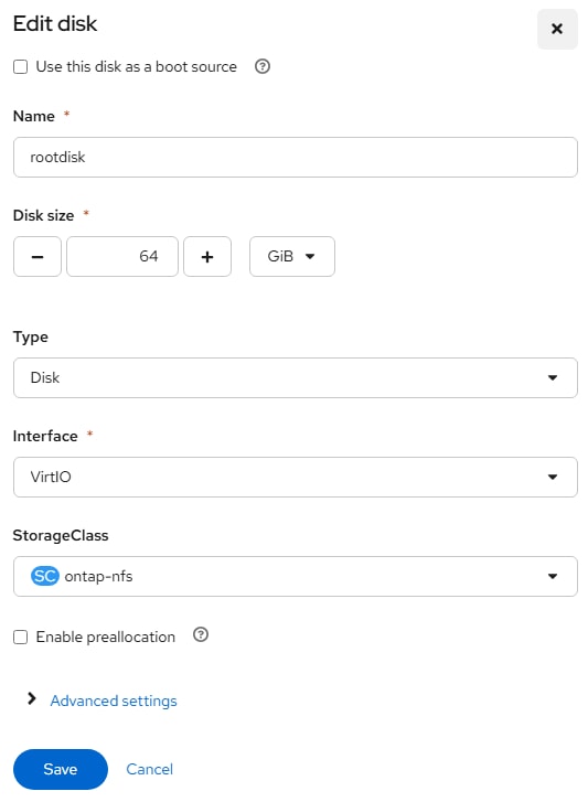
Step 12. Once all tabs have been reviewed, click Create VirtualMachine.
Step 13. Once the VM has been Provisioned and Started, click the Console tab. Click on the console window and hit a key when you see Press any key to boot from CD or DVD…
Step 14. Select the appropriate Language and Time and currency format and click Next.
Step 15. Select the appropriate keyboard and click Next.
Step 16. Select the I agree everything… checkbox and click Next.
Step 17. Enter a valid product key and click Next.
Step 18. Select Windows Server 2025 Standard (Desktop Experience) and click Next.
Step 19. Click Accept.
Step 20. Click Load driver. Click Browse. Expand the virtio-win CD Drive. Expand amd64 and select the 2k25 folder. Click OK. Select Red Hat VirtIO SCSI controller and click Install.
Step 21. If you get the error stating “Microsoft Server Operating System can’t be installed on this drive. (Show details),” click on the error link. Click OK to get the drive online.
Step 22. Select Drive 0 Unallocated Space and click Next.
Step 23. Click Install.
Step 24. The Windows installation will complete and do not hit a key to boot from CD or DVD when the VM reboots. The VM will reboot more than once.
Step 25. Enter and confirm an Administrator password and click Finish.
Step 26. From the Send key drop-down list, send Ctrl + Alt + Delete to the VM. Enter the Administrator password to login.
Step 27. Click Accept.
Step 28. Close Server Manager. Use the Folder icon in the Task Bar to open File Explorer. On the left, select This PC. Double-click CD Drive virtio-win. Scroll down and double-click virtio-win-guest-tools. Select the checkbox to agree to the license terms and conditions and click Install. Complete the installation. Reboot the VM.
Step 29. Log back into the VM and if necessary configure the network interface. Type update in the search box, select Check for updates, install all Windows updates, and restart the VM.
Step 30. Log back into the VM and make any other adjustments, such as setting the VM timezone and time or setting the VM hostname. Then, from the VirtualMachine details > Actions drop-down list to Stop the VM.
Step 31. Select the Configuration tab. On the left, select Storage. Uncheck Mount Windows drivers disk. Using the three dots to the right of the installation-cdrom, select Detach. Click Detach again. The rootdisk should now be the VM’s only disk and it should show bootable.
Step 32. From the Actions drop-down list, start the VM. Select the Console tab. Log into the VM.
Step 33. Optionally, use a command-line window and first “reagentc /disable” and then “diskpart” to delete the rootdisk Recovery Partition 4. Open Disk Management and extend the C: volume to the end of the disk.
Step 34. In the OpenShift console, select the Snapshots tab for the VM. Click Take snapshot. Name the snapshot (win2k25-template-snapshot-before-sysprep) and click Save. Wait for the snapshot to be Ready. Return to the Console tab for the VM.
Step 35. Open File Explorer and navigate to This PC > C:\Windows\System32\Sysprep. Double-click sysprep. Select Generalize. Change the Shutdown Options to Shutdown and click OK. The VM will shut down. If the VM begins to Start, from the Actions drop-down list select Stop.
Step 36. To create a Windows Server 2025 Standard Bootable volume, select Virtualization > Bootable volumes. Switch to the openshift-virtualization-os-images Project. Make sure windows2k25 is not listed. If windows2k25 is listed, delete it. Use the Add volume drop-down list to select With form. For Source type, select Use existing volume. For Volume project, select default or the project where the Windows Server 2025 VM is located. For Volume name, select the PVC for the Windows Server 2025 VM rootdisk. Select the appropriate StorageClass. Do not change the disk size. For volume name, enter windows2k25. For Destination project, select openshift-virtualization-os-images. For Preference, select windows.2k25.virtio. For DefaultInstanceType, select Red Hat provided > U series > large: 2 CPUs, 8 GiB Memory or an appropriate DefaultInstanceType. For Architecture, select amd64. Click Save.
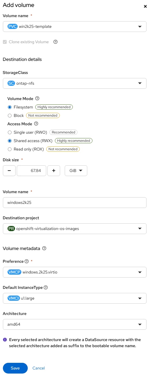
Step 37. The windows2k25-amd64 Data Source should now appear under Bootable volumes. Wait for the Clone in Progress to complete and the volume to reappear.
Step 38. Select Project: default. Select Virtualization > Templates. Select the windows2k25-server-large… template. Select the YAML tab and scroll down to around line 237. Change the value field under DATA_SOURCE_NAME from win2k25 to windows2k25-amd64. Click Save and Reload.
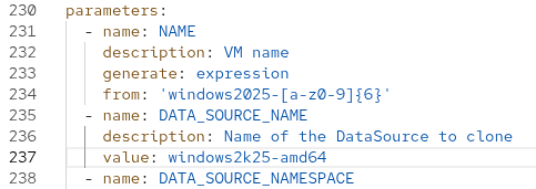
Step 39. Select Virtualization > Templates. The template now displays the Source available.
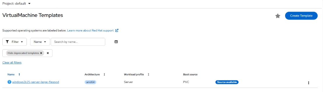
Step 40. Select the windows2k25-server-large-flexpod template and select the Disks tab. Click the three dots to the right of the rootdisk and select Edit. Increase the disk size by 5% by dividing the disk size by 0.95 and rounding up. In this example, a 64 GiB disk is increased to 68 GiB. Click Save.
Step 41. Return to Virtualization > VirtualMachines > win2k25-template. Select the Snapshots tab. Click the three dots to the right of the snapshot created earlier and select RestoreVirtualMachine from snapshot. Click Restore. Once the restore is completed, click the three dots to the right of the snapshot and select Delete snapshot. Click Delete snapshot. The VM can now be used to update the bootable volume following the process above.
Step 42. To create a VM from this Template, select Virtualization > VirtualMachines under Project: default. Use the Create drop-down to select From template. Under Template project, select User templates. Select the newly created template with Source available. When using this template, the Disk source can be left at Template default without checking Boot from CD. Also, make sure to click the Network tab and Disk tab to ensure these are set properly. Click Create VirtualMachine.
Step 43. When the new VM is brought up, Disk Management will need to be used to extend the C: volume to the end of the disk. The new VM will also need to be assigned a new VM host name.
Procedure 8. VM Tuning
For tuning OpenShift Virtualization VM network interfaces and disks, please see OpenShift Virtualization - Tuning & Scaling Guide - Red Hat Customer Portal. In the validation lab when using VM disk tuning with the supplemental pool of IO disk threads, the 100% read performance of NVMe-TCP disks more than doubled.
Procedure 9. Install the virtctl Command Line Utility
The virtctl client is a supplemental command-line utility for managing virtualization resources from the command line. For more information, see https://docs.redhat.com/en/documentation/openshift_container_platform/4.20/html/virtualization/getting-started#virt-using-the-cli-tools.
Step 1. Using Edge from the OpenShift Installer VM, in the OpenShift Console, select Virtualization > Overview. If necessary, close the Welcome to OpenShift Virtualization popup. In the upper right corner of the, click Download the virtctl command-line utility. On the Command Line Tools page, click Download virtctl for Linux for x86_64.
Step 2. From a terminal window on the OpenShift Installer VM, type the following commands:
cd ~/Downloads
tar -xzvf virtctl.tar.gz
sudo cp virtctl /usr/local/bin/
rm virtctl*
Step 3. Use virtctl to restart a VM. Go to Virtualization > VirtualMachines in the default project to Monitor from the OpenShift Console:
oc project default
oc get vms
NAME AGE STATUS READY
rhel9-test-01 26h Running True
rhel9-test-nfs 5h1m Running True
rhel9-test-nvme-tcp 5h Running True
win2k25-01 7h46m Running True
win2k25-template 9h Stopped False
virtctl restart rhel9-test-01
Procedure 10. VM Snapshots
Snapshots can be created at the VM level and at the VM disk level. With FlexPod, NetApp Trident applies these snapshots on the storage volumes where the VM disks are located. The VM can then be restored to the point in time that the snapshot was taken. Also, the default NetApp Trident backends and storage classes configured earlier in this document leave the Default snapshot policies on the VM disk volumes in storage. A VM could be shut down and NetApp tools used to restore a NetApp snapshot of the volume, restoring the disk to a point in time. For more information on VM snapshots, go to: https://docs.redhat.com/en/documentation/openshift_container_platform/4.20/html/virtualization/backup-and-restore#virt-backup-restore-snapshots.
Step 1. To create a VM snapshot in the OpenShift Console, select Virtualization > VirtualMachines. At the top, select the project where the VM is located and then select the VM.
Step 2. To take a VM snapshot, click Take snapshot. Give the snapshot a unique name and click Save.
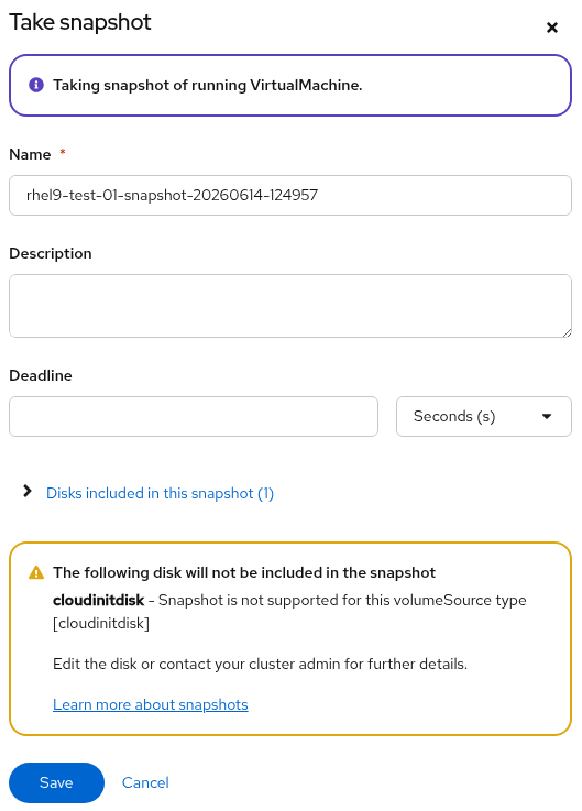
Step 3. Select the Snapshots tab. The new snapshot now appears in the list. Click the ellipses to the right of the snapshot for snapshot options. Notice that Restore VirtualMachine from snapshot is greyed out since the VM would need to be stopped to restore the snapshot.
Procedure 11. Deploy the Migration Toolkit for Virtualization Operator
The Migration Toolkit for Virtualization Operator is used to migrate VMs from VMware and other sources into OpenShift Virtualization and to migrate VMs between OpenShift clusters.
Step 1. In the OpenShift Console, select Ecosystem > Software Catalog. Type Migration in the search box and choose Migration Toolkit for Virtualization Operator provided by Red Hat. Click Install. Leave all settings at their defaults and click Install again.
Step 2. Once the Operator is installed, click Create ForkliftController. Click Create. Wait for the Status to become “Condition: Running.” Re-login to the OpenShift console.
Step 3. On the left, select Migration for Virtualization > Overview. The Migration Toolkit for Virtualization has been successfully installed.
Procedure 12. Add the VMware VDDK Container to the Image Registry
Step 1. On your OpenShift installer VM, create and navigate to a temporary directory:
mkdir ~/<cluster name>/vddk && cd ~/<cluster name>/vddk
Step 2. Using Edge, navigate to the Broadcom VMware VDDK download page. Select Login and log into the site. Select version 9.1.0.0 for Linux (or the version that matches your vCenter) and click Download.
Note: A Broadcom VMware login will be needed to download the VDDK. Also, it is assumed you are migrating from vSphere 8.0 Update 1 or later.
Step 3. Move the downloaded file to the temporary directory:
mv ~/Downloads/VMware-vix-disklib-9.1.0.0.25379531.x86_64.tar.gz ./
ls
VMware-vix-disklib-9.1.0.0.25379531.x86_64.tar.gz
Step 4. Extract the VDDK archive:
tar -xzvf VMware-vix-disklib-9.1.0.0.25379531.x86_64.tar.gz
Step 5. Create a Dockerfile:
cat > Dockerfile <<EOF
FROM registry.access.redhat.com/ubi8/ubi-minimal
USER 1001
COPY vmware-vix-disklib-distrib /vmware-vix-disklib-distrib
RUN mkdir -p /opt
ENTRYPOINT ["cp", "-r", "/vmware-vix-disklib-distrib", "/opt"]
EOF
Step 6. Get the exposed registry URL:
HOST=$(oc get route default-route -n openshift-image-registry --template='{{ .spec.host }}')
echo $HOST
default-route-openshift-image-registry.apps.aa02-ocp.flexpodb4.cisco.com
Step 7. Log into the registry with podman after logging into the cluster with a cluster-admin user:
oc login -u admin -p <password>
podman login -u admin -p $(oc whoami -t) --tls-verify=false $HOST
Step 8. Build and tag the VDDK image:
podman build . -t $HOST/openshift/vddk:9.1.0.0
Successfully tagged default-route-openshift-image-registry.apps.aa02-ocp.flexpodb4.cisco.com/openshift/vddk:9.1.0.0
dce2bb998a9f6d9685fa4805a88aaca897b29835c4bcfb727a5798ed994d65d1
Step 9. Push the image to the image registry:
podman push $HOST/openshift/vddk:9.1.0.0 --tls-verify=false
Getting image source signatures
Copying blob 12d5399f6d50 done |
Copying blob 325e71f5b538 done |
Copying blob 7e02eaad2ba1 done |
Copying config 120bbf6b2d done |
Writing manifest to image destination
Step 10. Restore the default oc login:
cp <path>/kubeconfig ~/.kube/config
Procedure 13. Add a VMware Migration Provider
Step 1. In the OpenShift Console, select Migration for Virtualization > Providers. Switch to the openshift-mtv project. Click Create Provider.
Step 2. For Provide type, select VMware vSphere. For Provider name, enter your vCenter hostname with all lowercase characters. Select the vCenter Endpoint type. For URL, enter https://<vcenter-fqdn>/sdk. For VDDK setup, select Manually specify the VDDK image URL. For the VDDK init image, enter image-registry.openshift-image-registry.svc:5000/openshift/vddk:9.1.0.0. For Provider credentials, use administrator@vsphere.local and the corresponding password. Select to Skip certificate validation. Click Create provider.
Procedure 14. Install the NetApp Shift Operator in OpenShift
Manually deploy the NetApp Shift toolkit as a containerized service with NetApp Trident CSI and Migration Toolkit for Virtualization (MTV). This process enables automated storage provisioning and virtual machine disk migration, leveraging annotations and labels to route requests appropriately between components.
Step 1. Using Manually deploy the Shift operator (Standard mode) as a guide install the NetApp Shift operator in your cluster.
Step 2. Create and switch into a shift directory on the Installer VM.
Step 3. Download the latest version of the RedHat OpenShift MTV Bundle from NetApp Support Site Toolchest. Place the zip file in the shift directory.
Step 4. Unzip the zip file with “unzip shift-toolkit-openshift-installer-1.0.0.zip.”
Step 5. Switch to the shift-toolkit-openshift-installer-1.0.0 directory.
Step 6. Generate a x509 certificate:
openssl req -x509 -newkey rsa:4096 -days 3650 -nodes -keyout server.key -out server.cert -subj "/CN=shift-toolkit-service.shift.svc.cluster.local" -addext "subjectAltName=DNS:shift-toolkit-service.shift.svc.cluster.local"
Step 7. Create the shift namespace with “oc create ns shift.”
Step 8. Create a secret for Shift API access with the shift namespace:
oc create secret generic shift-credentials -n shift \
--from-literal=username='admin' \
--from-literal=password='<password>'
Step 9. Create the ConfigMap for the TLS certificate:
oc create configmap shift-toolkit-service-server-crt -n shift \
--from-file=server.cert=server.cert
Step 10. Create the ConfigMap for the TLS private key:
oc create configmap shift-toolkit-service-server-key -n shift \
--from-file=server.key=server.key
Step 11. Create the ConfigMap for the CA bundle:
oc create configmap shift-toolkit-service-ca -n shift \
--from-file=ca.crt=server.cert
Step 12. Edit deploy/filedb-pvc.yaml and deploy/logs-pvc.yaml to specify the correct storage class (ontap-nfs):
cat deploy/filedb-pvc.yaml
apiVersion: v1
kind: PersistentVolumeClaim
metadata:
name: shift-toolkit-filedb
namespace: shift
spec:
accessModes:
- ReadWriteOnce
resources:
requests:
storage: 50Gi
storageClassName: "ontap-nfs"
Step 13. Create the two Shift PVCs:
oc apply -f deploy/filedb-pvc.yaml
oc apply -f deploy/logs-pvc.yaml
Step 14. Deploy the Shift operator:
oc apply -f deploy/bundle.yaml
Step 15. Check Shift pod status:
oc get pods -n shift
NAME READY STATUS RESTARTS AGE
shift-toolkit-7c59bf7c9c-9wpj2 1/1 Running 0 20s
shift-toolkit-listener-6657f9f765-jrsrl 1/1 Running 0 20s
Step 16. Switch to the <cluster name>/trident/backends directory and make a copy of storage-class-ontap-nfs.yaml file:
cp storage-class-ontap-nfs.yaml storage-class-ontap-shift-nfs.yaml
Step 17. Edit the storage-class-ontap-shift-nfs.yaml file as shown:
cat storage-class-ontap-shift-nfs.yaml
apiVersion: storage.k8s.io/v1
kind: StorageClass
metadata:
name: ontap-shift-nfs
annotations:
storageclass.kubernetes.io/is-default-class: "false"
provisioner: csi.trident.netapp.io
parameters:
backendType: "ontap-nas"
provisioningType: "thin"
snapshots: "true"
mountOptions:
- vers=4.1
- nconnect=4
- rw
- hard
- proto=tcp
- timeo=600
allowVolumeExpansion: true
Step 18. Create the ontap-shift-nfs storage class:
oc create -f storage-class-ontap-shift-nfs.yaml
Step 19. Copy the UUID of the tbc-ontap-nfs-01 backend:
oc get tbc -n trident
NAME BACKEND NAME BACKEND UUID PHASE STATUS
backend-tbc-ontap-iscsi tbc-ontap-iscsi 08f44793-7aa8-4e18-a760-38730f4b15f6 Bound Success
backend-tbc-ontap-nfs-01 tbc-ontap-nfs-01 d1f3eacc-91a6-4d15-8a22-a020f3ec752b Bound Success
backend-tbc-ontap-nfs-02 tbc-ontap-nfs-02 aa4fc848-80eb-4273-8cf4-df48a1957a26 Bound Success
backend-tbc-ontap-nfs-flexgroup tbc-ontap-nfs-flexgroup 4963388c-5da0-43fb-984f-7b707e5953ed Bound Success
backend-tbc-ontap-nvme-tcp tbc-ontap-nvme-tcp 1342dd6d-406e-455e-87a6-db46782123c3 Bound Success
Step 20. Annotate the ontap-shift-nfs storage class with the Shift info:
oc patch storageclass ontap-shift-nfs \
--type=merge \
-p '{
"metadata": {
"annotations": {
"shift.netapp.io/storage-class-type": "shift",
"shift.netapp.io/trident-backend-uuid": "d1f3eacc-91a6-4d15-8a22-a020f3ec752b"
}
}
}'
Step 21. Verify the annotation. In the OpenShift console select Storage > Storage Classes. Select the ontap-shift-nfs StorageClass and then select the YAML tab. Verify the two Shift annotations.
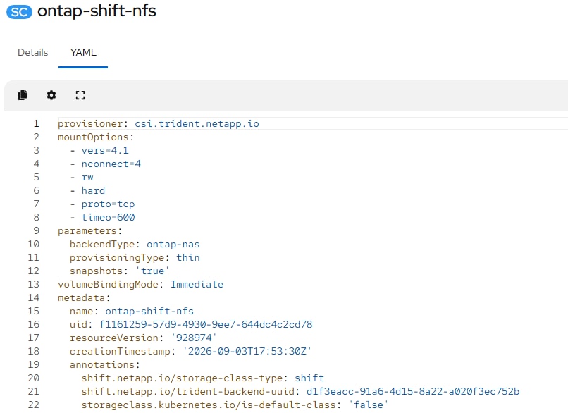
Procedure 15. Migrate VMware VMs to OpenShift Virtualization using NetApp Shift
Now that the Migration Toolkit for Virtualization Operator has been fully set up with the Shift operator, VMware VMs can be migrated to any namespace within the OpenShift cluster.
Step 1. To migrate using the Shift operator, the VMs to be migrated need to be in an NFS v3 datastore volume that is in the OpenShift SVM. To set this up, the OpenShift NFS VLAN needs to be piped into the VMware environment. If the VMware and OpenShift environments are on the same Fabric Interconnects (FIs), you simply need to add the OpenShift NFS VLAN to the VMware vDS Ethernet Network Group in Intersight and then create a new port profile for this VLAN in the VMware vDS. Then, add a VMkernel port with DHCP to each VMware ESXi Host. If the OpenShift and VMware environments are not on the same FIs, the OpenShift NFS VLAN will need to be piped across the network from the OpenShift FIs to the VMware FIs then added to the VLAN policy and Ethernet Network Group policy in the VMware FIs. If the VLAN is piped and setup correctly, the VMkernel port should obtain a DHCP IP address.
Step 2. Using NetApp System Manager, create a volume in the OpenShift SVM that is exported with NFS and is large enough to hold all VMs in the group being migrated. In this validation example, a 1 TB volume was created.
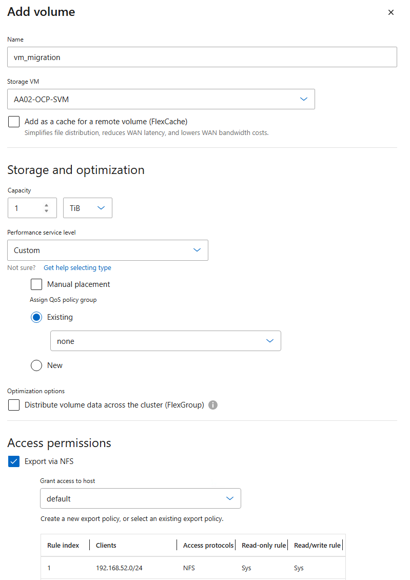
Step 3. Mount the newly created datastore volume as an NFS v3 datastore to all your VMware ESXi hosts.
Step 4. In VMware, storage migrate all VMs to be migrated to OpenShift to the newly created NFS v3 datastore.
Note: VMs can be migrated in groups, but only like VMs should be migrated in a group. Migrate Windows VMs in one group and Linux VMs in a separate group. The datastore created above can be reused for multiple migrations.
Step 5. If a new namespace is required, create the namespace. Go to Project > Create Project in the OpenShift Console. If Network Attachment Definitions are needed within the namespace, create them within the namespace or Project.
Step 6. VM Migrations must occur within the openshift-mtv namespace. Select Project > openshift-mtv in the OpenShift Console. Then choose Migration for Virtualization > Migration plans. In the upper right, click Create Plan.
Step 7. Give the plan a name, such as migrate-<vm group name>. Leave openshift-mtv as the Plan project. Select the vCenter as the source provider. Select host as the Target provider. Select the appropriate Target namespace for Target project. Click Next.
Step 8. Expand the folders and select any supported Windows or Linux VMs to migrate, taking into consideration the note above. Click Next.
Step 9. Select Use new network map and select appropriate Source and Target networks. Click Next.
Step 10. Select Use new storage map and select appropriate Source and the storage class created above for Shift, ensuring it has been annotated for NetApp Shift. Click Next.
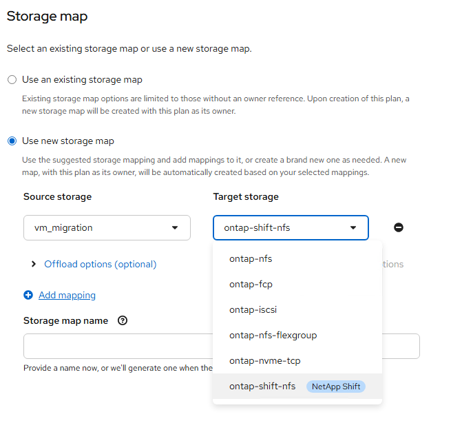
Note: It is critical that the VMs to be migrated are placed in NFS v3 datastore(s) within the OpenShift SVM if a NetApp Shift annotated storage class is used. If the VMs are not in the NFS v3 datastore(s) in the OpenShift SVM, the migration will not complete and issues could occur with NetApp Trident. Note also that if you do not select the Shift-annotated storage class, a normal OpenShift MTV migration will occur.
Step 11. Leave Cold migration selected and click Next.
Step 12. Review Other settings and click Next.
Step 13. Click Next.
Step 14. Click Next.
Step 15. Review all settings and click Create plan.
Step 16. It will take a few minutes for the migration plan to get to a Status of Ready for migration. Once the Status is Ready for migration, click Actions > Start followed by Start. Note that any running VMs will be shut down.
Step 17. To monitor the status of the VM migration, click the Virtual machines tab. Then, next to any VM, click > to monitor the migration status. Note that the disk migration takes place very quickly because of the integration with NetApp Shift. Depending on the VM disk number and size, the migration will take some time.
Step 18. Once the migration has Succeeded, select Virtualization > VirtualMachines, then select the project you migrated the VM(s) into. Select a VM that was migrated. If the VM is running, wait for any reboot cycles to complete and then Stop the VM. Select the Configuration tab and then select Network. The migration preserved the VMware MAC address. If you want to use an OpenShift MAC address, note the values of each field, then click the three dots to the right and choose Delete followed by Delete again. Then click Add network interface. Select or fill in the noted values and click Save. Now the VM should have an OpenShift MAC address.
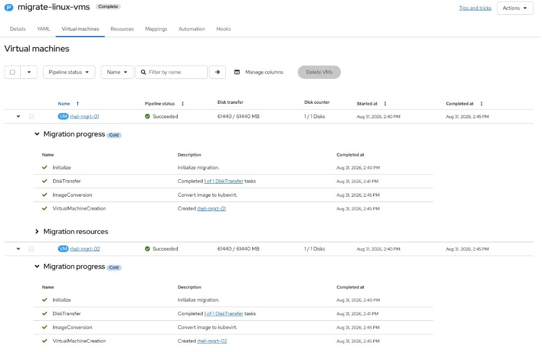
Step 19. Select Actions > Start to power on the VM. Select the Console tab to interact with the VM. The VM networking may need to be set up for the VM.
Step 20. For each VM that was migrated, select the VM under Virtual Machines and select the Configuration tab. Select Storage and note the last five characters of the PVC name. Go to NetApp System Manager and select Storage > Volumes. Use the filter and filter the Volume name to the 5 characters noted. Click the volume name. The Shift toolkit made this volume a clone of the datastore volume. Use the More menu on the upper right to select Split Clone. Select “Delete snapshots and split the clone” and click Split. Click Back to Volumes and re-select the Volume to see the clone split status. When the clone split is complete, recheck OpenShift to get the VM disk size. Divide this size by 0.95 and round up to the next GB. In System Manager, again use the More menu to select Resize. Size the volume down to the size just calculated and click Save. Repeat this process for each migrated VM disk.
Step 21. Back in VMware either delete the migrated VMs or migrate them back to a VMware datastore.
Procedure 16. Migrate an OpenShift VM to a Different Namespace and Backing Up VMs
The virtctl export command can be used to export a VM disk and VM configuration, and then the disk can be imported into a different namespace along with a modified VM configuration. This method can also be used to migrate VMs between OpenShift clusters and for VM Backup and Restore.
Step 1. A storage location will need to be set up, which is large enough to hold large numbers of VM disks. It is recommended to use the OpenShift Installer VM for this since it already contains configurations to access the OpenShift cluster. One way to set up a large storage location is to create a volume on the NetApp storage and mount it with NFS from this VM. You will need to have a network interface in the NFS VLAN to the VM and configure this interface with MTU 9000. It may not be possible to use an MTU 9000 NFS interface to the installer VM if it is outside the FlexPod and the NFS VLAN cannot be piped to it. In that case an NFS LIF in the Baremetal-MGMT VLAN can be added and an export-policy rule added to allow the mount. Once the NFS mount is setup, create a directory for each VM and switch into this directory.
Step 2. For the VM to export, if you want to leave it running, in the OpenShift Console select Virtualization > VirtualMachines. Then select the VM to export. On the right, click Take snapshot. Name the snapshot snapshot-for-export and click Save.
Step 3. On the OpenShift Installer VM from the VM backup directory, export the VM disk and VM manifest. Depending on the disk size, this can take some time:
oc project <vm-namespace>
virtctl vmexport create snapshot-for-export –-snapshot=snapshot-for-export
virtctl vmexport download snapshot-for-export –-volume=<disk pvc name> --output=disk.img.gz
virtctl vmexport download snapshot-for-export --manifest > <vm-name>.yaml
virtctl vmexport delete snapshot-for-export
Note: If the VM has more than one disk, you will need to add “—volume=<pvc name>” to the disk export command along with a disk number in the –output field and run this command once for each disk.
Step 4. Delete the snapshot from the source VM.
Step 5. Import the VM disk(s) into the new namespace. The disk(s) will be uploaded using the default Storage Class and will create a PVC with the same name as the dv:
oc project <new-vm-namespace>
virtctl image-upload dv <vm-name> --image-path=./disk.img.gz --size=<source disk size>Gi –-insecure
Note: If the VM has more than one disk, each disk will need to be uploaded to a unique PVC or DV.
Step 6. Using a text editor, edit the manifest .yaml file. Change the VM name if necessary and change the namespace to the new namespace name. Under interfaces, delete the macAddress line to set a new MAC address for this VM. If a different NAD is to be used with the new VM, change the networkName field. Next, change the persistentVolumeClaim > claimName to match the dv field in the command above. Finally, delete all the lines in the DataVolume section of the yaml file between the sets of “---” leaving only one “---” at the bottom of the file.
Step 7. Create the new VM in the new namespace:
oc create -f <vm-name>.yaml
Note: If you get an error message stating that the VM could not be created, run the command a second time and the VM should be successfully created.
Procedure 17. Attach a GPU to a VM
This procedure can be used to attach PCIe passthrough GPUs to VMs, which will pass an entire datacenter GPU in compute mode to a VM. Although it is possible to define vGPUs, which are subsets of full GPUs with a part of the GPU framebuffer, and pass through to VMs, that is not defined here. For defining and passing through vGPUs to VMs, see https://docs.redhat.com/en/documentation/openshift_container_platform/4.20/html-single/virtualization/index#virt-about-using-virtual-gpus_virt-configuring-virtual-gpus.
Step 1. Node labeling can be used to designate worker node GPUs to be used for containerized applications or for VMs. To label a node to passthrough its GPUs to VMs, from the OpenShift Installer VM, run the following command:
oc label node <node_name> nvidia.com/gpu.deploy.operands=false
Step 2. Verify that the label was added to the node:
oc describe node <node_name>
Step 3. This will cause the NVIDIA GPU operator to unload the NVIDIA GPU driver pods from that node. This can be verified with the following commands. The NVIDIA GPU Operator pods should no longer be running on the labeled node:
oc get pods -n nvidia-gpu-operator -o wide
Step 4. ssh to the node(s) with the passthrough GPU(s) and obtain the vendor-ID and the device-ID for the GPU device. In this case on the node that was labeled and has L40S GPUs, the vendor-ID is 10de and the device-ID is 26b9. On the other node that was not labeled, but has H200 GPUs, the vendor-ID is 10de and the device-ID is 233b:
ssh core@control-2
lspci -nnv | grep -i nvidia
38:00.0 3D controller [0302]: NVIDIA Corporation AD102GL [L40S] [10de:26b9] (rev a1)
Subsystem: NVIDIA Corporation Device [10de:1851]
d8:00.0 3D controller [0302]: NVIDIA Corporation AD102GL [L40S] [10de:26b9] (rev a1)
Subsystem: NVIDIA Corporation Device [10de:1851]
Kernel driver in use: nvidia
exit
ssh core@control-1
lspci -nnv | grep -i nvidia
48:00.0 3D controller [0302]: NVIDIA Corporation GH100 [H200 NVL] [10de:233b] (rev a1)
Subsystem: NVIDIA Corporation Device [10de:1996]
Kernel driver in use: nvidia
49:00.0 3D controller [0302]: NVIDIA Corporation GH100 [H200 NVL] [10de:233b] (rev a1)
Subsystem: NVIDIA Corporation Device [10de:1996]
Kernel driver in use: nvidia
exit
Step 5. In your machine-configs directory, create 100-worker-vfiopci.bu to bind the GPU(s) to the VFIO driver and substituting your GPU’s vendor-ID and device-ID:
variant: openshift
version: 4.20.0
metadata:
name: 100-worker-vfiopci
labels:
machineconfiguration.openshift.io/role: worker
storage:
files:
- path: /etc/modprobe.d/vfio.conf
mode: 0644
overwrite: true
contents:
inline: |
options vfio-pci ids=10de:26b9,10de:233b
- path: /etc/modules-load.d/vfio-pci.conf
mode: 0644
overwrite: true
contents:
inline: vfio-pci
Note: If using combination control plane / worker nodes, create a copy of this CR for the control plane with machineconfiguration.openshift.io/role: master.
Step 6. Use butane to generate a MachineConfig yaml file:
butane 100-worker-vfiopci.bu -o 100-worker-vfiopci.yaml
Note: If using combination control plane / worker nodes, create the control plane MachineConfig also.
Step 7. Apply the MachineConfig to the worker nodes to attach any unattached GPUs to the VFIO driver:
oc apply -f 100-worker-vfiopci.yaml
Note: If using combination control plane / worker nodes, create the control plane MachineConfig also.
Step 8. Verify that the MachineConfig object(s) was added:
oc get MachineConfig
Step 9. After the MachineConfig has been applied and the server rebooted, ssh back to the labeled node and verify the GPU(s) is bound to the VFIO driver:
ssh core@control-2
lspci -nnk -d 10de:
da:00.0 3D controller [0302]: NVIDIA Corporation AD102GL [L40S] [10de:26b9] (rev a1)
Subsystem: NVIDIA Corporation Device [10de:1851]
Kernel driver in use: vfio-pci
Kernel modules: nouveau
db:00.0 3D controller [0302]: NVIDIA Corporation AD102GL [L40S] [10de:26b9] (rev a1)
Subsystem: NVIDIA Corporation Device [10de:1851]
Kernel driver in use: vfio-pci
Kernel modules: nouveau
exit
Step 10. Edit the hyperconverged custom resource:
oc edit hyperconverged kubevirt-hyperconverged -n openshift-cnv
Step 11. Add the NVIDIA GPU as a permitted host device:
spec:
permittedHostDevices:
pciHostDevices:
- pciDeviceSelector: "10DE:26B9"
resourceName: "nvidia.com/NVIDIA-L40S”
Step 12. Save the changes and exit the editor with “:x” (vim save and exit).
Step 13. To attach a GPU to a VM, in the OpenShift Console select Virtualization > VirtualMachines. Then select the appropriate project. Select the VM and then select the Configuration tab. Select Hardware devices > GPU devices. Give the GPU a name then select an available GPU under Device name. You can use the Add GPU device link to add multiple GPUs to a VM. Click Save to complete adding the GPU to the VM.
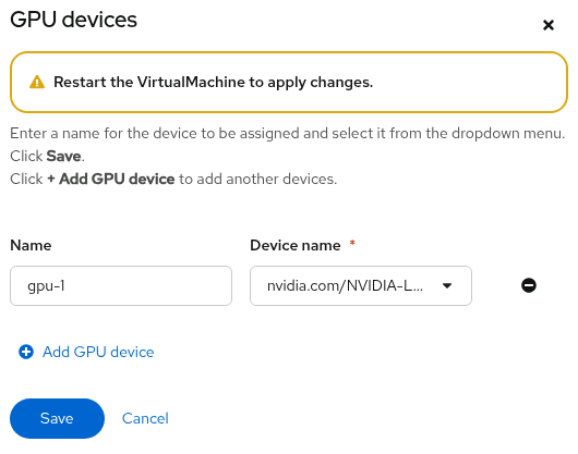
Step 14. You need to restart the VM to use the GPU. A RHEL 9 VM was used to validate the same Stable Diffusion 3.5 setup that was done using a container earlier in this document. In this case https://docs.nvidia.com/nim/large-language-models/latest/get-started/prerequisites.html was used and the CUDA SDK, NVIDIA GPU driver, Docker, and the Container Toolkit were installed. Docker was used to run the latest PyTorch container and Stable Diffusion 3.5 was then run to validate usage of the GPU.
Data Protection for VMs in OpenShift Virtualization using NetApp Trident Protect
In this section, we demonstrate the installation and configuration of Trident protect. Then, we showcase how Trident protect can be used to perform on-demand and scheduled snapshots of VMs in an OpenShift Virtualization environment, followed by restore operations.
Procedure 1. Install Trident protect on the OpenShift cluster
Step 1. If helm is not already installed on this machine, install it:
sudo dnf install helm
Note: helm is installed from the epel repository.
Step 2. From the OpenShift Installer VM, run the following command to add the Trident protect Helm repository:
helm repo add netapp-trident-protect https://netapp.github.io/trident-protect-helm-chart
Step 3. Create Trident protect namespace:
oc create namespace trident-protect
Step 4. Install Trident protect using Helm:
helm install trident-protect netapp-trident-protect/trident-protect --set clusterName=ocp-cluster --version 100.2606.0 -n trident-protect
Step 5. Check the pods output after installation:
oc get pods -n trident-protect
NAME READY STATUS RESTARTS AGE
autosupportbundle-6a67ef94-3a4e-46c3-bba6-ef974cf1eae7-vnq9z 1/1 Running 0 3h58m
trident-protect-controller-manager-85495988dc-s7pwb 1/1 Running 0 11h
Note: For detailed information about Trident protect, go to:
https://docs.netapp.com/us-en/trident/trident-protect/learn-about-trident-protect.html
Procedure 2. Install the Trident protect CLI plugin
Trident protect CLI plugin is an extension of the Trident tridentctl utility, to create and interact with Trident protect custom resources (CRs).
Step 1. Download the Trident protect CLI plugin:
curl -L -o tridentctl-protect https://github.com/NetApp/tridentctl-protect/releases/download/v26.06.0/tridentctl-protect-linux-amd64
Step 2. Enable execute permissions for the plugin binary:
chmod +x tridentctl-protect
Step 3. Copy the plugin binary to a location that is defined in your PATH variable:
sudo cp ./tridentctl-protect /usr/local/bin/
Note: Copying the plugin to a location in your PATH variable enables you to use the plugin by typing tridentctl-protect or tridentctl protect from any location.
Step 4. Check the Trident protect installed version:
tridentctl-protect version
26.06.0
Step 5. Use the help function to view usage guidance:
tridentctl-protect help
Procedure 3. Configure Trident protect AppVault for ONTAP S3
Prior to creating the snapshots and backups for a VM, an Object Storage must be configured in Trident protect to store the snapshots and backups. This is done using the bucket CR (Custom Resource). The bucket CR is known as AppVault in Trident protect. AppVault objects are the declarative Kubernetes workflow representation of a storage bucket. An AppVault CR contains the configurations necessary for a bucket to be used in protection operations, such as backups, snapshots, restore operations, and SnapMirror replication. Only administrators can create AppVaults.
Note: In this solution, we used ONTAP S3 as Object storage. Make sure you have configured ONTAP S3 object storage as described in the earlier section Configure ONTAP S3 Storage Access Using a Dedicated SVM. Keep the access Key and Secret Key in a safe location.
Step 1. When defining an AppVault CR, we need to include credentials to access the resources hosted by the provider (here ONTAP S3). On the OpenShift Installer VM, create appvault-secret.yaml and update with the access key and secret access key of ONTAP S3:
cat appvault-secret.yaml
---
apiVersion: v1
stringData:
accessKeyID: "<access key of S3>"
secretAccessKey: "<secret access key of S3>"
# you can also provide base 64 encoded values instead of string values
# data:
# base 64 encoded values
# accessKeyID: < base 64 encoded access key>
# secretAccessKey: <base 64 encoded secretAccess key>
kind: Secret
metadata:
name: appvault-secret
namespace: trident-protect
type: Opaque
Step 2. Create a secret to store the ONTAP S3 credentials:
oc create -f appvault-secret.yaml
Step 3. Create appvault.yaml and update with ONTAP S3 related info like bucket name, S3 LIF IP etc. Note that the AppVault CR needs to reside on the OpenShift cluster where Trident protect is installed:
cat appvault.yaml
---
apiVersion: protect.trident.netapp.io/v1
kind: AppVault
metadata:
name: ontap-s3-appvault
namespace: trident-protect
spec:
providerType: OntapS3
providerConfig:
s3:
bucketName: s3-bucket1
endpoint: <lif for S3 access>
secure: "false"
skipCertValidation: "true"
providerCredentials:
accessKeyID:
valueFromSecret:
key: accessKeyID
name: appvault-secret
secretAccessKey:
valueFromSecret:
key: secretAccessKey
name: appvault-secret
Step 4. Create an AppVault object for ONTAP S3:
oc create -f appvault.yaml
Step 5. View the newly created AppVault object. You can use the Trident protect CLI plugin to get information about AppVault objects that you have created on the cluster.

Procedure 4. Create VMs in OpenShift Virtualization
In this solution, we deployed four VMs, CentOS Stream 9, RHEL 9, Fedora, and Windows Server 2025 in demo namespace for validation purpose. You can choose to deploy any other VMs of your choice for solution validation. The root disk chooses the default storage class automatically, so, verify the default storage class is set appropriately. In this setup, the default storage class is ontap-nfs. Ensure that when you create the additional disk, you choose the storage class ontap-nfs and check the “Apply optimized storage settings” checkbox. This will set the Access modes to RWX and Volume Mode to Block. In this setup, VMs are created with a root disk.
The following figure shows the VMs created in demo namespace:
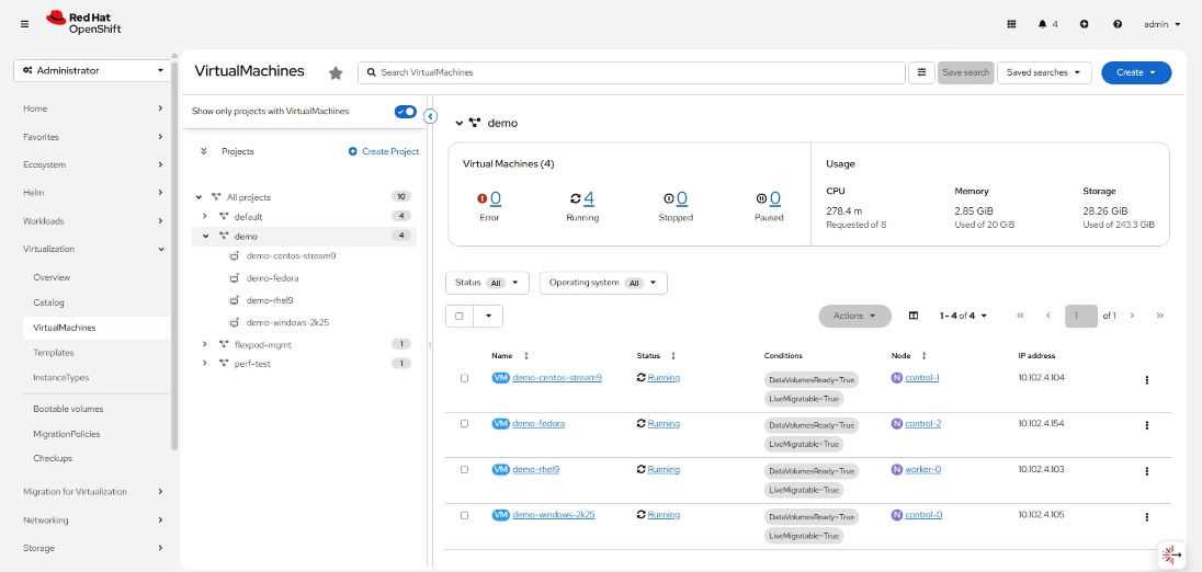
The following output shows the VMs, pods, and PVCs configured in demo namespace:
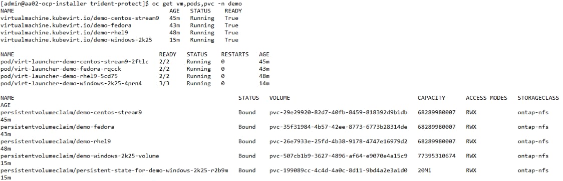
Procedure 5. Selecting specific VMs in a namespace to create snapshots and perform later restore
In this validation, we selected two VMs, RHEL 9 and Windows Server 2025 in demo namespace for which we will perform snapshots and restore in next procedures.
Step 1. Label the demo-rhel9, demo-windows-2k25 VMs, and their associated resources in the demo namespace:
oc label vms demo-rhel9 demo-windows-2k25 category=protect-rhel-win2k25-vms -n demo
oc label pvc demo-rhel9 demo-windows-2k25-volume category=protect-rhel-win2k25-vms -n demo
Step 2. Verify that the RHEL, Windows VMs, and corresponding PVCs has the labels:

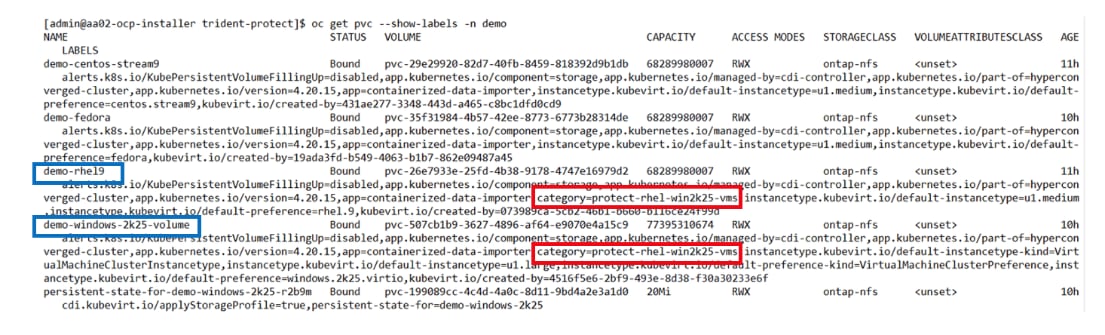
Procedure 6. Create an application for specific VMs using the label selector
You need to define an application to manage with Trident protect by creating an application CR. In this validation, we created an application for RHEL and Windows VMs using the label selector.
Step 1. Create demo-vms-app.yaml to define an application for demo-rhel9, demo-windows-2k25 VMs using label selector:
cat demo-vms-app.yaml
---
apiVersion: protect.trident.netapp.io/v1
kind: Application
metadata:
creationTimestamp: null
name: demo-vms-app
namespace: demo
spec:
includedNamespaces:
- labelSelector:
matchLabels:
category: protect-rhel-win2k25-vms
namespace: demo
status:
conditions: null
Step 2. Create Application using the above application CR file:
oc create -f demo-vms-app.yaml
Step 3. Verify the newly created application in the demo namespace:

Procedure 7. Create on-demand snapshot of specific VMs in a namespace by using corresponding application
In the previous step, an application was created using label selectors to include only the demo-rhel9 and demo-windows-2k25 VMs in the demo namespace. Now, you will create an on-demand snapshot for this application.
Step 1. Run the following command to create an on-demand snapshot for the application (demo-vms-app). Provide the ONTAP S3 AppVault name where the snapshot record will be stored:
tridentctl-protect create snapshot demo-vms-snapshot-on-demand --app demo-vms-app --appvault ontap-s3-appvault -n demo
Note: In order to create an on-demand backup for the application, run the following command:
tridentctl-protect create backup <backup_name> --appvault <appvault_name> --app <application_name> -n <application_namespace>
Step 2. Verify that the snapshot (demo-vms-snapshot-on-demand) was created successfully:

Step 3. You can also check that the snapshot record is stored in the ONTAP S3 bucket through an application like S3 Browser as shown below:
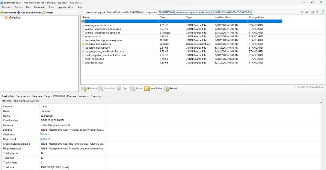
Procedure 8. Restore specific VMs to a different namespace
Restoring a VM to a different namespace allows us to move an application (and its associated resources) from one project to another, such as from a development namespace to a production namespace. You can easily create copies of a VM for testing or development purposes without impacting the production environment. You can create a replica or clone of the VM in a separate namespace for disaster recovery purposes. In this validation, you will use the on-demand snapshot created in the previous steps to restore the demo-rhel9 and demo-windows-2k25 VMs to a different namespace.
Step 1. Create a new namespace to which you want to restore the application/VMs. In this validation, the demo2 namespace was created as shown below:
oc create namespace demo2
Step 2. Create a snapshot restore object to a different namespace (demo2) from the on-demand snapshot (demo-vms-snapshot-on-demand):
tridentctl-protect create snapshotrestore <snapshot_restore_name> --snapshot <snapshot_namespace>/<snapshot_to_restore> --namespace-mapping <source_to_destination_namespace_mapping> -n <application_namespace>
tridentctl-protect create snapshotrestore demo2-vms-snaprestore --snapshot demo/demo-vms-snapshot-on-demand --namespace-mapping demo:demo2 -n demo2
Note: In order to restore a backup to a different namespace, create the backup restore object using the following command:
tridentctl-protect create backuprestore <backup_restore_name> --backup <backup_namespace/backup_to_restore> --namespace-mapping <source_to_destination_namespace_mapping> -n <application_namespace>
Step 3. Verify that the snapshot restore object demo2-vms-snaprestore was created successfully:

Step 4. Verify that the RHEL and Windows VMs have been recreated in demo2 namespace. As shown in the following figures, VMs and PVCs are restored successfully:

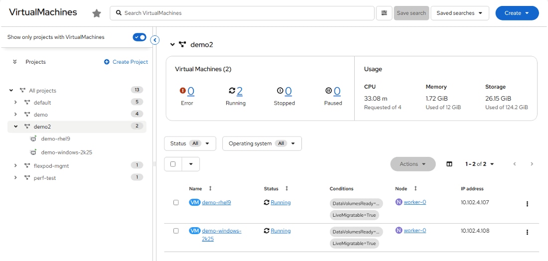
Procedure 9. Create a data protection schedule for VMs
A protection policy protects an application/VM by creating snapshots, backups, or both at a defined schedule. You can choose to create snapshots and backups hourly, daily, weekly, and monthly, and can specify the number of copies to retain. In this validation, we will create schedule-based snapshots for the application demo-vms-app.
Step 1. Create the custom resource (CR) file snapshot-schedule-demo-vms.yaml to configure the schedule for the snapshots. Specify the granularity and the number of snapshots to be retained.
Note: The following snapshot schedule CR creates a daily snapshot of the demo-vms-app application at 14:30 UTC. The snapshots are stored in the specified AppVault (ontap-s3-appvault), and a retention policy is applied to keep the most recent two snapshots, ensuring efficient storage utilization.
cat snapshot-schedule-demo-vms.yaml
---
apiVersion: protect.trident.netapp.io/v1
kind: Schedule
metadata:
creationTimestamp: null
name: snapshot-schedule-daily
namespace: demo
spec:
appVaultRef: ontap-s3-appvault
applicationRef: demo-vms-app
backupRetention: "0"
dayOfMonth: ""
dayOfWeek: ""
enabled: true
granularity: Daily
hour: "14"
minute: "30"
recurrenceRule: ""
snapshotRetention: "2"
status: {}
Note: Customers can also configure weekly snapshot schedules by defining appropriate schedule parameters to run at a specific day and time each week. This is achieved by setting the granularity parameter to Weekly, specifying the desired execution day using the dayOfWeek parameter, and defining the schedule time using the hour and minute parameters, while keeping dayOfMonth empty as it is not applicable. For example, to configure a snapshot every Sunday at 02:30 UTC, the schedule would use granularity: Weekly, dayOfWeek: Sunday, hour: "2", and minute: "30". This configuration ensures that a snapshot is created once per week at the defined time, and retention parameters can be adjusted as needed to control how many weekly snapshots are preserved.
Step 2. Create snapshot schedule in the demo namespace using the below command:
oc create -f snapshot-schedule-demo-vms.yaml
Note: You can also create the snapshot schedule using the CLI method as shown below:
tridentctl-protect create schedule <schedule_name> --app <name_of_app_to_snapshot> --appvault <appvault_name> --granularity <frequency_to_run> --day-of-month <day_of_month_to_run_schedule> --day-of-week <day_of_week_to_run_schedule> --hour <hour_of_day_to_run> --minute <minute_of_hour_to_run> --snapshot-retention <how_many_snapshots_to_retain> --backup-retention 0 --recurrence-rule <recurrence> -n <application_namespace>
tridentctl-protect create schedule snapshot-schedule-daily --app demo-vms-app --appvault ontap-s3-appvault --granularity Daily --hour 14 --minute 30 --backup-retention 0 --snapshot-retention 2 -n demo
Note: The following command can be used to create a backup schedule:
tridentctl-protect create schedule <schedule_name> --app <name_of_app_to_backup> --appvault <appvault_name> --granularity <frequency_to_run> --day-of-month <day_of_month_to_run_schedule> --day-of-week <day_of_week_to_run_schedule> --hour <hour_of_day_to_run> --minute <minute_of_hour_to_run> --backup-retention <how_many_backups_to_retain> --recurrence-rule <recurrence> -n <application_namespace>
Step 3. Verify the newly created schedule snapshot-schedule-daily is in place as shown below:

Step 4. View the snapshots created for the demo-vms-app application. Based on the schedule, two snapshot copies are retained as shown below:

Step 5. You can also verify that the scheduled snapshots are stored successfully in the ONTAP S3 bucket using an application like S3 browser as shown below:
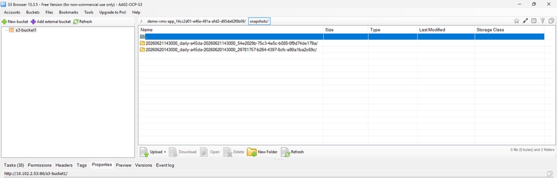
Procedure 10. Restore the VMs from the snapshot to the same namespace
In the event of any disaster, if a VM is compromised or gets corrupted, you can use the backup or snapshot to restore the VM to the original namespace. In this validation, we will use one of the snapshots created in previous steps to restore the demo-rhel9 and demo-windows-2k25 VMs to the demo (original) namespace.
Step 1. Simulate a disaster by deleting the specific VMs (demo-rhel9 and demo-windows-2k25) from the demo namespace:
oc delete vms demo-rhel9 demo-windows-2k25 -n demo
Step 2. Verify that the RHEL, Windows VMs, and their associated resources (PVCs) are deleted from the demo namespace:

Step 3. Create the CR file vm-demo-snapshotinplacerestore.yaml to configure the snapshot-in-place-restore object from the snapshot of the VMs:
cat vm-demo-snapshotinplacerestore.yaml
---
apiVersion: protect.trident.netapp.io/v1
kind: SnapshotInplaceRestore
metadata:
creationTimestamp: null
name: demo-vms-restore-from-snapshot
namespace: demo
spec:
appArchivePath: demo-vms-app_14cc2d01-e46a-491a-afd2-d95da62f8b09/snapshots/20260621143000_daily-a45da-20260621143000_54e2029b-75c3-4e5c-b085-0f9d74de179a
appVaultRef: ontap-s3-appvault
resourceFilter: {}
status:
conditions: null
postRestoreExecHooksRunResults: null
state: ""
Note: You can run the following command to find the value for “appArchivePath” field in the above YAML manifest:
oc describe snapshot <name of snapshot> -n <namespace> | grep “App Archive Path”
oc describe snapshot daily-a45da-20260621143000 -n demo | grep "App Archive Path"
App Archive Path: demo-vms-app_14cc2d01-e46a-491a-afd2-d95da62f8b09/snapshots/20260621143000_daily-a45da-20260621143000_54e2029b-75c3-4e5c-b085-0f9d74de179a
Step 4. Create the snapshot-in-place-restore object in the demo namespace using the following command:
oc create -f vm-demo-snapshotinplacerestore.yaml
Note: You can also create the snapshot-in-place-restore object using the CLI method as shown below:
tridentctl-protect create snapshotinplacerestore <restore_name> --snapshot <namespace/snapshot_to_restore> -n <application_namespace>
tridentctl-protect create snapshotinplacerestore demo-vms-restore-from-snapshot --snapshot demo/daily-a45da-20260621143000 -n demo
Note: The following command can be used to create backup-in-place-restore object as shown below:
tridentctl-protect create backupinplacerestore <restore_name> --backup <namespace/backup_to_restore> -n <application_namespace>
Step 5. Verify the newly created snapshot-in-place-restore object (demo-vms-restore-from-snapshot) as shown below:

Step 6. Verify that the RHEL and Windows VMs (demo-rhel9 and demo-windows-2k25), and their corresponding PVCs are restored to the demo namespace as shown in the following figures:
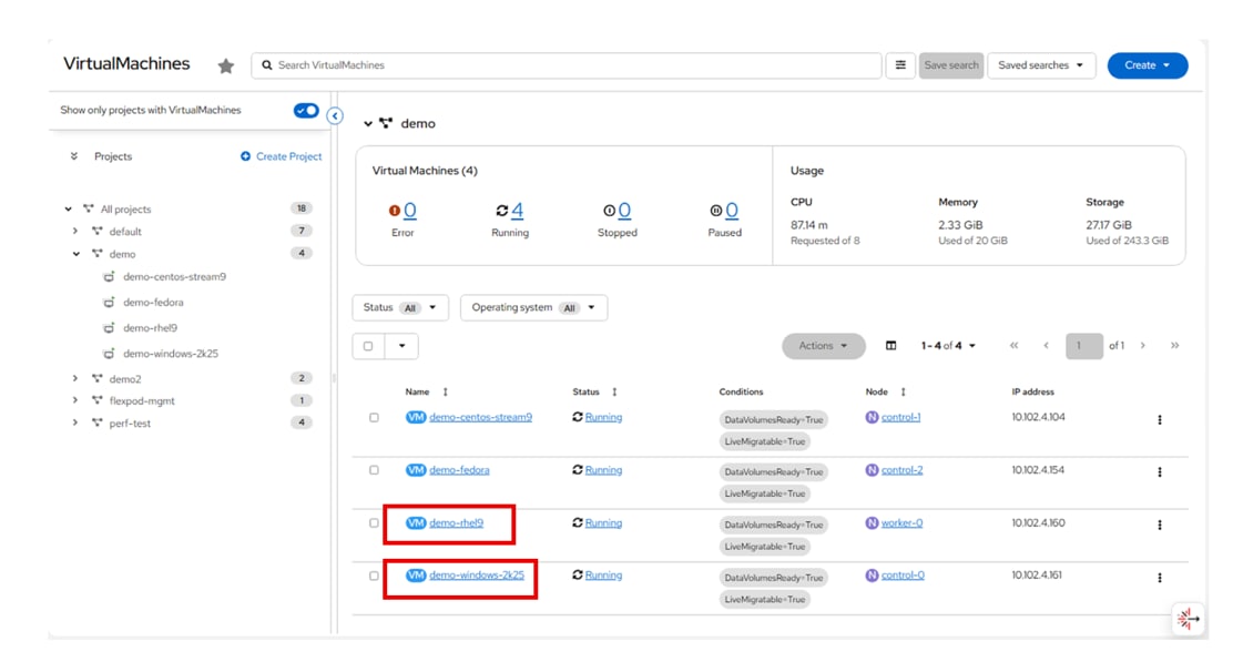
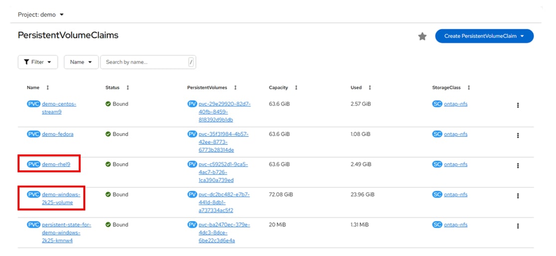
John George, Technical Marketing Engineer, Cisco Systems, Inc.
John has been involved in designing, developing, validating, and supporting the FlexPod Converged Infrastructure since it was developed. John has validated many solutions on FlexPod, including AI Inferencing, Secure Multi-Tenancy, Red Hat OpenShift with Virtualization, VMware vSphere, and Microsoft Windows Hyper-V. John holds a master’s degree in Computer Engineering from Clemson University.
Kamini Singh, Technical Marketing Engineer, Hybrid Cloud Infra & OEM Solutions, NetApp
Kamini Singh is a Technical Marketing engineer at NetApp. She has seven years of experience in data center infrastructure solutions. Kamini focuses on FlexPod hybrid cloud infrastructure solution design, implementation, validation, automation, and sales enablement. Kamini holds a bachelor’s degree in Electronics and Communication and a master’s degree in Communication Systems.
Acknowledgements
For their support and contribution to the design, validation, and creation of this Cisco Validated Design, the authors would like to thank:
● Archana Sharma, Principal Technical Marketing Engineer, Cisco Systems, Inc.
● Paniraja Koppa, Technical Marketing Engineer, Cisco Systems, Inc.
● Eldho Jacob, Leader, Product Management, Cisco Systems, Inc.
Appendix
This appendix contains the following:
● Cisco Nexus Switch Manual Configuration
Cisco Nexus Switch Manual Configuration
Procedure 1. Create Tenant VLANs on Cisco Nexus A and Cisco Nexus B
Step 1. Log into both Nexus switches as admin using SSH.
Step 2. Configure the OpenShift Bare Metal VLAN:
config t
vlan <bm-vlan-id for example, 1022>
name <tenant-name, for example, AA02-OCP>-BareMetal-MGMT
Step 3. Configure the VM Network VLAN and the Live Migration VLAN:
vlan <vm-net-vlan-id for example, 1024>
name <tenant-name>-VM-Net
vlan <live-migration-vlan-id for example, 3002>
name <tenant-name>-Live Migration
exit
Step 4. If configuring NVMe-TCP storage access, create the following two additional VLANs:
vlan <nvme-tcp-a-vlan-id for example, 3032>
name <tenant-name>-NVMe-TCP-A
vlan <nvme-tcp-b-vlan-id for example, 3042>
name <tenant-name>-NVMe-TCP-B
exit
Step 5. Add OpenShift NFS VLAN:
vlan <nfs-vlan-id for example, 3052>
name <tenant-name>-NFS
Step 6. Add VLANs to the vPC peer link in both Nexus switches:
int Po10
switchport trunk allowed vlan add <bm-vlan-id>,<vm-net-vlan-id>,<live-migration-vlan-id>,<nvme-tcp-a-vlan-id>,<nvme-tcp-b-vlan-id>,<nfs-vlan-id>
Step 7. Add VLANs to the storage interfaces in both Nexus switches:
int Po11,Po12
switchport trunk allowed vlan add <bm-vlan-id>,<nvme-tcp-a-vlan-id>,<nvme-tcp-b-vlan-id>,<nfs-vlan-id>
Step 8. Add VLANs to the UCS Fabric Interconnect Uplink interfaces in both Nexus switches:
int Po15,Po16
switchport trunk allowed vlan add <bm-vlan-id>,<vm-net-vlan-id>,<live-migration-vlan-id>,<nvme-tcp-a-vlan-id>,<nvme-tcp-b-vlan-id>,<nfs-vlan-id>
Step 9. Add the Bare Metal VLAN to the Switch Uplink interface in both Nexus switches:
interface Po124
switchport trunk allowed vlan add <bm-vlan-id>
exit
Step 10. Add Tenant VRF and L3 interfaces in Cisco Nexus A:
vrf context <tenant-name>
ip route 0.0.0.0/0 <bm-subnet-gateway>
exit
interface Vlan<bm-vlan-id>
no shutdown
vrf member <tenant-name>
ip address <bm-switch-a-ntp-distr-ip>/<bm-vlan-mask-length>
hsrp version 2
hsrp <unique HSRP ID>
preempt
ip <bm-switch-gateway>
exit
ip dhcp relay address <first DHCP Server IP>
ip dhcp relay address <second DHCP Server IP>
exit
interface Vlan<vm-net-vlan-id>
no shutdown
vrf member <tenant-name>
ip address <vm-net-switch-a-ntp-distr-ip>/<vm-net-vlan-mask-length>
hsrp version 2
hsrp <unique HSRP ID>
preempt
ip <vm-net-switch-gateway>
exit
ip dhcp relay address <first DHCP Server IP>
ip dhcp relay address <second DHCP Server IP>
exit
interface Vlan<nvme-tcp-a-vlan-id>
no shutdown
vrf member <tenant-name>
ip address <nvme-tcp-a-switch-a-ntp-distr-ip>/<nvme-tcp-a-vlan-mask-length>
hsrp version 2
hsrp <unique HSRP ID>
preempt
ip <nvme-tcp-a-switch-gateway>
exit
ip dhcp relay address <first DHCP Server IP>
ip dhcp relay address <second DHCP Server IP>
exit
interface Vlan<nvme-tcp-b-vlan-id>
no shutdown
vrf member <tenant-name>
ip address <nvme-tcp-b-switch-a-ntp-distr-ip>/<nvme-tcp-b-vlan-mask-length>
hsrp version 2
hsrp <unique HSRP ID>
preempt
ip <nvme-tcp-b-switch-gateway>
exit
ip dhcp relay address <first DHCP Server IP>
ip dhcp relay address <second DHCP Server IP>
exit
interface Vlan<nfs-vlan-id>
no shutdown
vrf member <tenant-name>
ip address <nfs-switch-a-ntp-distr-ip>/<nfs-vlan-mask-length>
hsrp version 2
hsrp <unique HSRP ID>
preempt
ip <nfs-switch-gateway>
exit
ip dhcp relay address <first DHCP Server IP>
ip dhcp relay address <second DHCP Server IP>
exit
copy run start
Step 11. Add Tenant VRF and L3 Interfaces in Cisco Nexus B:
vrf context <tenant-name>
ip route 0.0.0.0/0 <bm-subnet-gateway>
exit
interface Vlan<bm-vlan-id>
no shutdown
vrf member <tenant-name>
ip address <bm-switch-b-ntp-distr-ip>/<bm-vlan-mask-length>
hsrp version 2
hsrp <unique HSRP ID>
preempt
priority 120
ip <bm-switch-gateway>
exit
ip dhcp relay address <first DHCP Server IP>
ip dhcp relay address <second DHCP Server IP>
exit
interface Vlan<vm-net-vlan-id>
no shutdown
vrf member <tenant-name>
ip address <vm-net-switch-b-ntp-distr-ip>/<vm-net-vlan-mask-length>
hsrp version 2
hsrp <unique HSRP ID>
preempt
priority 120
ip <vm-net-switch-gateway>
exit
ip dhcp relay address <first DHCP Server IP>
ip dhcp relay address <second DHCP Server IP>
exit
interface Vlan<nvme-tcp-a-vlan-id>
no shutdown
vrf member <tenant-name>
ip address <nvme-tcp-a-switch-b-ntp-distr-ip>/<nvme-tcp-a-vlan-mask-length>
hsrp version 2
hsrp <unique HSRP ID>
preempt
priority 120
ip <nvme-tcp-a-switch-gateway>
exit
ip dhcp relay address <first DHCP Server IP>
ip dhcp relay address <second DHCP Server IP>
exit
interface Vlan<nvme-tcp-b-vlan-id>
no shutdown
vrf member <tenant-name>
ip address <nvme-tcp-b-switch-b-ntp-distr-ip>/<nvme-tcp-b-vlan-mask-length>
hsrp version 2
hsrp <unique HSRP ID>
preempt
priority 120
ip <nvme-tcp-b-switch-gateway>
exit
ip dhcp relay address <first DHCP Server IP>
ip dhcp relay address <second DHCP Server IP>
exit
interface Vlan<nfs-vlan-id>
no shutdown
vrf member <tenant-name>
ip address <nfs-switch-b-ntp-distr-ip>/<nfs-vlan-mask-length>
hsrp version 2
hsrp <unique HSRP ID>
preempt
priority 120
ip <nfs-switch-gateway>
exit
ip dhcp relay address <first DHCP Server IP>
ip dhcp relay address <second DHCP Server IP>
exit
copy run start
Step 12. The following commands can be used to see the switch configuration and status:
show run
show vpc
show vlan
show port-channel summary
show ntp peer-status
show cdp neighbors
show lldp neighbors
show run int
show int
show udld neighbors
show int status
CVD Program
ALL DESIGNS, SPECIFICATIONS, STATEMENTS, INFORMATION, AND RECOMMENDATIONS (COLLECTIVELY, "DESIGNS") IN THIS MANUAL ARE PRESENTED "AS IS," WITH ALL FAULTS. CISCO AND ITS SUPPLIERS DISCLAIM ALL WARRANTIES, INCLUDING, WITHOUT LIMITATION, THE WARRANTY OF MERCHANTABILITY, FITNESS FOR A PARTICULAR PURPOSE AND NONINFRINGEMENT OR ARISING FROM A COURSE OF DEALING, USAGE, OR TRADE PRACTICE. IN NO EVENT SHALL CISCO OR ITS SUPPLIERS BE LIABLE FOR ANY INDIRECT, SPECIAL, CONSEQUENTIAL, OR INCIDENTAL DAMAGES, INCLUDING, WITHOUT LIMITATION, LOST PROFITS OR LOSS OR DAMAGE TO DATA ARISING OUT OF THE USE OR INABILITY TO USE THE DESIGNS, EVEN IF CISCO OR ITS SUPPLIERS HAVE BEEN ADVISED OF THE POSSIBILITY OF SUCH DAMAGES.
THE DESIGNS ARE SUBJECT TO CHANGE WITHOUT NOTICE. USERS ARE SOLELY RESPONSIBLE FOR THEIR APPLICATION OF THE DESIGNS. THE DESIGNS DO NOT CONSTITUTE THE TECHNICAL OR OTHER PROFESSIONAL ADVICE OF CISCO, ITS SUPPLIERS OR PARTNERS. USERS SHOULD CONSULT THEIR OWN TECHNICAL ADVISORS BEFORE IMPLE-MENTING THE DESIGNS. RESULTS MAY VARY DEPENDING ON FACTORS NOT TESTED BY CISCO.
CCDE, CCENT, Cisco Eos, Cisco Lumin, Cisco Nexus, Cisco StadiumVision, Cisco TelePresence, Cisco WebEx, the Cisco logo, DCE, and Welcome to the Human Network are trademarks; Changing the Way We Work, Live, Play, and Learn and Cisco Store are service marks; and Access Registrar, Aironet, AsyncOS, Bringing the Meeting To You, Catalyst, CCDA, CCDP, CCIE, CCIP, CCNA, CCNP, CCSP, CCVP, Cisco, the Cisco Certified Internetwork Expert logo, Cisco IOS, Cisco Press, Cisco Systems, Cisco Systems Capital, the Cisco Systems logo, Cisco Unified Computing System (Cisco UCS), Cisco UCS B-Series Blade Servers, Cisco UCS C-Series Rack Servers, Cisco UCS S-Series Storage Servers, Cisco UCS X-Series, Cisco UCS Manager, Cisco UCS Management Software, Cisco Unified Fabric, Cisco Application Centric Infrastructure, Cisco Nexus 9000 Series, Cisco Nexus 7000 Series. Cisco Prime Data Center Network Manager, Cisco NX-OS Software, Cisco MDS Series, Cisco Unity, Collaboration Without Limitation, EtherFast, EtherSwitch, Event Center, Fast Step, Follow Me Browsing, FormShare, GigaDrive, HomeLink, Internet Quotient, IOS, iPhone, iQuick Study, LightStream, Linksys, MediaTone, MeetingPlace, MeetingPlace Chime Sound, MGX, Networkers, Networking Academy, Network Registrar, PCNow, PIX, PowerPanels, ProConnect, ScriptShare, SenderBase, SMARTnet, Spectrum Expert, StackWise, The Fastest Way to Increase Your Internet Quotient, TransPath, WebEx, and the WebEx logo are registered trade-marks of Cisco Systems, Inc. and/or its affiliates in the United States and certain other countries. (LDW_P1)
All other trademarks mentioned in this document or website are the property of their respective owners. The use of the word partner does not imply a partnership relationship between Cisco and any other company. (0809R)
