Performance Tuning Guide for Cisco UCS M5 Servers White Paper
Available Languages
Bias-Free Language
The documentation set for this product strives to use bias-free language. For the purposes of this documentation set, bias-free is defined as language that does not imply discrimination based on age, disability, gender, racial identity, ethnic identity, sexual orientation, socioeconomic status, and intersectionality. Exceptions may be present in the documentation due to language that is hardcoded in the user interfaces of the product software, language used based on RFP documentation, or language that is used by a referenced third-party product. Learn more about how Cisco is using Inclusive Language.
The Basic Input and Output System (BIOS) tests and initializes the hardware components of a system and boots the operating system from a storage device. A typical computational system has several BIOS settings that control the system’s behavior. Some of these settings are directly related to the performance of the system.
This document explains the BIOS settings that are valid for the Cisco Unified Computing System™ (Cisco UCS®) M5 server generation (Cisco UCS B200 and B480 M5 Blade Servers and C220, C240, and C480 M5 Rack Servers) using Intel® Xeon® Scalable processor family CPUs. It describes how to optimize the BIOS settings to meet requirements for the best performance and energy efficiency for the Cisco UCS M5 generation of blade and rack servers.
This document also discusses the BIOS settings that can be selected for various workload types on Cisco UCS M5 servers that use Intel Xeon Scalable processor family CPUs. Understanding the BIOS options will help you select appropriate values to achieve optimal system performance.
This document does not discuss the BIOS options for specific firmware releases of Cisco UCS servers. The settings demonstrated here are generic.
The process of setting performance options in your system BIOS can be daunting and confusing, and some of the options you can choose are obscure. For most options, you must choose between optimizing a server for power savings or for performance. This document provides some general guidelines and suggestions to help you achieve optimal performance from your Cisco UCS blade and rack servers that use Intel Xeon Scalable processor family CPUs.
This document focuses on two main scenarios: how to tune the BIOS for high performance and how to tune it for low latency.
With the latest multiprocessor, multicore, and multithreading technologies in conjunction with current operating systems and applications, today's Cisco UCS servers based on the Intel Xeon Scalable processor deliver the highest levels of performance, as demonstrated by the numerous industry-standard benchmark publications from the Standard Performance Evaluation Corporation (SPEC), SAP, and the Transaction Processing Performance Council (TPC).
Cisco UCS servers with standard settings already provide an optimal ratio of performance to energy efficiency. However, through BIOS settings you can further optimize the system with higher performance and less energy efficiency. Basically, this optimization operates all the components in the system at the maximum speed possible and prevents the energy-saving options from slowing down the system. In general, optimization to achieve greater performance is associated with increased consumption of electrical power. This document explains how to configure the BIOS settings to achieve optimal computing performance.
The BIOS offers a variety of options to reduce latency. In some cases, the corresponding application does not make efficient use of all the threads available in the hardware. To improve performance, you can disable threads that are not needed (hyperthreading) or even cores in the BIOS to reduce the small fluctuations in the performance of computing operations that especially occur in some High-Performance Computing (HPC) applications and analytical database applications. Furthermore, by disabling cores that are not needed, you can improve turbo-mode performance in the remaining cores under certain operating conditions.
However, other scenarios require performance that is as constant as possible. Although the current generation of Intel processors delivers better turbo-mode performance than the preceding generation, the maximum turbo-mode frequency is not guaranteed under certain operating conditions. In such cases, disabling the turbo mode can help prevent changes in frequency.
Energy-saving functions, whose aim is to save energy whenever possible through frequency and voltage reduction and through the disabling of certain function blocks and components, also have a negative impact on response time. The higher the settings for the energy saving modes, the lower the performance. Furthermore, in each energy-saving mode, the processor requires a certain amount of time to change back from reduced performance to maximum performance.
This document explains how to configure the power and energy saving modes to reduce system latency. The optimization of server latency, particularly in an idle state, results in substantially greater consumption of electrical power.
This section describes the options you can configure in the Cisco UCS BIOS.
This section describes processor options you can configure.
Enhanced Intel SpeedStep Technology
Intel SpeedStep Technology is designed to save energy by adjusting the CPU clock frequency up or down depending on how busy the system is. Intel Turbo Boost Technology provides the capability for the CPU to adjust itself to run higher than its stated clock speed if it has enough power to do so.
You can specify whether the processor uses Enhanced Intel SpeedStep Technology, which allows the system to dynamically adjust processor voltage and core frequency. This technology can result in decreased average power consumption and decreased average heat production.
The setting can be one of the following:
● Disabled: The processor never dynamically adjusts its voltage or frequency.
● Enabled: The processor uses Enhanced Intel SpeedStep Technology and enables all supported processor sleep states to further conserve power.
Intel Turbo Boost Technology
Intel Turbo Boost Technology depends on Intel SpeedStep: if you want to enable Intel Turbo Boost, you must enable Intel SpeedStep first. If you disable Intel SpeedStep, you lose the capability to use Intel Turbo Boost.
Intel Turbo Boost is especially useful for latency-sensitive applications and for scenarios in which the system is nearing saturation and would benefit from a temporary increase in the CPU speed. If your system is not running at this saturation level and you want the best performance at a utilization rate of less than 90 percent, you should disable Intel SpeedStep to help ensure that the system is running at its stated clock speed at all times.
Intel Hyper-Threading Technology
You can specify whether the processor uses Intel Hyper-Threading Technology, which allows multithreaded software applications to process threads in parallel within each processor. You should test the CPU hyperthreading option both enabled and disabled in your specific environment. If you are running a single-threaded application, you should disable hyperthreading.
The setting can be one of the following:
● Disabled: The processor does not permit hyperthreading.
● Enabled: The processor allows parallel processing of multiple threads.
Core multiprocessing and latency-sensitive single-threaded applications
The core multiprocessing option is designed to enable the user to disable cores. This option may affect the pricing of certain software packages that are licensed by the core. You should consult your software license and software vendor about whether disabling cores qualifies you for any particular pricing policies. Set core multiprocessing to All if pricing policy is not an issue for you.
For latency-sensitive single-threaded applications, you can optimize performance by disabling unnecessary cores, disabling hyperthreading, enabling all C-states, enabling Intel SpeedStep, and enabling Intel Turbo Boost. With this configuration, the remaining cores often will benefit from higher turbo speeds and better use of the shared Layer 3 cache.
CPU performance
Intel Xeon processors have several layers of cache. Each core has a tiny Layer 1 cache, sometimes referred to as the Data Cache Unit (DCU), that has 32 KB for instructions and 32 KB for data. Slightly bigger is the Layer 2 cache, with 256 KB shared between data and instructions for each core. In addition, all cores on a chip share a much larger Layer 3 cache, which is about 10 to 45 MB in size (depending on the processor model and number of cores).
The prefetcher settings provided by Intel primarily affect the Layer 1 and Layer 2 caches on a processor core (Table 1). You will likely need to perform some testing with your individual workload to find the combination that works best for you. Testing on the Intel Xeon Scalable processor has shown that most applications run best with all prefetchers enabled. See Tables 2 and 3 for guidance.
Table 1. CPU performance and prefetch options from Intel
| Performance option |
Cache affected |
| Hardware prefetcher |
Layer 2 |
| Adjacent-cache-line prefetcher |
Layer 2 |
| DCU prefetcher |
Layer 1 |
| DCU instruction pointer (DCU-IP) prefetcher |
Layer 1 |
Table 2. Cisco UCS CPU performance options
| Option |
Description |
| CPU performance |
Sets the CPU performance profile for the server. This can be one of the following:
● Enterprise: All prefetchers are enabled.
● High throughput: DCU IP prefetcher are enabled, and all other prefetchers are disabled.
● HPC: All prefetchers are enabled. This setting is also known as HPC.
● Platform default: The BIOS uses the value for this attribute contained in the BIOS defaults for the server type and vendor.
|
Table 3. Cisco UCS CPU prefetcher options and target benchmarks and workloads
| Prefetchers |
Target benchmarks and workloads |
| All enabled |
HPC benchmarks, web server, SAP application server, virtualization, and TPC-E |
| DCU-IP enabled; all others disabled |
SPECjbb2005 and certain server-side Java application-server applications |
Hardware prefetcher
The hardware prefetcher prefetches additional streams of instructions and data into the Layer 2 cache upon detection of an access stride. This behavior is more likely to occur during operations that sort through sequential data, such as database table scans and clustered index scans, or that run a tight loop in code.
You can specify whether the processor allows the Intel hardware prefetcher to fetch streams of data and instructions from memory into the unified second-level cache when necessary.
The setting can be one of the following:
● Disabled: The hardware prefetcher is not used.
● Enabled: The processor uses the hardware prefetcher when cache problems are detected.
Adjacent-cache-line prefetcher
The adjacent-cache-line prefetcher always prefetches the next cache line. Although this approach works well when data is accessed sequentially in memory, it can quickly litter the small Layer 2 cache with unneeded instructions and data if the system is not accessing data sequentially, causing frequently accessed instructions and code to leave the cache to make room for the adjacent-line data or instructions.
You can specify whether the processor fetches cache lines in even or odd pairs instead of fetching just the required line.
The setting can be one of the following:
● Disabled: The processor fetches only the required line.
● Enabled: The processor fetches both the required line and its paired line.
DCU streamer prefetcher
Like the hardware prefetcher, the DCU streamer prefetcher prefetches additional streams of instructions or data upon detection of an access stride; however, it stores the streams in the tiny Layer 1 cache instead of the Layer 2 cache.
This prefetcher is a Layer 1 data cache prefetcher. It detects multiple loads from the same cache line that occur within a time limit. Making the assumption that the next cache line is also required, the prefetcher loads the next line in advance to the Layer 1 cache from the Layer 2 cache or the main memory.
The setting can be one of the following:
● Disabled: The processor does not try to anticipate cache read requirements and fetches only explicitly requested lines.
● Enabled: The DCU prefetcher analyzes the cache read pattern and prefetches the next line in the cache if it determines that it may be needed.
DCU-IP prefetcher
The DCU-IP prefetcher predictably prefetches data into the Layer 1 cache on the basis of the recent instruction pointer load instruction history.
You can specify whether the processor uses the DCU-IP prefetch mechanism to analyze historical cache access patterns and preload the most relevant lines in the Layer 1 cache.
The setting can be one of the following:
● Disabled: The processor does not preload any cache data.
● Enabled: The DCU-IP prefetcher preloads the Layer 1 cache with the data it determines to be the most relevant.
Low-level cache prefetch
This BIOS option configures the processor’s Last-Level Cache (LLC) prefetch feature as a result of the noninclusive cache architecture. The LLC prefetcher exists on top of other prefetchers that can prefetch data into the core DCU and Mid-Level Cache (MLC). In some cases, setting this option to disabled can improve performance.
The setting for this BIOS option can be one of the following:
● Disabled: The LLC prefetcher is disabled. The other core prefetchers are not affected.
● Enabled: The core prefetcher can prefetch data directly to the LLC.
By default, the LLC prefetch option is disabled.
Direct cache access
The Direct-Cache Access (DCA) mechanism is a system-level protocol in a multiprocessor system to improve I/O network performance, thereby providing higher system performance. The basic goal is to reduce cache misses when a demand read operation is performed. This goal is accomplished by placing the data from the I/O devices directly into the CPU cache through hints to the processor to perform a data prefetch operation and install the data in its local caches.
Execute Disable Bit feature
The Intel Execute Disable Bit feature classifies memory areas on the server to specify where the application code can run. As a result of this classification, the processor disables code processing if a malicious worm attempts to insert code in the buffer. This setting helps prevent damage, worm propagation, and certain classes of malicious buffer overflow attacks.
The setting can be one of the following:
● Disabled: The processor does not classify memory areas.
● Enabled: The processor classifies memory areas.
Intel VT for Directed I/O
You can specify whether the processor uses Intel Virtualization Technology (VT) for Directed I/O (VT-d), which allows a platform to run multiple operating systems and applications in independent partitions.
The setting can be one of the following:
● Disabled: The processor does not permit virtualization.
● Enabled: The processor allows multiple operating systems in independent partitions.
Note: If you change this option, you must power the server off and on before the setting takes effect.
Enables you to configure the CPU power management settings for the following options:
● Enhanced Intel Speedstep Technology
● Intel Turbo Boost Technology
● Processor Power State C6
For best performance, set the power technology option to Performance or Custom. If it is not set to Custom, the individual settings for Intel SpeedStep and Turbo Boost and the C6 power state are ignored.
This option can be set to one of the following:
● Custom: The server uses the individual settings for the BIOS parameters in the preceding section. You must select this option if you want to change any of these BIOS parameters.
● Performance: The server determines the best settings for the BIOS parameters and provides optimal CPU power performance in the preceding section.
● Disabled: The server does not perform any CPU power management, and any settings for the BIOS parameters in the preceding section are ignored.
● Energy Efficient: The server determines the best settings for the BIOS parameters in the preceding section and ignores the individual settings for these parameters.
You can set the processor C-states.
Processor C1E
Enabling the C1E option allows the processor to transition to its minimum frequency upon entering the C1 state. This setting does not take effect until after you have rebooted the server. When this option is disabled, the CPU continues to run at its maximum frequency in the C1 state. Users should disable this option to perform application benchmarking.
You can specify whether the CPU transitions to its minimum frequency when entering the C1 state.
The setting can be one of the following:
● Disabled: The CPU continues to run at its maximum frequency in the C1 state.
● Enabled: The CPU transitions to its minimum frequency. This option saves the maximum amount of power in the C1 state.
Processor C3 report
You can specify whether the BIOS sends the C3 report to the operating system. When the OS receives the report, it can transition the processor into the lower C3 power state to decrease energy use while maintaining optimal processor performance.
The setting can be one of the following:
● Disabled: The BIOS does not send the C3 report.
● Enabled: The BIOS sends the C3 report, allowing the OS to transition the processor to the C3 low-power state.
Processor C6 report
The C6 state is power-saving halt and sleep state that a CPU can enter when it is not busy. Unfortunately, it can take some time for the CPU to leave these states and return to a running condition. If you are concerned about performance (for all but latency-sensitive single-threaded applications), and if you can do so, disable anything related to C-states.
You can specify whether the BIOS sends the C6 report to the operating system. When the OS receives the report, it can transition the processor into the lower C6 power state to decrease energy use while maintaining optimal processor performance.
The setting can be one of the following:
● Disabled: The BIOS does not send the C6 report.
● Enabled: The BIOS sends the C6 report, allowing the OS to transition the processor to the C6 low-power state.
P-state coordination
You can define the way that the BIOS communicates the P-state support model to the operating system. Three models are available, as defined by the Advanced Configuration and Power Interface (ACPI) specification:
● HW_ALL: The processor hardware is responsible for coordinating the P-state among logical processors with dependencies (all the logical processors in a package).
● SW_ALL: The OS Power Manager (OSPM) is responsible for coordinating the P-state among logical processors with dependencies (all the logical processors in a physical package) and must initiate the transition on all the logical processors.
● SW_ANY: The OSPM is responsible for coordinating the P-state among logical processors with dependencies (all the logical processors in a package) and can initiate the transition on any of the logical processors in the domain.
Note: The power technology option must be set to Custom; otherwise, the server ignores the setting for this parameter.
Package C-state limit
When power technology is set to Custom, use this option to configure the lowest processor idle power state (C-state). The processor automatically transitions into package C-states based on the core C-states to which cores on the processor have transitioned. The higher the package C-state, the lower the power use of that idle package state. The default setting, Package C6 (nonretention), is the lowest power idle package state supported by the processor.
You can specify the amount of power available to the server components when they are idle.
The possible settings are as follows:
● C0/C1 State: When the CPU is idle, the system slightly reduces the power consumption. This option requires less power than C0 and allows the server to return quickly to high-performance mode.
● C2 State: When the CPU is idle, the system reduces power consumption more than with the C1 option. This option requires less power than C1 or C0, but the server takes slightly longer to return to high-performance mode.
● C6 Nonretention: When the CPU is idle, the system reduces the power consumption more than with the C3 option. This option saves more power than C0, C1, or C3, but the system may experience performance problems until the server returns to full power.
● C6 Retention: When the CPU is idle, the system reduces power consumption more than with the C3 option. This option consumes slightly more power than the C6 Nonretention option, because the processor is operating at Pn voltage to reduce the package’s C-state exit latency.
You can specify whether system performance or energy efficiency is more important on this server.
The setting can be one of the following:
● Performance: The server provides all server components with full power at all times. This option maintains the highest level of performance and requires the greatest amount of power.
● Balanced Performance: The server provides all server components with enough power to keep a balance between performance and power.
● Balanced Energy: The server provides all server components with enough power to keep a balance between performance and power.
● Energy Efficient: The server provides all server components with less power to reduce power consumption.
Note: Power Technology must be set to Custom or the server ignores the setting for this parameter
Autonomous Core C-state
When the operating system requests CPU core C1 state, system hardware automatically changes the request to core C6 state
This BIOS switch allows 2 options: "Enabled" and "Disabled".
● Enabled: HALT and C1 request get converted to C6 requests in hardware.
● Disabled: only C0 and C1 are used by the OS. C1 gets enabled automatically when an OS autohalts.
By default, Autonomous Core C-state is disabled.
You can configure workload optimization.
You can configure the following options:
● Balanced
● I/O Sensitive
● Non-Uniform Memory Access (NUMA)
● Uniform Memory Access (UMA)
By default, I/O Sensitive is enabled.
You can use several settings to optimize memory performance.
Memory reliability, availability, and serviceability configuration
Always set the memory reliability, availability, and serviceability (RAS) configuration to Maximum Performance for systems that require the highest performance and do not require memory fault-tolerance options.
The following settings are available:
● Maximum Performance: System performance is optimized.
● Mirror Mode 1LM (one-level memory): System reliability is optimized by using half the system memory as backup.
Note: For the optimal balance of performance and system stability it is recommended to use “Platform Default” (ADDDC Sparing enabled) for the Memory RAS configuration. ADDDC Sparing will incur a small performance penalty. If maximum performance is desired independently of system stability the “Maximum-Performance” Memory RAS setting can be used.
Non-uniform memory access
Most modern operating systems, particularly virtualization hypervisors, support NUMA because in the latest server designs, a processor is attached to a memory controller: therefore, half the memory belongs to one processor, and half belongs to the other processor. If a core needs to access memory that resides in another processor, a longer latency period is needed to access that part of memory. Operating systems and hypervisors recognize this architecture and are designed to reduce such trips. For hypervisors such as those from VMware and for modern applications designed for NUMA, keep this option enabled.
Integrated memory controller interleaving
The Integrated Memory Controller (IMC) BIOS option controls the interleaving between the integrated memory controllers. There are two integrated memory controllers per CPU socket in a x86 server running Intel Xeon scalable processors. If integrated memory controller Interleaving is set to 2-way, addresses will be interleaved between the two-integrated memory controller. If integrated memory controller interleaving is set to 1-way, there will be no interleaving.
Note: If Sub-NUMA Clustering (SNC) is disabled, integrated memory controller interleaving should be set to Auto. If SNC is enabled, integrated memory controller interleaving should be set to 1-way.
The following settings are available:
● 1-way Interleave: There is no interleaving.
● 2-way Interleave: Addresses are interleaved between the two integrated memory controllers.
● Auto: The CPU determines the integrated memory controller interleaving mode.
Sub-NUMA clustering
The SNC BIOS option provides localization benefits similar to the Cluster-on-Die (CoD) option, without some of the disadvantages of CoD. SNC breaks the LLC into two disjointed clusters based on address range, with each cluster bound to a subset of the memory controllers in the system. SNC improves average latency to the LLC and memory. SNC is a replacement for the CoD feature found in previous processor families. For a multisocket system, all SNC clusters are mapped to unique NUMA domains. Integrated memory controller interleaving must be set to the correct value to correspond with the SNC setting.
The setting for this BIOS option can be one of the following:
● Disabled: The LLC is treated as one cluster when this option is disabled.
● Enabled: The LLC capacity is used more efficiently and latency is reduced as a result of the core and integrated memory controller proximity. This setting may improve performance on NUMA-aware operating systems.
Note: If SNC is disabled, integrated memory controller interleaving should be set to Auto. If SNC is enabled, integrated memory controller interleaving should be set to 1-way.
Xtended Partition Table prefetch
The XPT prefetcher exists on top of other prefetchers that that can prefetch data in the core DCU, MLC, and LLC. The XPT prefetcher will issue a speculative DRAM read request in parallel to an LLC lookup. This prefetch bypasses the LLC, saving latency. You can specify whether the processor uses the XPT prefetch mechanism to fetch the date into the XPT.
The setting can be one of the following:
● Disabled: The processor does not preload any cache data.
● Enabled: The XPT prefetcher preloads the Layer 1 cache with the data it determines to be the most relevant.
Intel UltraPath Interconnect prefetch
Intel UltraPath Interconnect (UPI) prefetch is a mechanism to get the memory read started early on a Double-Data-Rate (DDR) bus.
The setting can be one of the following:
● Disabled: The processor does not preload any cache data.
● Enabled: The UPI prefetcher preloads the Layer 1 cache with the data it determines to be the most relevant.
ADDDC Sparing
Adaptive Double Device Data Correction (ADDDC) is a memory RAS feature that enables dynamic mapping of failing DRAM by monitoring corrected errors and taking action before uncorrected errors can occur and cause an outage. It is now enabled by default.
After ADDDC sparing remaps a memory region, the system could incur marginal memory latency and bandwidth penalties on memory bandwidth intense workloads that target the impacted region. Cisco recommends scheduling proactive maintenance to replace a failed DIMM after an ADDDC RAS fault is reported.
Patrol scrub
You can specify whether the system actively searches for, and corrects, single-bit memory errors even in unused portions of the memory on the server.
The setting can be one of the following:
● Disabled: The system checks for memory Error-Correcting Code (ECC) errors only when the CPU reads or writes a memory address.
● Enabled: The system periodically reads and writes memory searching for ECC errors. If any errors are found, the system attempts to fix them. This option may correct single-bit errors before they become multiple-bit errors, but it may adversely affect performance when the patrol-scrub process is running.
Demand scrub
Demand scrub occurs when the memory controller reads memory for data or instructions and the demand scrubbing logic detects a correctable error. Correct data is forwarded to the memory controller and written to memory.
With demand scrubbing disabled, the data being read into the memory controller will be corrected by the ECC logic, but no write to main memory occurs. Because the data is not corrected in memory, subsequent read operations to the same data will need to be corrected.
Configuring the BIOS for optimized CPU hardware power management
This section summarizes the BIOS settings you can configure to optimize CPU power management. It presents the settings optimized for maximum performance, low latency, and energy efficiency, summarized in Table 4.
Table 4. BIOS recommendations for maximum performance, low latency, and energy efficiency.
| BIOS Options |
BIOS Values (platform-default) |
Maximum Performance |
Low-Latency |
Energy Efficiency |
| Processor Configuration |
||||
| Intel SpeedStep Technology |
Enabled |
Platform Default |
Platform Default |
Platform Default |
| Intel Hyper-Threading Tech |
Enabled |
Platform Default |
Disabled |
Platform Default |
| Intel Virtualization Technology (VT) |
Enabled |
Disabled |
Disabled |
Platform Default |
| Intel VT for Directed I/O |
Enabled |
Disabled |
Disabled |
Platform Default |
| CPU performance |
Custom |
Platform Default |
Platform Default |
Platform Default |
| LLC Prefetch |
Disabled |
Platform Default |
Platform Default |
Platform Default |
| Direct cache access |
Enabled |
Platform Default |
Platform Default |
Platform Default |
| Advanced Power Management Configuration |
||||
| Power technology |
Energy-Efficient |
Custom |
Custom |
Custom |
| Intel Turbo Boost |
Enabled |
Platform Default |
Platform Default |
Disabled |
| P-STATE coordination |
HW_ALL |
Platform Default |
Platform Default |
Platform Default |
| Energy Performance |
Balanced Performance |
Performance |
Platform Default |
Platform Default |
| Processor C State |
Enabled |
Disabled |
Disabled |
Platform Default |
| Processor C1E |
Enabled |
Disabled |
Disabled |
Platform Default |
| Processor C3 |
Enabled |
Disabled |
Disabled |
Disabled |
| Processor C6 |
Enabled |
Disabled |
Disabled |
Platform Default |
| Processor C7 |
Enabled |
Disabled |
Disabled |
Disabled |
| Package C State limit |
C0/C1 State |
Platform Default |
Platform Default |
C6 Retention |
| Energy Performance Tuning |
OS |
Platform Default |
Platform Default |
Platform Default |
| CPU hardware power mgmt |
HWPW Native Mode |
Platform Default |
Platform Default |
Platform Default |
| Workload Configuration |
I/O Sensitive |
Balanced |
Balanced |
Platform Default |
| Autonomous Core C-State |
Disabled |
Platform Default |
Platform Default |
Enabled |
| Memory & UPI Configuration |
||||
| NUMA Optimized |
Enabled |
Platform Default |
Platform Default |
Platform Default |
| IMC Interleaving |
Auto |
1-way Interleave |
Platform Default |
Platform Default |
| XPT Prefetch |
Auto |
Platform Default |
Platform Default |
Platform Default |
| UPI Prefetch |
Enabled |
Platform Default |
Platform Default |
Platform Default |
| Sub Numa Clustering |
Disabled |
Enabled |
Platform Default |
Platform Default |
| Memory RAS configuration |
ADDDC Sparing |
Platform Default |
Platform Default |
Platform Default |
| ADDDC Sparing |
Enabled |
Platform Default |
Platform Default |
Platform Default |
Fan control policy
Fan control policies enable you to control the fan speed to reduce server power consumption and noise levels. Prior to the fan policies, the fan speed increased automatically when the temperature of any server component exceeded the set threshold. To help ensure that the fan speeds were low, the threshold temperatures of components were usually set to high values. Although this behavior suited most server configurations, it did not address the following situations:
● Maximum CPU performance: For high performance, certain CPUs must be cooled substantially below the set threshold temperature. This cooling requires very high fan speeds, which results in increased power consumption and noise levels.
● Low power consumption: To help ensure the lowest power consumption, fans must run very slowly and, in some cases, stop completely on servers that allow this behavior it. But slow fan speeds can cause servers to overheat. To avoid this situation, you need to run fans at a speed that is moderately faster than the lowest possible speed.
Following are the fan policies that you can choose:
● Balanced: This is the default policy. This setting can cool almost any server configuration, but it may not be suitable for servers with PCI Express (PCIe) cards, because these cards overheat easily.
● Low Power: This setting is well suited for minimal-configuration servers that do not contain any PCIe cards.
● High Power: This setting can be used for server configurations that require fan speeds ranging from 60 to 85 percent. This policy is well suited for servers that contain PCIe cards that easily overheat and have high temperatures. The minimum fan speed set with this policy varies for each server platform, but it is approximately in the range of 60 to 85 percent.
● Maximum Power: This setting can be used for server configurations that require extremely high fan speeds ranging between 70 and 100 percent. This policy is well suited for servers that contain PCIe cards that easily overheat and have extremely high temperatures. The minimum fan speed set with this policy varies for each server platform, but it is approximately in the range of 70 to 100 percent.
Note: This policy is configurable for standalone Cisco UCS C-Series M5 servers using the Cisco® Integrated Management Controller (IMC) console and the Cisco IMC supervisor. CIMC Web console Ò Compute Ò Power Policies Ò Configured Fan Policy.
For UCS Managed C series servers, it is configurable using Power Control Policies under. Servers Ò Policies Ò root Ò Power control Policies Ò Create Fan Power Control Policy Ò Fan speed Policy.
Operating system tuning guidance for best performance
You can tune the OS to achieve the best performance.
For Linux, set the following:
● x86_energy_perf_policy performance
When energy performance tuning is set to OS, the OS controls the Energy Performance Bias (EPB) policy. The EPB features controlled by the policy are Intel Turbo Boost override, memory clock enable (CKE), memory Output Status Register (OSR), Intel QuickPath Interconnect (QPI) L0p, C-state demotion, and I/O bandwidth P-limit. The default OSPM profile is set to Performance, which will not sacrifice performance to save energy.
● cpupower frequency-set -governor performance
The performance governor forces the CPU to use the highest possible clock frequency. This frequency is statically set and will not change. Therefore, this particular governor offers no power-savings benefit. It is suitable only for hours of heavy workload, and even then, only during times in which the CPU is rarely (or never) idle. The default setting is On Demand, which allows the CPU to achieve maximum clock frequency when the system load is high, and the minimum clock frequency when the system is idle. Although this setting allows the system to adjust power consumption according to system load, it does so at the expense of latency from frequency switching.
● Edit /etc/init.d/grub.conf to set intel_pstate=disable
Intel_pstate is a part of the CPU performance scaling subsystem in the Linux kernel (CPUFreq). It is a power scaling driver is used automatically on later generations of Intel processors. This driver takes priority over other drivers and is built-in as opposed to being a module. You can force pstate off by appending intel_pstate=disable to the kernel arguments (edit /etc/default/grub)
● tuned-adm profile latency-performance
The tuned-adm tool allows users to easily switch among a number of profiles that have been designed to enhance performance for specific use cases.
You can apply the tuned-admin server profile for typical latency performance tuning. It disables the tuned and ktune power-saving mechanisms. The CPU speed mode changes to Performance. The I/O elevator is changed to Deadline for each device. The cpu_dma_latency parameter is registered with a value of 0 (the lowest possible latency) for power management QoS to limit latency where possible.
Use the following Linux tools to measure maximum turbo frequency and power states:
● Turbostat: Turbostat is provided in the kernel-tools package. It reports on processor topology, frequency, idle power-state statistics, temperature, and power use on Intel 64 processors. It is useful for identifying servers that are inefficient in terms of power use or idle time. It also helps identify the rate of System Management Interrupts (SMIs) occurring on the system, and it can be used to verify the effects of power management tuning. Use this setting:
turbostat -S
● Intel PTUmon: The Intel Performance Tuning Utility (PTU) is a cross-platform performance analysis tool set. In addition to such traditional capabilities as tools to identify the hottest modules and functions of the application, track call sequences, and identify performance-critical source code, Intel PTU has new, more powerful data collection, analysis, and visualization capabilities. Intel PTU offers processor hardware event counters for in-depth analysis of the memory system performance, architectural tuning, and other features. Use this setting:
ptumon -l -i 5000
Refer the following resources for more information about OS performance tuning:
● Microsoft Windows and Hyper-V tuning is straightforward: set the power policy to High Performance. See:
◦ Performance Tuning Guidelines for Microsoft Windows Server 2012 R2
◦ Performance Tuning Guidelines for Microsoft Windows Server 2016
● VMware ESXi tuning is straightforward as well: set the power policy to High Performance. See:
● To tune Citrix XenServer, set xenpm set-scaling-governor performance. See:
◦ https://support.citrix.com/article/CTX200390
● To tune Red Hat Enterprise Linux, set CPU power to Performance. See:
● To tune SUSE Enterprise Linux, set CPU power to Performance. See:
◦ https://www.suse.com/documentation/sles-12/pdfdoc/book_sle_tuning/book_sle_tuning.pdf
BIOS recommendations for various workload types
This document discusses BIOS settings for the following types of workloads:
● Online transaction processing (OLTP)
● Virtualization
● High-Performance Computing (HPC)
● Java Enterprise Edition (Java EE) application server
● Analytics database Decision-Support System (DSS)
Table 5 summarizes the BIOS options and settings available for various workloads.
Table 5. BIOS options for various workloads
| BIOS Options |
BIOS Values (platform-default) |
Online Transaction Processing (OLTP) |
Virtualization |
High-Performance Computing (HPC) |
Java Application Servers |
Analytic Database Systems (DSS) |
| Processor Configuration |
||||||
| Intel SpeedStep Technology |
Enabled |
Platform Default |
Platform Default |
Platform Default |
Platform Default |
Platform Default |
| Intel Hyper-Threading Tech |
Enabled |
Platform Default |
Platform Default |
Disabled |
Platform Default |
Platform Default |
| Intel Virtualization Technology (VT) |
Enabled |
Platform Default |
Platform Default |
Disabled |
Disabled |
Platform Default |
| Intel VT for Directed I/O |
Enabled |
Platform Default |
Platform Default |
Disabled |
Disabled |
Disabled |
| CPU performance |
Custom |
Platform Default |
Platform Default |
Platform Default |
Platform Default |
Platform Default |
| LLC Prefetch |
Disabled |
Platform Default |
Platform Default |
Platform Default |
Platform Default |
Platform Default |
| Direct cache access |
Enabled |
Platform Default |
Platform Default |
Platform Default |
Platform Default |
Platform Default |
| Advanced Power Management Configuration |
||||||
| Power technology |
Energy-Efficient |
Custom |
Custom |
Platform Default |
Custom |
Custom |
| Intel Turbo Boost |
Enabled |
Platform Default |
Platform Default |
Platform Default |
Platform Default |
Platform Default |
| P-STATE coordination |
HW_ALL |
Platform Default |
Platform Default |
Platform Default |
Platform Default |
Platform Default |
| Energy Performance |
Balanced Performance |
Platform Default |
Platform Default |
Platform Default |
Platform Default |
Platform Default |
| Processor C State |
Enabled |
Disabled |
Disabled |
Platform Default |
Disabled |
Disabled |
| Processor C1E |
Enabled |
Disabled |
Disabled |
Platform Default |
Disabled |
Disabled |
| Processor C3 |
Enabled |
Disabled |
Disabled |
Platform Default |
Disabled |
Disabled |
| Processor C6 |
Enabled |
Disabled |
Disabled |
Platform Default |
Disabled |
Disabled |
| Processor C7 |
Enabled |
Disabled |
Disabled |
Platform Default |
Disabled |
Disabled |
| Package C State limit |
C0/C1 State |
Platform Default |
Platform Default |
Platform Default |
Platform Default |
Platform Default |
| Energy Performance Tuning |
OS |
Platform Default |
Platform Default |
Platform Default |
Platform Default |
Platform Default |
| CPU hardware power mgmt |
HWPW Native Mode |
Platform Default |
Platform Default |
Platform Default |
Platform Default |
Platform Default |
| Workload Configuration |
I/O Sensitive |
Platform-default |
Platform Default |
Balanced |
Platform Default |
Platform-default |
| Autonomous Core C-State |
Disabled |
Platform-default |
Platform-default |
Platform-default |
Platform-default |
Platform-default |
| Memory & UPI Configuration |
||||||
| NUMA Optimized |
Enabled |
Platform Default |
Platform Default |
Platform Default |
Platform Default |
Platform Default |
| IMC Interleaving |
Auto |
Platform Default |
Platform Default |
Platform Default |
Platform Default |
Platform Default |
| XPT Prefetch |
Auto |
Platform Default |
Platform Default |
Platform Default |
Platform Default |
Platform Default |
| UPI Prefetch |
Enabled |
Platform Default |
Platform Default |
Platform Default |
Platform Default |
Platform Default |
| Sub Numa Clustering |
Disabled |
Platform Default |
Platform Default |
Platform Default |
Platform Default |
Platform Default |
| Memory RAS configuration |
ADDDC Sparing |
Platform Default |
Platform Default |
Platform Default |
Platform Default |
Platform Default |
| ADDDC Sparing |
Enabled |
Platform Default |
Platform Default |
Platform Default |
Platform Default |
Platform Default |
The following sections describe the BIOS tuning recommendations for all the workloads listed in Table 5.
Online transaction processing workloads
OLTP systems contain the operational data needed to control and run important transactional business tasks. These systems are characterized by their ability to complete various concurrent database transactions and process real-time data. They are designed to provide optimal data processing speed.
OLTP systems are often decentralized to avoid single points of failure. Spreading the work over multiple servers can also support greater transaction processing volume and reduce response time.
Processor and memory settings for Cisco UCS managed servers: OLTP
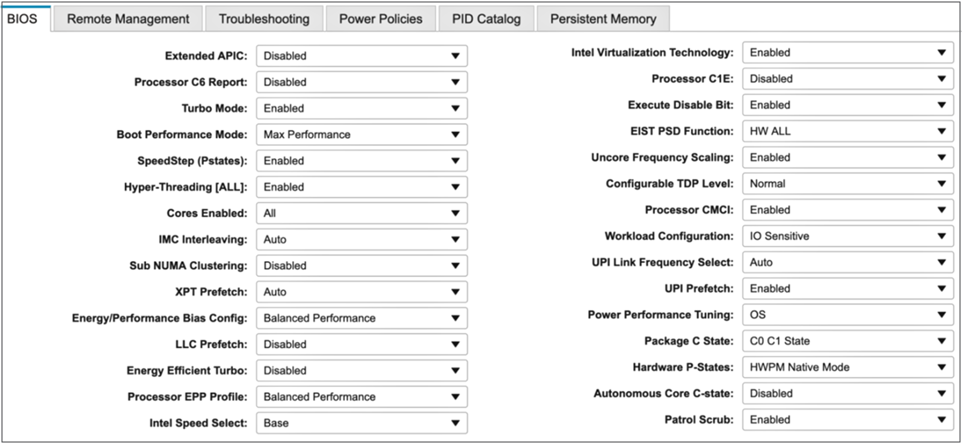
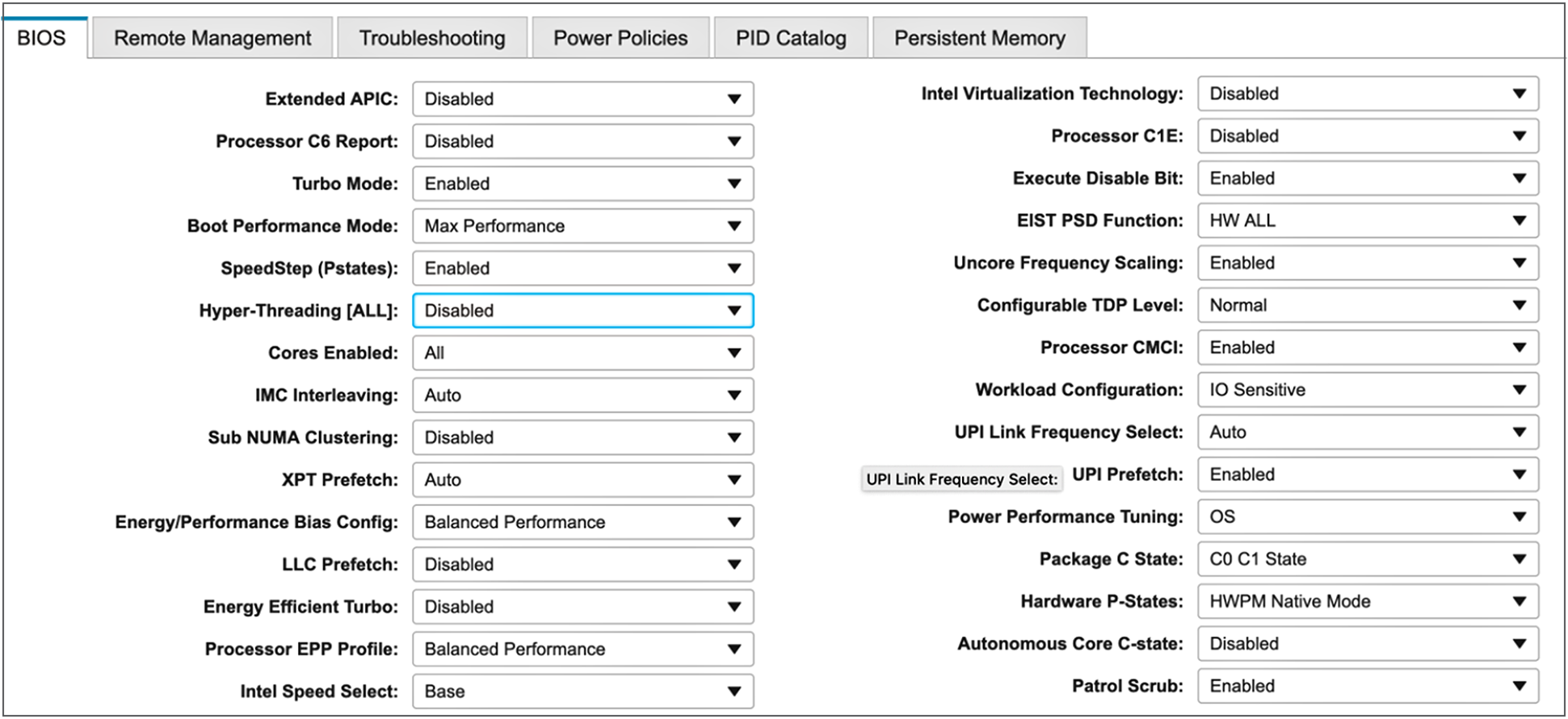
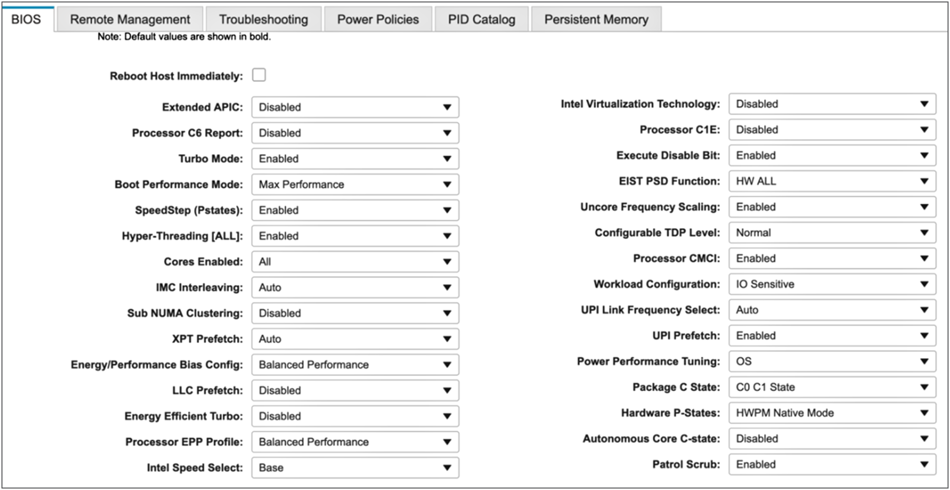
Obtaining peak performance requires some system-level tuning. Figure 1 Highlights the BIOS selections that are recommended for optimizing OLTP workloads on Cisco UCS M5 platforms managed by Cisco UCS Manager. Rest of the BIOS settings are configured as “Platform Default”.
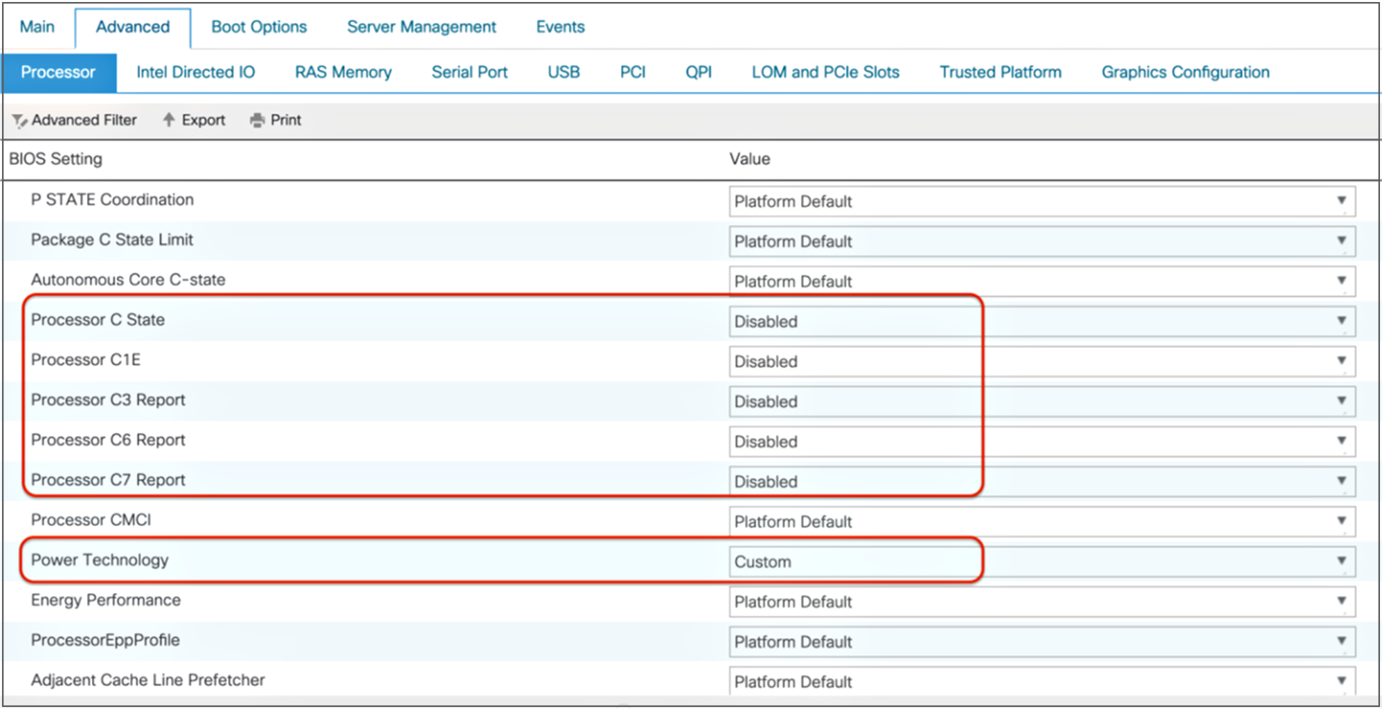
Processor settings for OLTP workloads
The Intel Turbo Boost and SpeedStep technologies are powerful management features that adjust the CPU voltage and frequency settings to optimize performance and power consumption dynamically. During periods of low CPU consumption, Intel SpeedStep can reduce the CPU frequency by reducing power consumption. Intel Turbo Boost increases the processing speed to accommodate higher demand in situations in which CPU utilization is extremely high. Each core has 20 to 30 percent more processing capability when Intel Turbo Boost is enabled. For example, the Cisco UCS M5 platforms installed with the Intel Xeon Scalable Platinum 8168 CPU operates at a base frequency of 2.7 GHz. If Intel Turbo Boost is enabled, the system can achieve frequencies as high as 3.7 GHz.
When you tune for consistent performance for OLTP applications on a system that does not run at close to 100 percent CPU utilization, you should enable Intel SpeedStep and Turbo Boost and disable C-states. Although this configuration foregoes power savings during idle times, it keeps all CPU cores running at a consistent speed and delivers the most consistent and predictable performance.
Enabling Intel Hyper-Threading Technology helps OLTP systems handle I/O-intensive workloads by allowing the processing of multiple threads per CPU core. OLTP applications typically are multithreaded, with each thread performing a small amount of work that may include I/O operations. A large number of threads results in a considerable amount of context switching, but with Intel Hyper-Threading, the effect of context switching is reduced. When Intel Direct Cache Access is enabled (Figure 2), the I/O controller places data directly into the CPU cache to reduce the cache misses while processing OLTP workloads. This approach results in improved application performance.

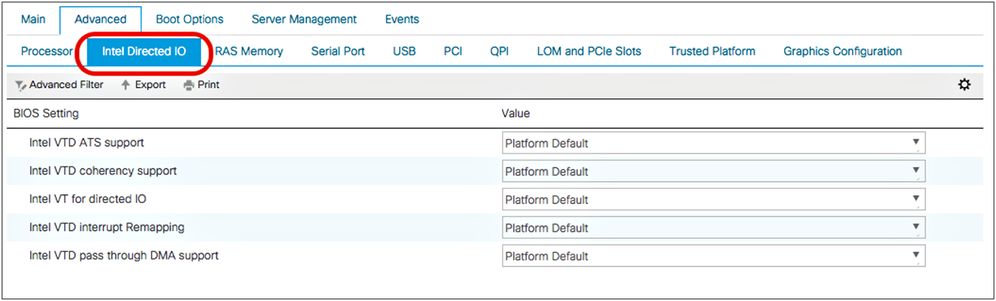
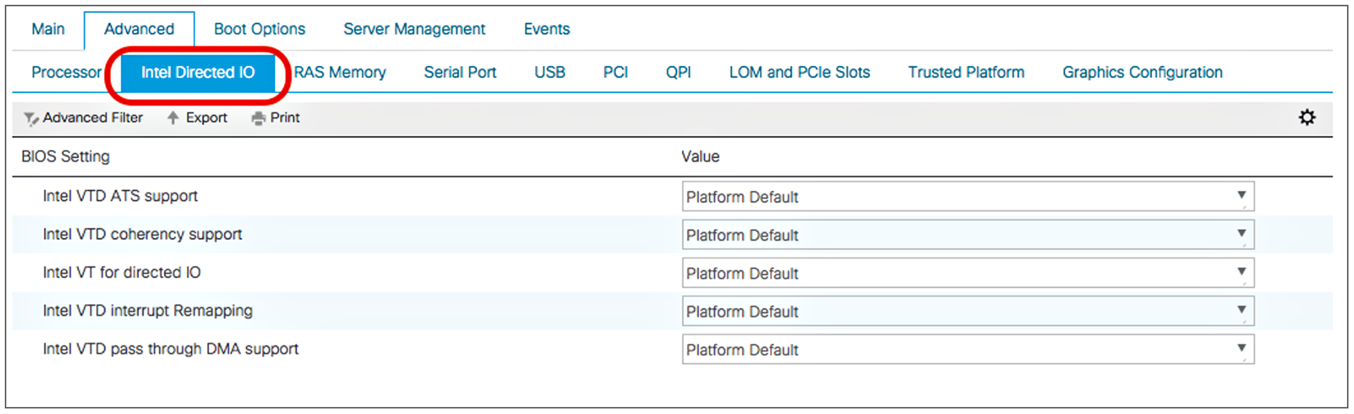
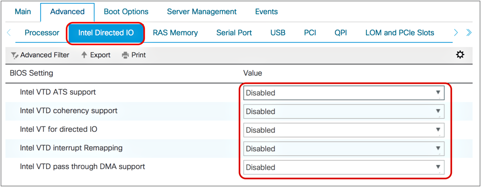
Intel Directed I/O settings for OLTP workloads
If you are deploying the system in a virtualized environment and the OLTP application uses a directed I/O path, make sure that the VT for Directed IO option is enabled. By default, these options are enabled.
Note: This feature is applicable only if the OLTP system is running in a virtualized environment.
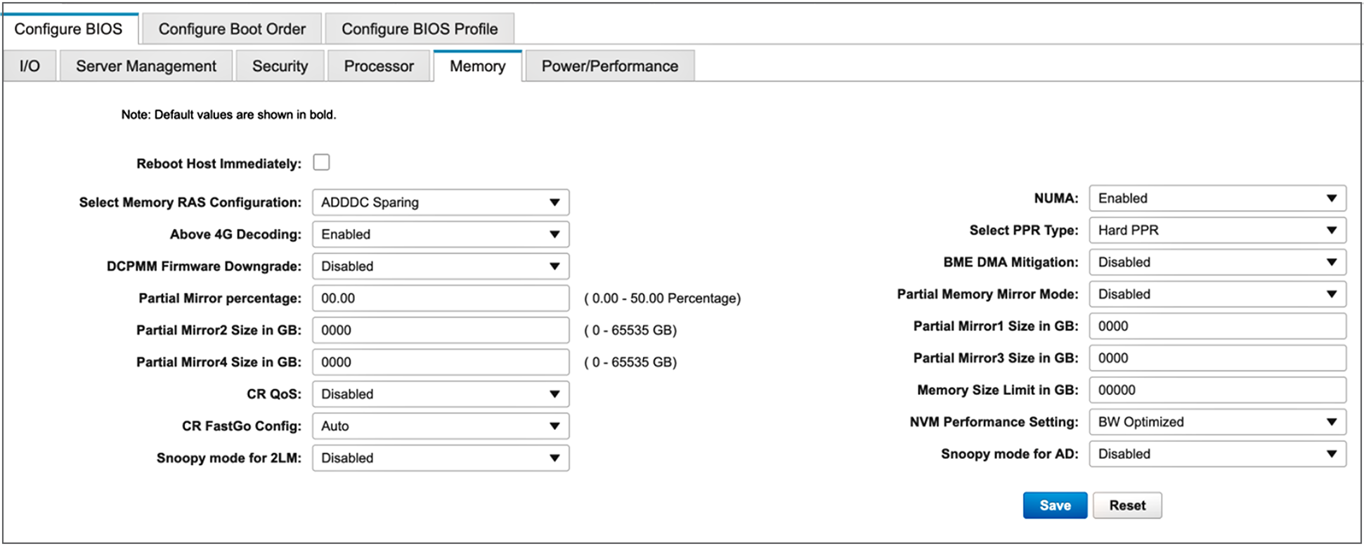
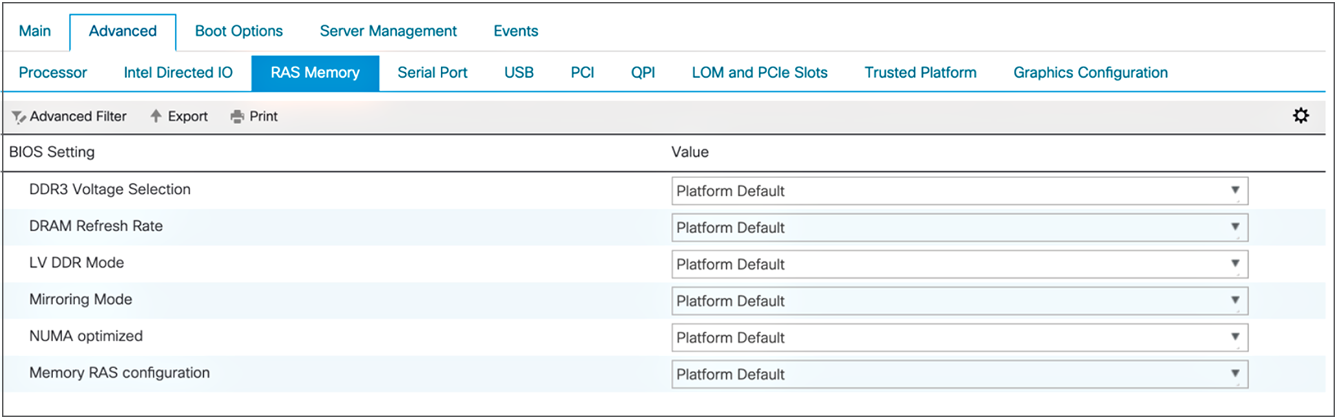
Figure 3 shows the recommended settings for optimizing memory for OLTP workloads on servers managed by Cisco UCS Manager.

Memory settings for OLTP workloads
Processor and memory settings for standalone Cisco UCS C-Series servers: OLTP
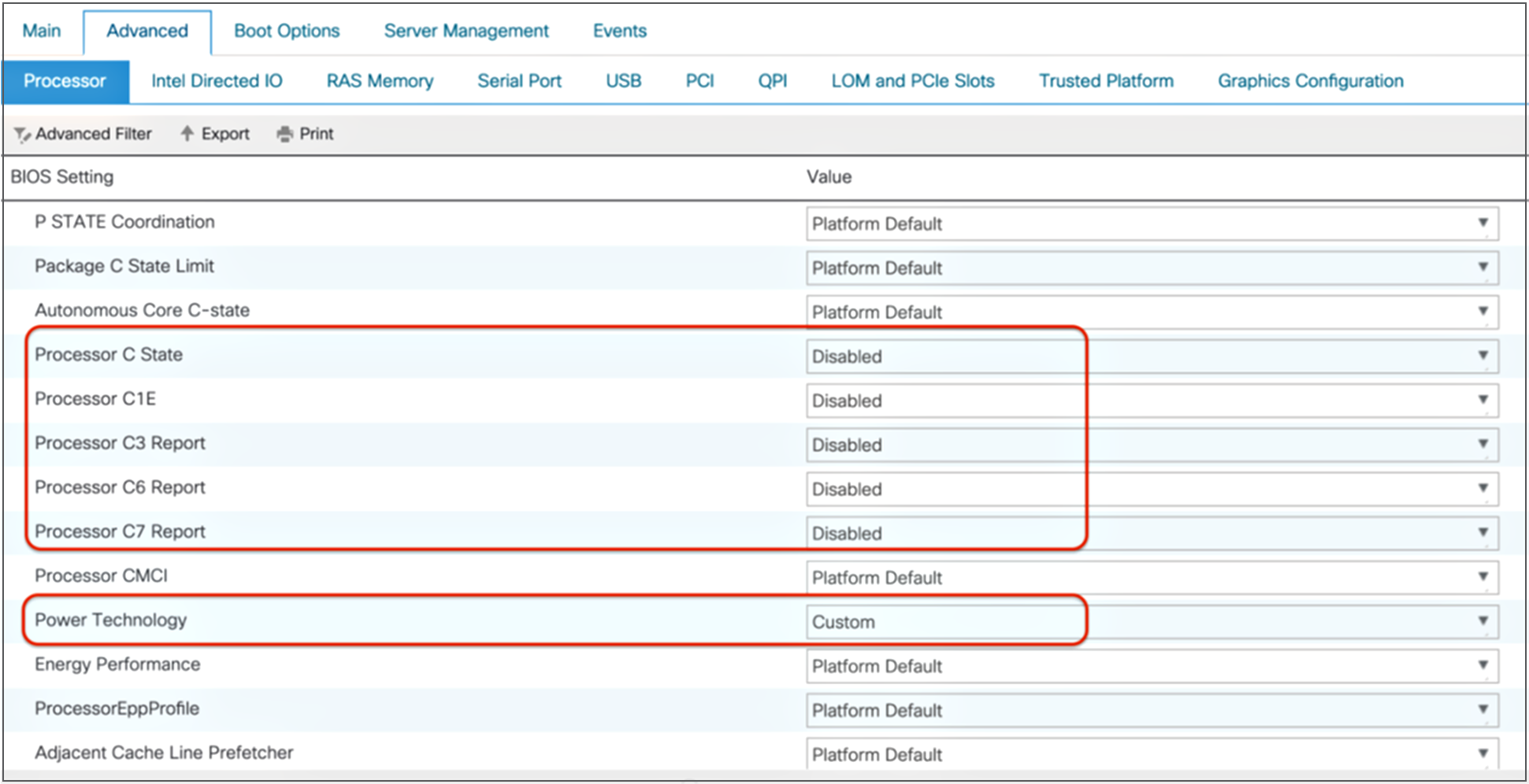
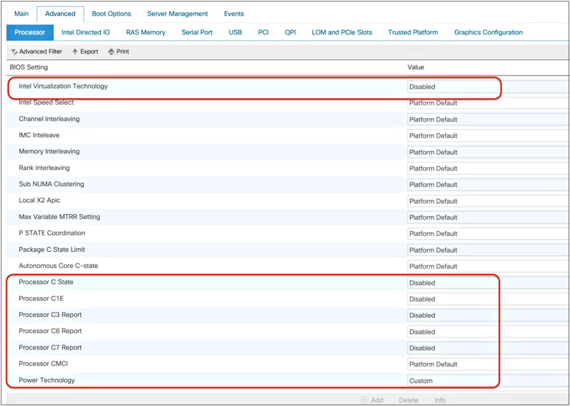
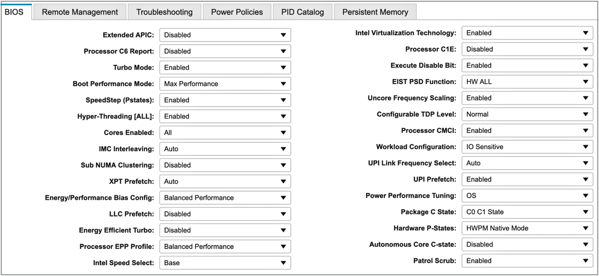
Figures 4 and 5 show the processor selections that are recommended for OLTP workloads on standalone Cisco UCS C-Series M5 servers.
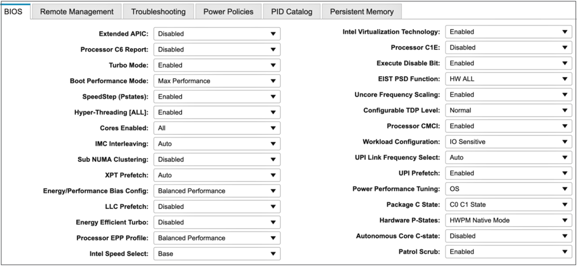
Processor settings for OLTP workloads

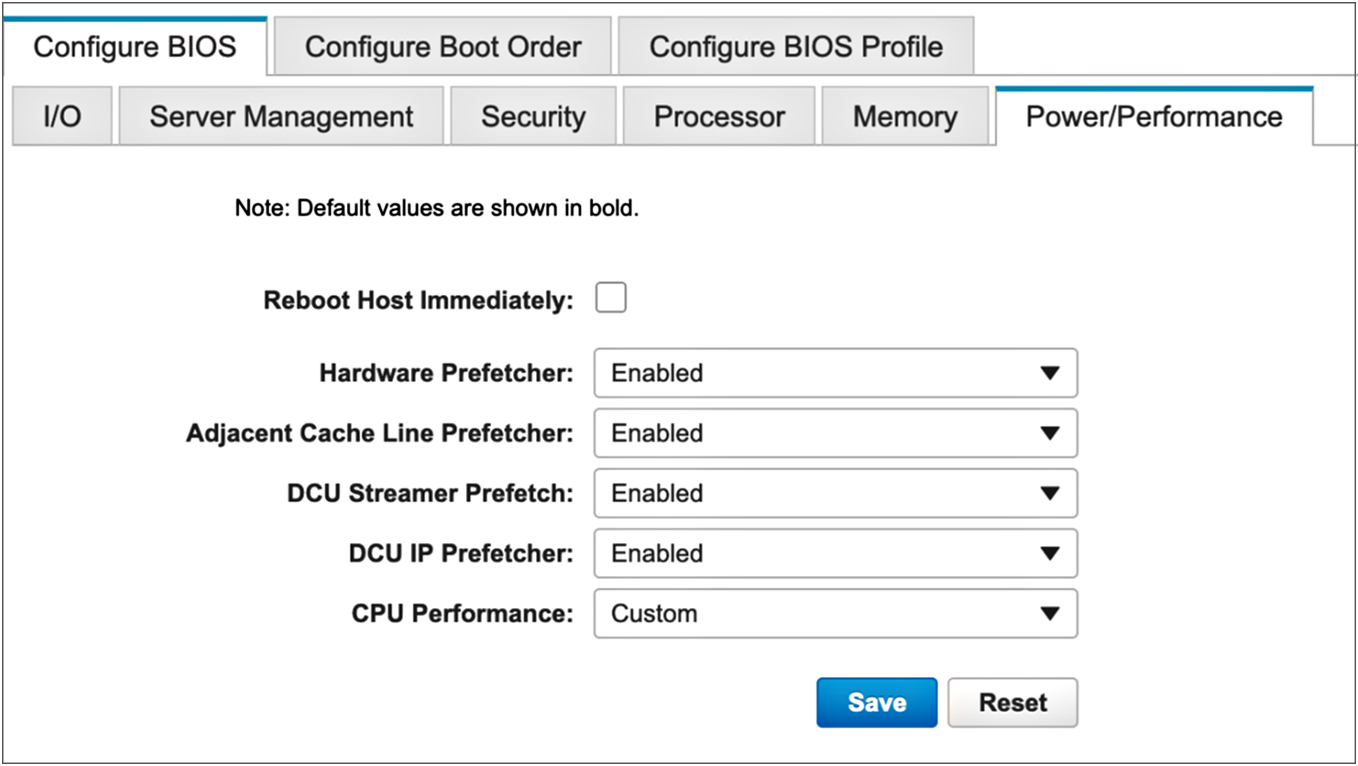
Power and performance settings for OLTP workloads
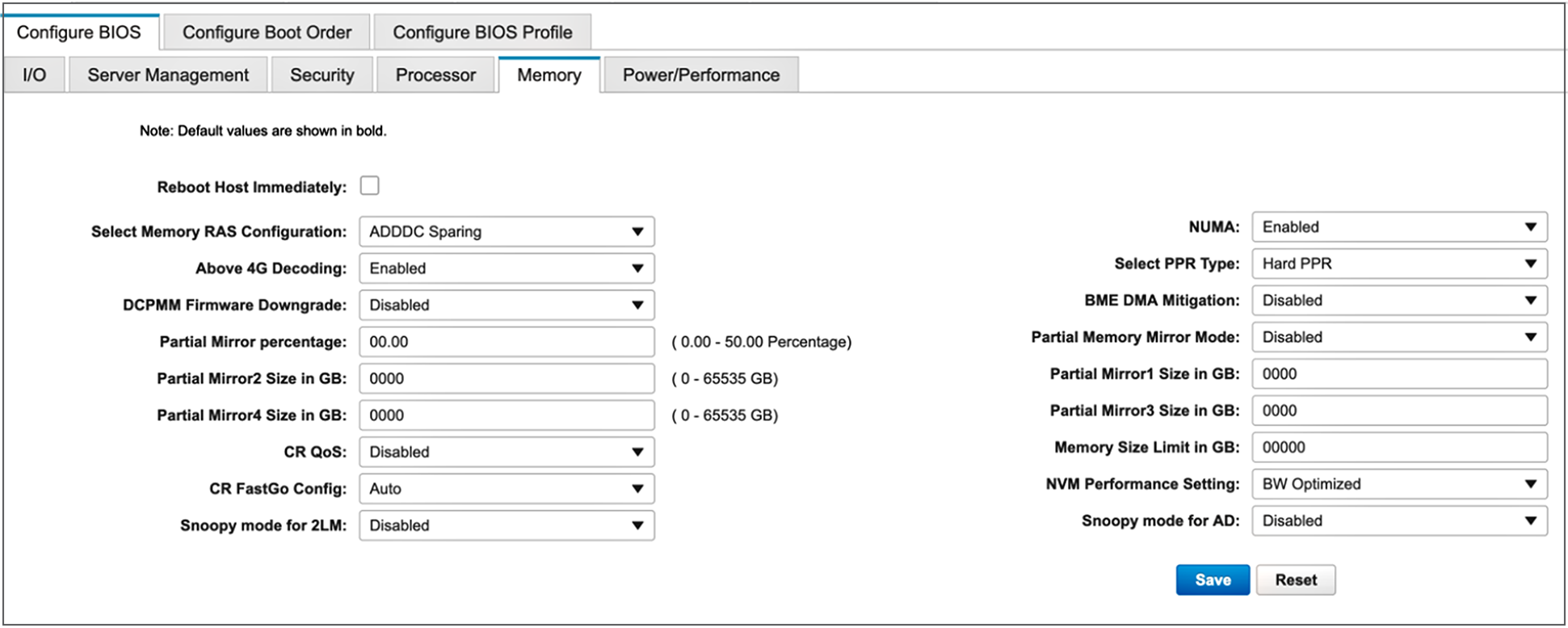
Figure 6 shows memory settings for OLTP workloads for standalone Cisco UCS C-Series servers.

Memory settings for OLTP workloads
OLTP applications have a random memory-access pattern and benefit greatly from larger and faster memory. Therefore, Cisco recommends setting memory RAS features to maximum performance for optimal system performance. In OLTP transactions, if these modes are enabled, I/O operations will be serviced at the highest frequency and will have reduced memory latency.
Note: If the DIMM pairs in the server have the same type, size, and organization and are populated across the Scalable Memory Interconnect (SMI) channels, you can enable the lockstep mode, an option on the Select Memory RAS menu, to reduce memory-access latency and achieve better performance.
Intel Virtualization Technology provides manageability, security, and flexibility in IT environments that use software-based virtualization solutions. With this technology, a single server can be partitioned and can be projected as several independent servers, allowing the server to run different applications on the operating system simultaneously.
Processor and memory settings for Cisco UCS managed servers: Virtualization
Figure 7 Highlights the BIOS selections that are recommended for virtualized workloads on Cisco UCS M5 platforms managed by Cisco UCS manager. Rest of the BIOS settings are configured as “Platform Default”.
Processor settings for virtualized workloads
Most of the CPU and memory settings for virtualized workloads are the same as those for OLTP workloads. It is important to enable Intel Virtualization Technology in the BIOS to support virtualization workloads. Make sure that the Intel VT-d option is enabled.
The CPUs that support hardware virtualization allow the processor to run multiple operating systems in the virtual machines. This feature involves some overhead because the performance of a virtual operating system is comparatively slower than that of the native OS. To enhance performance, be sure to enable Intel Turbo Boost and Hyper-Threading for the processors.
The cache prefetching mechanisms (Data-Prefetch-Logic [DPL] prefetch, hardware prefetch, Layer 2 streaming prefetch, and adjacent-cache-line prefetch) usually help increase system performance, especially when memory-access patterns are regular.
Intel Directed I/O for virtualized workloads
Figure 8 shows the recommended Intel Directed I/O settings for virtualized workloads in Cisco UCS M5 platforms.
Intel Directed I/O settings for virtualized workloads
With Cisco Data Center Virtual Machine Fabric Extender VM-FEX technology, virtual machines can now directly write to the virtual network interface cards (vNICs) when the Intel Directed I/O option is enabled at the BIOS level.
Memory settings for virtualized workloads
Figure 9 shows the recommended memory settings for virtualized workloads in Cisco UCS M5 servers.

Memory settings for virtualized workloads
When running applications that access memory randomly, set the Select Memory RAS option to Maximum Performance. This setting helps achieve optimal system performance. In virtualized environments, run the memory at the highest frequency to reduce memory latency.
Processor and memory settings for standalone Cisco UCS C-Series servers: Virtualization
Figures 10 and 11 show processor and power and performance settings for virtualized workloads in standalone Cisco UCS C-Series M5 servers.
Processor settings for virtualized workloads

Power and performance settings for virtualized workloads
Memory settings for virtualized workloads
Figure 12 shows memory settings for virtualized workloads in standalone Cisco UCS C-Series M5 servers.

Memory settings for virtualized workloads
High-performance computing workloads
HPC refers to cluster-based computing that uses multiple individual nodes that are connected and that work in parallel to reduce the amount of time required to process large data sets that would otherwise take exponentially longer to run on any one system. HPC workloads are computation intensive and typically also network-I/O intensive. HPC workloads require high-quality CPU components and high-speed, low-latency network fabrics for their Message Passing Interface (MPI) connections.
Computing clusters include a head node that provides a single point for administering, deploying, monitoring, and managing the cluster. Clusters also have an internal workload management component, known as the scheduler, that manages all incoming work items (referred to as jobs). Typically, HPC workloads require large numbers of nodes with nonblocking MPI networks so that they can scale. Scalability of nodes is the single most important factor in determining the achieved usable performance of a cluster.
Processor and memory settings for Cisco UCS managed servers: HPC
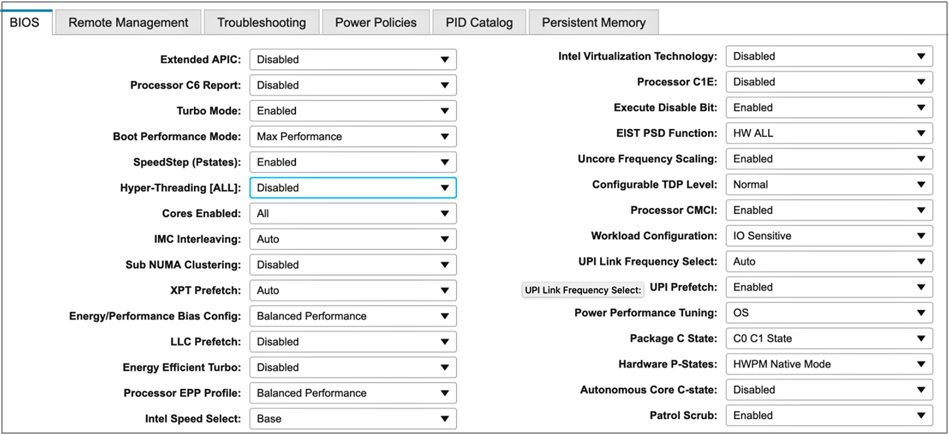
Figure 13 Highlights the BIOS selections that are recommended for HPC workloads on Cisco UCS M5 platforms managed by Cisco UCS Manager. Rest of the BIOS settings are configured as “Platform Default”.
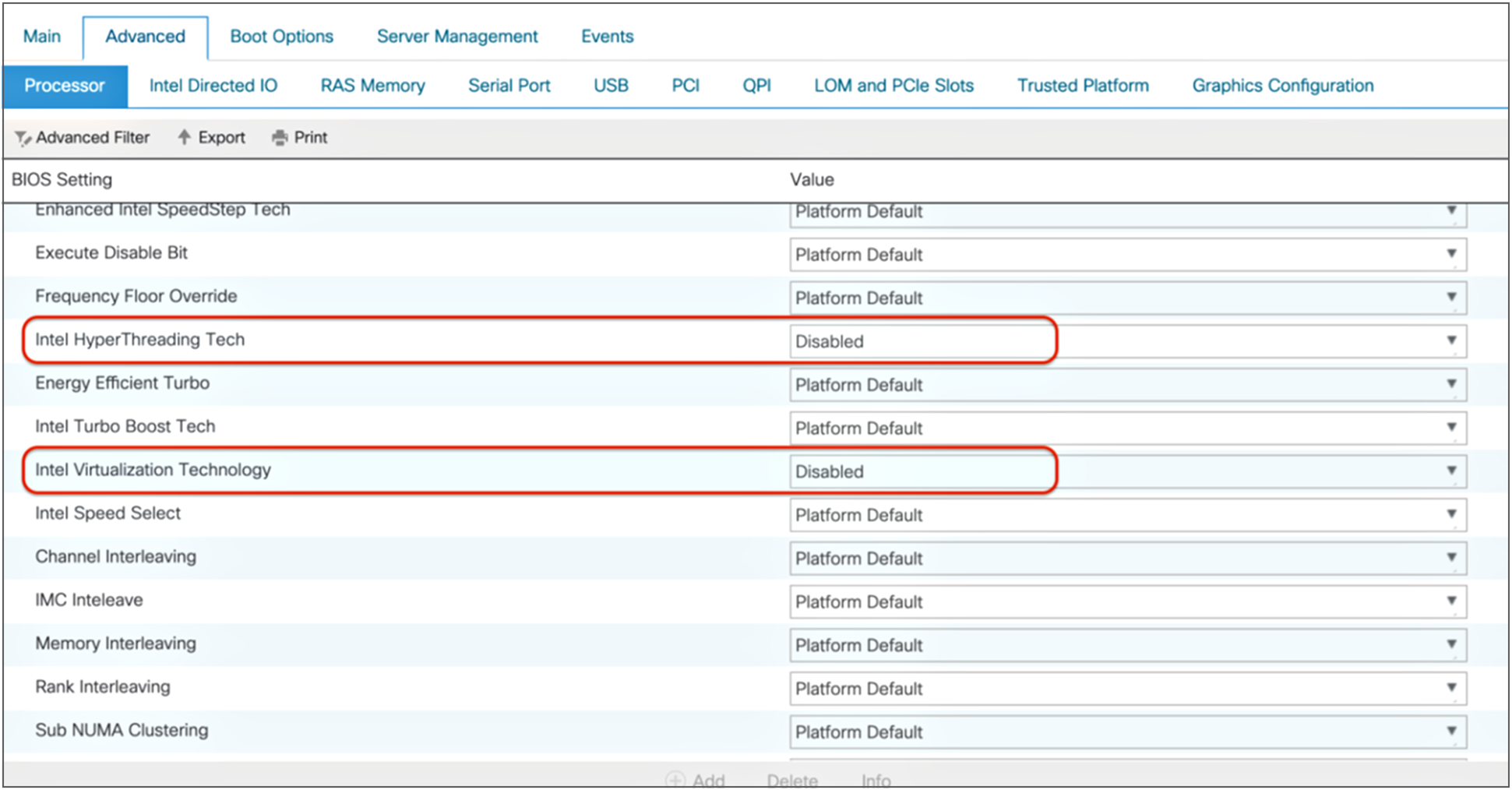
Processor settings for HPC workloads
You should enable Intel Turbo Boost technology for HPC workloads to increase the computing power. When Intel Turbo Boost is enabled, each core provides higher computing frequency potential, allowing a greater number of parallel requests to be processed efficiently.
Intel SpeedStep is enabled because it is required for Intel Turbo Boost to function.
HPC workloads typically do not benefit from Intel Hyper-Threading. Additional threads only serve to create resource contention within the microarchitecture of the CPU. Generally, Intel Hyper-Threading has the greatest impact on workloads in which threads are forced to wait for completion of back-end I/O requests, to reduce thread contention for CPU resources.
Enabling the processor power state C6 helps save power when the CPU is idle. Because HPC is computing intensive, the CPU will likely seldom go into an idle state. However, enabling C-states saves CPU power in the event that there are any inactive requests.
You should set CPU Performance to HPC mode to handle more random, parallel requests by HPC applications. If HPC performs more in-memory processing (for example, for video data), you should enable the prefetcher options so that they can handle multiple parallel requests. This configuration also helps retain some hot data in the Layer 2 cache, and it improves HPC performance (CPU performance).
HPC requires a high-bandwidth I/O network. When you enable DCA support, network packets go directly into the Layer 3 processor cache instead of the main memory. This approach reduces the number of HPC I/O cycles generated by HPC workloads when certain Ethernet adapters are used, which in turn increases system performance.
You can set the Energy Performance option to Maximum Performance, Balanced Performance, Balanced Power, or Power Saver. Test results demonstrate that most applications run best with the Balanced Performance setting. Applications that are highly I/O sensitive perform best when the Energy Performance option is set to Maximum Performance.
Intel Directed I/O for HPC workloads
Figure 14 shows the recommended Intel Directed I/O settings for HPC workloads in Cisco UCS M5 platforms.
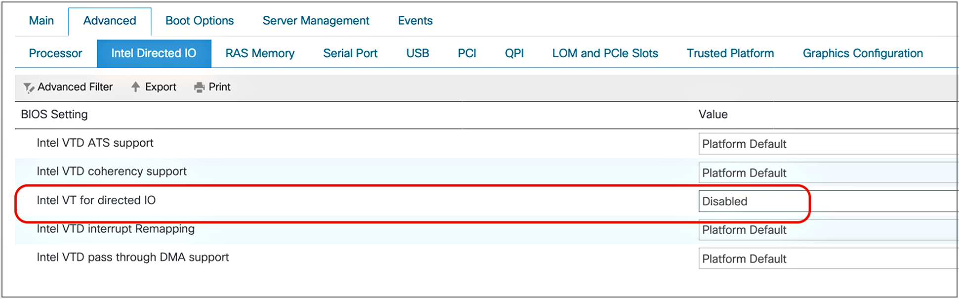
Intel Directed I/O settings for HPC workloads
Memory settings for HPC workloads
Figure 15 shows the memory settings for HPC workloads on Cisco UCS M5 servers.
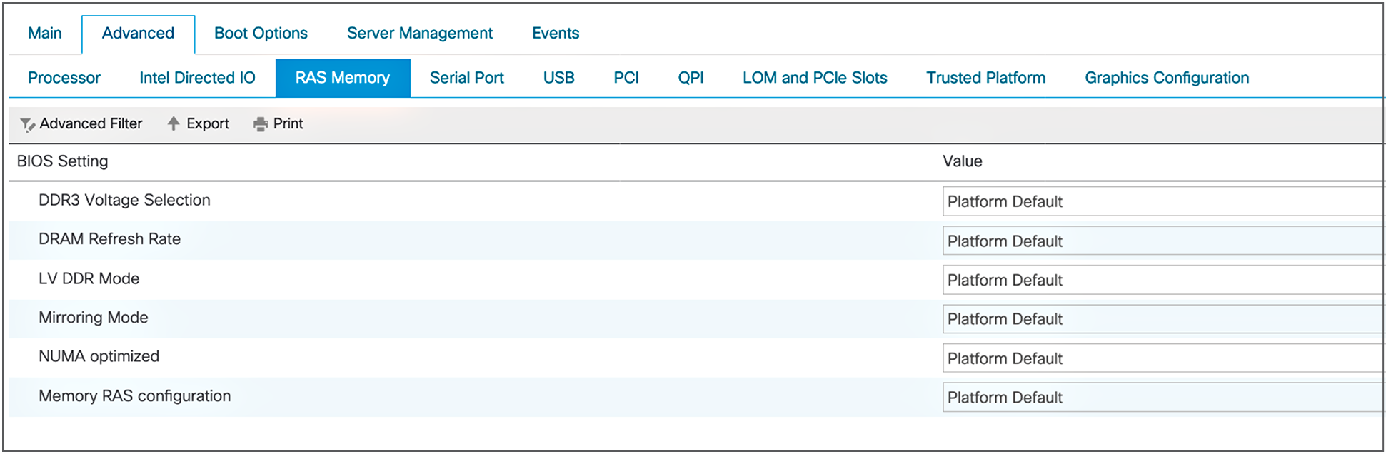
Memory settings for HPC workloads
The NUMA option should be enabled for HPC workloads so that NUMA can determine the memory allocation for each thread run by the HPC applications.
Because HPC workloads perform mostly in-memory processing, you should set DIMMs to run at the highest available frequency to process the data more quickly.
Processor and memory settings for standalone Cisco UCS C-Series servers: HPC
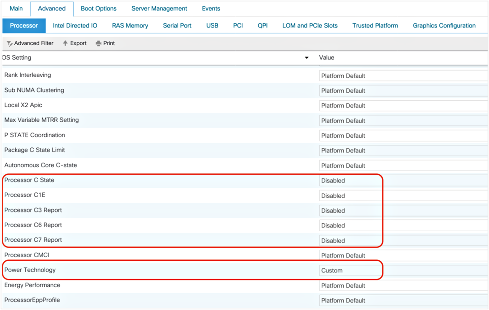
Figures 16 and 17 show the recommended processor and power and performance settings for HPC workloads in standalone Cisco UCS C-Series M5 servers.
Processor settings for HPC workloads

Power and performance settings for HPC workloads
Figures 18 shows memory settings for HPC workloads for standalone Cisco UCS C-Series M5 servers.
Memory settings for HPC workloads
Java Enterprise Edition application server workloads
Java EE (previously referred to as the J2EE) defines the core set of APIs and features of Java application servers. Usually, Java EE applications are client-server or server-side applications and require a Java EE application server.
Java EE application servers are distinguished by the following characteristics:
● They are fully compliant application servers that implement the full Java EE stack specifications with features such as JBoss Enterprise. Examples of fully compliant application servers are Apache Geronimo and JBoss Application Server.
● They are web application servers that support only the web tier of Java EE, including the servlet. Examples of fully compliant application servers are Apache Tomcat and Jetty.
Processor and memory settings for Cisco UCS managed servers: Java EE
Figure 19 Highlights the BIOS selections that are recommended for Java EE application servers on Cisco UCS M5 servers managed by Cisco UCS Manager. Rest of the BIOS settings are configured as “Platform Default”.
Processor settings for Java EE application workloads
Intel Turbo Boost Technology enables higher CPU frequency, which helps accelerate processing of application requests. This feature helps reduce end-user response time.
Business scenarios such as batch processes run at a certain time of the day benefit from Intel Turbo Boost. It enables CPU cores to achieve at higher frequency clock speeds, which helps lower batch processing time, thereby helping the business complete and generate business reports more quickly.
You should enable all the C-states. This configuration helps reduce power consumption because only active cores will process requests during nonpeak hours. If the application demands more CPU cores, the inactive cores will become active, which helps increase throughput.
The CPU Performance option should be set to Enterprise. When a web server needs to process a large amount of data in a system, the data-access pattern is predictable (mostly sequential or adjacent lines are accessed). In this situation, it is desirable to enable the prefetchers (MLC and DCU) by setting CPU Performance to Enterprise, to reduce access latency for memory-bound operations.
Intel Directed I/O for Java application workloads
Figure 20 shows the recommended Intel Directed I/O settings for Java application workloads in Cisco UCS M5 servers.
Intel Directed I/O settings for Java application workloads
Memory settings for Java EE application server workloads
Figure 21 shows the recommended memory settings for Java EE application servers for Cisco UCS M5 servers managed by Cisco UCS Manager.

Memory settings for Java EE application workloads
Set the DDR mode to Performance so that the DIMMs work at the highest available frequency for the installed memory and CPU combination. In-memory enterprise applications such as Terracotta Ehcache benefit from the high memory speed. If this mode is enabled in web server workloads, I/O operations will be serviced at the highest frequency, and memory latency will be reduced.
Processor and memory settings for standalone Cisco UCS C-Series servers: Java EE
Figures 22 and 23 show processor and performance and power settings for Java EE applications in standalone Cisco UCS C-Series M5 servers.
Processor settings for Java EE application workloads
Power and performance settings for Java EE application workloads
Figure 24 shows memory settings for Java EE applications for standalone Cisco UCS C-Series M5 servers.
Memory settings for Java EE application workloads
Analytics database decision-support system workloads
An analytics database is a read-only system that stores historical data for business metrics such as sales performance and inventory levels.
An analytics database is specifically designed to support Business Intelligence (BI) and analytics applications, typically as part of a data warehouse or data mart. This feature differentiates it from operational, transactional, and OLTP databases, which are used for transaction processing: order entry and other “run the business” applications.
Processor and memory settings for Cisco UCS managed servers: DSS
Figure 25 Highlights the BIOS selections that are recommended for analytics database systems on Cisco UCS M5 servers managed by Cisco UCS Manager. Rest of the BIOS settings are configured as “Platform Default”.
Processor settings for analytics database DSS workloads
Intel Directed I/O for analytics database DSS workloads
Figure 26 shows the recommended Intel Directed I/O settings for analytics database DSS workloads on Cisco UCS M5 servers managed by Cisco UCS Manager.
Intel Directed I/O settings for analytics database DSS workloads
Memory settings for analytics database DSS workloads
Figure 27 show the recommended memory settings for analytics database DSS workloads on Cisco UCS M5 servers managed by Cisco UCS Manager.
Memory settings for analytics database DSS workloads
Processor and memory settings for standalone Cisco UCS C-Series servers: DSS
Figures 28 and 29 show processor and performance and power settings for analytics database DSS workloads on standalone Cisco UCS C-Series M5 servers.
Processor settings for analytics database DSS workloads

Power and performance settings for analytics database DSS workloads
Figure 30 shows memory settings for analytics database DSS workloads in standalone Cisco UCS C-Series M5 servers.
Memory settings for analytics database DSS workloads
When tuning system BIOS settings for performance, you need to consider a number of processor and memory options. If the best performance is your goal, be sure to choose options that optimize for performance in preference to power savings, and experiment with other options such as CPU prefetchers, CPU power management, and CPU hyperthreading.
For more information about Cisco UCS B-Series and C-Series M5 servers, see:
● Cisco UCS B200 M5 Blade Server: https://www.cisco.com/c/dam/en/us/products/collateral/servers-unified-computing/ucs-b-series-blade-servers/b200m5-specsheet.pdf
● Cisco UCS C220 M5 Rack Server: https://www.cisco.com/c/dam/en/us/products/collateral/servers-unified-computing/ucs-c-series-rack-servers/c220m5-sff-specsheet.pdf
● Cisco UCS C240 M5 Rack Server: https://www.cisco.com/c/dam/en/us/products/collateral/servers-unified-computing/ucs-c-series-rack-servers/c240m5-sff-specsheet.pdf
● Cisco UCS B480 M5 Blade Server: https://www.cisco.com/c/dam/en/us/products/collateral/servers-unified-computing/ucs-b-series-blade-servers/b480m5-specsheet.pdf
● Cisco UCS C480 M5 Rack Server: https://www.cisco.com/c/dam/en/us/products/collateral/servers-unified-computing/ucs-c-series-rack-servers/c480-m5-high-performance-specsheet.pdf