Performance Tuning for Cisco UCS C225 M6 and C245 M6 Rack Servers with 3rd Gen AMD EPYC Processors White Paper
Available Languages
Bias-Free Language
The documentation set for this product strives to use bias-free language. For the purposes of this documentation set, bias-free is defined as language that does not imply discrimination based on age, disability, gender, racial identity, ethnic identity, sexual orientation, socioeconomic status, and intersectionality. Exceptions may be present in the documentation due to language that is hardcoded in the user interfaces of the product software, language used based on RFP documentation, or language that is used by a referenced third-party product. Learn more about how Cisco is using Inclusive Language.
The BIOS tests and initializes the hardware components of a system and boots the operating system from a storage device. A typical computational system has several BIOS settings that control the system’s behavior. Some of these settings are directly related to the performance of the system.
This document explains the BIOS settings that are valid for the Cisco Unified Computing System (Cisco UCS) servers with 3rd Gen AMD EPYC processors: the Cisco UCS C225 M6 and C245 M6 Rack Servers using the AMD EPYC processor. It describes how to optimize the BIOS settings to meet requirements for best performance and energy efficiency for the Cisco UCS C225 M6 and C245 M6 servers.
This document also discusses the BIOS settings that can be selected for various workload types on Cisco UCS C225 M6 and C245 M6 servers that use 3rd Gen AMD EPYC CPUs. Understanding the BIOS options will help you select appropriate values to achieve optimal system performance.
This document does not discuss the BIOS options for specific firmware releases of Cisco UCS servers. The settings demonstrated here are generic.
The process of setting performance options in your system BIOS can be daunting and confusing, and some of the options you can choose are obscure. For most options, you must choose between optimizing a server for power savings or for performance. This document provides some general guidelines and suggestions to help you achieve optimal performance from your Cisco UCS C225 M6 and C245 M6 Servers that uses 3rd Gen AMD EPYC family CPUs.
AMD EPYC 7003 Series processors
The AMD EPYC 7003 Series processors are built with innovative Zen 3 cores and AMD Infinity architecture. The AMD EPYC system-on-a-chip (SoC) offers a consistent set of features across 8 to 64 cores. Each 3rd Gen EPYC processor consists of up to 8 core Complex Dies (CCDs) and an I/O Die (IOD). Each CCD contains one Core Complex (CCX), so each CCD contains up to 8 Zen 3 cores. Using AMD Infinity Fabric, the CCDs connect to the I/O Die (IOD) to access memory, I/O, and each other. Up to 8 memory channels, 4 TB of high-speed memory per socket, and 128 lanes of PCIe Gen 4 are supported.
In 2-socket systems, two EPYC 7003 Series SoCs are connected through their corresponding Infinity Fabric, or External Global Memory interconnect (xGMI), links. This design creates a high-bandwidth, low-latency interconnect between the two processors.
AMD EPYC 7003 Series processors are built with the specifications listed is listed below.
Table 1. AMD EPYC 7003 Series specifications
|
|
|
| Cores process technology |
7 nanometer (nm) |
| Maximum number of cores |
64 |
| Maximum memory speed |
3200 mega-transfers per second (MT/s) |
| Maximum memory channels |
8 per socket |
| Maximum memory capacity |
4 TB per socket |
| PCI |
128 lanes (maximum) PCIe Gen 4 |
For more information about the AMD EPYC 7003 Series processors microarchitecture, see Overview of AMD EPYC 7003 Series Processors Microarchitecture.
Non-Uniform Memory Access (NUMA) topology
The AMD EPYC 7003 Series processors use a Non-Uniform Memory Access (NUMA) memory architecture. The four logical quadrants in the IOD of an AMD EPYC 7003 Series processor, as described in the previous section, allow the processor to be partitioned into different NUMA domains.
Using system BIOS settings, users can optimize this NUMA topology for their specific operating environments and workloads with the NUMA Nodes per Socket (NPS) BIOS setting. Each server can be configured with NPS = 1 (NPS1), NPS = 2 (NPS2), NPS = 4 (NSP4), or NPS = 0 (NPS0; not recommended), with an additional option to configure the Layer 3 cache as NUMA (L3CAN). Not all AMD EPYC 7003 Series processors can be set to NPS4. Some CPUs have only six CCDs per socket, in which case only NPS1 and NPS2 are recommended.
AMD Rome and Milan 64-core CPUs can support three NUMA domains for which the BIOS can be configured as shown below:
● 1 node per socket (entire node)
● 2 nodes per socket (black dotted line)
● 4 nodes per socket (red dotted line)
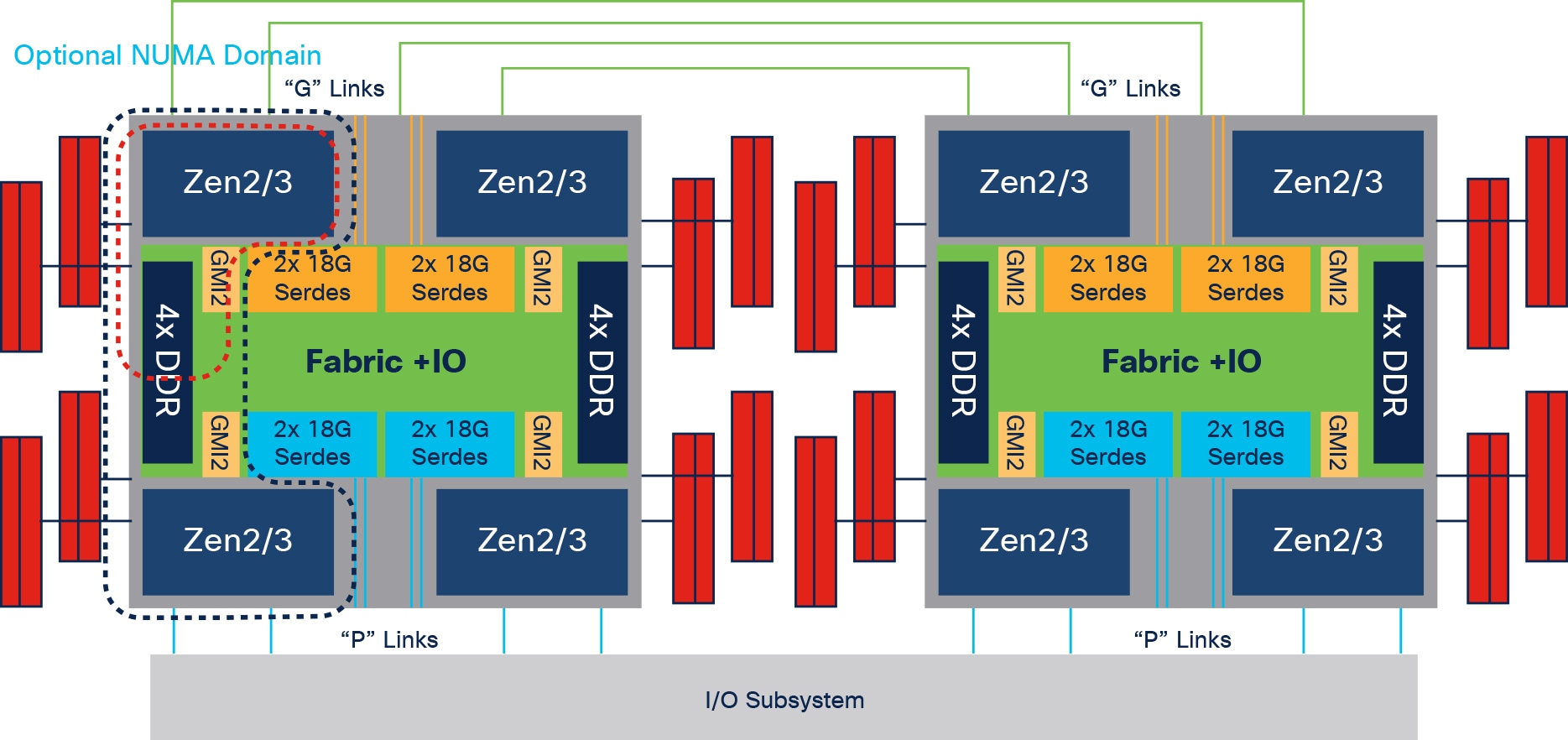
AMD Rome and Milan processor block diagram with NUMA domains
NPS1 indicates a single NUMA node per socket (or CPU). This setting configures all memory channels on the processor into a single NUMA domain: that is, all the cores on the processor, all memory connected to it, and all PCIe devices connected to the processor are in one NUMA domain. Memory is then interleaved across all eight memory channels on the processor.
In NPS2, the processor is partitioned into two NUMA domains. Half the cores and half the memory channels of each processor are grouped together into one NUMA domain, and the remaining cores and memory channels are grouped into a second domain. Memory is interleaved across the four memory channels in each NUMA domain.
NPS4 partitions the processor into four NUMA domains. Each logical quadrant of the processor is configured as its own NUMA domain. Memory is interleaved across the two memory channels in each quadrant. PCIe devices will be local to one of the four NUMA domains on the processor depending on the quadrant of the IOD that has the PCIe root for that device.
NPS0 (not recommended)
NPS0 interleaves memory access all memory channels on a two-socket system. This configuration should generally be avoided, because it adds intersocket latency to every memory access.
In addition to the NPS settings, one more BIOS option for changing NUMA configurations is available. With the Layer 3 Cache as NUMA (L3CAN) option, each Layer 3 cache (one per CCD) is exposed as its own NUMA node. For example, a single processor with eight CCDs would have 8 NUMA nodes: one for each CCD. In this case, a two-socket system would have a total of 16 NUMA nodes.
Tuning for general-purpose workloads
With the latest multiprocessor, multicore, and multithreading technologies in conjunction with current operating systems and applications, today's Cisco UCS servers based on the 3rd Gen AMD EPYC processor deliver the highest levels of performance, as demonstrated by the numerous industry-standard benchmark publications from the Standard Performance Evaluation Corporation (SPEC).
Cisco UCS servers with standard settings already provide an optimal ratio of performance to energy efficiency. However, through BIOS settings you can further optimize the system with higher performance and less energy efficiency. Basically, this optimization operates all the components in the system at the maximum speed possible and prevents the energy-saving options from slowing down the system. In general, optimization to achieve greater performance is in most cases associated with increased consumption of electrical power. This document explains how to configure the BIOS settings to achieve optimal computing performance.
Tuning for enterprise workloads
Performance tuning is difficult and general recommendations are problematic. This document tries to provide insights into optimal BIOS settings and OS tunings that have an impact on overall system performance. This document does not provide generic rule-of-thumb values to be used for performance tuning. The finest tuning of the parameters described requires a thorough understanding of the enterprise workloads and the Cisco UCS platform on which they run.
This section describes the options you can configure in the Cisco UCS BIOS.
You can configure the processor and BIOS settings through the Cisco Integrated Management Controller (IMC), Cisco UCS Manager and Cisco Intersight platform for a standalone system and Cisco Intersight Managed Mode systems. The BIOS settings for memory, processor, and power are on the Memory, Power/Performance, and Processor tabs. The BIOS tokens specific to AMD servers in Cisco Intersight Managed Mode is highlighted in red. Figure 2, Figure 3, and Figure 4 show the BIOS settings available using the IMC, Figure 5, Figure 6, Figure 7, Figure 8, and Figure 9 show the BIOS settings available using the Cisco Intersight platform and Figure 10 shows the BIOS settings available through Cisco UCS Manager for 3rd Gen AMD EPYC processors.
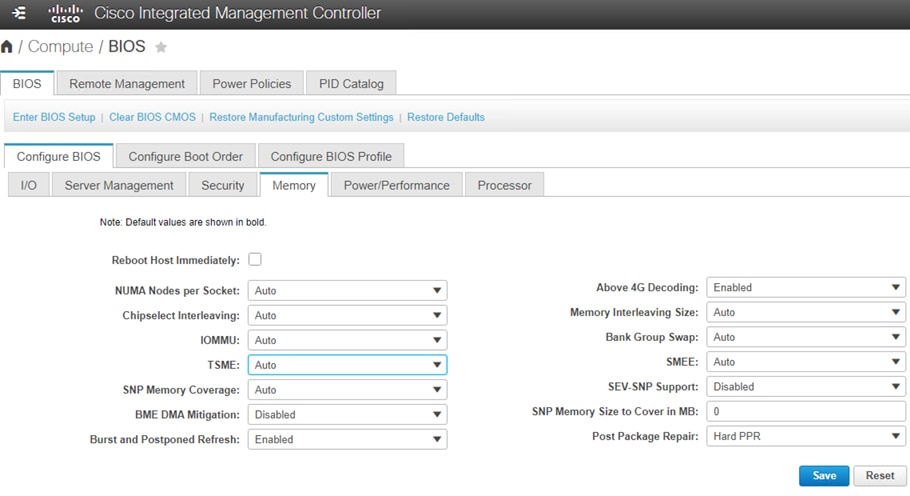
BIOS tokens for Memory available for configuration through Cisco IMC (screen 1)
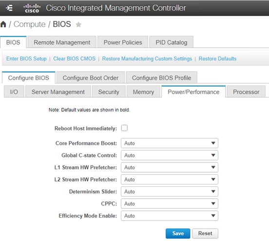
BIOS tokens for Power and Performance available for configuration through Cisco IMC (screen 2)
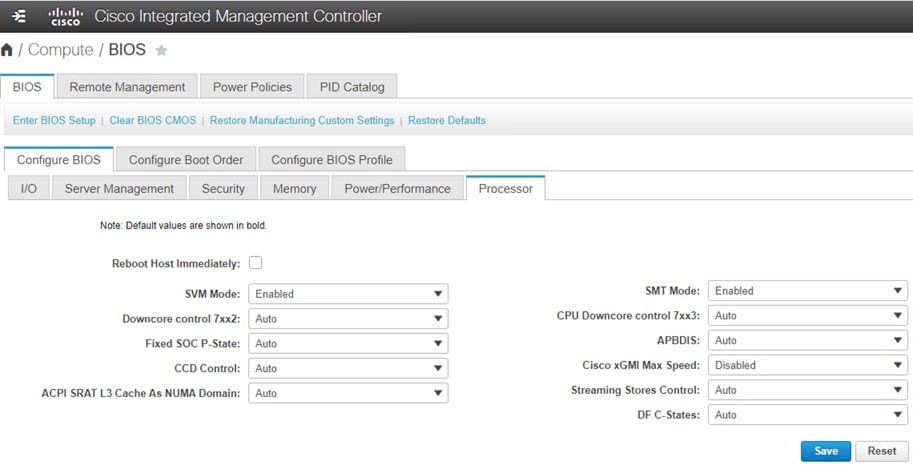
BIOS tokens for Processor available for configuration through Cisco IMC (screen 3)
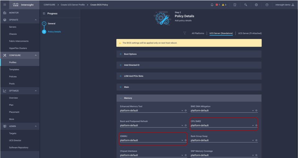
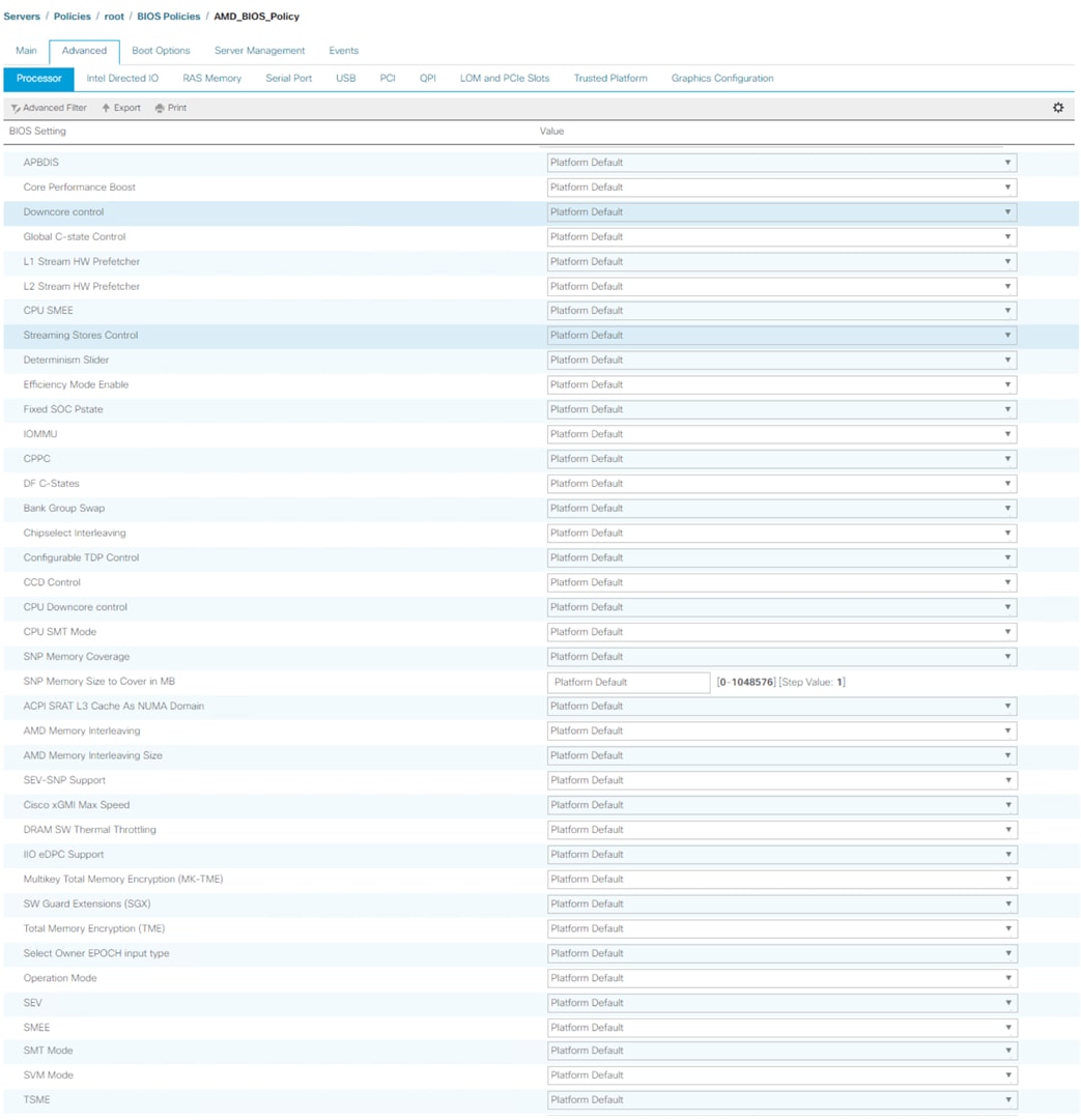
BIOS tokens for 3rd Gen AMD EPYC processor available for configuration through Cisco Intersight platform
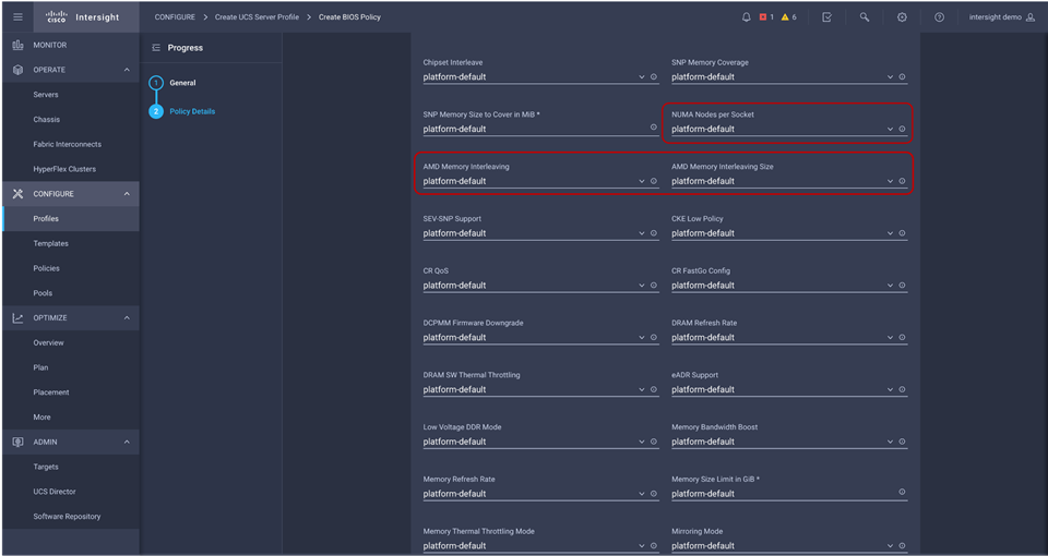
BIOS tokens for 3rd Gen AMD EPYC processor available for configuration through Cisco Intersight platform
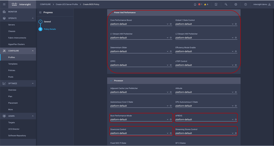
BIOS tokens for 3rd Gen AMD EPYC processor available for configuration through Cisco Intersight platform

BIOS tokens for 3rd Gen AMD EPYC processor available for configuration through Cisco Intersight platform
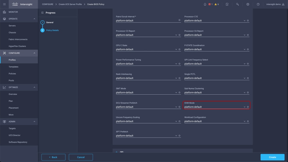
BIOS tokens for 3rd Gen AMD EPYC processor available for configuration through Cisco Intersight platform
IOS tokens for Processor available for configuration through Cisco UCS Manager
Note: The “platform default” settings in the Intersight BIOS policy is equivalent to “Auto” settings in the F2 BIOS/Cisco IMC.
Processor settings
This section describes the processor options you can configure.
You can configure the Infinity Fabric settings described in this section.
xGMI settings: Connection between sockets
In a two-socket system, the processors are interconnected through socket-to-socket xGMI links, part of the Infinity Fabric that connects all the components of the SoC together.
NUMA-unaware workloads may need maximum xGMI bandwidth because of extensive cross-socket communication. NUMA-aware workloads may want to minimize xGMI power because they do not have a lot of cross-socket traffic and prefer to use the increased CPU boost. The xGMI lane width can be reduced from x16 to x8 or x2, or an xGMI link can be disabled if power consumption is too high.
xGMI link configuration and 4-link xGMI max speed (Cisco xGMI max Speed)
You can set the number of xGMI links and maximum speed for the xGMI link. Setting this value to a lower speed can save uncore power that can be used to increase core frequency or reduce overall power. It also decreases cross-socket bandwidth and increases cross-socket latency. The Cisco UCS C245 M6 server supports four xGMI links with a maximum speed of 18 Gbps, and the Cisco UCS C225 M6 server supports three xGMI links with a maximum speed of 16 Gbps.
Cisco xGMI max Speed settings allow to configure xGMI Link configuration and 4-Link/3-Link xGMI Max Speed. Enabling Cisco xGMI max speed will set xGMI Link Configuration to 4 (3 – in case of Cisco UCS C225 M6 server), 4-Link xGMI Max Speed to 18 Gbps and incase of Cisco UCS C225 M6 server, 3-Link xGMI Max Speed will be set to 16 Gbps. Disabling Cisco xGMI Max Speed settings will apply the default values.
Cisco UCS C245 M5 and C225 M6 xGMI configuration
● Cisco UCS C245 M6 server supports up to 4 xGMI links with max speed up to 18 Gbps
● Cisco UCS C225 M6 server supports up to 3 xGMI links with max speed up to 16 Gbps
● xGMI link configuration is applicable for 2 socket system only.
Table 2 summarizes the settings.
Table 2. xGMI link settings
| Setting |
Options |
| Cisco xGMI Max Speed |
● Disabled (default)
● Enabled
|
| xGMI Link Configuration |
● Auto
● 1
● 2
● 3
● 4
|
| 4-Link xGMI Max Speed |
● Auto (13 Gbps)
● 10.667 Gbps
● 13 Gbps
● 16 Gbps
● 18 Gbps
|
| 3-Link xGMI Max Speed |
● Auto (13 Gbps)
● 10.667 Gbps
● 13 Gbps
● 16 Gbps
|
xGMI Dynamic Link Width Management (DLWM) saves power during periods of low socket-to-socket data traffic by reducing the number of active xGMI lanes per link from 16 to 8. However, under certain scenarios involving low bandwidth but latency-sensitive traffic, the transition from a low-power xGMI state to a full-power xGMI state can adversely affect latency. Setting xGMI Link Width Control to manual and specifying a Force Link Width value eliminate any such latency jitter. Applications that are known to be insensitive to both socket-to-socket bandwidth and latency can set a forced link width of 8 (or 2 on certain platforms) to save power, which can divert more power to the cores for CPU boost.
The DLWM feature is optimized to trade power between CPU core-intensive workloads (SPEC CPU) and I/O bandwidth-intensive workloads (kernel IP forward or iPerf). When link activity is above a threshold, DLWM will increase lane width from x8 to x16 at the cost of some delay, because the I/O die must disconnect the links, retrain them at the new speed, and release the system back to functionality. Table 3 summarizes the settings.
Table 3. DLWM settings
| Setting |
Options |
| DLWM |
● Auto: This setting is enabled when two CPUs are installed.
● Disable: The xGMI link width is fixed.
|
You can configure the power state settings described in this section.
Algorithm Performance Boost (APBDIS) and SoC P-states
Enable or disable Algorithm Performance Boost (APB). In the default state, the Infinity Fabric selects between a full-power and low-power fabric clock and memory clock based on fabric and memory use. However, in certain scenarios involving low bandwidth but latency-sensitive traffic (and memory latency checkers), the transition from low power to full power can adversely affect latency. Setting APBDIS to 1 (to disable APB) and specifying a fixed Infinity Fabric P-state of 0 will force the Infinity Fabric and memory controllers into full-power mode, eliminating any such latency jitter. Certain CPU processors and memory population options result in a scenario in which setting a fixed Infinity Fabric P- state of 1 will reduce memory latency at the expense of memory bandwidth. This setting may benefit applications known to be sensitive to memory latency. Table 4 summarizes the settings.
Table 4. APBDIS and SoC P-state settings
| Setting |
Options |
| APBDIS |
● Auto (0)
● 0: Dynamically switch Infinity Fabric P-state based on link use.
● 1: Enable fixed Infinity Fabric P-state control.
|
| Fixed SOC P-State |
● Auto
● P0: Highest-performing Infinity Fabric P-state
● P1: Next-highest-performing Infinity Fabric P-state
● P2: Next highest-performing Infinity Fabric P-state
● P3: Lowest Infinity Fabric power P-state
|
Much like CPU cores, the Infinity Fabric can go into lower power states while idle. However, there will be a delay to change back to full-power mode causing some latency jitter. In a low-latency workload or one with bursty I/O, you can disable the Data Fabric (DF) C-states feature to achieve more performance with the trade-off of higher power consumption. Table 5 summarizes the settings.
Table 5. Data fabric C-state settings
| Setting |
Options |
| DF C-States |
● Disabled: Do not allow Infinity Fabric to go to a low-power state when the processor has entered Cx states.
● Enabled (Auto): Allow Infinity Fabric to go to a low-power state when the processor has entered Cx states.
|
You can configure the NUMA and memory settings described in this section.
This setting lets you specify the number of desired NUMA nodes per socket (NPS) and enables a trade-off between reducing local memory latency for NUMA-aware or highly parallelizable workloads and increasing per-core memory bandwidth for non-NUMA-friendly workloads. Socket interleave (NPS0) will attempt to interleave the two sockets together into one NUMA node. 3rd Gen AMD EPYC processors support a varying number of NUMA NPS values depending on the internal NUMA topology of the processor. NPS2 and NPS4 may not be options on certain processors or with certain memory populations.
In one-socket servers, the number of NUMA nodes per socket can be 1, 2, or 4, though not all values are supported by every processor. Performance for applications that are highly NUMA optimized can be improved by setting the number of NUMA nodes per socket to a supported value greater than 1.
The default configuration (one NUMA domain per socket) is recommended for most workloads. NPS4 is recommended for high-performance computing (HPC) and other highly parallel workloads. When using 200-Gbps network adapters, NPS2 may be preferred to provide a compromise between memory latency and memory bandwidth for the network interface card (NIC). This setting is independent of the Advanced Configuration and Power Interface (ACPI) Static Resource Affinity Table (SRAT) Layer 3 (L3) Cache as NUMA Domain setting. When ACPI SRAT L3 Cache as NUMA Domain is enabled, this setting then determines the memory interleaving granularity. With NPS1, all eight memory channels are interleaved. With NPS2, every four channels are interleaved with each other. With NPS4, every pair of channels is interleaved. Table 6 summarizes the settings.
Table 6. NUMA NPS settings
| Setting |
Options |
| NUMA Nodes per Socket |
● Auto (NPS1)
● NPS0: Interleave memory accesses across all channels in both sockets (not recommended).
● NPS1: Interleave memory accesses across all eight channels in each socket; report one NUMA node per socket (unless L3 Cache as NUMA is enabled).
● NPS2: Interleave memory accesses across groups of four channels (ABCD and EFGH) in each socket; report two NUMA nodes per socket (unless L3 Cache as NUMA is enabled).
● NPS4: Interleave memory accesses across pairs of two channels (AB, CD, EF, and GH) in each socket; report four NUMA nodes per socket (unless L3 Cache as NUMA is enabled).
|
ACPI SRAT L 3 Cache as NUMA domain
When the ACPI SRAT L3 Cache As NUMA Domain setting is enabled, each Layer 3 cache is exposed as a NUMA node. With the Layer 3 Cache as NUMA (L3CAN) setting, each Layer 3 cache (one per CCD) is exposed as its own NUMA node. For example, a single processor with 8 CCDs would have 8 NUMA nodes: one for each CCD. A dual processor system would have a total of 16 NUMA nodes.
This setting can improve performance for highly NUMA-optimized workloads if workloads or components of workloads can be pinned to cores in a CCX and if they can benefit from sharing a Layer 3 cache. When this setting is disabled, NUMA domains are identified according to the NUMA NPS parameter setting.
Some operating systems and hypervisors do not perform Layer 3–aware scheduling, and some workloads benefit from having Layer 3 declared as a NUMA domain. Table 7 summarizes the settings.
Table 7. ACPI SRAT Layer 3 Cache as NUMA domain settings
| Setting |
Options |
| ACPI SRAT L3 Cache As NUMA Domain |
● Auto (Disabled)
● Disable: Do not report each Layer 3 cache as a NUMA domain to the OS.
● Enable: Report each Layer 3 cache as a NUMA domain to the OS.
|
Memory interleaving is a technique that CPUs use to increase the memory bandwidth available for an application. Without interleaving, consecutive memory blocks, often cache lines, are read from the same memory bank. Software that reads consecutive memory thus will need to wait for a memory transfer operation to complete before starting the next memory access. With memory interleaving enabled, consecutive memory blocks are in different banks and so can all contribute to the overall memory bandwidth that a program can achieve.
AMD recommends that all eight memory channels per CPU socket be populated with all channels having equal capacity. This approach enables the memory subsystem to operate in eight-way interleaving mode, which should provide the best performance in most cases. Table 8 summarizes the settings.
Table 8. Memory interleaving settings
| Setting |
Options |
| AMD Memory Interleaving |
● Auto: Interleaving is enabled with supported memory DIMM configuration.
● Disable: No interleaving is performed.
|
Transparent Secure Memory Encryption (TSME)
Transparent Secure Memory Encryption (TSME) provides hardware memory encryption of all data stored on system DIMMs. This encryption is invisible to the OS. The impact of this encryption is a small increase in memory latency. Table 9 summarizes the settings.
Table 9. TSME settings
| Setting |
Options |
| TSME |
● Auto (Enabled)
● Disabled: Disable transparent secure memory encryption.
● Enabled: Enable transparent secure memory encryption.
|
Memory Power Down Enable settings
The Memory Power Down Enable feature allows the DIMMs to operate at low power. Disable this feature for low-latency use cases. Table 10 summarizes the settings.
Table 10. Memory Power Down Enable settings
| Setting |
Options |
| Memory Power Down Enable |
● Auto (Enabled)
● Enabled: Allow DIMMs to operate at lower power states.
● Disabled
|
Note: Memory power down enable setting is available in F2 BIOS only.
You can configure the power efficiency settings described in this section.
Efficiency mode: Core Clock Dynamic Power Management (CCLKDPM)
When enabled, the SoC efficiency mode maximizes performance-per-watt by opportunistically reducing the core clocks using a dynamic power management algorithm. This internal algorithm to maximize the performance per watt is targeted at throughput-based server workloads that exhibit a stable load below the SoC maximum capabilities. The default setting, Auto, maximizes performance of the SoC. Table 11 summarizes the settings.
Table 11. Efficiency mode settings
| Setting |
Options |
| EfficiencyModeEn |
● Auto (disabled): Optimize core clock dynamic power management (CCLKDPM) for maximum performance.
● Enabled: Optimize core clock dynamic power management for power efficiency.
|
Processor power and performance determinism settings
You can configure the processor power and performance determinism settings described in this section.
The Determinism slider allows to select between uniform performance across identically configured systems in a data center, by setting the server to the Performance setting, or the maximum performance of any individual system but with varying performance across the data center, by setting the server to the Power setting. When the Determinism slider is set to Performance, be sure that the configurable thermal design power (cTDP) and package power limit (PPL) are set to the same value. The default (Auto) setting for most processors is the Performance determinism mode, allowing the processor to operate at a lower power level with consistent performance. For maximum performance, set the Determinism slider to Power. Table 12 summarizes the settings.
Table 12. Determinism settings
| Setting |
Options |
| Determinism Slider |
● Auto: This setting is equal to the Performance option.
● Power: Ensure maximum performance levels for each CPU in a large population of identically configured CPUs by throttling CPUs only when they reach the same cTDP.
● Performance: Ensure consistent performance levels across a large population of identically configured CPUs by throttling some CPUs to operate at a lower power level .
|
Processor cooling and power dissipation limit settings
You can configure the processor cooling and power dissipation settings described in this section.
Configurable thermal design power, or cTDP setting, allows you to modify the platform CPU cooling limit, and the package power limit, or PPL setting, allows you to modify the CPU power dissipation limit.
Many platforms configure cTDP to the maximum setting supported by the installed CPU. Most platforms also configure the PPL to the same value as the cTDP. If performance determinism is desired, these two values must be set to the same value. Otherwise, you can set PPL to a value lower than cTDP to reduce the system operating power. The CPU will control CPU boost to keep socket power dissipation at or below the specified PPL value. Table 13 summarizes the settings.
Table 13. cTDP settings
| Setting |
Options |
| cTDP Control |
● Auto: Use platform and CPU SKU max TDP.
● Manual: Set customized configurable TDP.
|
| cTDP |
● Values 85 to 280: Set configurable TDP (in watts).
|
| Package Power Limit Control |
● Manual: Set a customized PPL.
● Auto: Use the platform and processor default PPL.
|
| Package Power Limit |
● Values 85 to 280: Set the PPL (in watts).
|
Note: cTDP settings are configurable in F2 BIOS only.
I/O memory management unit (IOMMU)
The I/O memory management unit (IOMMU) provides several benefits and is required when using x2 programmable interrupt controller (x2APIC). Enabling the IOMMU allows devices (such as the EPYC integrated SATA controller) to present separate interrupt requests (IRQs) for each attached device instead of one IRQ for the subsystem. The IOMMU also allows operating systems to provide additional protection for direct memory access (DMA)–capable I/O devices. IOMMU also helps filter and remap interrupts from peripheral devices. Table 14 summarizes the settings.
Table 14. IOMMU settings
| Setting |
Options |
| IOMMU |
● Auto (Enabled)
● Disabled: Disable IOMMU support.
● Enabled: Enable IOMMU support.
|
You can configure the processor core settings described in this section.
Layer 1 and Layer 2 stream hardware prefetchers
Most workloads benefit from the use of Layer 1 and Layer 2 stream hardware prefetchers (L1 Stream HW Prefetcher and L2 Stream HW Prefetcher) to gathering data and keep the core pipeline busy. However, some workloads are very random in nature and will actually achieve better overall performance if one or both of the prefetchers are disabled. By default, both prefetchers are enabled. Table 15 summarizes the settings.
Table 15. Layer 1 and Layer 2 stream hardware prefetcher settings
| Setting |
Options |
| L1 Stream HW Prefetcher |
● Auto (Enabled)
● Disable: Disable prefetcher.
● Enable: Enable prefetcher.
|
| L2 Stream HW Prefetcher |
● Auto (Enabled)
● Disable: Disable prefetcher.
● Enable: Enable prefetcher.
|
Symmetric Multithreading (SMT) Settings: SMT Mode
You can set the simultaneous multithreading (SMT) option to enable or disable logical processor cores on processors that support the AMD SMT mode option. When the SMT mode is set to Auto (enabled), each physical processor core operates as two logical processor cores and allows multithreaded software applications to process threads in parallel within each processor.
Some workloads, including many HPC ones, observe a performance-neutral or even performance-negative result when SMT is enabled. Some applications are licensed by the hardware thread enabled, not just the physical core. For those reasons, disabling SMT on your EPYC 7003 Series processor may be desirable. In addition, some operating systems have not enabled support for the x2APIC within the EPYC 7003 Series processor, which is required to support beyond 255 threads. If you are running an operating system that does not support AMD’s x2APIC implementation and have two 64-core processors installed, you will need to disable SMT. Table 16 summarizes the settings.
You should test the CPU hyperthreading option both enabled and disabled in your specific environment. If you are running a single-threaded application, you should disable hyperthreading.
Table 16. SMT settings
| Setting |
Options |
| SMT Control |
● Auto: Use 2 hardware threads per core.
● Disable: Use a single hardware thread per core.
|
The Core Performance Boost feature allows the processor to transition to a higher frequency than the CPU’s base frequency based on the availability of power, thermal headroom, and the number of active cores in the system. Core performance boost can cause jitter due to frequency transitions of the processor cores.
Some workloads do not need to be able to run at the maximum core frequency to achieve acceptable levels of performance. To obtain better power efficiency, you can set a maximum core boost frequency. This setting does not allow you to set a fixed frequency; it only limits the maximum boost frequency. If BoostFmax is set to something higher than the boost algorithms allow, the SoC will not go beyond the allowable frequency that the algorithms support. Actual boost performance depends on many factors and other settings mentioned in this document. Table 17 summarizes the settings.
Table 17. Core performance boost settings
| Setting |
Options |
| Core Performance Boost |
● Auto (enabled): Allow the processor to transition to a higher frequency (turbo frequency) than the CPU’s base frequency.
● Disabled: Disable the CPU core boost frequency.
|
C-states are a processor’s CPU core inactive power states. C0 is the operational state in which instructions are processed, and higher numbered C-states (C1, C2, etc.) are low-power states in which the core is idle. The Global C-state setting can be used to enable and disable C-states on the server. By default, the Global C-state control is set to Auto, which enables cores to enter lower power states and can cause jitter due to frequency transitions of the processor cores. When this setting is disabled, the CPU cores will operate at the C0 and C1 states. Table 18 summarizes the settings.
C-states are exposed through ACPI objects and can be dynamically requested by software. Software can request a C-state change either by executing a HALT instruction or by reading from a particular I/O address. The actions taken by the processor when entering the low-power C-state can also be configured by software. The 3rd Gen AMD EPYC processor’s core is designed to support as many as three AMD-specified C-states: I/O-based C0, C1, and C2.
Table 18. Global C-state settings
| Setting |
Options |
| Global C-State Control |
● Auto (enabled): Enable I/O-based C-states.
● Disabled: Disable I/O-based C-states.
|
In general, interrupt delivery is faster when you use the x2APIC mode instead of the older xAPIC mode. However, not all operating systems support AMD’s x2APIC implementation, so you need to check for support prior to enabling this mode. If your operating system supports x2APIC mode, this mode is recommended even in a configuration with less than 256 logical processors. Table 19 summarizes the settings.
Table 19. APIC settings
| Setting |
Options |
| Local APIC Mode |
● xAPIC: Use xAPIC. This option scales to only 255 hardware threads.
● x2APIC: Use x2APIC. This option scales beyond 255 hardware threads but is not supported by some older OS versions.
● Auto: Use x2APIC only if the system contains 256 hardware threads; otherwise, use xAPIC.
|
The Preferred I/O and Enhanced Preferred I/O settings allow devices on a single PCIe bus to achieve improved DMA write performance. Table 20 summarizes the settings.
Table 20. Preferred I/O settings
| Setting |
Options |
| Preferred I/O |
● Auto: Disabled
● Manual: Enable preferred I/O for the bus number specified by the Preferred I/O Bus setting.
|
| Preferred I/O Bus |
● Values 00h to FFh: Specify the bus numbers for the devices for which you want to enable preferred I/O.
|
| Enhanced Preferred I/O |
● Auto
● Disabled
● Enabled
|
Note: Preferred I/O setting is available in F2 BIOS option only.
The secure virtual machine (SVM) mode enables processor virtualization features and allows a platform to run multiple operating systems and applications in independent partitions. The AMD SVM mode can be set to either of the following values:
● Disabled: The processor does not permit virtualization.
● Enabled: The processor allows multiple operating systems in independent partitions.
If your application scenario does not require virtualization, then disable AMD virtualization technology. With virtualization disabled, also disable the AMD IOMMU option. It can cause differences in latency for memory access. Table 21 summarizes the settings.
Table 21. Virtualization option settings
| Setting |
Options |
| SVM |
● Enabled
● Disabled
|
Fan policy enables you to control the fan speed to reduce server power consumption and noise levels. Prior to the use of fan policy, the fan speed increased automatically when the temperature of any server component exceeded the set threshold. To help ensure that the fan speeds were low, the threshold temperatures of components were usually set to high values. Although this behavior suited most server configurations, it did not address the following situations:
● Maximum CPU performance: For high performance, certain CPUs must be cooled substantially below the set threshold temperature. This cooling requires very high fan speeds, which results in increased power consumption and noise levels.
● Low power consumption: To help ensure the lowest power consumption, fans must run very slowly and, in some cases, stop completely on servers that allow this behavior. But slow fan speeds can cause servers to overheat. To avoid this situation, you need to run fans at a speed that is moderately faster than the lowest possible speed.
You can choose the following fan policies:
● Balanced: This is the default policy. This setting can cool almost any server configuration, but it may not be suitable for servers with PCIe cards, because these cards overheat easily.
● Low Power: This setting is well suited for minimal-configuration servers that do not contain any PCIe cards.
● High Power: This setting can be used for server configurations that require fan speeds ranging from 60 to 85 percent. This policy is well suited for servers that contain PCIe cards that easily overheat and have high temperatures. The minimum fan speed set with this policy varies for each server platform, but it is approximately in the range of 60 to 85 percent.
● Maximum Power: This setting can be used for server configurations that require extremely high fan speeds ranging between 70 and 100 percent. This policy is well suited for servers that contain PCIe cards that easily overheat and have extremely high temperatures. The minimum fan speed set with this policy varies for each server platform, but it is approximately in the range of 70 to 100 percent.
● Acoustic: The fan speed is reduced to reduce noise levels in acoustic-sensitive environments. Rather than regulating energy consumption and preventing component throttling as in other modes, the Acoustic option could result in short-term throttling to achieve a lowered noise level. Applying this fan control policy may result in short-duration transient performance impacts.
Note: This policy is configurable for standalone Cisco UCS C-Series M6 servers using the Cisco IMC console and the Cisco IMC supervisor. From the Cisco IMC web console, choose Compute > Power Policies > Configured Fan Policy > Fan Policy.
For Cisco Intersight managed C-Series M6 servers, this policy is configurable using fan policies.
BIOS settings for Cisco UCS C225 M6 and C245 M6 servers
Table 22 lists the BIOS token names, defaults, and supported values for the Cisco UCS C245 M6 and C225 M6 servers with the AMD processor.
Table 22. BIOS token names and values
| Name |
Default value |
Supported values |
| Core Performance Boost |
Auto |
Auto, Disabled |
| Global C-state Control |
Auto |
Auto, Enabled, Disabled |
| L1 Stream HW Prefetcher |
Auto |
Auto, Enabled, Disabled |
| L2 Stream HW Prefetcher |
Auto |
Auto, Enabled, Disabled |
| Determinism Slider |
Auto |
Auto, Power, Performance |
| Memory Interleaving |
Auto |
Auto, None, Channel, Die, Socket |
| NUMA Nodes per Socket |
Auto |
Auto, NPS0, NPS1, NPS2, NPS4 |
| IOMMU |
Auto |
Auto, Enabled, Disabled |
| Efficiency Mode Enable |
Auto |
Auto, Enabled |
| SMT Mode |
Auto |
Auto, Enabled, Disabled |
| SVM Mode |
Enabled |
Enabled, Disabled |
| Downcore Control |
Auto |
Auto, Two (1+1), Two (2+0), Three (3 + 0), Four (4 + 0), |
| APBDIS |
Auto |
Auto, 0, 1 |
| Fixed SOC P-State |
Auto |
Auto, P0, P1, P2, P3 |
| Cisco xGMI Max Speed |
Disabled |
Enabled, Disabled |
| ACPI SRAT L3 Cache as NUMA Domain |
Auto |
Auto, Enabled, Disabled |
BIOS recommendations for various general-purpose workloads
This section summarizes the BIOS settings recommended to optimize general-purpose workloads:
● Computation-intensive workloads
● I/O-intensive workloads
● Energy-efficient workloads
● Low-latency workloads
The following sections describe each workload.
Computation-intensive workloads
For computation-intensive workloads, the goal is to distribute the work for a single job across multiple CPUs to reduce the processing time as much as possible. To do this, you need to run portions of the job in parallel. Each process, or thread, handles a portion of the work and performs the computations concurrently. The CPUs typically need to exchange information rapidly, requiring specialized communication hardware.
Computation-intensive workloads generally benefit from processors or memory that achieves the maximum turbo frequency for any individual core at any time. Processor power management settings can be applied to help ensure that any component frequency increase can be readily achieved. Computation-intensive workloads are general-purpose workloads, so optimizations are performed generically to increase processor core and memory speed, and performance tunings that typically benefit from faster computing time are used.
I/O-intensive optimizations are configurations that depend on maximum throughput between I/O and memory. Processor utilization–based power management features that affect performance on the links between I/O and memory are disabled.
Energy-efficient optimizations are the most common balanced performance settings. They benefit most application workloads while also enabling power management settings that have little impact on overall performance. The settings that are applied for energy-efficient workloads increase general application performance rather than power efficiency. Processor power management settings can affect performance when virtualization operating systems are used. Hence, these settings are recommended for customers who do not typically tune the BIOS for their workloads.
Workloads that require low latency, such as financial trading and real-time processing, require servers to provide a consistent system response. Low-latency workloads are for customers who demand the least amount of computational latency for their workloads. Maximum speed and throughput are often sacrificed to lower overall computational latency. Processor power management and other management features that might introduce computational latency are disabled.
To achieve low latency, you need to understand the hardware configuration of the system under test. Important factors affecting response times include the number of cores, the processing threads per core, the number of NUMA nodes, the CPU and memory arrangements in the NUMA topology, and the cache topology in a NUMA node. BIOS options are generally independent of the OS, and a properly tuned low-latency operating system is also required to achieve deterministic performance.
Summary of BIOS settings optimized for general-purpose workloads
Table 23 summarizes BIOS settings optimized for general-purpose workloads.
Table 23. BIOS recommendations for computation-intensive, I/O-intensive, energy-efficient, and low-latency workloads
| BIOS options |
BIOS values (platform default) |
Computation intensive |
I/O intensive |
Energy efficient |
Low latency |
| Memory |
|||||
| NUMA Nodes per Socket |
Auto (NPS1) |
NPS4 |
NPS4 |
NPS1 |
Auto |
| IOMMU |
Auto (Enabled) |
Auto* |
Auto |
Auto |
Disabled* |
| Power/Performance |
|||||
| SMT Mode |
Auto (Enabled) |
Auto |
Auto |
Auto |
Disabled |
| Core Performance Boost |
Auto (Enabled) |
Auto |
Auto |
Auto |
Disabled |
| Global C-State Control |
Auto (Enabled) |
Auto |
Auto |
Auto |
Disabled |
| L1 Stream HW Prefetcher |
Auto (Enabled) |
Auto |
Auto |
Disabled |
Auto |
| L2 Stream HW Prefetcher |
Auto (Enabled) |
Auto |
Auto |
Disabled |
Auto |
| Determinism Slider |
Auto (Performance) |
Power |
Power |
Performance |
Power |
| Efficiency Mode Enable |
Auto (Disabled) |
Auto |
Auto |
Auto |
Disabled |
| Processor |
|||||
| SVM Mode |
Enabled |
Enabled * |
Enabled |
Enabled |
Enabled * |
| ACPI SRAT L3 Cache As NUMA Domain |
Auto (disabled) |
Enabled |
Auto |
Auto |
Auto |
| APBDIS |
Auto (0) |
1 |
1 |
0 |
Auto |
| Fixed SOC P-State |
Auto (P3) |
P0 |
P0 |
P3 |
Auto |
| Cisco xGMI Max Speed |
Disabled |
Enabled |
Enabled |
Disabled |
Disabled |
* If your application scenario does not require virtualization, then disable AMD virtualization technology. With virtualization disabled, also disable the AMD IOMMU option. It can cause differences in latency for memory access. See the AMD performance tuning guide for more information.
Additional BIOS recommendations for enterprise workloads
This section summarizes optimal BIOS settings for enterprise workloads:
● Virtualization (virtual desktop infrastructure [VDI]) workloads
● Virtual server infrastructure [VSI]) workloads
● HPC workloads
The following sections describe each enterprise workload.
AMD Virtualization Technology provides manageability, security, and flexibility in IT environments that use software-based virtualization solutions. With this technology, a single server can be partitioned and can be projected as several independent servers, allowing the server to run different applications on the operating system simultaneously. It is important to enable AMD Virtualization Technology in the BIOS to support virtualization workloads.
The CPUs that support hardware virtualization allow the processor to run multiple operating systems in the virtual machines. This feature involves some overhead because the performance of a virtual operating system is comparatively slower than that of the native OS.
For more information, see AMD’s VMware vSphere Tuning Guide.
High-performance computing workloads
HPC refers to cluster-based computing that uses multiple individual nodes that are connected and that work in parallel to reduce the amount of time required to process large data sets that would otherwise take exponentially longer to run on any one system. HPC workloads are computation intensive and typically also network-I/O intensive. HPC workloads require high-quality CPU components and high-speed, low-latency network fabrics for their Message Passing Interface (MPI) connections.
Computing clusters include a head node that provides a single point for administering, deploying, monitoring, and managing the cluster. Clusters also have an internal workload management component, known as the scheduler, that manages all incoming work items (referred to as jobs). Typically, HPC workloads require large numbers of nodes with nonblocking MPI networks so that they can scale. Scalability of nodes is the single most important factor in determining the achieved usable performance of a cluster.
HPC requires a high-bandwidth I/O network. When you enable direct cache access (DCA) support, network packets go directly into the Layer 3 processor cache instead of the main memory. This approach reduces the number of HPC I/O cycles generated by HPC workloads when certain Ethernet adapters are used, which in turn increases system performance.
For more information, see AMD’s High-Performance Computing (HPC) Tuning Guide.
Summary of BIOS settings recommended for enterprise workloads
Table 24 summarizes the BIOS tokens and settings recommended for various enterprise workloads.
Table 24. BIOS recommendations for VDI, Virtualization, and HPC enterprise workloads
| BIOS values (platform default) |
VDI |
Virtualization |
HPC |
|
| Memory |
|
|||
| NUMA Nodes per Socket |
Auto (NPS1) |
NPS4 |
NPS4 or NPS1* |
NPS4 |
| IOMMU |
Auto (Enabled) |
Auto |
Auto |
Disabled |
| Power/Performance |
|
|||
| SMT Mode |
Auto (Enabled) |
Auto |
Auto |
Disabled* |
| Core Performance Boost |
Auto (Enabled) |
Auto |
Auto |
Auto |
| Global C-State Control |
Auto (Enabled) |
Disabled |
Auto |
Auto |
| L1 Stream HW Prefetcher |
Auto (Enabled) |
Auto |
Auto |
Auto |
| L2 Stream HW Prefetcher |
Auto (Enabled) |
Auto |
Auto |
Auto |
| Determinism Slider |
Auto (Performance) |
Power |
Power |
Power |
| Efficiency Mode Enable |
Auto (Disabled) |
Disabled |
Auto |
Auto |
| Processor |
|
|||
| SMT Mode |
Auto (Enabled) |
Auto |
Auto |
Disabled |
| SVM Mode |
Enabled |
Enabled |
Enabled |
Disabled |
| ACPI SRAT L3 Cache As NUMA Domain |
Auto (Disabled) |
Enabled |
Enabled or Auto* |
Auto |
| APBDIS |
Auto (0) |
1 |
1 |
1 |
| Fixed SOC P-State |
Auto |
P0 |
P0 |
P0 |
| Cisco xGMI Max Speed |
Disabled |
Enabled |
Disabled |
Enabled |
* If your workloads have few vCPUs per virtual machine (that is, less than a quarter of the number of cores per socket), then the following settings tend to provide the best performance:
● NUMA NPS (nodes per socket) = 4
● LLC As NUMA turned on
If your workload virtual machines have a large number of vCPUs (that is, greater than half the number of cores per socket), then the following settings tend to provide the best performance:
● NUMA NPS (nodes per socket) = 1
● LLC As NUMA turned off
For more information, see the VMware vSphere Tuning Guide.
Operating system tuning guidance for high performance
Microsoft Windows, VMware ESXi, Red Hat Enterprise Linux, and SUSE Linux operating systems come with a lot of new power management features that are enabled by default. Hence, you must tune the operating system to achieve the best performance.
For additional performance documentation, see the AMD EPYC performance tuning guides.
The CPUfreq governor defines the power characteristics of the system CPU, which in turn affects CPU performance. Each governor has its own unique behavior, purpose, and suitability in terms of workload.
The performance governor forces the CPU to use the highest possible clock frequency. This frequency is statically set and does not change. Therefore, this particular governor offers no power-savings benefit. It is suitable only for hours of heavy workload, and even then, only during times in which the CPU is rarely (or never) idle. The default setting is “on demand,” which allows the CPU to achieve the maximum clock frequency when the system load is high, and the minimum clock frequency when the system is idle. Although this setting allows the system to adjust power consumption according to system load, it does so at the expense of latency from frequency switching.
The performance governor can be set using the cpupower command:
cpupower frequency-set -g performance
For additional information, see the following links:
● Red Hat Enterprise Linux: Set the performance CPUfreq governor.
● SUSE Enterprise Linux Server: Set the performance CPUfreq governor.
Microsoft Windows Server 2016, 2019 and 2022
For Microsoft Windows Server 2016 and 2019, by default, the Balanced (recommended) power plan is used. This setting enables energy conservation, but it can cause increased latency (slower response time for some tasks), and it can cause performance problems for CPU-intensive applications. For maximum performance, set the power plan to High Performance.
For additional information, see the following link:
● Microsoft Windows and Hyper-V: Set the power policy to High Performance.
In VMware ESXi, host power management is designed to reduce the power consumption of ESXi hosts while they are powered on. Set the power policy to High Performance to achieve the maximum performance.
For additional information, see the following links:
● VMware ESXi: Set the power policy to High Performance.
When tuning system BIOS settings for performance, you need to consider a number of processor and memory options. If the best performance is your goal, be sure to choose options that optimize performance in preference to power savings. Also experiment with other options, such as memory interleaving and CPU hyperthreading. Most important, assess the impact of any settings on the performance that your applications need.
For more information about the Cisco UCS C245 M6 and Cisco UCS C225 M6 Rack Servers with the AMD processor, see the following resources:
● Cisco UCS C245 M6 Rack Server:
● Cisco UCS C225 M6 Rack Server:
● AMD EPYC tuning guides:
◦ https://developer.amd.com/resources/epyc-resources/epyc-tuning-guides/
◦ https://documentation.suse.com/sbp/all/html/SBP-AMD-EPYC-3-SLES15SP2/index.html
◦ https://www.amd.com/system/files/documents/nvme-tuning-guide-amd-epyc7003-series-processors.pdf
◦ https://www.amd.com/system/files/documents/hadoop-tuning-guide-amd-epyc7003-processors.pdf