Performance Tuning for Cisco UCS M8 Platforms with AMD EPYC 4th Gen and 5th Gen Processors
Available Languages
Bias-Free Language
The documentation set for this product strives to use bias-free language. For the purposes of this documentation set, bias-free is defined as language that does not imply discrimination based on age, disability, gender, racial identity, ethnic identity, sexual orientation, socioeconomic status, and intersectionality. Exceptions may be present in the documentation due to language that is hardcoded in the user interfaces of the product software, language used based on RFP documentation, or language that is used by a referenced third-party product. Learn more about how Cisco is using Inclusive Language.
The Basic Input-and-Output System (BIOS) tests and initializes the hardware components of a system and boots the operating system from a storage device. A typical computational system has several BIOS settings that control the system’s behavior. Some of these settings are directly related to the performance of the system.
This document explains the BIOS settings that are valid for the Cisco Unified Computing System™ (Cisco UCS®) M8 servers with AMD EPYC™ 4th Gen and 5th Gen processors. It describes how to optimize the BIOS settings to meet requirements for best performance and energy efficiency for the Cisco UCS X215c M8 Compute Nodes, Cisco UCS C245 M8 Rack Servers, and Cisco UCS C225 M8 Rack Servers.
This document also discusses the BIOS settings that can be selected for various workload types on Cisco UCS M8 servers with AMD EPYC 4th Gen and 5th Gen processors. Understanding the BIOS options will help you select appropriate values to achieve optimal system performance.
This document does not discuss the BIOS options for specific firmware releases of Cisco UCS M8 servers based on AMD EPYC 4th and 5th Gen processors. The settings demonstrated here are generic.
The process of setting performance options in your system BIOS can be daunting and confusing, and some of the options you can choose are obscure. For most options, you must choose between optimizing a server for power savings or for performance. This document provides some general guidelines and suggestions to help you achieve optimal performance from your Cisco UCS M8 servers that use 4th Gen and 5th Gen AMD EPYC family CPUs.
AMD EPYC 9004 Series processors
The AMD EPYC 9004 Series processors are built with innovative Zen 4 cores and AMD Infinity architecture. AMD EPYC 9004 Series processors incorporate compute cores, memory controllers, I/O controllers, Reliability, Availability, and Serviceability (RAS), and security features into an integrated System on a Chip (SoC). The AMD EPYC 9004 Series Processor retains the proven Multi-Chip Module (MCM) Chiplet architecture of prior successful AMD EPYC processors while making further improvements to the SoC components. The SoC includes the Core Complex Dies (CCDs), which contain Core Complexes (CCXs), which contain the Zen 4–based cores.
AMD EPYC 9004 Series processors are based on the new Zen 4 compute core. The Zen 4 core is manufactured using a 5nm process and is designed to provide an Instructions per Cycle (IPC) uplift and frequency improvements over prior generation Zen cores. Each core has a larger L2 cache and improved cache effectiveness over the prior generation.
Each core supports Simultaneous Multithreading (SMT), which enables two separate hardware threads to run independently, sharing the corresponding core’s L2 cache.
The Core Complex (CCX) is where up to eight Zen 4–based cores share a L3 or Last Level Cache (LLC). Enabling Simultaneous Multithreading (SMT) allows a single CCX to support up to 16 concurrent hardware threads.
AMD EPYC 9004 Series processors include AMD 3D V-Cache die-stacking technology that enables 9700 Series processors to achieve more efficient chiplet integration. AMD 3D Chiplet architecture stacks L3 cache tiles vertically to provide up to 96MB of L3 cache per die (and up to 1 GB L3 Cache per socket) while still providing socket compatibility with all AMD EPYC 9004 Series processor models.
AMD EPYC 9004 Series processors with AMD 3D V-Cache technology employ industry-leading logic stacking based on copper-to-copper hybrid bonding “bumpless” chip-on-wafer process to enable over 200X the interconnect densities of current 2D technologies (and over 15X the interconnect densities of other 3D technologies using solder bumps), which translates to lower latency, higher bandwidth, and greater power and thermal efficiencies.
The CCDs connect to memory, I/O, and each other through an updated I/O Die (IOD). This central AMD Infinity Fabric provides the data path and control support to interconnect CCXs, memory, and I/O. Each CCD connects to the IOD via a dedicated high-speed Global Memory Interconnect (GMI) link. The IOD helps maintain cache coherency and additionally provides the interface to extend the data fabric to a potential second processor via its xGMI, or G-links. AMD EPYC 9004 Series processors support up to 4 xGMI (or G-links) with speeds up to 32Gbps. The IOD exposes DDR5 memory channels, PCIe Gen5, CXL 1.1+, and Infinity Fabric links. The IOD provides twelve Unified Memory Controllers (UMCs) that support DDR5 memory.
Each UMC can support up to 2 Dual In-line Memory Modules (DIMMs) per channel (DPC) for a maximum of 24 DIMMs per socket. 4th Gen AMD EPYC processors can support up to 6TB of DDR5 memory per socket. Having additional and faster memory channels compared to previous generations of AMD EPYC processors provides additional memory bandwidth to feed high-core-count processors. Memory interleaving on 2, 4, 6, 8, 10, and 12 channels helps optimize for a variety of workloads and memory configurations.
Each processor may have a set of 4 P-links and 4 G-links. An OEM motherboard design can use a G-link to either connect to a second 4th Gen AMD EPYC processor or to provide additional PCIe Gen5 lanes. 4th Gen AMD EPYC processors support up to eight sets of x16-bit I/O lanes, that is, 128 lanes of high-speed PCIe Gen5 in single-socket platforms and up to 160 lanes in dual-socket platforms.
AMD EPYC 9004 Series 4th Gen processors are built with the specifications listed in Table 1.
Table 1. AMD EPYC 9004 Series 4th Gen processor specifications
|
Item |
Specification |
|
Cores process technology |
5-nanometer (nm) Zen 4 |
|
Maximum number of cores |
128 |
|
Maximum memory speed |
4800 Mega-Transfers per second (MT/s) |
|
Maximum memory channels |
12 per socket |
|
Maximum memory capacity |
6 TB per socket |
|
PCI |
128 lanes (maximum) for 1-socket 160 lanes (maximum) for 2-socket PCIe Gen 5 |
For more information about the AMD EPYC 9004 Series processors microarchitecture, see Overview of AMD EPYC 9004 Series Processors Microarchitecture.
AMD EPYC 9005 Series processors
Systems based on 5th Gen AMD EPYC processors can support IT initiatives from data-center consolidation and modernization to increasingly demanding enterprise application needs. These systems can enable expanding AI within the enterprise while supporting business imperatives to improve energy efficiency and rein in data-center sprawl through high-density support for virtualization and cloud environments. Modernizing IT infrastructure is key to freeing up space and energy to accommodate AI and other innovative business initiatives within existing data-center footprints.
AMD EPYC processors have consistently achieved double-digit gains in instruction-per-clock-cycle (IPC) performance with each new generation, and the latest Zen 5 core in 5th Gen AMD EPYC processors delivers significant uplifts for ML, HPC, and enterprise workloads. Our efficiency-optimized Zen 5c core powers the CPUs with the highest core count of any x86-architecture processors, delivering the highest core density for virtualized and cloud workloads.
5th Gen AMD EPYC processors enable you to branch out and address a continuously widening universe of workload demands. Our hybrid, multichip architecture enables us to decouple innovation paths and deliver consistently innovative, high-performance products. The Zen 5 and Zen 5c cores represent another significant advancement from the most recent generation, with new support for highly complex machine-learning and inferencing applications.
In 5th Gen AMD EPYC processors, we use two different cores to address a range of workload needs by varying the type and number of cores and how we package them.
Zen 5 core
This core is optimized for high performance. Up to eight cores are combined to create a core complex (CCX) that includes a 32-MB shared L3 cache. This core complex is fabricated onto a die (CCD), up to 16 of which can be configured into an EPYC 9005 processor for up to 128 cores in the SP5 form factor. Compared to the previous generation, 5th Gen AMD EPYC processors, powered by the advanced Zen 5 core, along with faster memory and other key CPU improvements, provide 20 percent greater integer and 34 percent higher floating-point performance in 64-core processors operating within the same 360W TDP range 9xx5-070, 9xx5-073.
Zen 5c core
This core is optimized for density and efficiency. It has the same register-transfer logic as the Zen 5 core, but its physical layout takes less space and is designed to deliver more performance per watt. The Zen 5c core complex includes up to 16 cores and a shared 32-MB L3 cache. Up to 12 of these CCDs can be combined with an I/O CCD to deliver CPUs with up to 192 cores in an SP5 form factor.
AMD EPYC 9005 Series 5th Gen processors are built with the specifications listed in Table 2.
Table 2. AMD EPYC 9005 Series 5th gen processor specifications
|
Item |
Specification |
|
Cores process technology |
4-nanometer (nm) Zen 5 and 3-nanometer Zen 5c |
|
Maximum number of cores |
192 |
|
Maximum L3 cache |
512 MB |
|
Maximum memory speed |
6000 Mega-Transfers per second (MT/s) |
|
Maximum memory channels |
12 per socket |
|
Maximum memory capacity |
6 TB per socket |
|
PCI |
128 lanes (max.) for 1-socket 160 lanes (max.) for 2-socket PCIe Gen 5 |
Note: Cisco UCS M8 platforms support only up to 160 cores 400W TDP of Zen 5c processors.
For more information about the AMD EPYC 9005 Series 5th Gen processors microarchitecture, see Overview of AMD EPYC 9005 Series Processors Microarchitecture.
Non-Uniform Memory Access (NUMA) topology
AMD EPYC 9004 and 9005 Series processors use a Non-Uniform Memory Access (NUMA) architecture where different latencies may exist depending on the proximity of a processor core to memory and I/O controllers. Using resources within the same NUMA node provides uniform good performance, while using resources in differing nodes increases latencies.
A user can adjust the system NUMA Nodes Per Socket (NPS) BIOS setting to optimize this NUMA topology for their specific operating environment and workload. For example, setting NPS=4 divides the processor into quadrants, where each quadrant has 3 CCDs, 3 UMCs, and 1 I/O hub. The closest processor-memory I/O distance is between the cores, memory, and I/O peripherals within the same quadrant. The furthest distance is between a core and memory controller or I/O hub in cross-diagonal quadrants (or the other processor in a 2P configuration). The locality of cores, memory, and IO hub/devices in a NUMA-based system is an important factor when tuning for performance.
In 4th Gen EPYC processors, optimizations to the Infinity Fabric interconnects reduced latency differences even further. Using EPYC 9004 Series processors, for applications that need to squeeze the last one or two percent of latency out of memory references, creating an affinity between memory ranges and CPU dies (Zen 4 or Zen 4c) can improve performance. Figure 1 illustrates how this works. If you divide the I/O die into four quadrants for an NPS=4 configuration, you will see that six DIMMs feed into three memory controllers, which are closely connected via Infinity Fabric (GMI) to a set of up to three Zen 4 CPU dies, or up to 24 CPU cores.

AMD EPYC 4th Gen processor block diagram with NUMA domains
In 5th Gen EPYC processors, improvements made to AMD Infinity Fabric interconnects have reduced latency differences even further. Using EPYC 9005 Series processors, for applications that need to squeeze the last one or two percent of latency out of memory references, to create an affinity between memory ranges and CPU dies (Zen 5 or Zen 5c), can improve performance. Figure 2 illustrates how this works. If you divide the I/O die into four quadrants for an NPS=4 configuration, you will see that six DIMMs feed into three memory controllers, which are closely connected through Infinity Fabric (GMI) to a set of up to four Zen 5 CPU dies or up to three Zen 5c CPU dies.
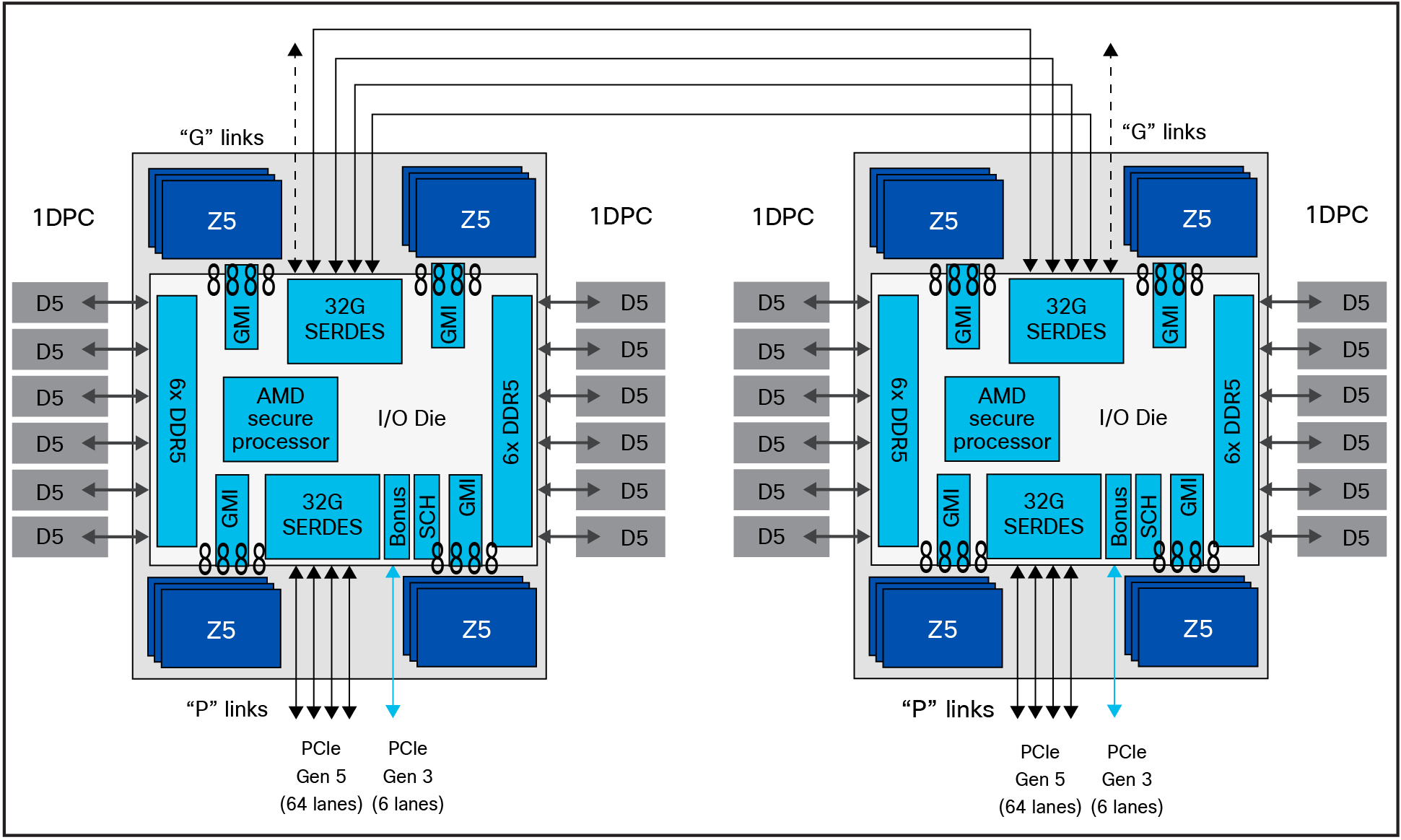
AMD EPYC 5th Gen processor block diagram with NUMA domains
NPS1
A setting of NPS=1 indicates a single NUMA node per socket. This setting configures all memory channels on the processor into a single NUMA node. All processor cores, all attached memory, and all PCIe devices connected to the SoC are in that one NUMA node. Memory is interleaved across all memory channels on the processor into a single address space.
NPS2
A setting of NPS=2 configures each processor into two NUMA domains that groups half of the cores and half of the memory channels into one NUMA domain, and the remaining cores and memory channels into a second NUMA domain. Memory is interleaved across the six memory channels in each NUMA domain. PCIe devices will be local to one of the two NUMA nodes depending on the half that has the PCIe root complex for that device.
NPS4
A setting of NPS=4 partitions the processor into four NUMA nodes per socket with each logical quadrant configured as its own NUMA domain. Memory is interleaved across the memory channels associated with each quadrant. PCIe devices will be local to one of the four processor NUMA domains, depending on the IOD quadrant that has the corresponding PCIe root complex for that device. Every pair of memory channels is interleaved. This is recommended for HPC and other highly parallel workloads. You must use NPS4 when booting Windows systems with CPU SMT enabled for AMD EPYC processors with more than 64 cores, because Windows limits the size of a CPU group to a maximum of 64 logical cores.
Note: For Windows systems, verify that the number of logical processors per NUMA node <=64 by using either NPS2 or NPS4 instead of the default NPS1.
NPS0 (not recommended)
A setting of NPS=0 indicates a single NUMA domain of the entire system (across both sockets in a two-socket configuration). This setting configures all memory channels on the system into a single NUMA node. Memory is interleaved across all memory channels on the system into a single address space. All processor cores across all sockets, all attached memory, and all PCIe devices connected to either processor is in that single NUMA domain.
Layer 3 cache as NUMA Domain
In addition to the NPS settings, one more BIOS option for changing NUMA configurations is available. With the Layer 3 Cache as NUMA (L3CAN) option, each Layer 3 cache (one per CCD) is exposed as its own NUMA node. For example, a single processor with 8 CCDs would have 8 NUMA nodes: one for each CCD. In this case, a two-socket system would have a total of 16 NUMA nodes.
This section describes the processor options you can configure.
CPU SMT Mode
You can set the CPU Simultaneous Multithreading (CPU SMT) option to enable or disable logical processor cores on processors that support the AMD CPU SMT mode option. When the CPU SMT mode is set to Auto (enabled), each physical processor core operates as two logical processor cores and allows multithreaded software applications to process threads in parallel within each processor.
Some workloads, including many HPC ones, observe a performance-neutral or even performance-negative result when CPU SMT is enabled. Some applications, and not just the physical core, are licensed by the hardware thread as enabled. For those reasons, disabling CPU SMT on your EPYC 9004 Series processor may be desirable. In addition, some operating systems do not have support for the x2APIC within the EPYC 9004 Series processor enabled, which is required to support beyond 255 threads. If you are running an operating system that does not support AMD’s x2APIC implementation, and you have two 64-core processors installed, you will need to disable CPU SMT. Table 3 summarizes the settings.
You should test the CPU hyperthreading option both enabled and disabled in your specific environment. If you are running a single-threaded application, you should disable hyperthreading.
Table 3. CPU SMT settings
|
Setting |
Options |
|
CPU SMT control |
●
Auto: uses two hardware threads per core
●
Disable: uses a single hardware thread per core
●
Enable: uses a double hardware thread per core
|
Secure Virtual Machine (SVM) mode
The Secure Virtual Machine (SVM) mode enables processor virtualization features and allows a platform to run multiple operating systems and applications in independent partitions. The AMD SVM mode can be set to either of the following values:
● Disabled: the processor does not permit virtualization.
● Enabled: the processor allows multiple operating systems in independent partitions.
If your application scenario does not require virtualization, then disable AMD virtualization technology. After virtualization is disabled, also disable the AMD IOMMU option, which can cause differences in latency for memory access. Table 4 summarizes the settings.
Table 4. Virtualization option settings
|
Setting |
Options |
|
SVM |
●
Enabled
●
Disabled
|
DF C-states
Much like CPU cores, the AMD Infinity Fabric can go into lower power states while idle. However, there will be a delay when changing back to full-power mode, causing some latency jitter. In a low-latency workload or one with bursty I/O, you can disable the Data Fabric (DF) C-states feature to achieve more performance, with a tradeoff of higher power consumption. Table 5 summarizes the settings.
Table 5. DF C-states
|
Setting |
Options |
|
DF C-states |
●
Auto/Enabled: allows the AMD Infinity Fabric to enter a
low-power state
●
Disabled: prevents the AMD Infinity Fabric from entering a
low-power state
|
ACPI SRAT L3 Cache as NUMA Domain
When the ACPI SRAT L3 Cache as NUMA Domain setting is enabled, each Layer-3 cache is exposed as a NUMA node. With the Layer 3 Cache as NUMA Domain (L3CAN) setting, each Layer-3 cache (one per CCD) is exposed as its own NUMA node. For example, a single processor with 8 CCDs would have 8 NUMA nodes: one for each CCD. A dual processor system would have a total of 16 NUMA nodes.
This setting can improve performance for highly NUMA-optimized workloads if workloads or components of workloads can be pinned to cores in a CCX and if they can benefit from sharing a Layer-3 cache. When this setting is disabled, NUMA domains are identified according to the NUMA NPS parameter setting.
Some operating systems and hypervisors do not perform Layer 3–aware scheduling, and some workloads benefit from having Layer 3 declared as a NUMA domain. Table 6 summarizes the settings.
Table 6. ACPI SRAT Layer 3 Cache as NUMA Domain settings
|
Setting |
Options |
|
ACPI SRAT L3 Cache As NUMA Domain |
●
Auto (disabled)
●
Disable: does not report each Layer-3 cache as a NUMA domain
to the OS
●
Enable: reports each Layer-3 cache as a NUMA domain to the OS
|
Algorithm Performance Boost Disable (APBDIS)
Allows you to select the Algorithm Performance Boost (APB) disable value for the SMU. In the default state, the AMD Infinity Fabric selects between a full-power and low-power fabric clock and memory clock, based on fabric and memory use. However, in certain scenarios involving low bandwidth but latency-sensitive traffic (and memory latency checkers), the transition from low power to full power can adversely affect latency. Setting APBDIS to 1 (to disable Algorithm Performance Boost [APB]) and specifying a fixed Infinity Fabric P-state of 0 will force the Infinity Fabric and memory controllers into full-power mode, eliminating any such latency jitter. Certain CPU processors and memory population options result in a scenario in which setting a fixed Infinity Fabric P- state of 1 will reduce memory latency at the expense of memory bandwidth. This setting may benefit applications known to be sensitive to memory latency. Table 7 summarizes the settings.
Table 7. APBDIS setting
|
Setting |
Options |
|
APBDIS |
●
Auto (0): sets an auto APBDIS for the SMU. This is the
default
option.
●
0: dynamically switches Infinity Fabric P-state based on link
use
●
1: enables fixed Infinity Fabric P-state control
|
Fixed SOC P-State SP5F 19h
Forces the P-state to be either independent or dependent, as reported by the ACPI _PSD object. It changes the SOC P-State if APBDIS is enabled. where, F refers to the processor family.
|
Setting |
Options |
|
Fixed SOC P-State SP5F 19h |
●
P0: highest-performing Infinity Fabric P-state
●
P1: next-highest-performing Infinity Fabric P-state
●
P2: next-highest-performing Infinity Fabric P-state after P1
|
xGMI settings: connection between sockets
In a two-socket system, the processors are interconnected through socket-to-socket xGMI links, part of the Infinity Fabric that connects all the components of the SoC together.
NUMA-unaware workloads may need maximum xGMI bandwidth because of extensive cross-socket communication. NUMA-aware workloads may want to minimize xGMI power because they do not have a lot of cross-socket traffic and prefer to use the increased CPU boost. The xGMI lane width can be reduced from x16 to x8 or x2, or an xGMI link can be disabled if power consumption is too high.
xGMI link configuration and 4-link xGMI max speed (Cisco xGMI max Speed)
You can set the number of xGMI links and maximum speed for the xGMI link. Setting this value to a lower speed can save uncore power that can be used to increase core frequency or reduce overall power. It also decreases cross-socket bandwidth and increases cross-socket latency. The Cisco UCS C245 M8 Rack Server supports four xGMI links with a maximum speed of 32 Gbps.
Cisco xGMI max Speed settings allow to configure xGMI Link configuration and 4-Link/3-Link xGMI Max Speed. Enabling Cisco xGMI max speed will set xGMI Link Configuration to 4, and 4-Link xGMI Max Speed is 32 Gbps. Disabling Cisco xGMI Max Speed settings will apply the default values.
Table 8 summarizes the settings.
Table 8. xGMI link settings
|
Setting |
Options |
|
Cisco xGMI Max Speed |
●
Disabled (default)
●
Enabled
|
|
xGMI Link Configuration |
●
Auto
●
1
●
2
●
3
●
4
|
|
4-Link xGMI Max Speed |
●
Auto (25 Gbps)
●
20 Gbps
●
25 Gbps
●
32 Gbps
|
|
3-Link xGMI Max Speed |
●
Auto (25 Gbps)
●
20 Gbps
●
25 Gbps
●
32 Gbps
|
Note: This BIOS feature is applicable only to Cisco UCS X215c M8 Compute Nodes and Cisco UCS C245 M8 Rack Servers with 2-socket configurations.
Enhanced CPU performance
This BIOS option helps users modify the enhanced CPU performance settings. When it is enabled, this option adjusts the processor settings and enables the processor to run aggressively, which can improve overall CPU performance but may result in higher power consumption. Values for this BIOS option can be Auto or Disabled. By default, the enhanced CPU performance option is disabled.
Note: This BIOS feature is applicable only to Cisco UCS X215c M8 Compute Nodes and Cisco UCS C245 M8 Rack Servers. When this option is enabled, we highly recommend setting the fan policy at maximum power.
By default, this BIOS setting is Disabled.
You can configure the Memory settings described in this section.
NUMA Nodes Per Socket (NPS)
This setting lets you specify the number of desired NUMA Nodes Per Socket (NPS) and enables a tradeoff between reducing local memory latency for NUMA-aware or highly parallelizable workloads and increasing per-core memory bandwidth for non-NUMA-friendly workloads. Socket interleave (NPS0) will attempt to interleave the two sockets together into one NUMA node. 4th Gen AMD EPYC processors support a varying number of NUMA NPS values depending on the internal NUMA topology of the processor. NPS2 and NPS4 may not be options on certain processors or with certain memory populations.
In one-socket servers, the number of NUMA nodes per socket can be 1, 2, or 4, though not all values are supported by every processor. Performance for applications that are highly NUMA-optimized can be improved by setting the number of NUMA nodes per socket to a supported value greater than 1.
The default configuration (one NUMA Domain per socket) is recommended for most workloads. NPS4 is recommended for High-Performance Computing (HPC) and other highly parallel workloads. When using 200-Gbps network adapters, NPS2 may be preferred to provide a compromise between memory latency and memory bandwidth for the Network Interface Card (NIC). This setting is independent of the Advanced Configuration and Power Interface (ACPI) Static Resource Affinity Table (SRAT) Layer- 3 (L3) cache as a NUMA Domain setting. When ACPI SRAT L3 Cache as NUMA Domain is enabled, this setting then determines the memory interleaving granularity. With NPS1, all eight memory channels are interleaved. With NPS2, every four channels are interleaved with each other. With NPS4, every pair of channels is interleaved. Table 9 summarizes the settings.
Table 9. NUMA NPS settings
|
Setting |
Options |
|
NUMA Nodes per Socket |
●
Auto (NPS1)
●
NPS0: interleave memory accesses across all channels in both
sockets (not recommended).
●
NPS1: interleave memory accesses across all eight channels in
each socket; reports one NUMA node per socket (unless L3 Cache
as NUMA is enabled).
●
NPS2: interleave memory accesses across groups of four
channels (ABCD and EFGH) in each socket; reports two NUMA
nodes per socket (unless L3 Cache as NUMA is enabled).
●
NPS4: interleave memory accesses across pairs of channels
(AB, CD, EF, and GH) in each socket; reports four NUMA nodes
per socket (unless L3 Cache as NUMA is enabled).
|
I/O Memory Management Unit (IOMMU)
The I/O Memory Management Unit (IOMMU) provides several benefits and is required when using x2 programmable interrupt controller (x2APIC). Enabling the IOMMU allows devices (such as the EPYC integrated SATA controller) to present separate interrupt requests (IRQs) for each attached device instead of one IRQ for the subsystem. The IOMMU also allows operating systems to provide additional protection for Direct Memory Access (DMA)–capable I/O devices. IOMMU also helps filter and remap interrupts from peripheral devices. Table 10 summarizes the settings.
Table 10. IOMMU settings
|
Setting |
Options |
|
IOMMU |
●
Auto (enabled)
●
Disabled: disable IOMMU support
●
Enabled: enable IOMMU support
|
Memory interleaving
Memory interleaving is a technique that CPUs use to increase the memory bandwidth available for an application. Without interleaving, consecutive memory blocks, often cache lines, are read from the same memory bank. Software that reads consecutive memory thus will need to wait for a memory transfer operation to complete before starting the next memory access. With memory interleaving enabled, consecutive memory blocks are in different banks, and so all of them can contribute to the overall memory bandwidth that a program can achieve.
AMD recommends that all eight memory channels per CPU socket be populated with all channels having equal capacity. This approach enables the memory subsystem to operate in eight-way interleaving mode, which should provide the best performance in most cases. Table 11 summarizes the settings.
Table 11. Memory interleaving settings
|
Setting |
Options |
|
Memory interleaving |
●
Enabled: interleaving is enabled with supported memory DIMM
configuration.
●
Disable: no interleaving is performed.
|
You can configure the power state settings described in this section.
Core performance boost
The core performance boost feature allows the processor to transition to a higher frequency than the CPU’s base frequency, based on the availability of power, thermal headroom, and the number of active cores in the system. Core performance boost can cause jitter due to frequency transitions of the processor cores.
Some workloads do not need to be able to run at the maximum core frequency to achieve acceptable levels of performance. To obtain better power efficiency, you can set a maximum core boost frequency. This setting does not allow you to set a fixed frequency; it only limits the maximum boost frequency. Actual boost performance depends on many factors and other settings mentioned in this document. Table 12 summarizes the settings.
Table 12. Core performance boost settings
|
Setting |
Options |
|
Core performance boost |
●
Auto (enabled): allows the processor to transition to a
higher frequency (turbo frequency) than the CPU’s base
frequency
●
Disabled: disables the CPU core boost frequency
|
Global C-state control
C-states are a processor’s CPU core inactive power states. C0 is the operational state in which instructions are processed, and higher numbered C-states (C1, C2, etc.) are low-power states in which the core is idle. The Global C-state setting can be used to enable and disable C-states on the server. By default, the global C-state control is set to Auto, which enables cores to enter lower power states; this can cause jitter due to frequency transitions of the processor cores. When this setting is disabled, the CPU cores will operate at the C0 and C1 states. Table 13 summarizes the settings.
C-states are exposed through ACPI objects and can be dynamically requested by software. Software can request a C-state change either by executing a HALT instruction or by reading from a particular I/O address. The actions taken by the processor when entering the low-power C-state can also be configured by software. The 4th Gen AMD EPYC processor’s core is designed to support as many as three AMD-specified C-states: I/O-based C0, C1, and C2.
Table 13. Global C-state settings
|
Setting |
Options |
|
Global C-state control |
●
Auto (enabled): enables I/O-based C-states
●
Disabled: disables I/O-based C-states
|
Layer-1 and Layer-2 stream hardware prefetchers
Most workloads benefit from the use of Layer-1 and Layer-2 stream hardware prefetchers (L1 Stream HW Prefetcher and L2 Stream HW Prefetcher) to gather data and keep the core pipeline busy. However, some workloads are very random in nature and will actually achieve better overall performance if one or both of the prefetchers are disabled. By default, both prefetchers are enabled. Table 14 summarizes the settings.
Table 14. Layer-1 and Layer-2 stream hardware prefetcher settings
|
Setting |
Options |
|
L1 Stream HW Prefetcher |
●
Auto (Enabled)
●
Disable: disables prefetcher
●
Enable: enables prefetcher
|
|
L2 Stream HW Prefetcher |
●
Auto (Enabled)
●
Disable: disables prefetcher
●
Enable: enables prefetcher
|
Determinism slider
The Determinism slider allows to select between uniform performance across identically configured systems in a data center, by setting the server to the Performance setting, or the maximum performance of any individual system but with varying performance across the data center, by setting the server to the Power setting. When the Determinism slider is set to Performance, be sure that the configurable Thermal Design Power (cTDP) and Package Power Limit (PPL) are set to the same value. The default (Auto) setting for most processors is the Performance determinism mode, allowing the processor to operate at a lower power level with consistent performance. For maximum performance, set the Determinism slider to Power. Table 15 summarizes the settings.
Table 15. Determinism slider settings
|
Setting |
Options |
|
Determinism slider |
●
Auto: this setting is equal to the Performance option.
●
Power: ensures maximum performance levels for each CPU in a
large population of identically configured CPUs by throttling
CPUs only when they reach the same cTDP
●
Performance: ensures consistent performance levels across a
large population of identically configured CPUs by throttling
some CPUs to operate at a lower power level
|
CPPC: Collaborative Processor Performance Control
Collaborative Processor Performance Control (CPPC) was introduced with ACPI 5.0 as a mode to communicate performance between an operating system and the hardware. This mode can be used to allow the OS to control when and how much turbo boost can be applied in an effort to maintain energy efficiency. Not all operating systems support CPPC, but Microsoft began support with Microsoft Windows 2016 and later. Table 16 summarizes the settings.
Table 16. CPPC settings
|
Setting |
Options |
|
CPPC |
●
Auto
●
Disabled: disabled
●
Enabled: allows the OS to make performance and power
optimization requests using ACPI CPPC
|
Power profile selection F19h
The DF P-state selection in the profile policy is overridden by the P-state range, the BIOS option, or the APB_DIS BIOS option, where F refers to the processor family and M denotes the model.
|
Settings |
Options |
|
Power profile selection F19h |
●
Efficiency mode
●
High-performance mode
●
Maximum I/O performance mode
●
Balanced memory performance mode
●
Balanced core performance mode
●
Balanced core memory performance mode
●
Auto
|
Fan control policy
Fan policy enables you to control the fan speed to reduce server power consumption and noise levels. Prior to the use of fan policy, the fan speed increased automatically when the temperature of any server component exceeded the set threshold. To help ensure that the fan speeds were low, the threshold temperatures of components were usually set to high values. Although this behavior suited most server configurations, it did not address the following situations:
● Maximum CPU performance: For high performance, certain CPUs must be cooled substantially below the set threshold temperature. This cooling requires very high fan speeds, which results in increased power consumption and noise levels.
● Low power consumption: To help ensure the lowest power consumption, fans must run very slowly and, in some cases, stop completely on servers that allow this behavior. But slow fan speeds can cause servers to overheat. To avoid this situation, you need to run fans at a speed that is moderately faster than the lowest possible speed.
You can choose the following fan policies:
● Balanced: This is the default policy. This setting can cool almost any server configuration, but it may not be suitable for servers with PCIe cards, because these cards overheat easily.
● Low Power: This setting is well suited for minimal-configuration servers that do not contain any PCIe cards.
● High Power: This setting can be used for server configurations that require fan speeds ranging from 60 to 85 percent. This policy is well suited for servers that contain PCIe cards that easily overheat and have high temperatures. The minimum fan speed set with this policy varies for each server platform, but it is approximately in the range of 60 to 85 percent.
● Maximum Power: This setting can be used for server configurations that require extremely high fan speeds ranging between 70 and 100 percent. This policy is well suited for servers that contain PCIe cards that easily overheat and have extremely high temperatures. The minimum fan speed set with this policy varies for each server platform, but it is approximately in the range of 70 to 100 percent.
● Acoustic: The fan speed is reduced to reduce noise levels in acoustic-sensitive environments. Rather than regulating energy consumption and preventing component throttling as in other modes, the Acoustic option could result in short-term throttling to achieve a lowered noise level. Applying this fan control policy may result in short-duration transient performance impacts.
Note: This policy is configurable for standalone Cisco UCS C-Series M8 servers using the Cisco Integrated Management Controller (IMC) console and the Cisco IMC supervisor. From the Cisco IMC web console, choose Compute > Power Policies > Configured Fan Policy > Fan Policy.
For Cisco Intersight®–managed C-Series M8 servers, this policy is configurable using fan policies.
BIOS settings for Cisco UCS X215c M8 Compute Nodes, Cisco UCS C245 M8 Rack Servers, and Cisco UCS C225 M8 Rack Servers
Table 17 lists the BIOS token names, defaults, and supported values for the Cisco UCS M8 servers with the AMD EPYC 4th gen and 5th Gen processor families.
Table 17. BIOS token names and values
|
BIOS token name |
Default value |
Supported values |
|
Processor |
||
|
CPU SMT mode |
Auto (enabled) |
Auto, Enabled, Disabled |
|
SVM mode |
Enabled |
Enabled, Disabled |
|
DF C-states |
Auto (enabled) |
Auto, Enabled, Disabled |
|
ACPI SRAT L3 Cache as NUMA Domain |
Auto (disabled) |
Auto, Enabled, Disabled |
|
APBDIS |
Auto (0) |
Auto, 0, 1 |
|
Fixed SOC P-State SP5F 19h |
P0 |
P0, P1, P2 |
|
4-link xGMI max speed* |
Auto (32Gbps) |
Auto, 20Gbps, 25Gbps, 32Gbps |
|
Enhanced CPU performance* |
Disabled |
Auto, Disabled |
|
Memory |
||
|
NUMA nodes per socket |
Auto (NPS1) |
Auto, NPS0, NPS1, NPS2, NPS4 |
|
IOMMU |
Auto (enabled) |
Auto, Enabled, Disabled |
|
Memory interleaving |
Auto (enabled) |
Auto, Enabled, Disabled |
|
Power/performance |
||
|
Core performance boost |
Auto (enabled) |
Auto, Disabled |
|
Global C-state control |
Disabled |
Auto, Enabled, Disabled |
|
L1 Stream HW Prefetcher |
Auto (enabled) |
Auto, Enabled, Disabled |
|
L2 Stream HW Prefetcher |
Auto (enabled) |
Auto, Enabled, Disabled |
|
Determinism slider |
Auto (power) |
Auto, Power, Performance |
|
CPPC |
Auto (disabled) |
Auto, Disabled, Enabled |
|
Power profile selection F19h |
High-performance mode |
Balanced memory performance mode, efficiency mode, high-performance mode, maximum I/O performance mode, balanced core performance mode, balanced core memory performance mode |
BIOS recommendations for various general-purpose workloads
This section summarizes the BIOS settings recommended to optimize general-purpose workloads:
● Computation-intensive
● I/O-intensive
● Energy efficiency
● Low latency
The following sections describe each workload.
CPU intensive workloads
For CPU intensive workloads, the goal is to distribute the work for a single job across multiple CPUs to reduce the processing time as much as possible. To do this, you need to run portions of the job in parallel. Each process, or thread, handles a portion of the work and performs the computations concurrently. The CPUs typically need to exchange information rapidly, requiring specialized communication hardware.
CPU intensive workloads generally benefit from processors or memory that achieves the maximum turbo frequency for any individual core at any time. Processor power management settings can be applied to help ensure that any component frequency increase can be readily achieved. CPU intensive workloads are general-purpose workloads, so optimizations are performed generically to increase processor core and memory speed, and performance tunings that typically benefit from faster computing time are used.
I/O-intensive workloads
I/O-intensive optimizations are configurations that depend on maximum throughput between I/O and memory. Processor utilization–based power management features that affect performance on the links between I/O and memory are disabled.
Energy-efficient workloads
Energy-efficient optimizations are the most common balanced performance settings. They benefit most application workloads while also enabling power management settings that have little impact on overall performance. The settings that are applied for energy-efficient workloads increase general application performance rather than power efficiency. Processor power management settings can affect performance when virtualization operating systems are used. Hence, these settings are recommended for customers who do not typically tune the BIOS for their workloads.
Low-latency workloads
Workloads that require low latency, such as financial trading and real-time processing, require servers to provide a consistent system response. Low-latency workloads are for customers who demand the least amount of computational latency for their workloads. Maximum speed and throughput are often sacrificed to lower overall computational latency. Processor power management and other management features that might introduce computational latency are disabled.
To achieve low latency, you need to understand the hardware configuration of the system under test. Important factors affecting response times include the number of cores, the processing threads per core, the number of NUMA nodes, the CPU and memory arrangements in the NUMA topology, and the cache topology in a NUMA node. BIOS options are generally independent of the OS, and a properly tuned low-latency operating system is also required to achieve deterministic performance.
Summary of BIOS settings optimized for general-purpose workloads
Table 18 summarizes BIOS settings optimized for general-purpose workloads.
Table 18. BIOS recommendations for CPU intensive, I/O-intensive, energy-efficiency, and low-latency workloads
|
BIOS options |
BIOS values (platform default) |
CPU intensive |
I/O intensive |
Energy efficiency |
Low latency |
|
Processor |
|||||
|
CPU SMT mode |
Auto (enabled) |
Auto |
Auto |
Auto |
Disabled |
|
SVM mode |
Enabled |
Enabled |
Enabled |
Enabled |
Disabled |
|
DF C-states |
Auto (enabled) |
Auto |
Disabled |
Auto |
Disabled |
|
ACPI SRAT L3 Cache as NUMA Domain |
Auto (disabled) |
Enabled |
Auto |
Auto |
Auto |
|
APBDIS |
Auto (0) |
1 |
1 |
Auto |
Auto |
|
Fixed SOC P-State SP5F 19h |
P0 |
P0 |
P0 |
P2 |
P0 |
|
4-link xGMI max speed |
Auto (32Gbps) |
Auto |
Auto |
Auto |
Auto |
|
Enhanced CPU performance |
Disabled |
Auto |
Disabled |
Disabled |
Disabled |
|
Memory |
|||||
|
NUMA nodes per socket |
Auto (NPS1) |
NPS4 |
NPS4 |
Auto |
Auto |
|
IOMMU |
Auto (enabled) |
Auto* |
Auto |
Auto |
Disabled* |
|
Memory interleaving |
Auto (enabled) |
Auto* |
Auto |
Auto |
Disabled* |
|
Power/performance |
|||||
|
Core performance boost |
Auto (enabled) |
Auto |
Auto |
Auto |
Disabled |
|
Global C-State control |
Disabled |
Disabled |
Enabled |
Enabled |
Disabled |
|
L1 Stream HW Prefetcher |
Auto (enabled) |
Auto |
Auto |
Disabled |
Auto |
|
L2 Stream HW Prefetcher |
Auto (enabled) |
Auto |
Auto |
Disabled |
Auto |
|
Determinism slider |
Auto (power) |
Auto |
Auto |
Auto |
Performance |
|
CPPC |
Auto (disabled) |
Auto |
Auto |
Enabled |
Auto |
|
Power profile selection F19h |
High-performance mode |
High-performance mode |
Maximum I/O performance mode |
Efficiency mode |
High-performance mode |
Note: BIOS tokens with*highlighted are applicable only for Cisco UCS X215c M8 Compute Nodes and Cisco UCS C245 M8 Rack Servers.
● If your application scenario does not require virtualization, then disable AMD virtualization technology. With virtualization disabled, also disable the AMD IOMMU option. It can cause differences in latency for memory access. See the AMD performance tuning guide for more information.
Additional BIOS recommendations for enterprise workloads
This section summarizes optimal BIOS settings for enterprise workloads:
● Virtualization
● Containers
● Relational Database (RDBMS)
● Analytical Database (Bigdata)
● HPC workloads
The following sections describe each enterprise workload.
Virtualization workloads
AMD Virtualization Technology provides manageability, security, and flexibility in IT environments that use software-based virtualization solutions. With this technology, a single server can be partitioned and can be projected as several independent servers, allowing the server to run different applications on the operating system simultaneously. It is important to enable AMD Virtualization Technology in the BIOS to support virtualization workloads.
The CPUs that support hardware virtualization enable the processor to run multiple operating systems in the virtual machines. This feature involves some overhead because the performance of a virtual operating system is comparatively slower than that of the native OS.
For more information, see AMD’s VMware vSphere Tuning Guide.
Container workloads
Containerizing an application platform and its associated dependencies abstracts the underlying infrastructure and OS differences for efficiency. Each container is bundled into one package containing an entire runtime environment, including an application with all its dependencies, libraries and other binaries, and configuration files needed to run that application. Containers running applications in a production environment need management to ensure consistent uptime. If a container goes down, then another container needs to start automatically.
Workloads that scale and perform well on bare metal should see a similar scaling curve in a container environment with minimal performance overhead. Some containerized workloads can even see close to 0% performance variance compared to bare metal. Large overhead generally means that application settings and/or container configuration are not optimally set. These topics are beyond the scope of this tuning guide. However, the CPU load balancing behavior of Kubernetes or other container orchestration platform scheduler may assign or load balance containerized applications differently than in a bare metal environment.
For more information, see AMD’s Kubernetes Container Tuning Guide.
Relational Database workloads
Integrating RDBMS like Oracle, MySQL, PostgreSQL, or Microsoft SQL Server with AMD EPYC processors can lead to improved database performance, especially in environments that require high concurrency, rapid query processing, and efficient resource utilization. The architecture of AMD EPYC processors allows databases to leverage multiple cores and threads effectively, which is especially beneficial for transactional workloads, analytics, and large-scale data processing.
In summary, using AMD EPYC processors in RDBMS environments can lead to significant improvements in performance, scalability, and cost-efficiency, making it a strong choice for enterprise database solutions.
4th Gen AMD EPYC processors deliver high Input/Output Operations Per Second (IOPS) and throughput for all databases. Selecting the right CPU is important for archiving optimal database application performance.
For more information, see AMD’s RDBMS Tuning Guide.
Big Data Analytics workloads
Big Data Analytics involves the examination of vast amounts of data to uncover hidden patterns, correlations, and other insights that can be used to make better decisions. This requires significant computational power, memory capacity, and I/O bandwidth—areas where AMD EPYC processors excel.
AMD EPYC processors provide a robust platform for Big Data Analytics, offering the computational power, memory capacity, and I/O bandwidth necessary to handle the demands of large-scale data processing. Their scalability, cost efficiency, and energy efficiency make them a compelling choice for organizations looking to build or upgrade their Big Data Analytics infrastructure.
HPC (High-performance computing) workloads
HPC refers to cluster-based computing that uses multiple individual nodes that are connected and that work in parallel to reduce the amount of time required to process large data sets that would otherwise take exponentially longer to run on any one system. HPC workloads are computation intensive and typically also network-I/O intensive. HPC workloads require high-quality CPU components and high-speed, low-latency network fabrics for their Message Passing Interface (MPI) connections.
Computing clusters include a head node that provides a single point for administering, deploying, monitoring, and managing the cluster. Clusters also have an internal workload management component, known as the scheduler, which manages all incoming work items (referred to as jobs). Typically, HPC workloads require large numbers of nodes with nonblocking MPI networks so that they can scale. Scalability of nodes is the single most important factor in determining the achieved usable performance of a cluster.
HPC requires a high-bandwidth I/O network. When you enable Direct Cache Access (DCA) support, network packets go directly into the Layer 3 processor cache instead of the main memory. This approach reduces the number of HPC I/O cycles generated by HPC workloads when certain Ethernet adapters are used, which in turn increases system performance.
For more information, see AMD’s High-Performance Computing (HPC) Tuning Guide.
Summary of BIOS settings recommended for enterprise workloads
Table 19 summarizes the BIOS tokens and settings recommended for various enterprise workloads.
Table 19. BIOS recommendations for virtualization, containers, RDBMS, big-data analytics, and HPC enterprise workloads
|
BIOS options |
BIOS values (platform default) |
Virtualization/ container |
RDBMS |
Big-data analytics |
HPC |
|
Processor |
|||||
|
CPU SMT mode |
Enabled |
Enabled |
Enabled |
Disabled |
Disabled |
|
SVM mode |
Enabled |
Enabled |
Enabled |
Enabled |
Enabled |
|
DF C-states |
Auto (Enabled) |
Auto |
Disabled |
Auto |
Auto |
|
ACPI SRAT L3 Cache as NUMA Domain |
Auto (Disabled) |
Auto |
Auto |
Auto |
Auto |
|
APBDIS |
Auto (0) |
Auto |
1 |
1 |
1 |
|
Fixed SOC P-State SP5F 19h |
P0 |
P0 |
P0 |
P0 |
P0 |
|
4-link xGMI max speed* |
Auto (32Gbps) |
Auto |
Auto |
Auto |
Auto |
|
Enhanced CPU performance* |
Disabled |
Disabled |
Disabled |
Disabled |
Auto |
|
Memory |
|||||
|
NUMA nodes per socket |
Auto (NPS1) |
Auto |
NPS4 |
Auto |
NPS4 |
|
IOMMU |
Auto (Enabled) |
Auto |
Auto |
Auto |
Auto |
|
Memory interleaving |
Auto (Enabled) |
Auto |
Auto |
Auto |
Auto |
|
Power/performance |
|||||
|
Core performance boost |
Auto (Enabled) |
Auto |
Auto |
Auto |
Auto |
|
Global C-State control |
Disabled |
Enabled |
Enabled |
Enabled |
Enabled |
|
L1 Stream HW Prefetcher |
Auto (Enabled) |
Auto |
Auto |
Auto |
Auto |
|
L2 Stream HW Prefetcher |
Auto (Enabled) |
Auto |
Auto |
Auto |
Auto |
|
Determinism slider |
Auto (Power) |
Auto |
Auto |
Auto |
Auto |
|
CPPC |
Auto (Disabled) |
Enabled |
Auto |
Enabled |
Auto |
|
Power profile selection F19h |
High-performance mode |
High-performance mode |
Maximum I/O performance mode |
High-performance mode |
High-performance mode |
Note: BIOS tokens with*highlighted are not applicable only for single socket optimized platform like Cisco UCS C225 M8 1U Rack Server.
● If your workloads have few vCPUs per virtual machine (that is, less than a quarter of the number of cores per socket), then the following settings tend to provide the best performance:
◦ NUMA NPS (nodes per socket) = 4
◦ LLC As NUMA turned on
● If your workload virtual machines have a large number of vCPUs (that is, greater than half the number of cores per socket), then the following settings tend to provide the best performance:
◦ NUMA NPS (nodes per socket) = 1
◦ LLC As NUMA turned off
For more information, see the VMware vSphere Tuning Guide.
Operating system tuning guidance for high performance
Microsoft Windows, VMware ESXi, Red Hat Enterprise Linux, and SUSE Linux operating systems come with a lot of new power management features that are enabled by default. Hence, you must tune the operating system to achieve the best performance.
For additional performance documentation, see the AMD EPYC performance tuning guides.
The CPUfreq governor defines the power characteristics of the system CPU, which in turn affects CPU performance. Each governor has its own unique behavior, purpose, and suitability in terms of workload.
The performance governor forces the CPU to use the highest possible clock frequency. This frequency is statically set and does not change. Therefore, this particular governor offers no power-savings benefit. It is suitable only for hours of heavy workload, and even then, only during times in which the CPU is rarely (or never) idle. The default setting is “on demand,” which allows the CPU to achieve the maximum clock frequency when the system load is high, and the minimum clock frequency when the system is idle. Although this setting allows the system to adjust power consumption according to system load, it does so at the expense of latency from frequency switching.
The performance governor can be set using the cpupower command:
cpupower frequency-set -g performance
For additional information, see the following links:
● Red Hat Enterprise Linux: Set the performance CPUfreq governor.
● SUSE Enterprise Linux Server: Set the performance CPUfreq governor.
Microsoft Windows Server 2019 and 2022
For Microsoft Windows Server 2019, by default, the Balanced (recommended) power plan is used. This setting enables energy conservation, but it can cause increased latency (slower response time for some tasks), and it can cause performance problems for CPU-intensive applications. For maximum performance, set the power plan to High Performance.
For additional information, see the following link:
● Microsoft Windows and Hyper-V: Set the power policy to High Performance.
In VMware ESXi, host power management is designed to reduce the power consumption of ESXi hosts while they are powered on. Set the power policy to High Performance to achieve the maximum performance.
For additional information, see the following links:
● VMware ESXi: Set the power policy to High Performance.
When tuning system BIOS settings for performance, you need to consider a number of processor and memory options. If the best performance is your goal, be sure to choose options that optimize performance in preference to power savings. Also experiment with other options, such as memory interleaving and CPU hyperthreading. Most important, assess the impact of any settings on the performance that your applications need.
For more information about the Cisco UCS M8 Server with the AMD 4th gen & 5th gen processors, see the following resources:
● IMM BIOS token guide:
● Cisco UCS X215c M8 Compute Node:
● Cisco UCS C245 M8 Rack Server:
● Cisco UCS C225 M8 Rack Server:
● AMD EPYC tuning guides:
◦ https://developer.amd.com/resources/epyc-resources/epyc-tuning-guides/