Overview
The Cisco N9396T12C-SE1 switch is a fixed port switch that occupies two rack units (RU). It is designed for deployment in data centers.
Media Access Control Security (MACsec) is supported on all ports. The switch includes these ports:
-
96 10G RJ45 ports
-
12 40/100-Gigabit QSFP28 ports
-
2 management ports (one RJ45 port and one SFP port)
-
1 console port
-
1 USB port
This switch includes these user-replaceable components:
-
Fan modules (three) with these airflow choices:
-
Port-side-exhaust fan module with blue coloring (NXA-SFAN-160CFM2PE)
-
Port-side-intake fan module with red coloring (NXA-SFAN-160CFM2PI)
-
 Note |
|
Note |
|
-
Power supply modules (two—one for operations and one for redundancy [1+1]) with these choices:
-
1400-W port-side exhaust AC power supply with blue coloring (NXA-PAC-1400W-PE)
-
1400-W port-side intake AC power supply with red coloring (NXA-PAC-1400W-PI)
-
2000-W port-side intake DC power supply with red coloring (NXA-PDC-2KW-PI)
Note
-
A mix of AC and DC power supplies in the same switch are supported for hot swapping purposes within a time limit of 15 minutes.
-
All the fan modules and power supplies must use the same airflow direction.
-
The figure shows the switch features on the port side of the chassis.
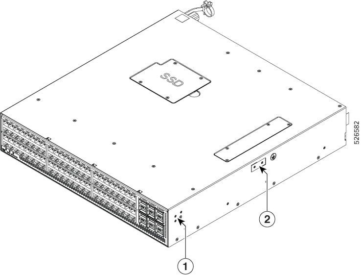
The table presents the switch features on the port side of the chassis.
|
1 |
Screw holes for front mounting brackets (left and right sides) |
2 |
Grounding pad |
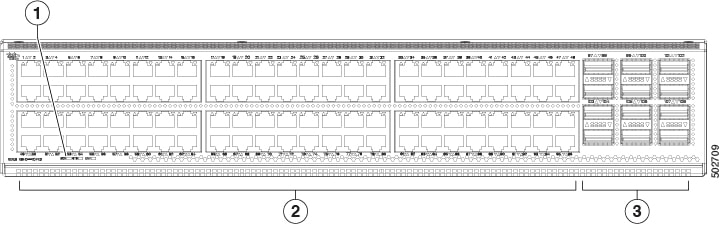
The figure illustrates the switch features on the port side of the chassis.
|
1 |
Beacon (BCN), Status (STS), and Environment (ENV) LEDs |
3 |
12 40/100-Gigabit QSFP28 ports |
|
2 |
96 10G RJ45 ports |
To determine which transceivers, adapters, and cables are supported by this switch, see the Cisco Transceiver Modules Compatibility Information document.
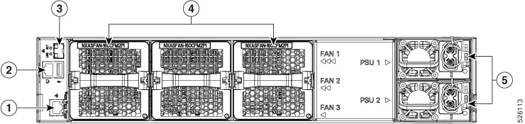
The figure illustrates the switch features on the power supply side of the chassis.
|
1 |
Management port (1—RJ-45 copper port). |
4 |
Fan modules (3) with slots numbered from 1 (left) to 3 (right). |
|
2 |
Console management ( 1 —RJ-45 copper port) and USB port (1). |
5 |
AC power supply modules (2) with slots numbered 1 (top) and 2 (bottom). |
|
3 |
1—SFP optical port |
You can order fan and power supply modules with port-side intake or port-side exhaust airflow, based on your port positioning. Fan and AC power supply modules have red coloring for port-side intake airflow. For port-side exhaust airflow, fan and AC power supply modules have blue coloring.
The fan and power supply modules are field-replaceable.
You can replace one fan module or one power supply module during operation if all other modules are installed and functioning.
If only one power supply is installed, insert the replacement into the open slot before you remove the original unit.
Note |
All fan and power supply modules must be installed with the same airflow direction. If they differ, the switch can overheat and shut down. |
 Caution |
If the switch has port-side intake airflow (red coloring for fan modules), you must locate the ports in the cold aisle. If the switch has port-side exhaust airflow (blue coloring for fan modules), you must locate the ports in the hot aisle. If you locate the air intake in a hot aisle, the switch can overheat and shut down. |
 Feedback