System Configuration

This chapter explains how to configure system configuration settings on the Secure Firewall Management Center.

Integrate Firewall Management Center with Cisco Security Cloud

An integration of Firewall Management Center with Cisco Security Cloud is a security management solution that

  • connects firewall deployments to Cisco's integrated security cloud services for a consistent experience,

  • unifies visibility, enables automation, and strengthens security across network, endpoints, and applications, and

  • offers a platform approach with simpler, more integrated cloud services that reduce the complexity of managing multiple products.

Integration features

The integration provides these capabilities:

  • A centralized view of inventory across Firewall Management Centers.

  • Zero-Touch Provisioning for Firewall Threat Defense.

  • Cross-launching to the Firewall Management Center to manage devices and objects.

  • Help with establishing consistent policies across Firewall Management Centers.

  • Cloud event storage and services to enrich threat hunts and investigations.

Use your Security Cloud Control account to authorize and register (onboard) your Firewall Management Center; Onboard an On-Prem Management Center.

To integrate the Secure Firewall Management Center with Cisco XDR, refer to the Cisco Secure Firewall Management Center and Cisco XDR Integration Guide.

Enable SecureX integration

Enable SecureX integration to connect your management center and managed devices to a Cisco Defense Orchestrator (CDO) tenant, allowing for centralized cloud-based management and enhanced security capabilities.

  • Centralizes device management and event forwarding through the cloud.

  • Provides access to Cisco Security Cloud features such as AI Assistant, Policy Analyzer, XDR Automation, and Zero-Touch Provisioning.

Use this task when you need to onboard your management center and its managed devices to a CDO tenant for integration with Cisco Security Cloud services.

This integration is relevant for organizations seeking to leverage Cisco cloud-based security features, streamline device management, and enable advanced automation and analytics. Perform this task during initial setup or when adding new devices to your Cisco Security Cloud environment.

Before you begin

  • Security Cloud Control uses Cisco Security Cloud Sign On as its identity provider and Duo for multifactor authentication. Ensure that you have your Cisco Security Cloud Sign On credentials and can sign in to the Cisco regional cloud where your account was created.

  • You need a Security Cloud Control tenant to integrate the Secure Firewall Management Center with Cisco Security Cloud. If you do not already have aSecurity Cloud Control tenant, request one or create a tenant during this workflow. For more information, refer to Request a Security Cloud Control Tenant.

  • Link your Security Cloud Control tenant, the one you want to use for onboarding the management center, to your Security Services Exchange (SSE) account. For more information, refer to Link Your Security Cloud Control and Cisco XDR Tenant Accounts.

Follow these steps to enable SecureX integration:

Procedure


Step 1

In the Secure Firewall Management Center, choose Integration > SecureX.

Step 2

Choose a Cisco regional cloud from the Current Region drop-down list.

This cloud is also used for Cisco Success Network, Cisco Support Diagnostics, and the Secure Network Analytics cloud using Security Analytics and Logging (SaaS). If you are registered to the Smart Software Manager, your region is preselected.

Step 3

Click Enable SecureX.

A separate browser tab opens to log you in to your Security Cloud Control account. Make sure this page is not blocked by a pop-up blocker.
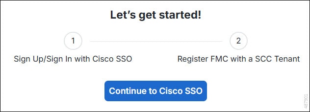
Step 4

Click Continue to Cisco SSO.

Figure 1. Welcome Page
A screen capture of welcome page displaying two steps of the integration workflow.

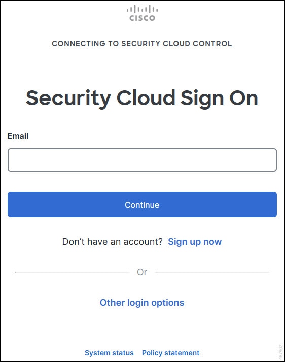
Step 5

Log in to your Security Cloud Control account.

Figure 2. Security Cloud Control Sign On
A screen capture of A screen capture of Security Cloud Control sign on page prompting to enter email address. sign on page prompting to enter email address.

If you do not have a Security Cloud Sign On account to log in to Security Cloud Control and you want to create one, click Sign up now in the Security Cloud Sign On page. Refer to Create a New Cisco Security Cloud Sign On Account.

Step 6

Choose a Security Cloud Control tenant that you want to use for this integration. The Secure Firewall Management Center and the managed devices get onboarded to the Security Cloud Control tenant that you choose here.
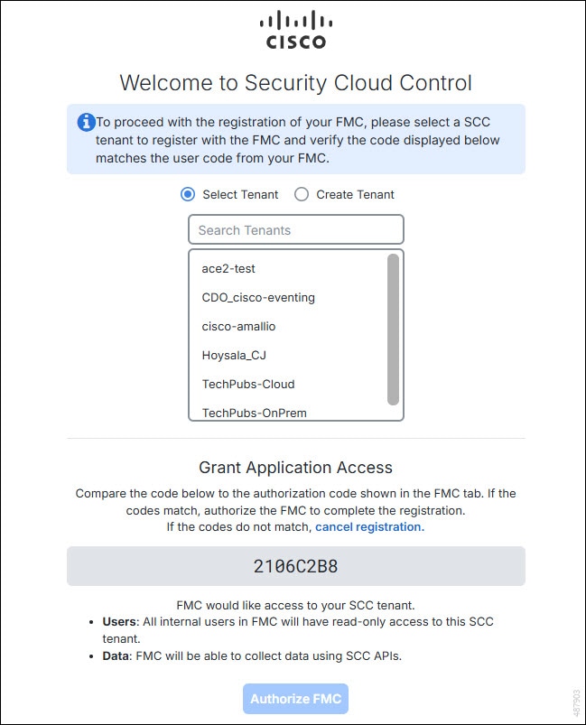
Figure 3. Choose the Security Cloud Control Tenant
A screen capture of Security Cloud Control page for selecting the Security Cloud Control tenant to which the management center can be associated.

If you do not already have a Security Cloud Control tenant or if you want to use a new tenant for this integration, create a new tenant. Refer to Request a Security Cloud Control Tenant for more information.

Step 7

Verify that the code displayed in the Security Cloud Control login page matches the code provided by the Secure Firewall Management Center.
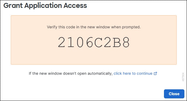
Figure 4. Verification Code in Firewall Management Center
A screen capture of the verification code displayed in management center.

Step 8

Click Authorize FMC.

Step 9

In the Secure Firewall Management Center, configure these settings:


After you complete this task, your management center and its managed devices are onboarded to the CDO tenant and integrated with Cisco Security Cloud. You can now manage devices, forward events, and use advanced Cisco security features from the cloud.

Configure Firewall Management Center to share usage metrics and statistics with Cisco

Configure Cisco Success Network to allow your Firewall Management Center to establish a secure connection to Cisco cloud and stream usage information and statistics. Cisco can then inform you about available features that you have not used, provide additional support services, and improve its products.

Cisco Success Network is a cloud service that enables the Firewall Management Center to establish a secure connection to Cisco cloud and stream usage information and statistics. Streaming telemetry enables you to select data of interest from the Firewall Threat Defense device. The device sends this data in a structured format to remote management stations. This transfer supports several purposes:

  • To inform you of available, but unused features that can improve the effectiveness of the product in your network.

  • To inform you of additional technical support services and monitoring that are available for your product.

  • To help Cisco improve its products.

To know more about the telemetry data that Cisco collects, refer to Cisco Success Network Telemetry Data Collected from Cisco Secure Firewall Management Center Devices.

The Firewall Management Center establishes and maintains a secure connection with Cisco cloud at all times when either Cisco Support Diagnostics or Cisco Success Network is enabled. However, the Firewall Management Center and the Firewall Threat Defense devices establish and maintain secure connections with the Cisco cloud when Cisco Support Diagnostics is enabled. You can turn off this connection at any time by disabling both Cisco Success Network and Cisco Support Diagnostics, which disconnects the Firewall Management Center from the Cisco cloud.

You can enable Cisco Success Network when you register the Firewall Management Center with the Smart Software Manager.


Note


  • Cisco Success Network is not supported in evaluation mode.

  • Cisco Success Network is not supported if the Firewall Management Center uses a valid Smart Software Manager On-Prem (formerly known as Smart Software Satellite Server) configuration or the Specific License Reservation.


Before you begin

Enable SecureX integration or register your Firewall Management Center with the Smart License to perform this task.

Follow these steps to configure your Firewall Management Center to share usage metrics and statistics with Cisco.

Procedure


Step 1

Click Integration > SecureX.

Step 2

Under Cisco Cloud Support, check the Enable Cisco Success Network check box to enable this service.

Note

 
Read the information provided next to the Enable Cisco Success Network check box before you proceed.

Step 3

Click Save.


After completing these steps, your Firewall Management Center will securely share usage metrics and statistics with Cisco, enabling enhanced support and product improvement.

Configure Firewall Management Center to share device health data with Cisco

Configure Firewall Management Center to enable sharing of configuration and operational health data with Cisco. This capability allows automated problem detection and supports TAC assistance. You can automate sending device health data to Cisco for analysis and proactive issue notification.

Cisco Support Diagnostics sends configuration and operational health data to Cisco, and processes that data through our automated problem detection system. This feature also allows Cisco TAC to collect essential information from your devices during the course of a case. For users with specific service contracts, we can proactively notify you of issues.

Both the Firewall Management Center and its devices communicate with Cisco. For more information, refer to Internet Resources Accessed. This feature is available in version 7.2 and later.

Before you begin

  • Enable SecureX integration or register with the Smart Software Manager.

  • Verify that your system meets the integration or registration requirements before proceeding.

Follow these steps to configure Firewall Management Center to share device health data with Cisco.

Procedure


Step 1

Choose Integration > SecureX.

Step 2

Under Cisco Cloud Support, check the Enable Cisco Support Diagnostics.

Note


Read the information provided next to the Enable Cisco Support Diagnostics check box before you proceed.

Step 3

Click Save.


After you complete this task, Firewall Management Center will send configuration and operational health data to Cisco, enabling automated diagnostics and proactive support notifications.

Meet requirements and prerequisites for the system configuration

This reference lists the requirements and prerequisites for the system configuration, including supported models, domains, and user roles.

Model support

Firewall Management Center

Supported domains

Global

User roles

Admin

Manage the Secure Firewall Management Center system configuration

Configure the system to establish and maintain the essential settings for the Secure Firewall Management Center. Ensure that these settings align with organizational requirements.

The system configuration identifies basic settings for the Firewall Management Center. Use this task when you need to review or update the fundamental configuration options for the management center.

Before you begin

Access to the Secure Firewall Management Center interface may be required. Follow these steps to manage the Secure Firewall Management Center system configuration.

Procedure


Step 1

Choose System (system gear icon) > Configuration.

Step 2

Use the navigation panel to choose configurations to change.


When you complete the steps, the basic settings for the Secure Firewall Management Center will update to maintain proper system operation.

What to do next

Verify that the configuration changes are applied and the system is functioning as expected.

Access lists

An access list is a security configuration that

  • limits access to the Firewall Management Center by IP address and port

  • enables default ports for any IP address, and

  • allows optional access for SNMP polling after SNMP is enabled.

Default and optional port access

You can limit access to the Firewall Management Center by IP address and port. These ports are enabled by default for any IP address:

  • Port 443 (HTTPS) for web interface access.

  • Port 22 (SSH) for CLI access.

You can also add access to poll for SNMP information over port 161. Because SNMP is disabled by default, enable SNMP before adding SNMP access rules. For more information, refer to Configure SNMP polling.


Caution


By default, access is not restricted. To operate in a more secure environment, consider adding access for specific IP addresses and then deleting the default any option.


Configure an access list

To enable secure management of your device, specify which IP addresses can connect and choose the protocols (SSH, HTTPS, or SNMP) they are permitted to use.

This access list does not control external database access. For more information, refer to Enable external access to the database.

If you remove access for the IP address you are using and there is no rule for "IP=any port=443", you will lose your connection when you save the configuration.

Before you begin

By default, the access list includes rules for HTTPS and SSH. To add SNMP rules to the access list, you must first enable SNMP. For more information, refer to Configure SNMP polling.

Procedure


Step 1

Choose System (system gear icon) > Configuration.

Step 2

(Optional) Click SNMP to configure SNMP if you want to add SNMP rules to the access list. By default, SNMP is disabled; refer to Configure SNMP polling.

Step 3

Click Access List.

Step 4

Click Add Rules to add access for IP addresses.

Step 5

In the IP Address field, enter an IP address or address range, or any.

Step 6

Choose SSH, HTTPS, SNMP, or a combination of these options to specify which ports you want to enable for these IP addresses.

Step 7

Click Add.

Step 8

Click Save.


The management center allows connections only from the IP addresses and protocols you specify.

Configure access control preferences

You can track changes to access control rules by allowing or requiring users to comment when they save. This allows you to assess why critical policies in a deployment were modified. By default, this feature is disabled.

Configure object optimization to evaluate and optimize network or host policy objects that are used in rules. The system then creates associated network object groups on the device. For more information, refer to Object-group optimization.

Procedure


Step 1

Choose System (system gear icon) > Configuration > Access Control Preferences.

Step 2

From the Comments on rule change list, choose an option:

  • Disabled: Disables comments for access control rule changes.

  • Optional: Allows users to optionally add a comment when they change an access control rule.

  • Required: Requires users to add a comment when they change an access control rule.

Step 3

From the Object-group optimization list, choose an option:

  • Enabled—Enables object-group optimization. The setting takes effect after deployment.

  • Disabled—Disables object-group optimization.

Warning

 
For the first deployment to a threat defense device after you enable object-group optimization, the device can take several minutes to an hour to reevaluate the policy configuration and optimize object groups. CPU utilization on the device can also increase. Schedule the deployment during a low-traffic period or a maintenance window.

Step 4

Click Save.


What to do next

Deploy the access control policies for object-group optimization to take effect.

Audit logs

An audit log is a security record that

  • records user activity in read-only logs,

  • allows review, sorting, filtering, deletion, and reporting of audit information, and

  • supports streaming audit log messages to external servers such as syslog and HTTP servers.

Audit log review and streaming options

You can review audit log data in several ways:

  • Use the web interface: Audit and Syslog.

    Audit logs appear in a standard event view. In this view, you can view, sort, and filter audit log messages based on any item. You can also delete audit information, generate reports, and view detailed reports of user changes.

  • Stream audit log messages to the syslog: Stream audit logs to syslog.

  • Stream audit log messages to an HTTP server: Stream audit logs to an HTTP server.

Streaming audit log data to an external server allows you to conserve space on the Firewall Management Center. Note that sending audit information to an external URL may affect system performance.

Optionally, you can secure the channel for audit log streaming, enable TLS and mutual authentication using TLS certificates; refer to Audit log certificates.

Streaming to multiple syslog servers

You can stream audit log data to a maximum of five syslog servers. However, if you have enabled TLS for secured audit log streaming, you can stream only to a single syslog server.

Stream audit logs to syslog

Configure audit log streaming to syslog servers to ensure centralized monitoring and compliance tracking for your system. Enable external logging of configuration changes and security events.

When this feature is enabled, audit log records appear in the syslog in the following format:

Date Time Host: [Tag] Sender: User_Name@User_IP, Subsystem, Action

Where the local date, time, and originating hostname precede the bracketed optional tag, and the sending device name precedes the audit log message.

For example, if you specify a tag of FMC-AUDIT-LOG for audit log messages from your management center, a sample audit log message from your Firewall Management Center could appear as follows:

Mar 01 14:45:24 localhost: [FMC-AUDIT-LOG] Dev-MC7000: admin@10.1.1.2, Operations > Monitoring, Page View

If you specify a severity and facility, these values do not appear in syslog messages; instead, they tell the system that receives the syslog messages how to categorize them.

This task is relevant when you need to send audit logs from your management center to an external syslog server for compliance or operational monitoring. Use this procedure when integrating with centralized log management solutions.

Before you begin

Make sure the Firewall Management Center can communicate with the syslog server. When you save your configuration, the system uses ICMP/ARP and TCP SYN packets to verify syslog server connectivity. By default, the system uses port 514/UDP to stream audit logs. To secure the channel (optional, refer to Audit log certificates), manually configure port 1470 for TCP.

Follow these steps to stream audit logs to a syslog server:

Procedure


Step 1

Choose System (system gear icon) > Configuration.

Step 2

Click Audit Log.

Step 3

Choose Enabled from the Send Audit Log to Syslog drop-down menu.

Step 4

The following fields are applicable only for audit logs sent to syslog:

Option

Description

Host

The IP address or the fully qualified name of the syslog server to which you will send audit logs. You can add a maximum of five syslog hosts, separated by commas.

Note


You can specify multiple syslog hosts, only when TLS is disabled for the Audit Server Certificate.

Facility

The subsystem that creates the message.

Choose a facility described in SYSLOG alert facilities. For example, choose AUDIT.

Severity

The severity of the message.

Choose a severity described in Syslog severity levels.

Tag

An optional tag to include in audit log syslog messages.

Best practice: Enter a value in this field to easily differentiate audit log messages from other, similar syslog messages such as health alerts.

For example, if you want all audit log records sent to the syslog to be labeled with FMC-AUDIT-LOG, enter FMC-AUDIT-LOG in the field.

Step 5

(Optional) To test whether the IP address of the syslog servers is valid, click Test Syslog Server.

The system sends the following packets to verify whether the syslog server is reachable:

  1. ICMP echo request

  2. TCP SYN on 443 and 80 ports

  3. ICMP time stamp query

  4. TCP SYN on random ports

Note


If the Firewall Management Center and syslog server are in the same subnet, ARP is used instead of ICMP.

The system displays the result for each server.

Step 6

Click Save.


After you complete this task, audit logs are sent from the management center to the specified syslog server, allowing you to monitor and review system activity externally.

What to do next

Verify that the syslog server is receiving audit log messages as expected. Check for log entries corresponding to configuration changes or security events.

Stream audit logs to an HTTP server

Stream audit logs from the device to an HTTP server to centralize log management and support compliance requirements.

Use this task to forward audit logs from your device to an external HTTP server for monitoring, analysis, or compliance.

When this feature is enabled, the appliance sends audit log records to an HTTP server in the following format:

Date Time Host: [Tag] Sender: User_Name@User_IP, Subsystem, Action

Where the local date, time, and originating hostname precede the bracketed optional tag, and the sending appliance name precedes the audit log message.

For example, if you specify a tag of FROMMC, a sample audit log message could appear as follows:

Mar 01 14:45:24 localhost: [FROMMC] Dev-MC7000: admin@10.1.1.2, Operations > Monitoring, Page View

Before you begin

Make sure the device can communicate with the HTTP server. Optionally, secure the channel. Refer to Audit log certificates.

Follow these steps to stream audit logs to an HTTP server.

Procedure


Step 1

Choose System (system gear icon) > Configuration.

Step 2

Click Audit Log.

Step 3

Optionally, in the Tag field, enter the tag name that you want to appear with the message. For example, if you want all audit log records to be preceded with FROMMC, enter FROMMC in the field.

Step 4

Choose Enabled from the Send Audit Log to HTTP Server drop-down list.

Step 5

In the URL to Post Audit field, designate the URL where you want to send the audit information. Enter a URL that corresponds to a Listener program that expects the HTTP POST variables as listed:

  • subsystem

  • actor

  • event_type

  • message

  • action_source_ip

  • action_destination_ip

  • result

  • time

  • tag (if defined; see Step 3)

Caution

 
To allow encrypted posts, use an HTTPS URL. Sending audit information to an external URL may affect system performance.

Step 6

Click Save.


When you complete this task, the device sends audit logs to the specified HTTP server. Centralized monitoring and record-keeping become possible.

Filter syslogs from audit logs

When you enable Send Audit Log to Syslog and provide Host information, syslog messages are also sent to the configured host in addition to the audit logs. This behavior occurs because the system creates /etc/syslog-ng.d/syslog-tls.conf when you deploy the Firepower platform settings policy. As a result, syslog messages are forwarded to the configured host rather than only sending the audit logs.

If your auditing policy does not need these syslog records, you can prevent syslogs from being streamed to the configured host. To filter syslogs from audit logs, ensure you have access to the appliance’s admin user account. You must also be able to access the appliance’s console or open a secure terminal.


Caution


Make sure that only authorized personnel have access to the appliance and to its admin account.


Procedure


Step 1

In the /etc/syslog-ng.conf file, comment out the @include "/etc/syslog-ng.d/*.conf" line.

Example:

#@include "/etc/syslog-ng.d/*.conf"

Step 2

Reload the syslog configuration file. Use the syslog-ng-ctl reload command to reload the configuration file without having to restart the application.

Example:

syslog-ng-ctl reload

Audit log certificates

An audit log certificate is a security credential that

  • secures communications between the Firewall Management Center and a trusted audit log server,

  • enables authentication and encryption using Transport Layer Security (TLS), and

  • supports mutual authentication and certificate revocation checks for enhanced security.

Client certificates

Client certificates are required to secure communications between the Firewall Management Center and the audit log server.

Server certificates

Server certificates are optional and provide additional security through mutual authentication.

  • Require mutual authentication between the Firewall Management Center and the audit log server by loading one or more certificate revocation lists (CRLs).

  • You cannot stream audit logs to servers with revoked certificates listed in those CRLs.

  • Secure Firewall supports CRLs encoded in Distinguished Encoding Rules (DER) format. These are the same CRLs used to validate HTTPS client certificates for the Firewall Management Center web interface.

  • Use the local system configuration: Require valid audit log server certificates.

Audit log certificate example

For example, a signed client certificate imported onto the Firewall Management Center enables secure TLS communication with an audit log server, ensuring log integrity and confidentiality.

Non-compliant audit log certificate

A certificate that is not signed by a trusted Certificate Authority or is listed in a certificate revocation list (CRL) cannot be used to stream audit logs securely.

Audit log certificate analogy

An audit log certificate is like a passport for secure communication, verifying identity and granting access between the management center and the audit log server.

Secure audit log streaming

Configure secure audit log streaming to ensure that audit logs are transmitted safely between the Firewall Management Center and a trusted server.

When you stream the audit log to a trusted HTTP server or syslog server, use Transport Layer Security (TLS) certificates to secure the channel between the Firewall Management Center and the server.

You must generate a unique client certificate for each appliance you want to audit. Mutual authentication requires the client certificate to be signed by the same CA as the server certificate. For more considerations on client and server certificate requirements, refer to Audit log certificates.

Before you begin

Refer to ramifications of requiring client and server certificates at Audit log certificates. Ensure you have access to a recognized certificate authority (CA) for signing client certificates.

Follow these steps to secure audit log streaming.

Procedure


Step 1

Obtain and install a signed client certificate on the Firewall Management Center.

  1. Obtain a signed audit log client certificate for the Firewall Management Center:

    Generate a Certificate Signing Request (CSR) from the Firewall Management Center based on your system information and the identification information you supply.

    • Submit the CSR to a recognized, trusted certificate authority (CA) to request a signed client certificate.

    • If you will require mutual authentication between the Firewall Management Center and the audit log server, ensure the client certificate is signed by the same CA that signed the server certificate.

  2. After you receive the signed certificate from the certificate authority, import it into the Firewall Management Center. Refer to Import an audit log client certificate into the Firewall Management Center.

Step 2

Configure the communication channel with the server to use Transport Layer Security (TLS) and enable mutual authentication.

Refer to Require valid audit log server certificates.

Step 3

If you have not yet configured audit log streaming, do so now.

Refer to Stream audit logs to syslog or Stream audit logs to an HTTP server.

Audit logs are securely streamed to the trusted server using TLS, with mutual authentication enabled. The Firewall Management Center and the server verify each other's certificates, ensuring secure transmission and integrity of audit log data.

What to do next

Monitor the audit log streaming status and verify certificate validity periodically. Renew client and server certificates before expiration to maintain secure log streaming.

Obtain a signed audit log client certificate for the Firewall Management Center

Obtain a signed audit log client certificate for the Firewall Management Center. This certificate enables secure communication between the appliance and the audit log server. It ensures that the server can authenticate audit log data and that the data is transmitted securely.

The system generates certificate request keys in Base-64 encoded PEM format.


Important


The Audit Log Certificate page is not available on a standby Firewall Management Center in a high availability setup. You cannot perform this task from a standby Firewall Management Center.


Perform this task on the active appliance to generate a certificate signing request for audit log client authentication. Do not perform this task on a standby appliance in a high availability setup.

Before you begin

Keep this in mind:

  • To ensure security, use a globally recognized and trusted certificate authority (CA) to sign your certificate.

  • If you will require mutual authentication between the appliance and the audit log server, the same certificate authority must sign both the client certificate and the server certificate.

Follow these steps to obtain a signed audit log client certificate for the Firewall Management Center:

Procedure


Step 1

Choose System (system gear icon) > Configuration and click Audit Log Certificate.

Step 2

Click Generate New CSR.

Step 3

Enter a country code in the Country Name (two-letter code) field.

Step 4

Enter a state or province postal abbreviation in the State or Province field.

Step 5

Enter a Locality or City, an Organization name, and an Organizational Unit (Department) name.

Step 6

Enter the fully qualified domain name of the server for which you want to request a certificate in the Common Name field.

Note


If the common name and the DNS hostname do not match, audit log streaming will fail.

Step 7

Click Generate and then open a new blank file with a text editor.

Step 8

Copy the block of text from the certificate request, including the BEGIN CERTIFICATE REQUEST and END CERTIFICATE REQUEST lines. Paste this information into a blank text file.

Step 9

Save the file as clientname.CSR. Replace clientname with the appliance name where you plan to use the certificate. Click Close.


After completing these steps, you will have a certificate signing request (CSR) file that can be submitted to a trusted certificate authority. After it is signed, you can import the certificate to the appliance for secure audit log streaming.

What to do next

Import an audit log client certificate into the Firewall Management Center

Importing an audit log client certificate enables secure communication between the Secure Firewall Management Center and external systems during audit log transmission. This task verifies that you import the correct signed certificate and any necessary intermediate certificates for secure operations.

In a Secure Firewall Management Center high availability setup, you must use the active peer when importing the audit log client certificate. This procedure is relevant when configuring audit log security or after obtaining a new signed client certificate.

Before you begin

Follow these steps to import an audit log client certificate into the Secure Firewall Management Center.

Procedure


Step 1

On the Firewall Management Center, choose System (system gear icon) > Configuration.

Step 2

Click Audit Log Certificate.

Step 3

Click Import Audit Client Certificate.

Step 4

Open the client certificate in a text editor, copy the entire block of text, including the BEGIN CERTIFICATE and END CERTIFICATE lines. Paste this text into the Client Certificate field.

Step 5

To upload a private key, open the private key file and copy the entire block of text, including the BEGIN RSA PRIVATE KEY and END RSA PRIVATE KEY lines. Paste this text into the PRIVATE KEY field.

Step 6

Open any required intermediate certificates, copy the entire block of text for each, and paste it into the Certificate Chain field.

Step 7

Click Save.


The audit log client certificate and any required intermediate certificates are successfully imported into the Secure Firewall Management Center.

Require valid audit log server certificates

The system supports validating audit log server certificates using imported CRLs in Distinguished Encoding Rules (DER) format.


Note


If you choose to verify certificates using CRLs, the system uses the same CRLs to validate both audit log server certificates and certificates used to secure the HTTP connection between an appliance and a web browser.


Important


You cannot perform this procedure on the standby Firewall Management Center in a high availability pair.


Before you begin

  • Understand the ramifications of requiring mutual authentication and of using certificate revocation lists (CRLs) to ensure that certificates are still valid. Refer to Audit log certificates.

  • Obtain and import the client certificate following the steps in Secure audit log streaming and the topics referenced in that procedure.

Procedure


Step 1

On the Firewall Management Center , choose System (system gear icon) > Configuration .

Step 2

Click Audit Log Certificate .

Step 3

To use Transport Layer Security to securely stream the audit log to an external server, select Enable TLS .

When TLS is enabled, the syslog client ( Firewall Management Center ) verifies the certificate received from the server. The connection between the client and the server succeeds only if server certificate verification is successful. For this verification process, these conditions must be met:

  • Configure the syslog server to send the certificate to the client.

  • Add (import) a CA certificate to the client to verify the server certificate:

    • You must import the CA certificate during the import of the client certificate.

    • If the issuing CA is a subordinate CA, add the issuing CA before adding the signing CA from the subordinate CA (Root CA).

Step 4

If you do not want the client to authenticate itself against the server, but wish to accept the server certificate when the certificate is issued by the same CA (not recommended), complete these steps.

  1. Deselect Enable Mutual Authentication .

    Important


    Ensure that the server is configured to trust the client without verifying any client certificates.

  2. Click Save and skip the remainder of this procedure.

Step 5

(Optional) To enable client certificate verification by the audit log server, select Enable Mutual Authentication.

Important


The Enable Mutual Authentication option is applicable only when TLS is enabled.

When mutual authentication is enabled, the syslog client ( Firewall Management Center ) sends a client certificate to the syslog server for verification. The client uses the same CA certificate of the CA who signed the server certificate of the syslog server. The connection succeeds only if client certificate verification is successful. For this verification process, these conditions must be met:

  • Configure the syslog server to verify the certificate received from the client.

  • Add a client certificate to be sent to the syslog server. This certificate must be signed by the same CA who signed the server certificate of the syslog server.

Note


To use mutual authentication for streaming Audit Log to the Syslog server, use PKCS#8 format for the private key instead of PKCS#1 format. Use this command line to convert PKCS#1 keys to PKCS#8 format:


							openssl pkcs8 -topk8 -inform PEM -outform PEM 
							-nocrypt -in 
							
								PKCS1 key file name
							 
							-out 
							
								PKCS8 key filename


Step 6

(Optional) To automatically recognize server certificates that are no longer valid:

  1. Select Enable Fetching of CRL .

    Important

     
    This option is displayed only when you select the Enable Mutual Authentication check box. However, the Enable Fetching of CRL option is applicable only when the TLS option is enabled. The use of CRL is for server certification verification, and it is not dependent on the use of Mutual Authentication which is for enabling client certificate verification.

    When you enable fetching of the CRL, the client creates a scheduled task to regularly update (download) the CRL or CRLs. The CRLs are used for server certificate verification. Verification fails if a CRL from the CA specifies that the server certificate has been revoked.

  2. Enter a valid URL to an existing CRL file and click Add CRL.

    Repeat to add up to 25 CRLs.

  3. Click Refresh CRL to load the current CRL or CRLs from the specified URL or URLs.

Step 7

Verify that you have a valid server certificate generated by the same certificate authority that created the client certificate.

Step 8

Click Save.


What to do next

(Optional) Set the frequency of CRL updates. .

View the audit log client certificate on the Firewall Management Center

View the audit log client certificate to confirm its presence and details on the appliance you are logged in to. This helps ensure that audit log operations are secured with the correct certificate.

You can view the audit log client certificate only for the appliance that you are logged in to.

In Firewall Management Center high availability pairs, you can view the certificate only on the active peer.

Before you begin

Follow these steps to view the audit log client certificate on the appliance:

Procedure


Step 1

Choose System (system gear icon) > Configuration.

Step 2

Click Audit Log Certificate.


The appliance you are logged in to displays the audit log client certificate details. For high availability pairs, only the active peer shows the certificate.

Change reconciliation

A change reconciliation report is a configuration monitoring tool that

  • captures snapshots whenever a user saves changes to the system configuration,

  • combines information from these snapshots to present a clear summary of recent system changes, and

  • provides a detailed report of changes made over the past 24 hours through email.

User change summaries

The change reconciliation report displays both the previous value for each configuration and the value after changes.

Users can view summaries of each distinct change in chronological order, beginning with the most recent.

  • Lists both previous and updated values for each configuration.

  • Summarizes multiple changes to the same configuration.

  • Orders changes chronologically, starting with the most recent.

Change reconciliation report example

An example change reconciliation report includes a User section that lists configuration changes, showing both the previous and updated values for each item.

Non-reconciled changes

Changes made without reconciliation are not summarized or tracked in a report, making it difficult to monitor user activity.

Change reconciliation as a transaction log

Change reconciliation is similar to a transaction log, where each modification is recorded and summarized for review.

Configure change reconciliation

Configure change reconciliation to enable the system to generate and send daily reports of configuration changes, supporting audit and compliance requirements. This helps administrators monitor and review all changes made to the system within a 24-hour period.

Use this task when you need to track and review configuration changes made to your system for security, compliance, or operational awareness.

Change reconciliation is especially useful in environments where multiple administrators make changes or where audit trails are required for regulatory purposes. Perform this configuration after setting up your email server to ensure reports are delivered successfully.

Before you begin

Configure an email server to receive emailed reports of changes made to the system over a 24-hour period; refer to Configure a mail relay host and notification address for more information.

Follow these steps to configure change reconciliation.

Procedure


Step 1

Choose System (system gear icon) > Configuration.

Step 2

Click Change Reconciliation.

Step 3

Check the Enable check box.

Step 4

Choose the time of day you want the system to send out the change reconciliation report from the Time to Run drop-down lists.

Step 5

Enter email addresses in the Email to field.

Tip


Once you have added email addresses, click Resend Last Report to send recipients another copy of the most recent change reconciliation report.

Step 6

If you want to include policy changes, check the Include Policy Configuration check box.

Step 7

If you want to include all changes over the past 24 hours, check the Show Full Change History check box.

Step 8

Click Save.


After you complete this task, the system will automatically generate and email daily reports of all configuration changes, allowing you to monitor and review system modifications for compliance and troubleshooting.

Change reconciliation options

The change reconciliation options control whether the system includes records of policy changes and the full change history in the change reconciliation report. These options determine the scope and detail of reported changes.

The Include Policy Configuration option controls whether the system includes records of policy changes in the change reconciliation report. It includes changes to access control, intrusion, system, health, and network discovery policies. If you do not select this option, the report will not show changes to any policies. This option is available only on Firewall Management Centers.

The Show Full Change History option controls whether the system includes records of all changes over the past 24 hours in the change reconciliation report. If you do not select this option, the report includes only a consolidated view of changes for each category.


Note


The change reconciliation report does not include changes to Firewall Threat Defense interfaces and routing settings.


DNS caches

A DNS cache is a network appliance feature that

  • enables automatic IP address resolution on event view pages,

  • stores previously resolved IP addresses to avoid additional lookups, and

  • reduces network traffic and improves page display speed when IP address resolution is enabled.

Configure DNS cache properties

Configure DNS cache properties to manage DNS resolution caching on your system. You can enable or disable DNS caching and set the cache timeout to optimize DNS lookup performance.

DNS resolution caching is a system-wide setting that allows the caching of previously resolved DNS lookups.

Before you begin

Follow these steps to configure DNS cache properties.

Procedure


Step 1

Choose System (system gear icon) > Configuration.

Step 2

Choose DNS Cache.

Step 3

From the DNS Resolution Caching drop-down list, choose one of these options:

  • Enabled—Enable caching.
  • Disabled—Disable caching.

Step 4

In the DNS Cache Timeout (in minutes) field, enter the number of minutes a DNS entry remains cached in memory before it is removed for inactivity.

The default setting is 300 minutes (five hours).

Step 5

Click Save.


After completing this task, DNS cache properties are updated according to your configuration. DNS lookups will be cached based on your configuration. Entries remain in cache for the specified timeout period.

Dashboards

A dashboard is a system interface that

  • provides at-a-glance views of current system status through widgets,

  • uses small, self-contained components to give insight into different aspects of the system, and

  • includes several predefined dashboard widgets.

Dashboard configuration options

You can configure the Firewall Management Center so that Custom Analysis widgets are enabled on the dashboard.

Enable custom analysis widgets for dashboards

Enable custom analysis widgets to provide users with the ability to create visual representations of events based on flexible, user-configurable queries.

Custom Analysis dashboard widgets are used to visually represent events according to user-defined queries, offering flexibility in monitoring and analyzing dashboard data.

Before you begin

Follow these steps to enable custom analysis widgets for dashboards.

Procedure


Step 1

Choose System (system gear icon) > Configuration.

Step 2

Click Dashboard.

Step 3

Check the Enable Custom Analysis Widgets check box to allow users to add Custom Analysis widgets to dashboards.

Step 4

Click Save.


Database

To manage disk space, the Firewall Management Center periodically prunes the oldest intrusion events, audit records, Security Intelligence data, and URL filtering data from the event database. For each event type, you can specify how many records the Firewall Management Center retains after pruning; never rely on the event database containing more records of any type than the retention limit configured for that type. To improve performance, tailor the event limits to the number of events you regularly work with. You can optionally choose to receive email notifications when pruning occurs. For some event types, you can disable storage.

To manually delete individual events, use the event viewer. (Note that in Versions 6.6.0+, you cannot manually delete connection or security Intelligence events in this way.) You can also manually purge the database; refer to Data Purge and Storage.

Configure database event limits

Configure database event limits to manage the number of records retained in each database and to receive notifications when data pruning occurs. This helps maintain optimal database performance and ensures you are informed about important data retention events.

This task is relevant when you need to control database size and receive alerts about event pruning in the Secure Firewall Management Center.

Use this procedure as part of regular database maintenance or when adjusting event retention policies. This configuration ensures that your system retains only the necessary amount of event data and notifies you when records are pruned.

Before you begin

If you want to receive email notifications when events are pruned from the Firewall Management Center's database, you must configure an email server; refer to Configure a mail relay host and notification address.

Follow these steps to configure database event limits and set up pruning notifications:

Procedure


Step 1

Choose System (system gear icon) > Configuration.

Step 2

Choose Database.

Step 3

Enter the number of records to store for each database.

For information on how many records each database can maintain, refer to Database event limits.

Step 4

Optionally, in the Data Pruning Notification Address field, enter the email address where you want to receive pruning notifications.

Step 5

Click Save.


After completing this task, the database will store only the specified number of records for each database, and you will receive email notifications if data pruning occurs (if configured).

Database event limits

This table lists the minimum and maximum number of records for each event type that you can store per Firewall Management Center .

Table 1. Database Event Limits

Event Type

Upper Limit

Lower Limit

Intrusion events

10 million ( Firewall Management Center Virtual)


30 million ( Firewall Management Center 1000, Firewall Management Center 1600, )

60 million ( Firewall Management Center 2500, Firewall Management Center 2600, , FMCv 300)

300 million ( Firewall Management Center 4500, Firewall Management Center 4600 )

10,000

Discovery events

10 million
 ( Firewall Management Center Virtual)

20 million ( Firewall Management Center 2500, Firewall Management Center 2600, Firewall Management Center 4500, Firewall Management Center 4600, FMCv 300)

Zero (disables storage)

Connection events

Security Intelligence events

50 million ( Firewall Management Center Virtual )


100 million ( Firewall Management Center 1000, Firewall Management Center 1600, )


300 million ( Firewall Management Center 2500, Firewall Management Center 2600, , FMCv 300)


1 billion ( Firewall Management Center 4500, Firewall Management Center 4600 )

Limit is shared between connection events and security intelligence events . The sum of the configured maximums cannot exceed this limit.

Zero (disables storage)

If you set the Maximum Connection Events value to zero, then connection events that are not associated with security intelligence , intrusion, file, and malware events are not stored on the Firewall Management Center .

Caution


Setting Maximum Connection Events to zero immediately purges existing connection events other than security intelligence events .

This setting affects the Maximum Flow Rate, as described in the next section.

These settings do not affect connection summaries.

Connection summaries (aggregated connection events)

50 million ( Firewall Management Center Virtual )

100 million ( Firewall Management Center 1000, Firewall Management Center 1600, )


300 million ( Firewall Management Center 2500, Firewall Management Center 2600, , FMCv 300)

1 billion ( Firewall Management Center 4500, Firewall Management Center 4600 )

Zero (disables storage)

Correlation events and compliance allow list events

1 million
 ( Firewall Management Center Virtual)


2 million ( Firewall Management Center 2500, Firewall Management Center 2600, Firewall Management Center 4500, Firewall Management Center 4600, FMCv 300)

One

Malware events

10 million
( Firewall Management Center Virtual, Firewall Management Center 1600, )

20 million ( Firewall Management Center 2500, Firewall Management Center 2600, Firewall Management Center 4500, Firewall Management Center 4600, FMCv 300)

10,000

File events

10 million
 ( Firewall Management Center Virtual, Firewall Management Center 1600)


20 million ( Firewall Management Center 2500, Firewall Management Center 2600, , Firewall Management Center 4500, Firewall Management Center 4600, FMCv 300)

Zero (disables storage)

Health events

1 million

Zero (disables storage)

Audit records

100,000

One

Remediation status events

10 million

One

Allow list violation history

a 30-day history of violations

One day’s history

User activity (user events)

10 million

One

User logins (user history)

10 million

One

Intrusion rule update import log records

1 million

One

VPN Troubleshooting database

10 million

Zero (disables storage)

Maximum Flow Rate

The Maximum flow rate (flows per second) value for your Firewall Management Center hardware model is specified in the Platform Specifications section of the Firewall Management Center datasheet at https://www.cisco.com/c/en/us/products/collateral/security/firesight-management-center/datasheet-c78-736775.html?cachemode=refresh

If you set the Maximum Connection Events value in platform settings to zero, then connection events that are not associated with security intelligence events , intrusion, file, and malware events are not counted toward the maximum flow rate for your Firewall Management Center hardware.

Any non-zero value in this field causes ALL connection events to be counted against the maximum flow rate.

Other event types on this page do not count against the maximum flow rate.

Email notifications

An email notification is a system alert mechanism that enables automated emailing of event-based, status, change reconciliation, and data-pruning reports.

Email notification configuration options

Configure a mail host if you plan to:

  • Email event-based reports

  • Email status reports for scheduled tasks

  • Email change reconciliation reports

  • Email data-pruning notifications

  • Use email for discovery event, impact flag, correlation event alerting, intrusion event alerting, and health event alerting.

When you configure email notification, you can select an encryption method for the communication between the system and mail relay host, and can supply authentication credentials for the mail server if needed. After you configure email notification, you can test the connection.

Configure a mail relay host and notification address

Email notifications help administrators track important events and maintain appliance security. Configuring your appliance to use a relay mail server ensures that messages are sent securely.

Procedure


Step 1

Choose System (system gear icon) > Configuration.

Step 2

Click Email Notification.

Step 3

In the Mail Relay Host field, enter the hostname or IP address of the mail server you want to use. Ensure the mail host you enter allows access from the appliance.

Step 4

In the Port Number field, enter the port number to use on the email server.

Typical ports include:

  • 25, when using no encryption

  • 465, when using SSLv3

  • 587, when using TLS

Step 5

Choose an Encryption Method:

  • TLS: Encrypt communications using Transport Layer Security.
  • SSLv3: Encrypt communications using Secure Socket Layers.
  • None: Allow unencrypted communication.

Note


Certificate validation is not required for encrypted communication between the appliance and mail server.

Step 6

In the From Address field, enter the valid email address you want to use as the source email address for messages sent by the appliance.

Step 7

To supply a username and password when connecting to the mail server, choose Use Authentication. Enter the username in the Username field. Enter a password in the Password field.

Step 8

To send a test email using the configured mail server, click Test Mail Server Settings.

A message appears next to the button indicating the success or failure of the test.

Step 9

Click Save.


External database access

An external database access is a database connectivity feature that

  • allows read-only access to the database by third-party clients,

  • enables querying the database using SQL with industry-standard reporting tools and applications, and

  • supports secure connections through JDBC SSL and provides Cisco-provided tools for database access.

Database access tools and configuration

You can configure the Firewall Management Center to allow read-only access to its database by a third-party client. This allows you to query the database using SQL with these tools and applications:

  • industry-standard reporting tools such as Actuate BIRT, JasperSoft iReport, or Crystal Reports,

  • any other reporting application (including a custom application) that supports JDBC SSL connections,

  • the Cisco-provided command-line Java application called RunQuery, which you can either run interactively or use to obtain comma-separated results for a single query.

Use the Firewall Management Center's system configuration to enable database access and create an access list so selected hosts can query the database. This access list does not control appliance access.

You can also download a package that contains these tools:

  • RunQuery, the Cisco-provided database query tool,

  • InstallCert, a tool that you can use to retrieve and accept the SSL certificate from the Firewall Management Center that you want to access,

  • the JDBC driver you must use to connect to the database.

Refer to the Secure Firewall Management Center Database Access Guide for information on using the tools in the package you downloaded to configure database access.

Enable external access to the database

Enable external access to the database so that third-party applications and remote hosts can connect as required.

Perform this configuration when integrating with third-party tools or enabling remote database access for operational needs. Ensure you understand your organization's security requirements before enabling external access.

Before you begin

Verify that you have administrative access and know the required hostnames or IP addresses for external access.

Follow these steps to enable external access to the database.

Procedure


Step 1

Choose System (system gear icon) > Configuration.

Step 2

Click External Database Access.

Step 3

Select the Allow External Database Access check box.

Step 4

Enter an appropriate value in the Server Hostname field. Depending on your third-party application requirements, this value can be either the fully qualified domain name (FQDN), IPv4 address, or IPv6 address of the Firewall Management Center.

Note


In Firewall Management Center high availability setups, enter only the active peer details. We do not recommend entering details of the standby peer.

Step 5

Next to Client JDBC Driver, click Download and follow your browser’s prompts to download the client.zip package.

Step 6

To add database access for one or more IP addresses, click Add Hosts. An IP Address field appears in the Access List field.

Step 7

In the IP Address field, enter an IP address or address range, or any.

Step 8

Click Add.

Step 9

Click Save.

Tip


If you want to revert to the last saved database settings, click Refresh.


External access to the database is enabled. Specified hosts can now connect using the configured settings, and the JDBC driver is available for client applications.

What to do next

Review database access logs to monitor external connections and ensure compliance with security policies. Update access lists when you need to add or remove hosts.

HTTPS certificates

An HTTPS certificate is a security credential that

  • enables Firewall Management Centers to establish an encrypted channel between the system and a web browser

  • includes a default certificate with all firewall devices, and

  • may require replacement with a custom certificate signed by a globally recognized or internally trusted certificate authority to improve trust.

Certificate support information

The Firewall Management Center supports 4096-bit HTTPS certificates. If the certificate used by the Firewall Management Center was generated using a public server key larger than 4096 bits, you will not be able to log in to the Firewall Management Center web interface. If this happens, contact Cisco TAC.


Note


HTTPS certificates are not supported on the management center REST API.


Default HTTPS server certificates

A default HTTPS server certificate is a security credential that

  • is provided with an appliance for web interface access,

  • is not signed by the CA that signs client certificates, and

  • expires 20 years from when it was first generated.

Default HTTPS server certificate reference information

Default HTTPS server certificates have specific characteristics and limitations.

  • If you use the default server certificate provided with an appliance, do not configure the system to require a valid HTTPS client certificate for web interface access. The default server certificate is not signed by the CA that signs your client certificate.

  • The default server certificate provided with an appliance expires 20 years from when it was first generated.

  • The lifetime of the default server certificate depends on when the certificate was generated. To view your default server certificate expiration date, choose System (system gear icon) > Configuration > HTTPS Certificate.

  • Some Secure Firewall software upgrades can automatically renew the certificate. For more information, refer to the appropriate version of the Cisco Secure FirewallRelease Notes.

  • On the Firewall Management Center, you can renew the default certificate on the System (system gear icon) > Configuration > HTTPS Certificate page.

Custom HTTPS server certificates

A custom HTTPS server certificate is a security credential that

  • is generated based on system and identification information you supply,

  • can be signed by an internal certificate authority (CA) trusted by your browser, and

  • can be imported after being signed by a certificate authority.

Meet HTTPS server certificate requirements

To secure the connection between your web browser and the Secure Firewall appliance web interface using HTTPS, you must use server certificates that comply with the Internet X.509 Public Key Infrastructure Certificate and Certificate Revocation List (CRL) Profile (RFC 5280). The system rejects certificates that are not compliant with X.509 version 3 of that standard.

Import an HTTPS server certificate only if it includes all required fields.

Certificate Field

Description

Version

Version of the encoded certificate. Use version 3. Refer to RFC 5280, section 4.1.2.1.

Serial number

A positive integer assigned to the certificate by the issuing CA. Issuer and serial number together uniquely identify the certificate. Refer to RFC 5280, section 4.1.2.2.

Signature

Identifier for the algorithm used by the CA to sign the certificate. Must match the signatureAlgorithm field. Refer to RFC 5280, section 4.1.2.3.

Issuer

Identifies the entity that signed and issued the certificate. Refer to RFC 5280, section 4.1.2.4.

Validity

Interval during which the CA warrants that it will maintain information about the status of the certificate. Refer to RFC 5280, section 4.1.2.5.

Subject

Identifies the entity associated with the public key stored in the subject public key field; must be an X.500 distinguished name (DN). Refer to RFC 5280, section 4.1.2.6.

Subject Alternative Name

The certificate secures domain names and IP addresses. Subject Alternative Name is defined in RFC 5280, section 4.2.1.6.

We recommend using this field if the certificate is used for multiple domains or IP addresses.

Subject Public Key Info

Public key and an identifier for its algorithm. Refer to RFC 5280, section 4.1.2.7.

Authority Key Identifier

Provides a means of identifying the public key corresponding to the private key used to sign a certificate. Refer to RFC 5280, section 4.2.1.1.

Subject Key Identifier

Provides a means of identifying certificates that contain a particular public key. Refer to RFC 5280, section 4.2.1.2.

Key Usage

Defines the purpose of the key contained in the certificates. Refer to RFC 5280, section 4.2.1.3.

Basic Constraints

Identifies whether the certificate Subject is a CA, and the maximum depth of validation certification paths that include this certificate. Refer to RFC 5280, section 4.2.1.9. For server certificates used in Secure Firewall appliances, use critical CA:FALSE.

Extended Key Usage extension

Indicates one or more purposes for which the certified public key may be used, in addition to or in place of the basic purposes indicated in the Key Usage extension. Refer to RFC 5280, section 4.2.1.12. Make sure to import certificates that can be used as server certificates.

signatureAlgorithm

Identifier for the algorithm the CA used to sign the certificate. Must match the Signature field. Refer to RFC 5280, section 4.1.1.2.

signatureValue

Digital signature. Refer to RFC 5280, section 4.1.1.3.

HTTPS client certificates

An HTTPS client certificate is a security credential that

  • enables the web server to check that a user’s browser client has a valid certificate selected,

  • requires the certificate to be generated by the same trusted certificate authority as the server certificate, and

  • prevents the browser from loading the web interface if the certificate is invalid or revoked.

Certificate validation methods

HTTPS client certificates are validated using OCSP or certificate revocation lists (CRLs).

  • OCSP allows the web server to communicate with the certificate authority to confirm the client certificate's validity before establishing the connection.

  • CRLs enable the web server to compare the client certificate against certificates listed in the CRLs. The system blocks access if the certificate is revoked.


Note


If you choose to verify certificates using CRLs, the system uses the same CRLs to validate both client browser certificates and audit log server certificates.


Invalid certificate scenarios

The browser cannot load the web interface if the user selects a certificate that is not valid, not generated by the certificate authority that signed the server certificate, or not generated by a certificate authority in the certificate chain on the device.

Certificates not accepted by the web server

If a user selects a certificate listed in a CRL as revoked, the browser cannot load the web interface.

Certificate validation compared to ID checks

Validating HTTPS client certificates is similar to checking a person's ID against a trusted list to ensure authenticity and prevent access if the ID is invalid or revoked.

View the current HTTPS server certificate

This task enables you to verify the HTTPS server certificate currently in use on your appliance. This process helps ensure secure communications by allowing you to review certificate details.

You can only view server certificates for the appliance you are logged in to. This task is relevant when you need to confirm the certificate used for HTTPS connections on your device.

Before you begin

Access to the appliance interface is necessary. Follow these steps to view the current HTTPS server certificate.

Procedure


Step 1

Choose System (system gear icon) > Configuration.

Step 2

Click HTTPS Certificate.


After completing these steps, the current HTTPS server certificate details for the appliance are displayed, allowing you to verify secure communication settings.

What to do next

Review certificate information when necessary for compliance or troubleshooting.

Generate an HTTPS server certificate signing request

Configure an HTTPS server certificate signing request (CSR) to enable secure communication between the appliance and client browsers. This task helps you generate a unique CSR for your device, which is required to obtain a signed certificate from a certificate authority.

f you install a certificate that is not signed by a globally recognized or internally trusted certificate authority, the browser displays a security warning when you attempt to connect to the web interface.

A certificate signing request (CSR) is unique to the appliance or device from which you generated it. You cannot generate a CSR for multiple devices from a single appliance. All fields are optional. However, we recommend that you enter values for CN, Organization, Organization Unit, City/Locality, State/Province, Country/Region, and Subject Alternative Name.

The key generated for the certificate request is in Base-64 encoded PEM format.

Before you begin

Follow these steps to generate an HTTPS server certificate signing request:

Procedure


Step 1

Choose System (system gear icon) > Configuration and click HTTPS Certificate.

Step 2

Click Generate New CSR.

This figure shows an example.

Step 3

Enter a country code in the Country Name (two-letter code) field and a state or province postal abbreviation in the State or Province field.

Step 4

Enter a Locality or City, Organization name, and an Organizational Unit (Department) name.

Step 5

Enter the fully qualified domain name of the server for which you want to request a certificate in the Common Name field.

Note


Enter the fully qualified domain name of the server exactly as it should appear in the certificate in the Common Name field. If the common name and the DNS hostname do not match, you receive a warning when connecting to the appliance.

Step 6

To request a certificate that secures multiple domain names or IP addresses, enter this information in the Subject Alternative Name section:

  1. Domain Names: Enter the fully qualified domains and subdomains (if any) secured by the Subject Alternative Name.

  2. IP Addresses: Enter the IP addresses secured by the Subject Alternative Name.

Step 7

Click Generate. Then, open a text editor.

Step 8

Copy the entire block of text in the certificate request, including the BEGIN CERTIFICATE REQUEST and END CERTIFICATE REQUEST lines. Paste it into a blank text file.

Step 9

Save the file as servername.CSR, where servername is the name of the server where you plan to use the certificate. Click Close.


After completing this task, you will have a Base-64 encoded PEM format certificate signing request file that you can submit to a certificate authority for signing.

What to do next

  • Submit the certificate request to the certificate authority.

  • When you receive the signed certificate, import it to the Firewall Management Center; refer to Import HTTPS server certificates.

Import HTTPS server certificates

Importing HTTPS server certificates enables secure communication between users and the appliance web interface by ensuring that the server presents a trusted certificate.

If the signing authority that generated the certificate requires you to trust an intermediate CA, you must also supply a certificate chain (or certificate path).

If you require client certificates, accessing an appliance via the web interface will fail when the server certificate does not meet either of these criteria:

  • The certificate is signed by the same CA that signed the client certificate.

  • The certificate is signed by a CA that has signed an intermediate certificate in the certificate chain.


Caution


The Firewall Management Center supports 4096-bit HTTPS certificates. If the certificate used by the Firewall Management Center was generated using a public server key larger than 4096 bits, you will not be able to log in to the Secure Firewall Management Center web interface. For more information about updating HTTPS Certificates to Version 6.0.0, refer to "Update Management Center HTTPS Certificates to Version 6.0" in Firepower System Release Notes, Version 6.0. If you generate or import an HTTPS CERTIFICATE and cannot log in to the Firewall Management Center web interface, contact support.


Before you begin

Follow these steps to import HTTPS server certificates.

Procedure


Step 1

Choose System (system gear icon) > Configuration.

Step 2

Click HTTPS CERTIFICATE.

Step 3

Click Import HTTPS Server Certificate.

Note


You cannot import an encrypted HTTPS certificate.

Step 4

Open the server certificate in a text editor, copy the entire block of text, including the BEGIN CERTIFICATE and END CERTIFICATE lines. Paste this text into the Server CERTIFICATE field.

Step 5

Whether you must supply a PRIVATE KEY depends on how you generated the certificate Signing Request:

  • If you generated the certificate Signing Request using the Secure Firewall Management Center web interface (as described in Generate an HTTPS server certificate signing request), the system already has the PRIVATE KEY and you need not enter one here.
  • If you generated the certificate Signing Request using some other means, you must supply the private key here. Open the private key file and copy the entire block of text, include the BEGIN RSA PRIVATE KEY and END RSA PRIVATE KEY lines. Paste this text into the Private Key field.

Step 6

Open each required intermediate certificate, copy the entire block of text, and paste it into the Certificate Chain field. If you have a root certificate, paste it into the same field. For all certificates, copy the entire block of text, including the BEGIN CERTIFICATE and END CERTIFICATE lines.

Step 7

Click Save.


After completing these steps, the HTTPS server certificate is imported and the appliance web interface can be accessed securely using the new certificate.

Require valid HTTPS client certificates

This task configures the system to require users connecting to the web interface to present a valid HTTPS client certificate, enhancing authentication security. Ensure only authorized users with valid certificates can access the web interface.

Use this procedure to require users connecting to the Firewall Management Center web interface to supply a user certificate. The system supports validating HTTPS client certificates using either OCSP or imported CRLs in Privacy-enhanced Electronic Mail (PEM) format.

If you choose to use CRLS, create a scheduled task to ensure that the list of revoked certificates stays current. The system displays the most recent refresh of the CRLS. To access the web interface after enabling client certificates, you must have a valid client certificate present in your browser (or a CAC inserted in your reader).


Note


To access the web interface after enabling client certificates, you must have a valid client certificate present in your browser (or a CAC inserted in your reader).


Before you begin

Follow these steps to require valid HTTPS client certificates.

Procedure


Step 1

Choose System (system gear icon) > Configuration.

Step 2

Click HTTPS Certificate.

Step 3

Choose Enable Client Certificates. If prompted, select the appropriate certificate from the drop-down list.

Step 4

You have three options:

  • To verify client certificates using one or more CRLS, select Enable Fetching of CRL and continue with Step 5.
  • To verify client certificates using OCSP, select Enable OCSP and skip to Step 7.
  • To accept client certificates without checking for revocation, skip to Step 8.

Step 5

Enter a valid URL to an existing CRL file and click Add CRL. Repeat this step to add up to 25 CRLs.

Step 6

Click Refresh CRL to load the current CRL or CRLS from the specified URLs.

Note


Enabling fetching of the CRL creates a scheduled task to regularly update the CRL or CRLS. Edit the task to set the frequency of the update.

Step 7

Verify that the client certificate is signed by the certificate authority loaded onto the appliance and the server certificate is signed by a certificate authority loaded in the browser certificate store. (These should be the same certificate authority.)

Caution


Saving a configuration with enabled client certificates, with no valid client certificate in your browser certificate store, disables all web server access to the appliance. Make sure that you have a valid client certificate installed before saving settings.

Step 8

Click Save.


After completing this task, only users with valid HTTPS client certificates will be able to access the web interface, and certificate validation will be enforced according to your configuration.

Renew the default HTTPS server certificate

Renewing the default HTTPS server certificate updates the certificate used for secure communications on the appliance. This task helps maintain security by ensuring the certificate is current and valid.

You can only view and renew server certificates for the appliance you are logged in to. This procedure is relevant when the system is configured to use the default HTTPS server certificate. The renewal option appears only if the default certificate is in use.

Before you begin

Ensure you are logged in to the appliance whose certificate you wish to renew. System must be configured to use the default HTTPS server certificate.

Follow these steps to renew the default HTTPS server certificate:

Procedure


Step 1

Choose System (system gear icon) > Configuration.

Step 2

Click HTTPS Certificate.

The button appears only if your system is configured to use the default HTTPS server certificate.

Step 3

Click Renew HTTPS Certificate. (This option appears on the display under the certificate information only if your system is configured to use the default HTTPS server certificate.)

Step 4

(Optional) In the Renew HTTPS Certificate dialog box, select Generate New Key to generate a new key for the certificate.

Step 5

In the Renew HTTPS Certificate dialog box, click Save.


After completing these steps, the default HTTPS server certificate is renewed. If you generated a new key, the renewed certificate uses the updated key. The appliance will display updated certificate validity dates.

What to do next

You can confirm that the certificate has been renewed by checking that the certificate validity dates displayed on the HTTPS Certificate page have updated. Verify the new certificate information on the HTTPS Certificate page.

View system information fields

The System (system gear icon) > Configuration page of the web interface displays appliance information fields, most of which are read-only. These fields provide details such as name, model, serial number, software version, and network addresses.

Note


Refer also to the Help (help icon) > About page, which includes similar but slightly different information.


Field

Description

Name

A descriptive name you assign to the Firewall Management Center appliance. Although you can use the host name as the name of the appliance, entering a different name in this field does not change the host name.

This name is used in certain integrations. For example, it appears in the Devices list in Security Services Exchange when you integrate Firewall Management Center with Cisco XDR.

If you change the name, all registered devices become outdated. A deployment is required to update the devices with the new name.

Product Model

The model name of the appliance.

Serial Number

The serial number of the appliance.

Software Version

The version of the software currently installed on the appliance.

Operating System

The operating system currently running on the appliance.

Operating System Version

The version of the operating system currently running on the appliance.

IPv4 Address

The IPv4 address of the default (eth0) management interface. If IPv4 management is disabled, this field indicates that.

IPv6 Address

The IPv6 address of the default (eth0) management interface. If IPv6 management is disabled, this field indicates that.

Current Policies

The system-level policies currently deployed. If a policy has been updated since it was last deployed, the name of the policy appears in italics.

Model Number

The appliance-specific model number stored on the internal flash drive. This number may be important for troubleshooting.

Intrusion policy preferences

An intrusion policy preference is a configuration option that

  • enables monitoring of critical policies,

  • tracks changes to those policies, and

  • supports management of policy settings in a deployment.

Set intrusion policy preferences

Configure intrusion policy preferences to manage how policy changes are tracked, logged, and monitored for security intelligence. You can enable or disable comments on policy changes, audit logging, user overrides for deleted Snort 3 rules, and Talos Threat Hunting Telemetry.

This task is relevant when you need to control how intrusion policy changes are documented, audited, and monitored for advanced threat detection and compliance.

Use this configuration to ensure that policy modifications are properly tracked and that security events are sent to Cisco Talos for analysis when required. Perform this task during initial setup or when updating security and compliance requirements for your deployment.

Before you begin

Follow these steps to set intrusion policy preferences:

Procedure


Step 1

Choose System (system gear icon) > Configuration.

Step 2

Click Intrusion Policy Preferences.

Step 3

You have these options:

  • Comments on policy change: Check this check box to track policy-related changes using the comment functionality when users modify intrusion policies. With policy change comments enabled, administrators can quickly assess why critical policies in a deployment were modified.

    If you enable comments on policy changes, you can make the comment optional or mandatory. The Firewall Management Center prompts the user for a comment when each new change to a policy is saved.

  • Write changes in Intrusion Policy to audit log: Check this check box to record the changes to the intrusion policies to the audit logs. This option is enabled by default.

  • Retain user overrides for deleted Snort 3 rules: Check this check box to get notifications for changes to any overridden system-defined rules during LSP updates. When you enable this feature, the system retains the rule overrides in the new replacement rules that are added as part of the LSP update. On the Firewall Management Center menu bar, click Notifications (message center). Then click Tasks to view the notifications. This option is enabled by default.


After completing this task, your intrusion policy preferences are set according to your selections. Policy changes are tracked, logged, and, if enabled, threat-hunting telemetry is sent to Cisco Talos for analysis.

Languages

A Language page is a configuration option that allows you to select a preferred language for the web interface.

Set the language for the web interface

Set the language for the web interface to ensure all users interact with the system in the selected language. This helps provide a consistent and localized user experience for every user accessing the web interface.

The language you specify here is used for the web interface for every user.

  • English

  • French

  • Chinese (simplified)

  • Chinese (traditional)

  • Japanese

  • Korean

Before you begin

Follow these steps to set the language for the web interface.

Procedure


Step 1

Choose System (system gear icon) > Configuration.

Step 2

Click Language.

Step 3

Choose the language you want to use.

Step 4

Click Save.


The web interface displays in the selected language for all users.

Login banners

A login banner is a security appliance feature that

  • enables you to specify session, login, or custom message banners for a security appliance or shared policy,

  • allows the use of ASCII characters and carriage returns to create custom messages, and

  • does not preserve tab spacing and may cause Telnet or SSH sessions to fail if the banner is too large or causes errors.

Customize the login banner

Configure a custom login banner to present a specific message to users upon login.

This task is relevant when you want to customize the login experience for users accessing the system.

Before you begin

Ensure you have administrative access to the Secure Firewall Management Center.

Procedure


Step 1

Choose System (system gear icon) > Configuration.

Step 2

Choose Login Banner.

Step 3

In the Custom Login Banner field, enter the login banner text you want to use.

Step 4

Click Save.


After completing these steps, the custom login banner will be displayed to users when they access the system. During login, the new message appears and provides the intended information or instructions.

What to do next

Verify the login banner displays correctly for all users.

Management interfaces

A management interface is a network configuration element that

  • allows you to change management network settings,

  • enables adding more management interfaces, hostname, search domains, DNS servers, and HTTP proxy, and

  • operates on the Firewall Management Center.

Firewall Management Center management interfaces

A Firewall Management Center management interface is a network interface that

  • enables the Firewall Management Center to manage all devices on a single interface,

  • allows initial setup and administrator login on the interface, and

  • facilitates communication with the Smart Licensing server, enables downloading of updates, and supports other management functions.

Device management interfaces reference information

For information about device management interfaces, refer to About Device Management Interfaces in the Cisco Secure Firewall Management Center Device Configuration Guide.

Device management

A device management system is a network administration solution that

  • establishes a two-way, SSL-encrypted communication channel between the Management Center and managed devices

  • enables configuration of policies, installation of software updates, and monitoring of device health status from a centralized location, and

  • aggregates and correlates intrusion events, network discovery information, and device performance data for comprehensive network monitoring.

Management center device management features

The Firewall Management Center manages a device, it sets up a two-way, SSL-encrypted communication channel between itself and the device. The Firewall Management Center uses this channel to send information to the device about how you want the device to analyze and manage your network traffic. As the device evaluates the traffic, it generates events and sends them to the Firewall Management Center using the same channel.

By using the Firewall Management Center to manage devices, you can:

  • configure policies for all your devices from a single location, making it easier to change configurations

  • install various types of software updates on devices

  • push health policies to your managed devices and monitor their health status from the Firewall Management Center


Note


If you have a Security Cloud Control-managed device and are using the on-prem Firewall Management Center for analytics only, then the on-prem Firewall Management Center does not support policy configuration or upgrading. Chapters and procedures in this guide related to device configuration and other unsupported features do not apply to devices whose primary manager is Security Cloud Control.


The Firewall Management Center aggregates and correlates intrusion events, network discovery information, and device performance data, allowing you to monitor the information that your devices are reporting in relation to one another, and to assess the overall activity occurring on your network.

You can use the Firewall Management Center to manage nearly every aspect of a device's behavior.


Note


Although the Firewall Management Center can manage devices running certain previous releases as specified in the compatibility matrix available at http://www.cisco.com/c/en/us/support/security/defense-center/products-device-support-tables-list.html, new features that require the latest version of Firewall Threat Defense software are not available to these previous-release devices. Some Firewall Management Center features may be available for earlier versions.


Management connections

A management connection is a communication channel that

  • enables secure, TLS-1.3-encrypted communication between a device and the Firewall Management Center

  • can be initiated by either the device or the Firewall Management Center, depending on initial setup, and

  • requires a stable connection with at least 5 Mbps throughput, using TCP port 8305 by default.

Management connection initiation and interface selection

Devices and the Firewall Management Center can establish management connections after configuration and addition to the management center.

Initiation always begins with eth0 on the Firewall Management Center or with the lowest-numbered management interface on the device. If the connection is not established, the system tries the additional management interfaces. Having multiple management interfaces on the Firewall Management Center lets you connect to discrete networks or segregate management and event traffic. The initiator does not use the routing table to select the interface.

To prevent potential management disruption, exempt management traffic from deep inspection by applying a prefilter policy for it.


Note


The management connection is a secure, TLS-1.3-encrypted communication channel between the management center and the device. You do not need to run this traffic over an additional encrypted tunnel such as Site-to-Site VPN for security purposes. If the VPN goes down, for example, you will lose your management connection, so we recommend a simple management path.


Management connection initiation scenarios

Either the device or the Firewall Management Center can initiate the management connection, or only one side may initiate, depending on the initial setup.

Management interfaces on the Firewall Management Center

A management interface is a network interface that

  • enables initial setup, HTTP access for administrators, and device management on the Firewall Management Center,

  • supports additional management functions such as licensing and updates, and

  • can be expanded with additional interfaces to improve throughput and performance for managing large numbers of devices on different networks.

Management interface reference information

The Firewall Management Center uses the eth0 interface for initial setup, HTTP access for administrators, device management, and other management functions such as licensing and updates.

Adding more management interfaces can improve throughput and performance when managing large numbers of devices on different networks. Each management interface can be used for particular functions, such as HTTP administrator access or device management.

For device management, the management interface carries two separate traffic channels:

  • The management traffic channel carries all internal traffic (such as inter-device traffic specific to managing the device).

  • The event traffic channel carries all event traffic (such as web events).

You can optionally configure a separate event-only interface on the Firewall Management Center to handle event traffic; only one event interface can be configured. A management interface for the management traffic channel is always required. Separating event traffic from management traffic can improve performance, as event traffic can use a large amount of bandwidth. For example, a 10 GigabitEthernet interface can be assigned as the event interface, while 1 GigabitEthernet interfaces are used for management. An event-only interface can be configured on a secure, private network, while the regular management interface can be used on a network with Internet access. Although both management and event interfaces can be used on the same network, placing each interface on a separate network is recommended to avoid potential routing problems, including routing problems from other devices to the management center.

Managed devices send management traffic to the Firewall Management Center's management interface and event traffic to the event-only interface. If the managed device cannot reach the event-only interface, it will fall back to sending events to the management interface. Management connections cannot be made through the event-only interface.

Management connection initiation from the Firewall Management Center is always attempted first from eth0, then other interfaces are tried in order; the routing table is not used to determine the best interface.


Note


All management interfaces support HTTP administrator access as controlled by your Access List configuration (Configure an access list). You cannot restrict an interface to only HTTP access; management interfaces always support device management (management traffic, event traffic, or both).


Note


Only the eth0 interface supports DHCP IP addressing. Other management interfaces only support static IP addresses.


Default management interface functions

View management interface support per Firewall Management Center model

Refer to the hardware installation guide for your model for the management interface locations. This reference lists the supported management interfaces on each Firewall Management Center model.

Refer to the table for supported management interfaces available on each model.

Table 2. Management interface support on the Firewall Management Center

Model

Management interfaces

MC1600, MC2600, MC4600

eth0 (Default)

eth1

eth2

eth3

CIMC (Supported for Lights-Out Management only.)

Firewall Management Center Virtual

eth0 (Default)

Network routes on Firewall Management Center management interfaces

A network route on a Firewall Management Center management interface is a routing configuration that

  • supports only static routes to reach remote networks,

  • creates a default route to the gateway IP address specified during setup, and

  • uses the lowest-numbered management interface as the egress interface for the default route.

Default route behavior on management interfaces

Management interfaces can be configured with multiple static routes to access remote networks. The default route does not include an egress interface, so the interface chosen depends on the gateway address and the network to which the gateway belongs.

  • Multiple management interfaces can be configured on some platforms.

  • The device uses the lower-numbered interface as the egress interface when multiple interfaces exist on the default network.

  • At least one static route is recommended per management interface to access remote networks.

  1. Set up the Firewall Management Center and specify the gateway IP address.

  2. The setup process creates a default route to the specified gateway.

  3. You can modify the gateway address but cannot delete the default route.

  • A default route uses the lowest-numbered management interface, such as eth0.

  • A static route is recommended for each management interface to access remote networks.

Table 3. Comparison of default and static routes on management interfaces

Attribute

Default route

Static route

Interface selection

Lowest-numbered interface (e.g., eth0)

Specified interface for the route

Gateway address

Set during setup

Can be set per static route


Note


The interface used for management connections is not determined by the routing table. Connections are always tried using eth0 first, and then subsequent interfaces are tried in order until the managed device is reached.


Static route configuration example for management interfaces

If you want to use interfaces on the same network, configure static routes correctly. For example, on the Firewall Management Center both eth0 and eth1 are on the same network, but you want to manage a different group of devices on each interface. The default gateway is 192.168.45.1. To manage devices on the remote 10.6.6.0/24 destination network through eth1, create a static route for 10.6.6.0/24 through eth1 with the same gateway of 192.168.45.1. Traffic to 10.6.6.0/24 will hit this route before the default route, so eth1 will be used as expected.

Static routing limitations for same network management interfaces

If you want to use two Firewall Management Center interfaces to manage remote devices that are on the same network, static routing on the Firewall Management Center may not scale well, because you need separate static routes per device IP address.

Management and event-only interface routing analogy

Separate management and event-only interfaces on both the Firewall Management Center and the managed device can be compared to having dedicated paths for different types of traffic. Event-only interfaces are on a separate network from management interfaces. In this case, add a static route through the event-only interface for traffic destined for the remote event-only network, and vice versa.

NAT environments

A NAT environment is a network configuration that

  • uses network address translation (NAT) to transmit and receive network traffic by reassigning source or destination IP addresses,

  • enables private networks to communicate with the internet, and

  • requires NAT IDs and registration keys for device authentication and registration when IP addresses are unavailable, especially behind port address translation (PAT) routers.

NAT ID usage in device registration

Devices and management centers use NAT IDs and registration keys to establish trust and authenticate when only one IP address is available.

  • Both IP addresses and registration keys are typically needed for routing and authentication.

  • If only one IP address is known, a unique NAT ID must be specified on both sides to establish trust and look up the correct registration key.

  • The management center and device use the registration key and NAT ID (instead of IP addresses) to authenticate and authorize for initial registration.

To simplify adding multiple devices, specify a unique NAT ID for each device while leaving the IP address blank on the management center, and specify both the management center IP address and NAT ID on each device.


Note


The NAT ID must be unique for each device to ensure proper authentication and registration.


Examples of NAT ID usage in PAT environments

Each of the three devices behind a PAT IP address requires a unique NAT ID on both the management center and the devices. The management center IP address must also be specified on each device.

Figure 5. NAT ID for managed devices behind PAT
NAT ID for Managed Devices Behind PAT

The management center behind a PAT IP address requires a unique NAT ID for each device on both the management center and the devices. The device IP addresses must also be specified on the management center.

Figure 6. NAT ID for Firewall Management Center behind PAT
NAT ID for Firewall Management Center Behind PAT

Recommendation: management and event traffic channel configuration

  • Configure a separate, dedicated event interface on both the Firewall Management Center and the managed device to segregate event traffic from management traffic. This separation improves performance and security by isolating event data flows.

  • If Firewall Management Center uses a single interface for both management and event traffic, the managed device must send event traffic on that same interface. If the Firewall Management Center has a dedicated event interface, the managed device must also have a dedicated event interface configured.

  • If management and event channels are mixed on the same interface on the Firewall Management Center, and the managed device uses a separate event interface, connectivity or event delivery issues can occur. Maintain consistent interface pairing between the Firewall Management Center and managed devices.

  • If you use a data interface for management on a Firewall Threat Defense, you cannot use separate management and event interfaces for that device.

This example illustrates multiple management interfaces and a separate event interface on the Firewall Management Center. Managed devices may use a separate event interface or a single management interface.

Figure 7. Single Management Interface on the Secure Firewall Management Center

This example shows the Firewall Management Center using separate management interfaces for devices; and each managed device using 1 management interface.

Figure 8. Multiple Management Interfaces on the Secure Firewall Management Center

This example shows the Firewall Management Center and managed devices using a separate event interface.

Figure 9. Separate Event Interface on the Secure Firewall Management Center and Managed Devices

This example shows a mix of multiple management interfaces and a separate event interface on the Firewall Management Center and a mix of managed devices using a separate event interface, or using a single management interface.

Figure 10. Mixed management and event interface usage

Modify Firewall Management Center management interfaces

Modify the management interface settings on the Firewall Management Center. You can optionally enable additional management interfaces or configure an event-only interface.


Caution


Be careful when making changes to the management interface to which you are connected; if you cannot reconnect because of a configuration error, you must access the Firewall Management Center console port to reconfigure the network settings in the Linux shell. You must contact Cisco TAC to guide you in this operation.


If you change the Firewall Management Center IP address, then refer to Edit the Firewall Management Center IP Address or Hostname on the Device in the Cisco Secure Firewall Management Center Device Configuration Guide. If you change the Firewall Management Center IP address or hostname, you should also change the value at the device CLI so the configurations match. Although in most cases, the management connection will be reestablished without changing the Firewall Management Center IP address or hostname on the device, in at least one case, you must perform this task for the connection to be reestablished: when you added the device to the Firewall Management Center and you specified the NAT ID only. For better network resiliency, keep the Firewall Management Center's IP address or hostname current in all cases.

In a high-availability configuration, when you modify the management IP address of a registered device from the device CLI or from the Firewall Management Center, the standby Firewall Management Center does not reflect the changes even after a high-availability synchronization. To ensure that the standby Firewall Management Center is also updated, modify the management IP address of the registered device on the Device Management page of the standby Firewall Management Center.

If you modify the management IP address of one peer Firewall Management Center in a high availability configuration, the remote peer does not reflect the changes even after an high availability synchronization. To update the remote peer Firewall Management Center, log in to the remote peer Firewall Management Center, navigate to Integration > Other Integrations > High Availability, click Peer Manager, and then manually update its peer manager IP address. For more detailed instructions, refer to Change the IP address of the Firewall Management Center in a high availability pair.

Before you begin

Procedure


Step 1

Choose System (system gear icon) > Configuration > Management Interfaces.

Step 2

In the Interfaces area, click Edit next to the interface that you want to configure.

All available interfaces are listed in this section. You cannot add more interfaces.

You can configure these options on each management interface:

  • Enabled —Enable the management interface. Do not disable the default eth0 management interface. Some processes require the eth0 interface.

  • Channels —You must always have at least one interface with Management Traffic enabled. You can optionally configure an event-only interface. You can configure only one event interface on the Firewall Management Center. To do so, uncheck the Management Traffic check box, and leave the Event Traffic check box checked. You can optionally disable Event Traffic for the remaining management interfaces. In either case, the device tries to send events to the event-only interface, and if that interface is down, it sends events on the management interface even if you disable the event channel. You cannot disable both event and management channels on an interface.

  • Mode —Specify a link mode. Note that any changes you make to auto-negotiation are ignored for Gigabit Ethernet interfaces.

  • MDI/MDIX —Set the Auto-MDIX setting.

  • MTU —Set the maximum transmission unit (MTU) between 1280 and 1500. The default is 1500.

  • IPv4 Configuration —Set the IPv4 IP address. Choose:

    • Static —Manually enter the IPv4 Management IP address and IPv4 Netmask.

    • DHCP —Set the interface to use DHCP (eth0 only).

      If you use DHCP, you must use DHCP reservation, so the assigned address does not change. If the DHCP address changes, device registration will fail because the Firewall Management Center network configuration gets out of sync. To recover from a DHCP address change, connect to the Firewall Management Center (using the hostname or the new IP address) and navigate to System (system gear icon) > Configuration , and then click Management Interfaces to reset the network.

    • Disabled —Disable IPv4. Do not disable both IPv4 and IPv6.

  • IPv6 Configuration —Set the IPv6 IP address. Choose:

    • Static —Manually enter the IPv6 Management IP address and IPv6 Prefix Length.

    • DHCP —Set the interface to use DHCPv6 (eth0 only).

    • Router Assigned —Enable stateless autoconfiguration.

    • Disabled —Disable IPv6. Do not disable both IPv4 and IPv6.

    • IPv6 DAD —When you enable IPv6, enable or disable duplicate address detection (DAD). You might want to disable DAD because the use of DAD opens up the possibility of denial-of-service attacks. If you disable this setting, you need check manually that this interface is not using an already-assigned address.

Step 3

In the Routes area, edit a static route by clicking Edit (edit icon), or add a route by clicking Add (add icon).

Click the View (View button) icon to view the route table.

You need a static route for each additional interface to reach remote networks. For more information about when new routes are needed, refer to Network routes on Firewall Management Center management interfaces.

Note


For the default route, you can change only the gateway IP address. The egress interface is chosen automatically by matching the specified gateway to the interface's network.

You can configure these settings for a static route:

  • Destination —Set the destination address of the network to which you want to create a route.

  • Netmask or Prefix Length —Set the netmask (IPv4) or prefix length (IPv6) for the network.

  • Interface —Set the egress management interface.

  • Gateway —Set the gateway IP address.

Step 4

In the Shared Settings area, set network parameters shared by all interfaces.

Note


If you selected DHCP for the eth0 interface, you cannot manually specify some shared settings derived from the DHCP server.

You can configure these shared settings:

  • Hostname—Set the Firewall Management Center hostname. The hostname can have a maximum of 64 characters, must start and end with a letter or digit, and have only letters, digits, or a hyphen. If you change the hostname, reboot the Firewall Management Center if you want the new hostname reflected in syslog messages. Syslog messages do not reflect a new hostname until after a reboot.

  • Domains—Set one or more search domains for the Firewall Management Center, separated by commas. The system adds these domains to hostnames if a command does not specify a fully-qualified domain name, for example, ping system . These domains are used only on the management interface or for commands routed through the management interface.

  • Primary DNS Server, Secondary DNS Server, Tertiary DNS Server—Set the DNS servers to be used in order of preference.

  • Remote Management Port—Set the remote management port for communication with managed devices. The Firewall Management Center and managed devices communicate using a two-way, SSL-encrypted communication channel, which by default is on port 8305.

    Note


    Cisco strongly recommends that you keep the default settings for the remote management port, but if the management port conflicts with other communications on your network, you can choose a different port. If you change the management port, you must change it for all devices in your deployment that need to communicate with each other.

Step 5

In the ICMPv6 area, configure ICMPv6 settings.

  • Allow Sending Echo Reply Packets —Enable or disable Echo Reply packets. You might want to disable these packets to guard against potential denial of service attacks. Disabling Echo Reply packets means you cannot use IPv6 ping to the Firewall Management Center management interfaces for testing purposes.

  • Allow Sending Destination Unreachable Packets—Enable or disable Destination Unreachable packets. You might want to disable these packets to guard against potential denial of service attacks.

Step 6

In the Proxy area, configure HTTP proxy settings.

The Firewall Management Center is configured to directly connect to the internet on ports TCP/443 (HTTPS) and TCP/80 (HTTP). You can use a proxy server, to which you can authenticate via HTTP Digest.

Changing proxy settings causes all network-related services to be restarted.

Proxies that use NT LAN Manager (NTLM) authentication are not supported.

  1. Check the Enabled check box.

  2. In the HTTP Proxy field, enter the IP address or fully qualified domain name of your proxy server.

    • For Smart Licensing, the proxy FQDN cannot have more than 64 characters .

    • For IPv6, you can only specify an FQDN for the proxy, not an IP address.

  3. In the Port field, enter a port number.

  4. Supply authentication credentials by choosing Use Proxy Authentication, and then provide a User Name and Password.

    For Smart Licensing, the proxy password should not contain special characters other than hyphen (-), underscore (_) and period (.) .

Step 7

Click Save.

Step 8

If you change the Firewall Management Center IP address, then refer to Edit the Firewall Management Center IP Address or Hostname on the Device in the Cisco Secure Firewall Management Center Device Configuration Guide.

If you change the Firewall Management Center IP address or hostname, you should also change the value at the device CLI so the configurations match. Although in most cases, the management connection will be reestablished without changing the Firewall Management Center IP address or hostname on the device, in at least one case, you must perform this task for the connection to be reestablished: when you added the device to the Firewall Management Center and you specified the NAT ID only. Even in other cases, we recommend keeping the Firewall Management Center IP address or hostname up to date for extra network resiliency.


Change both Firewall Management Center and Threat Defense IP addresses

You might want to change both Firewall Management Center and Firewall Threat Defense IP addresses if you need to move them to a new network.

Procedure

Step 1

Disable the management connection.

For a high-availability pair or cluster, perform these steps on all units.

  1. Choose Devices > Device Management.

  2. Next to the device, click Edit (edit icon).

  3. Click Device, and view the Management area.

  4. Disable management temporarily by clicking the slider so it is disabled (slider disabled).

    The image illustrates the prompt for disabling management, highlighting the "Yes" option to confirm the action.

    You are prompted to proceed with disabling management; click Yes.

    The prompt window displays the option to disable management, with a highlighted "Yes" button for confirmation before changing the IP address on the device.

Step 2

Change the device IP address in the Firewall Management Center to the new device IP address.

You will change the IP address on the device later.

For a high-availability pair or cluster, perform these steps on all units.

  1. Edit the Host IP address or hostname by clicking Edit (edit icon).

    The image illustrates the process of editing the Management Address for both the Change and Threat Defense IP addresses in a network configuration interface.
  2. In the Management dialog box, modify the name or IP address in the Host field , and click Save.

    Figure 11. Management IP Address
    Management IP Address

Step 3

Change the Firewall Management Center IP address.

Caution


Be careful when making changes to the Firewall Management Center interface to which you are connected. If you cannot re-connect because of a configuration error, you need to access the Firewall Management Center console port to re-configure the network settings in the Linux shell. You must contact Cisco TAC to guide you in this operation.

  1. Choose System (system gear icon) > Configuration > Management Interfaces.

  2. In the Interfaces area, click Edit next to the interface that you want to configure.

  3. Change the IP address, and click Save.

Step 4

Change the manager IP address on the device.

For a high-availability pair or cluster, perform these steps on all units.

  1. At the Firewall Threat Defense CLI, view the Firewall Management Center identifier.

    show managers

    Example:
    > show managers
    Type                      : Manager
    Host                      : 10.10.1.4
    Display name              : 10.10.1.4
    Identifier                : f7ffad78-bf16-11ec-a737-baa2f76ef602
    Registration              : Completed
    Management type           : Configuration
  2. Edit the Firewall Management Center IP address or hostname.

    configure manager edit identifier { hostname { ip_address | hostname } | displayname display_name }

    If the Firewall Management Center was originally identified by DONTRESOLVE and a NAT ID, you can change the value to a hostname or IP address using this command. You cannot change an IP address or hostname to DONTRESOLVE .

    Example:
    
                                    > configure manager edit f7ffad78-bf16-11ec-a737-baa2f76ef602 
                                    hostname 
                                    10.10.5.1
                                

Step 5

Change the IP address of the manager access interface at the console port.

For a high-availability pair or cluster, perform these steps on all units.

If you use the dedicated Management interface:

configure network ipv4

configure network ipv6

If you use the dedicated Management interface:

configure network management-data-interface disable

configure network management-data-interface

Step 6

Re-enable management by clicking the slider (slider enabled).

For a high-availability pair or cluster, perform these steps on all units.

Figure 12. Enable Management Connection
Enable Management Connection

Step 7

(If you use a data interface for manager access) Refresh the data interface settings in the Firewall Management Center.

For a high-availability pair, perform this step on both units.

  1. Choose Devices > Device Management, and click Manager Access - Configuration Details , and then click Refresh.

  2. Choose Devices > Device Management, and click the Interfaces tab and set the IP address to match the new address.

  3. Return to the Manager Access - Configuration Details dialog box, and click Acknowledge to remove the deployment block.

Step 8

Ensure the management connection is reestablished.

In the Firewall Management Center, check the management connection status. Navigate to the Devices > Device Management, and click Management section under the Device tab. Then, click Manager Access - Configuration Details to view the Connection Status page.

At the Firewall Threat Defense CLI, enter the sftunnel-status-brief command to view the management connection status.

This status indicates a successful connection for a data interface and displays the internal "tap_nlp" interface.

Figure 13. Connection Status
Connection Status

Step 9

(For a high-availability Firewall Management Center pair) Repeat configuration changes on the secondary Firewall Management Center.

  1. Change the secondary Firewall Management Center IP address.

  2. Specify the new peer addresses on both units.

  3. Make the secondary unit the active unit.

  4. Disable the device management connection.

  5. Change the device IP address in the Firewall Management Center.

  6. Re-enable the management connection.


Network analysis policy preferences

Network analysis policy preferences are configuration settings that enable tracking and documentation of policy modifications within the system.

Policy Change Tracking Options

You can configure the system to track policy-related changes using the comment functionality when users modify network analysis policies. With policy change comments enabled, administrators can quickly assess why critical policies in a deployment were modified.

If you enable comments on policy changes, you can make the comment optional or mandatory. The system prompts the user for a comment when each new change to a policy is saved.

Optionally, you can have changes to network analysis policies written to the audit log.

Processes

A process is a system operation that

  • can be shut down gracefully using the web interface

  • can be rebooted to restart the appliance, and

  • can restart communications, database, and HTTP server processes for troubleshooting.

Shutdown and restart options

Use the web interface to control the shutdown and restart of processes on the Firewall Management Center. You can perform these actions:

  • Shut down: Initiate a graceful shutdown of the appliance.


    Caution


    Do not shut off Secure Firewall appliances using the power button; it may cause a loss of data. Using the web interface (or CLI) prepares the system to be safely powered off and restarted without losing configuration data.
  • Reboot: Shut down and restart gracefully.

  • Restart the console: Restart the communications, database, and HTTP server processes. This is typically used during troubleshooting.


Tip


For virtual devices, refer to the documentation for your virtual platform. For VMware in particular, custom power options are part of VMware Tools.

Process control example

For example, shutting down the appliance using the web interface ensures configuration data is preserved, while restarting the console can help resolve communication or database issues.

Improper shutdown counter-example

Shutting off the appliance using the power button may cause a loss of data and should not be used as a shutdown method.

Process management analogy

Managing processes through the web interface is similar to safely closing applications on a computer before turning it off to prevent data loss.

Shut down or restart the Firewall Management Center

This task enables you to shut down, reboot, or restart the console of the Secure Firewall Management Center for maintenance or troubleshooting purposes.

Perform this task when you need to power off, reboot, or restart the console, for example, during maintenance, troubleshooting, or system updates. Be aware that rebooting or restarting may temporarily disrupt access and system operations.

Before you begin

Follow these steps to shut down, reboot, or restart the Secure Firewall Management Center:

Procedure


Step 1

Choose System (system gear icon) > Configuration.

Step 2

Choose Process.

Step 3

Do one of these actions:

Shut down

Click Run Command next to Shutdown Management Center.

Reboot

Click Run Command next to Reboot Management Center.

Note

 
Rebooting logs you out, and the system runs a database check that can take up to an hour to complete.

Restart the console

Click Run Command next to Restart Management Center Console.

Note

 
Restarting may cause deleted hosts to reappear in the network map.

The Secure Firewall Management Center will shut down, reboot, or restart the console as selected. The chosen action will affect system availability.

REST API preferences

A REST API preference is a configuration option that

  • provides a lightweight interface for third-party applications to view and manage device configuration using a REST client and standard HTTP methods,

  • enables access control for applications using the REST API, and

  • allows administrators to block or permit requests from applications as needed.

REST API reference information

The management center REST API provides a lightweight interface for third-party applications to view and manage device configuration using a REST client and standard HTTP methods.

For more information on the management center REST API, refer to the Secure Firewall Management Center REST API Quick Start Guide.

  • REST API preferences allow requests from applications by default.

  • You can configure the Firewall Management Center to block this access.


Note


The REST API for the management center does not support HTTPS certificates.


Enable REST API access

Enable or disable REST API access to allow or restrict API-based management and automation.


Note


In deployments using the Firewall Management Center high availability, this feature is available only in the active Firewall Management Center.


Use this task when you need to manage or automate your Secure Firewall Management Center using REST APIs. This is relevant for deployments where API access must be controlled for security or operational reasons.

Before you begin

Follow these steps to enable or disable REST API access:

Procedure


Step 1

Choose System (system gear icon) > Configuration.

Step 2

Click REST API Preferences.

Step 3

To enable or disable REST API access to the Firewall Management Center, check or uncheck the Enable REST API check box.

Step 4

Click Save.

Step 5

Access the REST API Explorer at: https://<management_center_IP_or_name>:<https_port>/API/API-explorer


REST API access is enabled or disabled as configured. You can now use the REST API Explorer to interact if access is enabled.

Remote console access management

A remote console access management system is a hardware management feature that

  • enables users to perform limited tasks, such as viewing the chassis serial number,

  • allows monitoring of hardware conditions, including fan speed and temperature, and

  • provides access through a Linux command line interface using multiple interfaces.

Console access interfaces

Remote console access management supports these interfaces for physical Firewall Management Centers:

  • VGA port (the default)

  • Serial port

  • Lights-Out Management (LOM) on a Serial Over LAN (SOL) on the CIMC port

Configure remote console settings

You can configure remote console settings to enable access to the system console through VGA, serial port, or Lights-Out Management (LOM). Administrators can select and set up a preferred remote console access method to manage the system effectively.

By default, you can access the Firewall Management Center console using the VGA port. To use the serial port or Lights-Out Management (LOM) serial-over-LAN (SOL) with the CIMC port, follow these steps.

Before you begin

  • If you plan to enable LOM, refer to the Getting Started Guide for your Firewall Management Center for information about installing and using an Intelligent Platform Management Interface (IPMI) utility.

  • Disable Spanning Tree Protocol (STP) on any third-party switching equipment connected to the Firewall Management Center CIMC interface.

  • You must be an Admin user to perform this procedure.

Follow these steps to configure remote console settings:

Procedure


Step 1

Choose System (system gear icon) > Configuration.

Step 2

Click Console Configuration.

Step 3

Choose a remote console access option:

  • Choose VGA to use the VGA port. This is the default.

  • Choose Physical Serial Port to use the serial port.

  • Choose Lights-Out Management to use an SOL connection on the Firewall Management Center CIMC port.

Step 4

Configure the CIMC port network settings for use with LOM.

  • Choose the address Configuration for the system (DHCP or Manual).

  • If you chose manual configuration, enter the necessary IPv4 settings:

    • Enter the IP Address.

      Note


      We recommend putting the CIMC port on a different network from the Firewall Management Center Management interface.

    • Enter the Netmask.

    • Enter the Default Gateway.

Step 5

Click Save.

Step 6

The system displays this warning: "You will have to reboot your system for these changes to take effect." Click OK to reboot the system immediately or Cancel to to postpone the reboot.


After completing these steps, the remote console settings are configured, and you can access the system console using the selected method. Changes take effect after a system reboot if prompted.

What to do next

  • If you configured serial access, ensure the rear panel serial port connects to a local computer, terminal server, or other device that supports remote serial access over ethernet. Details are available in the Getting Started Guide for your Firewall Management Center model.

  • If you configured Lights-Out Management, enable a Lights-Out Management user; refer to Enable Lights-Out Management user access.

Enable Lights-Out Management user access

This task enables you to grant Lights-Out Management (LOM) access to an existing user, allowing them to perform remote management operations on the system. Only authorized users with the Administrator role can access LOM features. Enforcing username and password requirements for LOM users helps maintain system security.

Use this task to grant LOM access to an existing user. To grant LOM access to a new user, refer to Add or edit an internal user.

You must explicitly grant Lights-Out Management permissions to users who use the feature. LOM users also face these restrictions.

  • You must assign the Administrator role to the user.

  • The username may have up to 16 alphanumeric characters. Hyphens and longer usernames are not supported for LOM users.

  • A user’s LOM password is the same as that user’s system password. The password must comply with the requirements described in User passwords. Cisco recommends that you use a complex, non-dictionary-based password of the maximum supported length for your appliance and change it every three months.

  • Physical Firewall Management Centers can have up to 13 LOM users.

If you deactivate and then reactivate a user with LOM while the user is logged in, the user may need to log back into the web interface to regain access to ipmitool commands.


Note


High Availability synchronization is not applicable for LOM users and hence they are not replicated on high availability Firewall Management Centers. You must create different admin users with LOM enabled on the active Firewall Management Center.

In a high-availability configuration, when you create a local user or reset the password for a local user with LOM privilege enabled, from the UCS-based active Firewall Management Center, the changes get synced to both the active and standby Firewall Management Centers and the active Firewall Management Center CIMC. The new password is not synced with the standby Firewall Management Center for CIMC login. To ensure that the standby Firewall Management Center is also updated, reset the CIMC login password for the local user on the standby Firewall Management Center.


Before you begin

You must be an Admin user to perform this procedure. Follow these steps to enable Lights-Out Management user access:

Procedure


Step 1

Choose System (system gear icon) > Users > Users.

Step 2

To grant LOM user access to an existing user, click Edit (edit icon) next to a user name in the list.

Step 3

Under User Configuration, enable the Administrator role.

Step 4

Check the Allow Lights-Out Management Access check box.

Step 5

Click Save.


After completing this task, the selected user will have Lights-Out Management access with the Administrator role, subject to username and password restrictions. The user can now perform remote management operations as permitted.

Use IPMI with serial over LAN

To create a Serial Over LAN connection to the Firewall Management Center, use a third-party IPMI utility on your computer. On Linux-like or macOS systems, use IPMItool. On Windows, use IPMIutil or IPMItool depending on your Windows version.


Note


Cisco recommends using IPMItool version 1.8.12 or greater.


Linux

IPMItool is standard with many distributions and is ready to use.

Mac

You must install IPMItool on a Mac. First, confirm that your Mac has Apple's XCode Developer tools installed. Ensure the optional components for command line development are present: UNIX Development and System Tools in newer versions, or Command Line Support in older versions. Next, install MacPorts and IPMItool. Search online for more information or refer to these websites:


	https://developer.apple.com/technologies/tools/
	http://www.macports.org/
	http://github.com/ipmitool/ipmitool/

Windows

For Windows Versions 10 and later with Windows Subsystem for Linux (WSL) enabled, as well as some older versions of Windows Server, you can use IPMItool. If your version is not supported, compile IPMIutil on your Windows system. You can use IPMIutil itself to complete the compilation. For more information, refer to this website:


	http://ipmiutil.sourceforge.net/man.html#ipmiutil

Understand IPMI utility commands

Commands for IPMI utilities are composed of segments, for example, when using IPMItool on a Mac:


ipmitool -I lanplus -H IP_address -U user_name command

Definitions:

  • ipmitool invokes the utility.

  • -I lanplus specifies to use an encrypted IPMI v2.0 RMCP+ LAN Interface for the session.

  • -H IP_address indicates the IP address you have configured for Lights-Out Management on the Firewall Management Center you want to access.

  • -U user_name is the name of an authorized remote session user.

  • command is the name of the command you want to use.


    Note


    Cisco recommends using IPMItool version 1.8.12 or later.


To connect on Windows using IPMIutil, use this command:


ipmiutil command -V 4 -J 3 -N IP_address -Uuser_name

This command connects you to the command line on the Firewall Management Center where you can log in as if you are physically present near the appliance. You may be prompted to enter a password.

Configure serial over LAN with IPMItool

Configure Serial Over LAN (SOL) with IPMItool to enable remote console access to the server for management and troubleshooting purposes.

You must have Admin user privileges and LOM access to perform this procedure. Use this task to access a server remotely through Serial Over LAN with IPMItool.

Before you begin

You must have Admin privileges and LOM (Lights Out Management) access. Follow these steps to configure Serial Over LAN with IPMItool:

Procedure

Using IPMItool, enter the following command, and a password if prompted:

Example:

ipmitool -I lanplus -H IP_address -U user_name sol activate
          

After you complete this task, Serial Over LAN activates and allows remote access to the server console with IPMItool.

Configure serial over LAN with IPMIutil

This task enables you to configure Serial Over LAN (SOL) access using IPMIutil, allowing remote management of the server's serial console.

You must be an Admin user with LOM access to perform this procedure. Use this procedure when you need to access the server's serial console remotely via the network using IPMIutil.

Before you begin

Make sure that IPMIutil is installed. Verify network access to the target device. Confirm that you have Admin privileges and Lights Out Management (LOM) access.

Follow these steps to configure Serial Over LAN with IPMIutil:

Procedure

Use IPMIutil to enter this command. Enter a password if prompted.

Example:

ipmiutil -J 3 -N IP_address -U username sol -a

After completing this task, you will have established Serial Over LAN access to the server using IPMIutil, enabling remote serial console management.

Recommendation: using IPMI with Lights-Out management

Recommendation: secure and reliable use of Lights-Out management

Lights-Out Management (LOM) allows you to perform limited actions remotely over a SOL connection without logging into the system. After completing a command, the connection ends. If all attempts to access your system fail, you can use LOM to restart your system remotely. However, restarting while the SOL connection is active may disconnect or time out the session.


Caution


In rare cases, if your computer is on a different subnet than the LOM interface, and the Firewall Management Center gets its IP address using DHCP, attempting to access LOM features can fail. If this occurs, you can either disable and then re-enable LOM on the Firewall Management Center, or use a computer on the same subnet as the Firewall Management Center to ping its LOM interface. You should then be able to use LOM.


Caution


Cisco is aware of a vulnerability inherent in the Intelligent Platform Management Interface (IPMI) standard (CVE-2013-4786). Enabling Lights-Out Management (LOM) on a system exposes this vulnerability. To mitigate this vulnerability, deploy your systems on a secure management network accessible only to trusted users. Use a complex, non-dictionary-based password of the maximum supported length for your system, and change the password every three months. To prevent exposure to this vulnerability, do not enable LOM.


Caution


Do not restart your system unless it does not respond to any other attempts to restart. Remotely restarting does not gracefully reboot the system and you may lose data.


  • Lights-Out Management commands for IPMItool and IPMIutil include options for admin privileges, encryption, specifying LOM IP address or hostname, authorized username, starting and ending SOL sessions, power cycling, powering up or down, and displaying system information such as fan speeds and temperatures.

  • For example, to display a list of Firewall Management Center information, the IPMItool command is:

    
    ipmitool -I lanplus -H IP_address -U user_name sdr
                            

    The same command with the IPMIutil utility is:

    
    ipmiutil sensor -V 4 -J 3 -N IP_address -U user_name
                            

    Note


    Cisco recommends using IPMItool version 1.8.12 or a later version.


These principles apply to systems using Lights-Out Management (LOM) with IPMI for remote management and control.

Ensuring secure and reliable use of LOM prevents unauthorized access, mitigates vulnerabilities, and avoids data loss during remote operations.

Following these recommendations enables safe remote management, reduces risk, and maintains system integrity.

Deploy systems on secure networks, use strong passwords, and follow proper restart procedures to minimize exposure and operational issues.

Configure lights-out management with IPMItool

This task enables you to configure lights-out management (LOM) on a server using IPMItool, allowing remote management and monitoring of server hardware.

You must be an Admin user with LOM access to perform this procedure. Use this task when you need to manage server hardware remotely without physical access.

Before you begin

Verify that you have Admin privileges and LOM access before starting.

Follow these steps to configure lights-out management with IPMItool:

Procedure

Run the IPMItool command and enter the password if you are prompted.


ipmitool -I lanplus -H IP_address -U user_name command

After you complete this task, you can remotely manage and monitor the server hardware using IPMItool commands.

Configure lights-out management with IPMIutil

This task enables you to configure lights-out management (LOM) on a server using the IPMIutil utility. It allows remote management and monitoring of server hardware through IPMI commands.

You must be an Admin user with LOM access to perform this procedure.

Use this task to manage server hardware remotely for purposes such as troubleshooting or maintenance with IPMIutil.

This procedure applies in environments that require remote server management.

Before you begin

Ensure you have Admin privileges and LOM access before proceeding. Verify that IPMIutil is installed on your system.

Follow these steps to configure lights-out management with IPMIutil:

Procedure

Enter this command for IPMIutil and a password if prompted:

Example:

ipmiutil -J 3 -N IP_address -U username command

After you complete this task, you will have enabled lights-out management on the server, allowing remote hardware management using IPMIutil commands.

Remote storage devices

You can store Firewall Management Center backups and reports locally or use one of these remote systems:

  • Network File System (NFS)

  • Server Message Block (SMB)/Common Internet File System (CIFS)

  • Secure Shell Filesystem (SSHFS)

Remote storage device characteristics

You can switch among the storage systems (NFS, SMB, SSHFS) at any time. However, the system does not retain the previous configuration settings for these storage types when you switch between them. You must re-enter the configuration details whenever you change to a different storage system.

You cannot send backups to one remote system and reports to another. However, you can send either backups or reports to a remote system and store the other on the Firewall Management Center.


Tip


After configuring and selecting remote storage, you can switch back to local storage only if you have not increased the connection database limit. Refer to Database.


Configure local storage

Configure local storage to ensure that all data is stored directly on the device, without utilizing any remote storage solutions. This task helps you set up local storage for your system, which may be required for environments where remote storage is not available or desired.

This is relevant in scenarios where remote storage is not configured or not required for your deployment. Perform this configuration if your organization’s policy or infrastructure requires local-only storage.

Before you begin

Follow these steps to configure local storage.

Procedure


Step 1

Choose System (system gear icon) > Configuration.

Step 2

Choose Remote Storage Device.

Step 3

Choose Local (No Remote Storage) from the Storage Type drop-down list.

Step 4

Click Save.


When you complete this task, local storage is configured and all data is stored on the device without using a remote storage device.

Configure NFS for remote storage

Configure NFS for remote storage to allow the Secure Firewall Management Center to store backups and reports externally.

The Firewall Management Center can store backups and reports on an NFS mount. This task is relevant when you need to configure remote storage for backup and reporting purposes in Secure Firewall Management Center.

Before you begin

Ensure you have access to the Secure Firewall Management Center and the necessary credentials for the NFS storage system.

  • Verify the NFS server is reachable from the management center.

  • Obtain the IPv4 address or hostname and directory path for the NFS storage.

Follow these steps to configure NFS for remote storage.

Procedure


Step 1

Choose System (system gear icon) > Configuration.

Step 2

Click Remote Storage Device.

Step 3

Choose NFS from the Storage Type drop-down list.

Step 4

Add the connection information:

  • Enter the IPv4 address or hostname of the storage system in the Host field.

  • Enter the path to your storage area in the Directory field.

Step 5

Optionally, check the Use Advanced Options check box and enter any required mount options in Command Line Options.

You can specify the version number of the NFS storage using this format:

vers=version

For example, to select NFSv4, enter:

vers=4.0

Step 6

Under System Usage:

  • Choose Use for Backups to store backups on the designated host.

  • Choose Use for Reports to store reports on the designated host.

  • Enter Disk Space Threshold for backup to remote storage. Default is 90%.

Step 7

Click Test to test the connection.

Step 8

Click Save.


After completing this task, the Secure Firewall Management Center will use the configured NFS mount for storing backups and reports. The connection will be tested and saved, ensuring reliable remote storage.

What to do next

Refer to troubleshooting procedures if you experience random latency in the NFS connection with the firewall device.

  • Collect troubleshooting file before or after the issue from the device. You can generate the troubleshoot file from the web interface or using CLI commands. For information on how to generate the troubleshoot file, refer to Troubleshoot Firepower File Generation Procedures.

  • Collect the incoming and exiting traffic PCAP records. For information on the procedure, refer to Packet capture.

  • Collect system-support trace data while NFS application fails using the following command in the device (CLISH mode):

    > system support trace
  • Collect snort counters twice during the failure using the show snort counters command to view the statistics for the Snort preprocessor connections. For information on this command, refer to show snort counters.

Configure SMB for remote storage

Configure SMB for remote storage to allow the Secure Firewall Management Center to store backups and reports on an external SMB mount.

The Firewall Management Center can store backups and reports on an SMB mount. Use this task to configure external storage for backup and reporting.

Before you begin

Ensure that your external remote storage system is functional and accessible from your Firewall Management Center:

  • The system recognizes top-level SMB shares, not full file paths. You must use Windows to share the exact directory you want to use.

  • Make sure the Windows user you will use to access the SMB share from the Firewall Management Center has ownership of and read/change access to the share location.

  • For improved security, install SMB version 2.0 or later.

Follow these steps to configure SMB for remote storage.

Procedure


Step 1

Choose System (system gear icon) > Configuration.

Step 2

Click Remote Storage Device.

Step 3

Choose SMB from the Storage Type drop-down list.

Step 4

Add the connection information:

  • Enter the IPv4 address or hostname of the storage system in the Host field.

  • Enter the share of your storage area in the Share field.

  • Optionally, enter the domain name for the remote storage system in the Domain field.

  • Enter the user name for the storage system in the Username field and the password for that user in the Password field.

Step 5

Optionally, check the Use Advanced Options check box and enter any required mount options in Command Line Options.

You can specify the version number of the SMB storage using this format:

vers=version

If SMB encryption is enabled for a file server, only SMB version 3.0 clients are allowed to access the file server. In this case, enter:

vers=3.0

Step 6

Under System Usage:

  • Choose Use for Backups to store backups on the designated host.
  • Choose Use for Reports to store reports on the designated host.

Step 7

To test the settings, click Test.

Step 8

Click Save.


After completing this task, the Secure Firewall Management Center will use the configured SMB remote storage device for backups and reports. The system will be able to securely access and store data externally.

What to do next

Verify that backups and reports are successfully stored on the SMB remote storage device. Monitor storage usage and access logs to ensure ongoing reliability and security.

Configure SSH for remote storage

Configure SSH as a remote storage device so that the Secure Firewall Management Center can store backups and reports on an SSHFS mount.

The Firewall Management Center can store backups and reports on an SSHFS mount. Use this task when you need to configure remote storage for backups or reports using SSHFS.

Before you begin

Ensure you have access to the Secure Firewall Management Center and the remote storage system supports SSHFS. Gather the IP address or host name, directory path, and user credentials for the remote storage system.

Follow these steps to configure SSH for remote storage:

Procedure


Step 1

Choose System (system gear icon) > Configuration.

Step 2

Click Remote Storage Device.

Step 3

Choose SSH from the Storage Type drop-down list.

Step 4

Add the connection information:

  • Enter the IP address or host name of the storage system in the Host field.

  • Enter the path to your storage area in the Directory field.

  • Enter the storage system’s user name in the Username field and the password for that user in the Password field. To specify a network domain as part of the connection user name, precede the user name with the domain followed by a forward slash (/).

  • To use SSH keys, copy the content of the SSH Public Key field and place it in your authorized_keys file.

Step 5

Optionally, check the Use Advanced Options check box and enter any required mount options in Command Line Options.

Step 6

Under System Usage:

  • Choose Use for Backups to store backups on the designated host.
  • Choose Use for Reports to store reports on the designated host.

Step 7

Click Test to test the connection.

Step 8

Click Save.


After you complete these steps, Secure Firewall Management Center uses the SSHFS mount to store backups and reports. The system tests and saves the connection, making remote storage available for your system data.

What to do next

Verify that your backups and reports are stored on the remote SSHFS mount as expected. Monitor storage usage and the connection status regularly to ensure continued operation.

SNMP

Simple Network Management Protocol (SNMP) is a network management protocol that:

  • enables polling to access the standard management information base (MIB) for system details,

  • supports SNMP protocol versions 1, 2, and 3, and

  • provides information such as contact, administrative, location, and service information; IP addressing and routing information; and transmission protocol usage statistics.

SNMP polling reference information

Your network management system can access information in the MIBs through SNMP polling without sending SNMP traps.

  • SNMPv2 only supports read-only communities.

  • SNMPv3 only supports read-only users and supports encryption with AES128.


Note


When selecting SNMP versions, SNMPv2 only supports read-only communities and SNMPv3 only supports read-only users. SNMPv3 also supports encryption with AES128.


Configure SNMP polling

Configure SNMP polling to allow network management systems to monitor and retrieve information from your deployment using SNMP. This task enables you to set up SNMP access and select the appropriate SNMP version and credentials for secure monitoring.

SNMP polling is used by network management systems to collect information from your deployment. Proper configuration ensures only authorized hosts can access SNMP data.

Restrict SNMP access to trusted hosts and use SNMPv3 with strong passwords for enhanced security. SNMP MIB contains sensitive information. Improper access to this data can pose security risks.

Before you begin

Add SNMP access for each computer you plan to use to poll the system. Refer to Configure an access list.

  • Restrict your access list for SNMP access to the specific hosts that will be used to poll for the MIB.

  • Use SNMPv3 and strong passwords for network management access.

Follow these steps to configure SNMP polling.

Procedure


Step 1

Choose System (system gear icon) > Configuration and click SNMP.

Step 2

From the SNMP Version drop-down list, choose the SNMP version you want to use:

  • Version 1 or Version 2: Enter a read-only SNMP community name in the Community String field, then skip to the end of the procedure.

    Note


    Do not include special characters (< > / % # & ? ', etc.) in the SNMP community string name.

  • Version 3: Click Add User to display the user definition page. SNMPv3 only supports read-only users and encryption with AES128.

Step 3

Enter a Username.

Step 4

Choose the protocol you want to use for authentication from the Authentication Protocol drop-down list.

Step 5

Enter the password required for authentication with the SNMP server in the Authentication Password field. Re-enter the authentication password in the Verify Password field.

Step 6

Choose the privacy protocol you want to use from the Privacy Protocol list, or choose None to not use a privacy protocol.

Step 7

Enter the SNMP privacy key required by the SNMP server in the Privacy Password field.

Step 8

Re-enter the privacy password in the Verify Password field.

Step 9

Click Add. Click Save.


SNMP polling is configured. Your network management system can now securely poll the device using the selected SNMP version and credentials.

Session timeouts

A session timeout is a security feature that

  • automatically ends idle login sessions,

  • reduces security risks from unattended sessions, and

  • allows configuration of idle time thresholds for user logins.

Session timeout configuration options

You can configure session timeouts to control how long a user’s login session remains active during periods of inactivity.

  • You can exempt specific web interface users from timeout in secure, passive monitoring scenarios.

  • Users with the Administrator role cannot be exempt from session timeouts, because their accounts pose an increased risk if compromised.


Note


Unattended login sessions may be security risks.


Configure session timeouts

Configure session timeout settings to control how long user sessions remain active in the web interface and CLI before automatic logout occurs.

Procedure


Step 1

Choose System (system gear icon) > Configuration > Session Timeout.

Step 2

Configure session timeouts:

  • Web interface (Firewall Management Center only): Configure the Browser Session Timeout (Minutes). The default value is 60; the maximum value is 1440 (24 hours).

    To exempt users from this session timeout, refer to Add or edit an internal user.

  • CLI: Configure the CLI Timeout (Minutes) field. The default value is 0; the maximum value is 1440 (24 hours).

Step 3

Click Save.


The session timeout settings are saved and will be applied to new user sessions. Existing sessions continue until they reach their timeout or users log out manually.

Configure time settings

Configure time settings so that displayed times reflect your local time zone preference, while system times are stored in UTC. This ensures consistent time management across the appliance.

  • Maintain accurate time records for logs and events.

  • Prevent unsupported system states by keeping the system clock set to UTC.

Time settings appear on most pages in local time, based on the time zone you set in User Preferences (the default is America/New York). The appliance stores all times using UTC.

The Time Zone function in User Preferences assumes that the default system clock is set to UTC. If you change the system time from UTC, support for the system is not guaranteed. You must reimage the device to recover from this state.

  • Do not attempt to change the system time from UTC.

  • Set your preferred time zone in User Preferences to display local time accurately.

Before you begin

Ensure you have access to User Preferences and the System Configuration menu in Secure Firewall Management Center. Your account must have permission to view and modify time settings.

Follow these steps to configure time settings.

Procedure


Step 1

Choose System (system gear icon) > Configuration.

Step 2

Click Time.

The current time is displayed using the time zone specified for your account in User Preferences.

If your appliance uses an NTP server: For information about the table entries, refer to View NTP server status.

After completing these steps, the appliance displays times in your preferred local time zone while maintaining system time in UTC. This configuration ensures that event and log timestamps remain accurate.

What to do next

Review time zone settings periodically to ensure they match your requirements. If you need to change your time zone preference, update it in User Preferences.

View NTP server status

If you are synchronizing time from an NTP server, you can view connection status on the Time page (choose System (system gear icon) > Configuration).

This table describes the fields related to NTP server status.

Table 4. NTP status

Column

Description

NTP Server

The IP address or name of the configured NTP server.

Status

The status of the NTP server time synchronization:

  • Being Used indicates that the appliance is synchronized with the NTP server.

  • Available indicates that the NTP server is available for use, but time is not yet synchronized.

  • Not Available indicates that the NTP server is in your configuration, but the NTP daemon is unable to use it.

  • Pending indicates that the NTP server is new or the NTP daemon was recently restarted. Over time, its value should change to Being Used, Available, or Not Available.

  • Unknown indicates that the status of the NTP server is unknown.

Authentication

The authentication status for communication between the Firewall Management Center and the NTP server:

  • none indicates no authentication is configured.

  • bad indicates authentication is configured but has failed.

  • ok indicates authentication is successful.

If authentication has been configured, the system displays the key number and key type (SHA-1, MD5, or AES-128 CMAC) following the status value. For example: bad, key 2, MD5.

Offset

The number of milliseconds of difference between the time on the appliance and the configured NTP server. Negative values indicate that the appliance is behind the NTP server, and positive values indicate that it is ahead.

Last Update

The number of seconds that have elapsed since the time was last synchronized with the NTP server. The NTP daemon automatically adjusts the synchronization times based on a number of conditions. For example, if you see larger update times such as 300 seconds, that indicates that the time is relatively stable and the NTP daemon has determined that it does not need to use a lower update increment.

Time synchronization

A time synchronization is a system operation that

  • ensures consistent system time across the Secure Firewall Management Center and managed devices,

  • uses Network Time Protocol (NTP) servers to synchronize time securely, and

  • supports authentication methods such as MD5, SHA-1, or AES-128 CMAC for secure communications.

Time synchronization reference information

Synchronizing system time is critical for proper operation and security of the Secure Firewall Management Center and its managed devices. Key points about time synchronization:

  • Specify NTP servers during initial configuration to establish secure time synchronization.

  • The Firewall Management Center supports secure communications with NTP servers using MD5, SHA-1, or AES-128 CMAC symmetric key authentication.

  • Configuring connections solely with authenticated NTP servers improves security when environments use a mix of authentication methods or during migration.

You can synchronize time using one of these options:

  1. Configure the Firewall Management Center to synchronize with an NTP server, or with multiple NTP servers.

  2. Set the time manually and configure the Firewall Management Center to serve as an NTP server for managed devices.

Time synchronization options and descriptions:

  • Recommended: Synchronize time on the Firewall Management Center with an NTP server Configure the Firewall Management Center to synchronize with NTP servers and link managed devices to the same NTP servers.

  • Alternatively, set the time manually, configure the Firewall Management Center as an NTP server, and link managed devices to that server for synchronization.


Note


If you specified an NTP server for the Firewall Management Center during initial configuration, the connection with that NTP server is not secured. You must edit the configuration for that connection to specify MD5, SHA-1, or AES-128 CMAC keys.


Caution


Unintended consequences can occur when time is not synchronized between the Firewall Management Center and managed devices.


Time synchronization example

For example, configuring the Firewall Management Center to synchronize with an NTP server ensures all managed devices maintain consistent time, which is critical for logging and security events.

Time synchronization counter-example

If time is not synchronized, logs and security events may be inconsistent, leading to troubleshooting difficulties and potential security risks.

Time synchronization analogy

Synchronizing system time is like setting all clocks in a building to the same time, ensuring everyone operates on a consistent schedule.

Synchronize time on the Firewall Management Center with an NTP server

Synchronizing the Firewall Management Center with an NTP server ensures accurate timekeeping. Accurate timekeeping supports system logs, event correlation, and network operations. Proper time synchronization is critical for system operation and troubleshooting.

Ensure time synchronization among all components of your system because it is critically important.

Use an NTP server on your network to ensure proper time synchronization between Firewall Management Center and all managed devices.

The Firewall Management Center supports NTPv4.

You must have Admin or Network Admin privileges to do this procedure.

Before you begin

Note these pointers:

  • If your Firewall Management Center and managed devices cannot access a network NTP server, do not use this procedure. Instead, refer to Synchronize time without access to a network NTP server.

  • Do not specify an untrusted NTP server.

  • If you plan to establish a secure connection with an NTP server (recommended for system security), obtain an SHA-1, MD5, or AES-128 CMAC key number and value configured on that NTP server.

  • Connections to NTP servers do not use configured proxy settings.

  • Firepower 4100 Series devices and Firepower 9300 devices cannot use this procedure to set the system time. Instead, configure those devices to use the same NTP server(s) that you configure using this procedure. For instructions, refer to the documentation for your hardware model.


Caution


If the Firewall Management Center is rebooted and your DHCP server sets an NTP server record different than the one you specify here, the DHCP-provided NTP server will be used instead. To avoid this situation, configure your DHCP server to use the same NTP server.


Follow these steps to synchronize time on the Firewall Management Center with an NTP server.

Procedure


Step 1

Choose System (system gear icon) > Configuration and click Time Synchronization.

Step 2

If Serve Time via NTP is Enabled, choose Disabled to disable the Firewall Management Center as an NTP server.

Step 3

For the Set My Clock option, choose Via NTP. Click Add.

Step 4

In the Add NTP Server dialog box, enter the host name or the IPv4 or IPv6 address of an NTP server.

Step 5

(Optional) To secure communication between your Firewall Management Center and the NTP server:

  1. Select MD5, SHA-1 or AES-128 CMAC from the Key Type drop-down list.

  2. Enter the corresponding MD5, SHA-1, or AES-128 CMAC Key Number and Key Value from the specified NTP server.

Step 6

Click Add.

Step 7

Configure at least three NTP servers. When only two NTP servers are configured, the offset difference between them becomes high. As a result, the Firewall Management Center uses Local Time.

To add more NTP servers, repeat Steps 5 through 8.

Step 8

(Optional) To force the Firewall Management Center to use only an NTP server that successfully authenticates, check the Use the authenticated NTP server only check box.

Step 9

Click Save.


The Firewall Management Center synchronizes its system time with the specified NTP server(s), ensuring accurate and consistent time across your deployment.

What to do next

Set managed devices to synchronize with the same NTP server or servers:

Synchronize time without access to a network NTP server

This task enables you to configure a physical-hardware Firewall Management Center as an NTP server for time synchronization when a network NTP server is not accessible. Use this procedure only if no other NTP server is available in your environment.

If your devices cannot directly reach the network NTP server, or your organization does not have a network NTP server, a physical-hardware Firewall Management Center can serve as an NTP server.

To change the time manually after configuring the Firewall Management Center as an NTP server, you must disable the NTP option, change the time manually, and then re-enable the NTP option.

Before you begin

Make sure you have access to a physical-hardware Firewall Management Center, and verify that no other NTP server is available. Do not use a virtual management center for this procedure.

Follow these steps to synchronize time without access to a network NTP server:

Procedure


Step 1

Manually set the system time on the Firewall Management Center:

  1. Choose System (system gear icon) > Configuration.

  2. Click Time Synchronization.

  3. If Serve Time via NTP is Enabled, choose Disabled.

  4. Click Save.

  5. For Set My Clock, choose Manually in Local Configuration.

  6. Click Save.

  7. In the navigation panel at the left side of the screen, click Time.

  8. Use the Set Time drop-down lists to set the time.

    Note


    When you change the time on the management center by more than 2 hours, you must reboot the device as soon as possible, for example in a maintenance window, to avoid any malfunction.

  9. If the time zone displayed is not UTC, click it and set the time zone to UTC.

  10. Click Save.

  11. Click Done.

  12. Click Apply.

Step 2

Set the Firewall Management Center to serve as an NTP server:

  1. In the navigation panel at the left side of the screen, click Time Synchronization.

  2. For Serve Time via NTP, choose Enabled.

  3. Click Save.

Step 3

Set managed devices to synchronize with the Firewall Management Center NTP server:

  1. In the Time Synchronization settings for the platform settings policy assigned to your managed devices, set the clock to synchronize Via NTP from Management Center.

  2. Deploy the change to managed devices.

For Firewall Threat Defense devices, refer to Configure NTP Time Synchronization for Threat Defense in the Cisco Secure Firewall Management Center Device Configuration Guide.


After completing this task, your devices will synchronize their time with the physical-hardware management center acting as an NTP server, ensuring accurate time settings even without access to a network NTP server.

Restrictions for changing time synchronization settings

Your Firewall Management Center and its managed devices are heavily dependent on accurate time. The system clock maintains system time. The system clock is set to Universal Coordinated Time (UTC), which is the primary time standard by which the world regulates clocks and time.

  • Do not attempt to change the system time. Changing the system time zone from UTC is not supported, and doing so will require you to reimage the device to recover from an unsupported state.

  • If you configure the Firewall Management Center to serve time using NTP, and then later disable it, the NTP service on managed devices still attempts to synchronize time with the Firewall Management Center. You must update and redeploy any applicable platform settings policies to establish a new time source.

  • To change the time manually after configuring the Firewall Management Center as an NTP server, disable the NTP option, change the time manually, and then re-enable the NTP option.

UCAPL/CC compliance

UCAPL/CC compliance is a security requirement that

  • mandates the use of equipment and software that meet specific security standards,

  • is established by the U.S. Department of Defense, and

  • is recognized by global certification organizations.

Security certification standards

Organizations must ensure their equipment and software comply with security standards for regulatory and operational requirements.

For more information about this setting, refer to Security certifications compliance modes.

Configure user settings

Global user configuration settings affect all users on the Firewall Management Center. Configure these settings on the User Configuration page (System (system gear icon) > Configuration > User Configuration).

  • Password Reuse Limit: The number of passwords in a user’s most recent history that cannot be reused. This limit applies to web interface access for all users. For the admin user, this also applies to CLI access. The system maintains separate password lists for web interface and CLI access. If the limit is set to zero (the default), password reuse is unrestricted. Refer to Set a password reuse limit.

  • Track Successful Logins: The number of days that the system tracks successful logins to the Firewall Management Center, per user, per access method (web interface or CLI). When users log in, the system displays their successful login count for the interface being used. When Track Successful Logins is set to zero (the default), the system does not track or report successful login activity. Refer to Track successful logins.

  • Max Number of Login Failures: The number of times in a row that users can enter incorrect web interface login credentials before the system temporarily blocks the account from access for a configurable time period. If a user continues to attempt logins while the temporary lockout is in force, the system will:

    • The system refuses access for that account (even with a valid password) without informing the user that a temporary lockout is in force.

    • The system continues to increment the failed login count for that account with each login attempt.

    • If the user exceeds the Maximum Number of Failed Logins configured for that account on the individual User Configuration page, the account is locked out until an admin user reactivates it.

  • Set Time in Minutes to Temporarily Lockout Users: The duration in minutes for a temporary web interface user lockout if Max Number of Failed Logins is non-zero.

  • Max Concurrent Sessions Allowed: Maximum sessions for users: The number of sessions of a particular type (read-only or read/write) that can be open at the same time. The session type depends on the user's assigned roles. A user assigned only read-only roles has sessions counted toward the (Read Only) session limit. If the user has any write privileges, sessions count toward the Read/Write session limit. If a user has any roles with write privileges, the session is counted toward the Read/Write session limit. For example, if a user is assigned the Admin role and the Maximum sessions for users with Read/Write privileges/CLI users is set to 5, the user will not be allowed to log in if there are already five other users logged in that have read/write privileges.


    Note


    Predefined user roles and custom user roles that the system considers read-only for the purposes of concurrent session limits, are labeled with (Read Only) in the role name on the System (system gear icon) > Users > Users and the System (system gear icon) > Users > User Roles. If a user role does not contain (Read Only) in the role name, the system considers the role to be read/write. The system automatically applies (Read Only) to roles that meet the required criteria. You cannot make a role read-only by adding that text string manually to the role name.


    For each type of session, you can set a maximum limit ranging from 1 to 1024. When Max Concurrent Sessions Allowed is set to zero (the default), concurrent sessions are unlimited.

    If you set a more restrictive concurrent session limit, the system keeps existing sessions open but blocks new sessions that exceed the specified limit.

Set a password reuse limit

Set a password reuse limit to enhance account security by preventing users from reusing previous passwords.

If you enable the Password Reuse Limit, the system keeps encrypted password histories for Firewall Management Center users. Users cannot reuse passwords in their histories. You can specify the number of stored passwords for each user using each access method, such as the web interface or CLI . A user's current password counts towards this number. If you lower the limit, the system deletes older passwords from the history. Increasing the limit does not restore deleted passwords.

Before you begin

Follow these steps to set a password reuse limit.

Procedure


Step 1

Choose System (system gear icon) > Configuration.

Step 2

Click User Configuration.

Step 3

Set the Password Reuse Limit to the number of passwords you want to maintain in the history (maximum 256).

To disable password reuse checking, enter 0.

Step 4

Click Save.


After completing these steps, the system enforces the specified password reuse limit, preventing users from reusing previous passwords according to your configuration.

Track successful logins

Enable tracking of successful logins for each user to monitor login activity over a specified period. Helps administrators review user access patterns and security events.

Tracking successful logins shows the login count when users access the web interface or CLI. When you adjust the tracking period, the retention of login records changes. Lowering the number of days deletes records of older logins from the system, and increasing the limit does not restore the count from those days. As a result, the reported number of successful logins may be temporarily lower than the actual number.

Before you begin

Follow these steps to track successful logins for users:

Procedure


Step 1

Choose System (system gear icon) > Configuration.

Step 2

Click User Configuration.

Step 3

Set Track Successful Login Days to the number of days to track successful logins (maximum 365).

To disable login tracking, enter 0.

Step 4

Click Save.


After completing this task, the system tracks and displays the number of successful logins for each user based on the configured retention period.

Enable temporary lockouts

Enable temporary lockouts to protect your system from repeated unauthorized login attempts by automatically locking out users after a specified number of failed logins. Prevent brute-force attacks by limiting consecutive failed login attempts.

Enable the temporary timed lockout feature by specifying the number of failed login attempts in a row that the system allows before the lockout goes into effect.

Before you begin

Ensure you have access to the system configuration interface. Follow these steps to enable temporary lockouts.

Procedure


Step 1

Choose System (system gear icon) > Configuration.

Step 2

Click User Configuration.

Step 3

Set the Max Number of Login Failures to the maximum number of consecutive failed login attempts before the user is temporarily locked out.

To disable the temporary lockout, enter zero.

Step 4

Set the Time in Minutes to Temporarily Lockout Users to the number of minutes to lock out users who have triggered a temporary lockout.

When this value is zero, users do not have to wait to retry to log in, even if the Max Number of Login Failures is non-zero.

Step 5

Click Save.


After completing this task, users who exceed the allowed number of failed login attempts will be temporarily locked out for the configured duration, enhancing system security.

Set the maximum number of concurrent sessions

Set limits on the number of concurrent sessions for users based on their assigned roles to control system access and resource usage.

You can specify the maximum number of sessions of a particular type (read-only or read/write) that can be open at the same time. The type of session is determined by the roles assigned to a user.

If a user is assigned only read-only roles, that user's session is counted toward the Read Only session limit. If a user has any roles with write privileges, the session is counted toward the Read/Write session limit.

Before you begin

Ensure you have access to the system configuration interface.

Follow these steps to set the maximum number of concurrent sessions.

Procedure


Step 1

Choose System (system gear icon) > Configuration.

Step 2

Click User Configuration.

Step 3

For each type of session, set the Max Concurrent Sessions Allowed to the maximum number of sessions that can be open at the same time.

To apply no limits on concurrent sessions per users, enter zero.

Note


If you set a more restrictive concurrent session limit, the system keeps current sessions open but stops new sessions from being started when the limit is reached.

Step 4

Click Save.


The system enforces the specified maximum number of concurrent sessions for each session type, preventing new sessions from exceeding the set limits.

VMware tools

A VMware Tools suite is a collection of utilities that

  • enhances performance for virtual machines,

  • enables full use of convenient features in VMware products, and

  • supports plugins for Secure Firewall virtual appliances running on VMware.

Plugin support for VMware tools

VMware Tools supports these plugins for virtual appliances running on VMware:

  • guestInfo

  • powerOps

  • timeSync

  • vmbackup

You can also enable VMware Tools on all supported versions of ESXi.

For information on the full functionality of VMware Tools, refer to the VMware website (http://www.vmware.com/).

Enable VMware Tools on the Secure Firewall Management Center for VMware

Enable VMware Tools on the Secure Firewall Management Center for VMware to improve integration and management of the virtual appliance.

This task is relevant when you want to enhance the performance, monitoring, and manageability of your Secure Firewall Management Center running on VMware platforms.

Before you begin

Follow these steps to enable VMware Tools on the Secure Firewall Management Center for VMware:

Procedure


Step 1

Choose System (system gear icon) > Configuration.

Step 2

Click VMware Tools.

Step 3

Click Enable VMware Tools.

Step 4

Click Save.


VMware Tools is enabled on the Secure Firewall Management Center for VMware. This provides improved monitoring and management of the virtual appliance.

Vulnerability mapping

A vulnerability mapping is a security feature that

  • automatically maps vulnerabilities to a host IP address for any application protocol traffic received or sent from that address,

  • requires the server to have an application ID in the discovery event database and the packet header to include a vendor and version, and

  • allows configuration for associating vulnerabilities with server traffic for servers lacking vendor or version information.

Configuration options for vendor and versionless servers

You can configure whether the system associates vulnerabilities with server traffic for servers that do not include vendor or version information in their packets.

SMTP server vulnerability mapping example

For example, a host serves SMTP traffic that does not have a vendor or version in the header. If you enable the SMTP server on the Vulnerability Mapping page of a system configuration, then save that configuration to the Firewall Management Center managing the device that detects the traffic, all vulnerabilities associated with SMTP servers are added to the host profile for the host.

Application protocol detector exclusion

Although detectors collect server information and add it to host profiles, the application protocol detectors are not used for vulnerability mapping. You cannot specify a vendor or version for a custom application protocol detector, and you also cannot select the server for vulnerability mapping.

Mapping vulnerabilities for servers

This procedure requires any Smart License or the Protection classic license.

Procedure


Step 1

Choose System (system gear icon) > Configuration.

Step 2

Choose Vulnerability Mapping.

Step 3

Select from these options:

  • Clear the check box for a server to prevent its vulnerabilities from being mapped to hosts that receive application protocol traffic without vendor or version information.
  • Check the box for a server to map its vulnerabilities to hosts that receive application protocol traffic without vendor or version information.

Tip


You can check or clear all check boxes at once using the check box next to Enabled.

Step 4

Click Save.


Configure web analytics

Configure web analytics to manage the collection of non-personally-identifiable usage data by Cisco from your appliances.

By default, in order to improve firewall products, Cisco collects non-personally-identifiable usage data, including but not limited to page interactions, browser versions, product versions, user location, and management IP addresses or hostnames of your Firewall Management Center appliances.

Data collection begins after you accept the End User License Agreement. If you do not want Cisco to continue to collect this data, you can opt out using this procedure.

Before you begin

Ensure you have access to the system configuration menu in your appliance interface. Follow these steps to configure web analytics.

Procedure


Step 1

Choose System (system gear icon) > Configuration.

Step 2

Click Web Analytics.

Step 3

Make your choice and click Save.


After completing these steps, your web analytics data sharing preference is updated. Cisco will collect or stop collecting usage data according to your selection.

What to do next

(Optional) Determine whether to share data through the Configure Cisco Success Network Enrollment.

History for system configuration

Feature

Minimum Firewall Management Center

Minimum Firewall Threat Defense

Details

Access control performance improvements (object optimization).

7.2.4

7.4.0

Any

Upgrade impact. First deployment after Firewall Management Center upgrade to 7.2.4–7.2.5 or 7.4.0 can take a long time and increase CPU use on managed devices.

Access control object optimization improves performance and consumes fewer device resources when you have access control rules with overlapping networks. The optimizations occur on the managed device on the first deploy after the feature is enabled on the Firewall Management Center (including if it is enabled by an upgrade). If you have a high number of rules, the system can take several minutes to an hour to evaluate your policies and perform object optimization. During this time, you may also see higher CPU use on your devices. A similar thing occurs on the first deploy after the feature is disabled (including if it is disabled by upgrade). After this feature is enabled or disabled, we recommend you deploy when it will have the least impact, such as a maintenance window or a low-traffic time.

New/modified screens (requires Version 7.2.6): System(system gear icon) > Configuration > Access Control Preferences > Object-group optimization.

French language option.

7.2

Any

You can now switch the management center web interface to French.

New/modified screens: System > Configuration > Language.

Exempt most connection events from event rate limits.

7.0

Any

Setting the Maximum Connection Events value for the Connection Database to zero now exempts low priority connection events from counting towards the flow rate limit for your FMC hardware. Previously, setting this value to zero applied only to event storage, and did not affect the flow rate limit.

New/modified screens: System > Configuration > Database.

Supported platforms: Hardware FMCs.

Support for AES-128 CMAC authentication for NTP servers.

7.0

Any

Connections between the FMC and NTP servers can be secured with AES-128 CMAC keys as well as previously-supported MD5 and SHA-1 keys.

New/modified screens: System > Configuration > Time Synchronization.

Subject Alternative Name (SAN).

6.6

Any

When creating an HTTPS certificate for the FMC, you can specify SAN fields. Cisco recommends using a subject alternative name (SAN) if the certificate secures multiple domain names or IP addresses. For more information about SAN, refer to RFC 5280, section 4.2.1.6.

New/modified screens: System > Configuration > HTTPS Certificate.

HTTPS certificates.

6.6

Any

The default HTTPS server certificate provided with the system now expires in 800 days. If your appliance uses a default certificate that was generated before you upgraded to Version 6.6, the certificate life span varies depending on the Firepower version being used when the certificate was generated. Refer to Default HTTPS server certificates for more information.

Supported platforms: Hardware FMCs.

Secure NTP.

6.5

Any

The FMC supports secure communications with NTP servers using SHA1 or MD5 symmetric key authentication.

New/modified screens: System > Configuration > Time Synchronization.

Web analytics.

6.5

Any

Web analytics data collection begins after you accept the EULA. As before, you can opt not to continue to share data. Refer to Configure web analytics.

Automatic CLI access for the FMC.

6.5

Any

When you use SSH to log into the FMC, you automatically access the CLI. Although strongly discouraged, you can then use the CLI expert command to access the Linux shell.

Note


This feature deprecates the Version 6.3 ability to enable and disable CLI access for the FMC. As a consequence of deprecating this option, the virtual FMC no longer displays the System > Configuration > Console Configuration page, which still appears on physical FMCs.

Configurable session limits for read-only and read/write access.

6.5

Any

Added the Max Concurrent Sessions Allowed setting. This setting allows the administrator to specify the maximum number of sessions of a particular type (read-only or read/write) that can be open at the same time.

Note


Predefined user roles and custom user roles that the system considers read-only for the purposes of concurrent session limits, are labeled with (Read Only) in the role name on System > Users > Users and System > Users > User Roles. If a user role does not contain (Read Only) in the role name, the system considers the role to be read/write.

New/modified screens:

  • System > Configuration > User Configuration.

  • System > Users > User Roles.

Ability to disable Duplicate Address Detection (DAD) on management interfaces.

6.4

Any

When you enable IPv6, you can disable DAD. Disabling DAD can prevent denial of service attacks that exploit this protocol. If you disable this setting, manually verify that the interface is not using an address that is already assigned.

New/modified screens: System > Configuration > Management Interfaces > Interfaces > Edit Interface > IPv6 DAD.

Supported platforms: FMC

Ability to disable ICMPv6 Echo Reply and Destination Unreachable messages on management interfaces.

6.4

Any

When you enable IPv6, you can now disable ICMPv6 Echo Reply and Destination Unreachable messages. Disabling these packets can help protect against denial of service attacks. If you disable Echo Reply packets, you cannot use IPv6 ping to the device management interfaces for testing.

New/modified screens: System > Management Interfaces > ICMPv6.

New/modified commands: configure network ipv6 destination-unreachable , configure network ipv6 echo-reply

Supported platforms: FMC (web interface only), FTD (CLI only)

Global User Configuration Settings.

6.3

Any

Added the Track Successful Logins setting. The system tracks the number of successful logins for each FMC account within a configured time period. When this feature is enabled, users see a message at login that reports how many times they have successfully logged in during that period. This applies to both the web interface and shell/CLI access.

Added the Password Reuse Limit setting. The system can track the password history for each account for a configurable number of previous passwords. The system prevents all users from re-using passwords that appear in that history. (Applies to web interface as well as shell/CLI access.)

Added the Max Number of Login Failures and Set Time in Minutes to Temporarily Lockout Users settings. These allow the administrator to limit the number of times in a row a user can enter incorrect web interface login credentials before the system temporarily blocks the account for a configurable period of time.

New/modified screens: System > Configuration > User Configuration.

Supported platforms: FMC

HTTPS Certificates.

6.3

Any

The default HTTPS server certificate provided with the system now expires in three years. If your appliance uses a certificate generated before upgrading to Version 6.3, it will expire 20 years from its creation date. The system now allows you to renew the default HTTPS server certificate.

New/modified screens: System > Configuration > HTTPS Certificate > Renew HTTPS Certificate.

Supported platforms: FMC

Ability to enable and disable CLI access for the FMC.

6.3

Any

There is a new check box available to administrators in FMC web interface: Enable CLI Access on the System > Configuration > Console Configuration.

  • Checked: Logging into the FMC using SSH accesses the CLI.

  • Unchecked: Logging into FMC using SSH accesses the Linux shell. This is the default state for fresh Version 6.3 installations as well as upgrades to Version 6.3 from a previous release.

Previous to Version 6.3, there was only one setting on the Console Configuration page, and it applied to physical devices only. So the Console Configuration page was not available on virtual FMCs. With the addition of this new option, the Console Configuration page now appears on virtual FMCs as well as physical. However, for virtual FMCs, this check box is the only thing that appears on the page.

Supported platforms: FMC