The documentation set for this product strives to use bias-free language. For the purposes of this documentation set, bias-free is defined as language that does not imply discrimination based on age, disability, gender, racial identity, ethnic identity, sexual orientation, socioeconomic status, and intersectionality. Exceptions may be present in the documentation due to language that is hardcoded in the user interfaces of the product software, language used based on RFP documentation, or language that is used by a referenced third-party product. Learn more about how Cisco is using Inclusive Language.
This integration allows Cisco Secure Routers and the Catalyst SD-WAN solution to automatically establish secure connections
to Cisco Secure Access. Remote users in a hybrid work environment can seamlessly and securely access private applications
located behind SD-WAN.
Controlled Availability: Contact your Cisco account team before deploying this feature.
Private application access
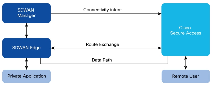
Private application access using Cisco SD-WAN Manager is a secure connection that enables remote Cisco IOS XE Catalyst SD-WAN devices and Cisco secure routers to access private applications through Cisco Secure Access.
BGP route advertisement and IPSec tunnels
Remote users require secure access to private applications hosted behind the WAN edge device. To facilitate this, Border Gateway
Protocol (BGP) prefixes are exchanged with the Secure Service Edge (SSE)'s with Cisco Secure Access as the provider, enabling
dynamic route learning to the private applications located behind the WAN edge. Traffic destined for these private applications
is routed over secure IPSec tunnels established between the WAN edge and the SSE provider. These tunnels operate within service
VPN. By advertising BGP routes, a secure and dynamic channel is created between the network behind the WAN edge and the SSE
provider, which carries service-side traffic.
Figure 1. Private application access architecture
Secure private application access for multi-region network
This example of an architecture for secure private application access describes routing policies for integrating a multi-region
SD-WAN overlay network with Cisco Secure Access to facilitate secure access to private applications. The design emphasizes
on:
redundancy
optimal path selection
critical traffic symmetry.
Architecture overview
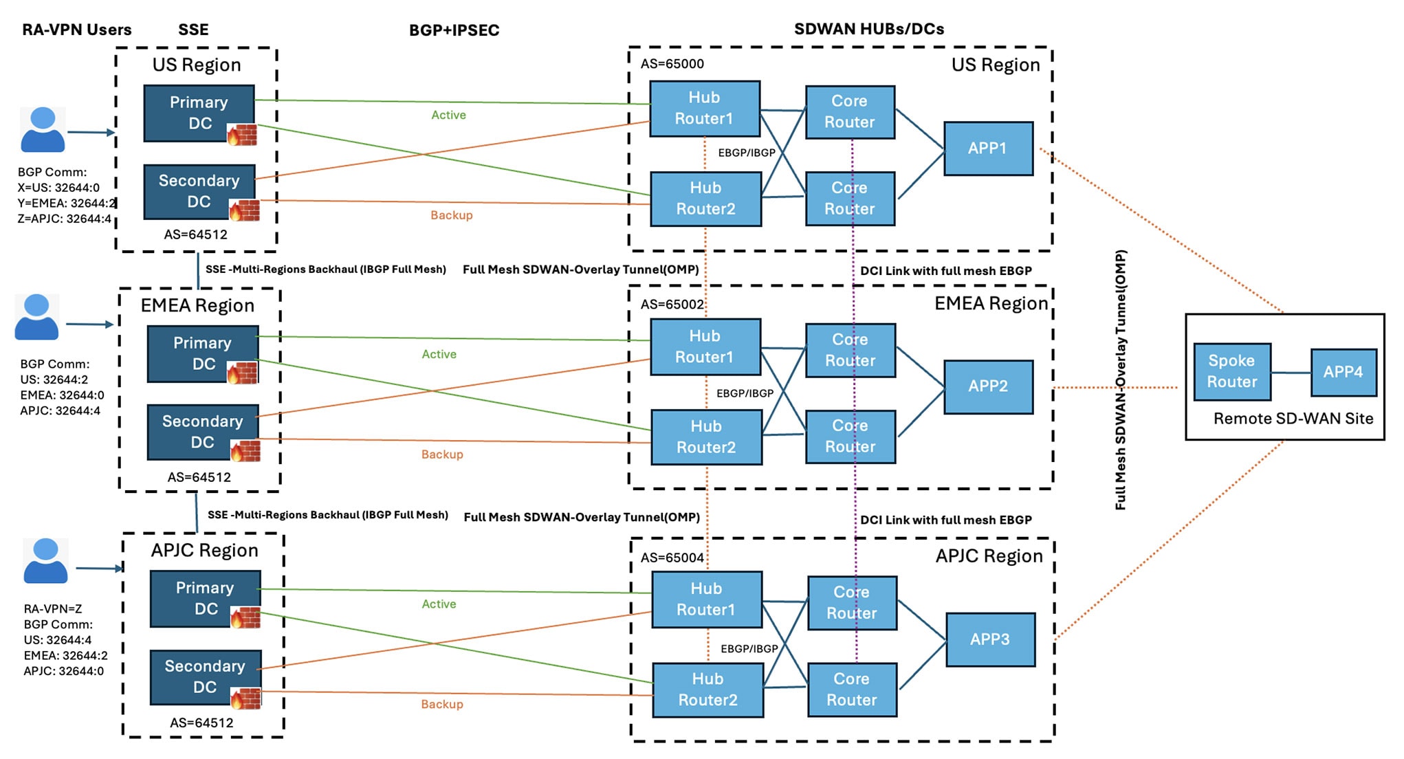
Figure 2. Example generic topology: SD-WAN hubs deployed in Active/Active Model
The topology can span across multiple SSE regions. The core components of the topology are:
RA users: End-users connecting remotely to the network through Cisco Secure Client.
SSE regions: Each region hosts a primary and a secondary data center. These data centers are interconnected via an internal
BGP backbone with Multi-region Backhaul capabilities. For more information, see Cisco SASE Design Guide.
SD-WAN Hubs: Each region can contain multiple hub routers. These hubs operate under distinct AS numbers.
Applications: Private applications can be hosted behind the hub or spoke routers within the SD-WAN network.
Application in US region is app1, application in EMEA region is app2, and application in APJC region is app3.
Connectivity and interoperability
SSE to SD-WAN hubs: Each SD-WAN hub connects to its closest Cisco Secure Access Region through redundant IPsec tunnels. For
example, SD-WAN hub in US region connects to the SSE US region and vice versa.
Active tunnels terminate on the active SSE data center, while standby tunnels connect to a redundant standby data center within
the same region.
Within the primary data center, there can be multiple active ECMP tunnels from a SD-WAN hub router to provide a higher throughput.
SD-WAN hubs to remote sites: A full mesh SD-WAN overlay tunnel provides connectivity between the SD-WAN hubs and remote SD-WAN
users.
Routing policies and traffic management
The routing design prioritizes redundancy, regional preference, and maintains traffic symmetry to prevent packet drops by
SSE firewalls.
Unique regional application routes are advertised from each hub to its nearest SSE PoP (Point of Presence) regions.
Remote access VPN pool routes are advertised from all SSE regions towards the SD-WAN Hubs.
Remote users terminating in SSE US region can access applications in any SD-WAN region. All traffic, both incoming and outgoing,
follows a symmetric path, using only the active tunnels for connectivity if the primary tunnels are active. If the primary
tunnels are not active, then the secondary tunnels are used.
Remote access pool IP routes are advertised from all SSE regions, each with a community tag indicating its priority based
on the local region and neighboring regions. For example, VPN pool routes for a remote user in US region are advertised with
priority 0 in US region, priority 2 in EMEA region, and priority 4 in APJC region, reflecting the distance from the user’s
original region.
These prioroities can be used to maintain routing controls and loop preventions.
The table displays how each region advertises the same remote VPN pool IP addresses with different priority values, depending
on their proximity to other regions. These fixed priorities are built into the Cisco Secure Access BGP stack: the farther
a prefix is from its original region, the higher its priority number. This logic is automatically applied when SSE PoP (Point
of Presence) regions advertise routes from other regions. Routes within the local region always have a priority of '0'. For
more information on how Cisco Secure Access handles traffic, see Dynamic Routing with BGP.
RA VPN pool prefix community value
US Region
EMEA Region
APJC Region
x
32644:0 (local)
32644:2
32644:4
y
32644:2
32644:0 (local)
32644:4
z
32644:4
32644:2
32644:0(local)
Route policies on SD-WAN service interfaces using CLI
Sample policy for route control
The example describes flows and policies based on the sample topology.
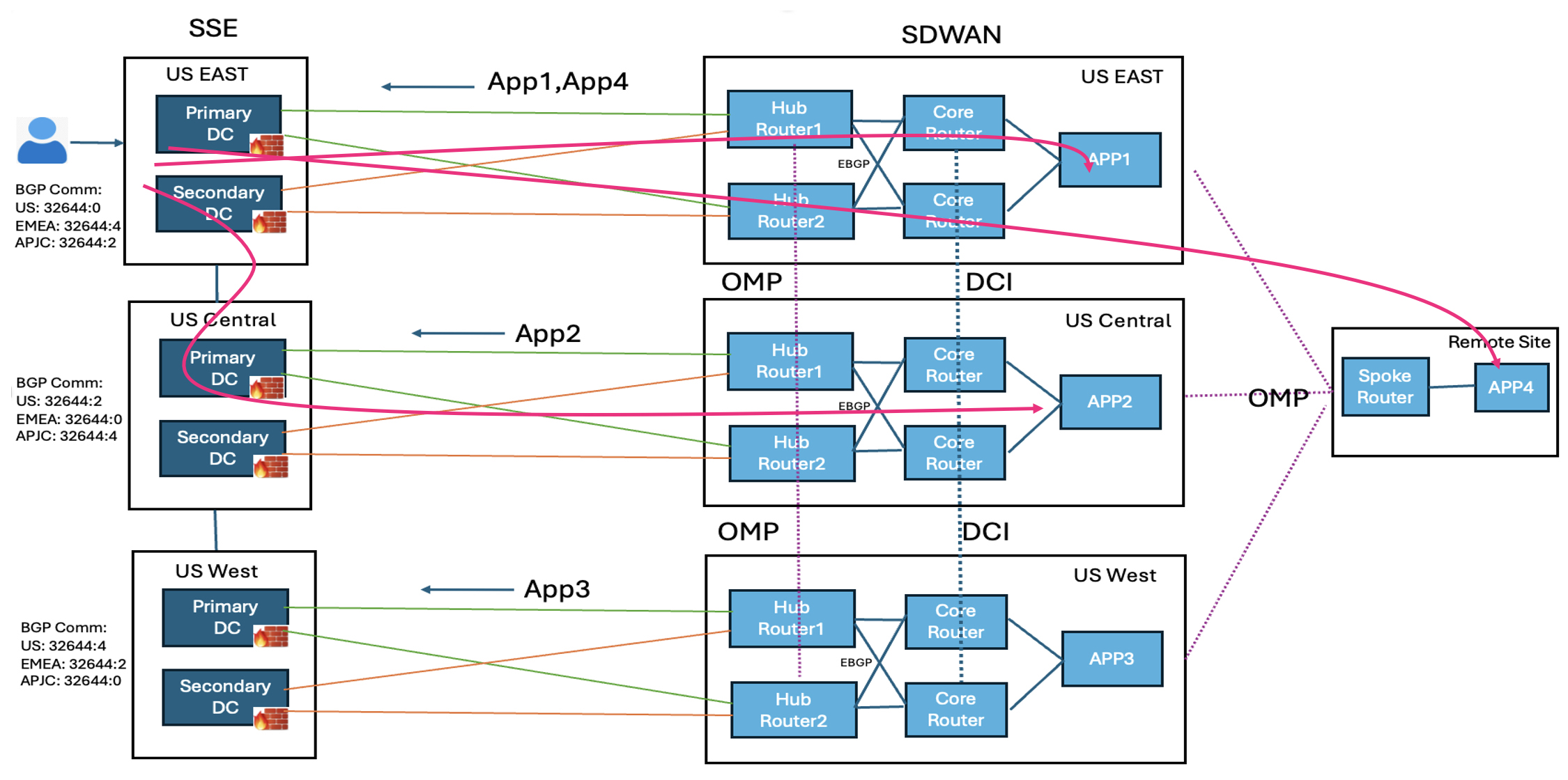
Figure 3. Traffic advertisement and flow to block routing on data center interconnect with SSE Multi-region Backhaul
The applications, app1 and app4, can be advertised from US East region and blocked from other regions. Similarly app2 is advertised
from US Central, and app3 from US West.
For a remote user in the SSE US East region to access app1, the traffic flows through the SD-WAN tunnels in the US East region
to the US East hub routers. To access app2, the traffic travels via the SSE Multi-region Backhaul backbone to the US Central
region, passes through the SD-WAN tunnels to the US Central hub routers, and then reaches app2. To access app3, the traffic
moves through the SSE Multi-region Backhaul backbone to the US West region, goes through the SD-WAN tunnels to the US West
hub routers, and then reaches app3.
The traffic first uses the primary tunnels. If the primary tunnels to one hub router are down, the traffic switches to the
primary tunnels of the second hub router. Only when all primary tunnels are down the traffic uses the secondary tunnels.
SSE import policy on SD-WAN hubs
This is an example of a sample route policy configuration.
ip as-path access-list 1 permit _60001_
ip community-list expanded ALL_SSE_COMM permit ^32644:.*
ip community-list expanded DCI_COMM permit ^50001:.*
ip community-list expanded HUB_OMP_COMM permit ^60001:.*
Import Policy for primary tunnel BGP towards SSE on Hub routers:
---------------------------------------------------------------------------------------
route-map IMPORT_SSE_PRIMARY deny 1
    match as-path 1
route-map IMPORT_SSE_PRIMARY permit 2
    match community ALL_SSE_COMM
route-map IMPORT_SSE_PRIMARY deny 65534
Import Policy for secondary tunnel BGP towards SSE on Hub routers:
--------------------------------------------------------------------------------------------
route-map IMPORT_SSE_SECONDARY deny 1
    match as-path 1
route-map IMPORT_SSE_SECONDARY permit 2
    match community ALL_SSE_COMM
    set as-path prepend 32644
route-map IMPORT_SSE_SECONDARY deny 65534
OMP AS-path on SD-WAN hub routers
The route policy imports SSE prefixes and prepends the AS path based on community and metric. On hub routers, you can convert
the AS path length to OMP preference, so that the spoke routers prefer the correct hub router for the reverse path to reach
SSE prefixes.
sdwan
     omp
          overlay-as       60001
Service side BGP import route policy on SD-WAN hub routers
On the service side of hub routers with external BGP neighbors, create an import route policy that rejects any prefixes with
the SSE community. Core routers on the SD-WAN side can export SSE prefixes to other regions through data center interconnects,
which returns to SD-WAN hub routers of other regions via external BGP. This import policy blocks those prefixes from the data
center core routers.
route-map IMPORT_CORE deny 1
         match community ALL_SSE_COMM
route-map IMPORT_CORE deny 2
         match as-path 1
 route-map IMPORT_CORE permit 65534
Export policy to SSE on SD-WAN hub routers
Create an export route policy toward SSE neighbors that rejects any prefixes with the SSE community. Hub routers learn SSE
prefixes through OMP from hub routers of other regions, so you should filter these routes before exporting them to SSE neighbors.
Export Policy for both primary and secondary tunnel BGP towards SSE:  (For HUBs which is not exporting spoke routes to SSE)
---------------------------------------------------------------------------------------------
route-map EXPORT_SSE deny 1
    match community ALL_SSE_COMM
    match community DCI_COMM
    match community HUB_OMP_COMM
route-map EXPORT_SSE deny 2
    match as-path 1
route-map EXPORT_SSE permit 65534
Export Policy for both primary and secondary tunnel BGP towards SSE: (For HUBs which is exporting spoke routes to SSE)
---------------------------------------------------------------------------------------------
route-map EXPORT_SSE deny 1
    match community ALL_SSE_COMM
    match community DCI_COMM
    match community HUB_OMP_COMM
route-map EXPORT_SSE permit 65534
OMP export policy on hub routers
Create an export route policy for OMP on hub routers.
For hubs which is exporting spoke routes to SSE
route-map EXPORT_OMP permit 1
          set community 60001:1
route-map EXPORT_OMP deny 65534

sdwan
   omp
     auto-translate
          as-path-length
          to-route-preference
      !
      address-family ipv4 vrf 1
          advertise bgp route-map EXPORT_OMP
      !
For hubs which is not exporting spoke routes to SSE
route-map EXPORT_OMP deny 1
          match community ALL_SSE_COMM
route-map EXPORT_OMP permit 2
          set community 60001:1
route-map EXPORT_OMP deny 65534

sdwan
   omp
      address-family ipv4 vrf 1
          advertise bgp route-map EXPORT_OMP
  !
Usage guidelines for private application access
Enabling private application access for existing organizations
If you created your Cisco Secure Access organization before Cisco IOS XE Catalyst SD-WAN Release 17.18.1a, contact Cisco TAC to enable the private application access functionality. Additionally, contact your account team to validate
your design.
Regions
Each WAN edge device can have 10 active and 10 backup tunnels.
Each SSE region can have one Network Tunnel Group with 40 active and 40 backup tunnels.
Multi-region Backhaul
By default, Multi-region Backhaul feature is enabled on Cisco Secure Access as part of the automation which helps control
routing using communities advertised by SSE. For more information, see Cisco SASE Design Guide.
BGP configurations
By default, Cisco SD-WAN Manager configures a deny-all policy for BGP to ensure controlled route advertisement between the Cisco SD-WAN overlay and Cisco
Secure Access. You must manage any modifications to the BGP route-map configurations created during the workflow using the
CLI Add-On Template.
Unique SSE credentials and organization ID across multiple Cisco SD-WAN Manager instances
If there are two Cisco SD-WAN Manager instances in the SD-WAN overlay, each Cisco SD-WAN Manager instance has its own SSE credentials and organization ID and the tunnel is unique to that instance. The SSE tunnels cannot
be shared across Cisco SD-WAN Manager instances.
NAT interface and tunnel-route-via configurations
When a NAT interface is removed from a configuration group and is used as the tunnel-route-via interface in the private application
feature, the tunnel-route-via interface becomes invalid. This makes the tunnels that relied on the NAT interface unreachable.
The tunnel status appears as unreachable on both the monitoring dashboard and the SSE portal.
If a NAT interface used as a tunnel-route-via interface is removed:
Deploy the policy group once again so that the first available NAT interface is selected. If there are no NAT interfaces,
then Cisco SD-WAN Manager displays an error.
Update a valid NAT interface manually, and then deploy the policy group.
This ensures that the tunnel-route-via interface is valid and tunnels remain operational after you make any changes to the
NAT interfaces in the configuration group.
BGP hold time
BGP determines the maximum duration for traffic black holing based on its hold time, which is set to 180 seconds (3 minutes)
by default.
Workflow for private application access
The private application access workflow automates configurations on a Cisco IOS XE Catalyst SD-WAN device.
Before you begin
Ensure that a configuration group with a defined VPN is associated to the selected WAN edge devices and deployed.
You can configure all route policies using configuration groups. However, you must configure the incoming route policy for
the SSE neighbor through the CLI Add-On template.
Ensure that you add valid Cisco Secure Access credentials in Administration > Settings > Cloud Credentials.
Configure the DNS server on Cisco SD-WAN Manager to connect to Cisco Secure Access
Procedure
Step 1
From the Cisco SD-WAN Manager menu, choose Workflows > Workflow Library.
Step 2
Click the Configure Secure Private Application Access Connectivity workflow.
Step 3
Follow the on-screen instructions to complete the private application access workflow.
Field
Description
Segment (VPN)
Select the service VPN hosting the application from the drop-down list.
If you don't have a configuration group with a defined VPN, you can define your own segment in the editable field here. Ensure
that you deploy the segment in the configuration group.
Cisco Secure Access Region
Choose the SSE regionfrom the drop-down list. The SSE region that you choose must be close to the SD-WAN hub hosting the application.
The regions are available in the drop-down list only if valid Cisco Secure Access credentials are added to the Administration
Settings page.
Tunnel Configuration
Click Add tunnel pair to add additional tunnel pairs to the configuration.
By default, the tunnel source is a system created loopback interface for ECMP support. The tunnel route-via interface is the
first NAT'ed physical WAN interface on the edge device. Based on the WAN edge device's configuration groups which has configured
NAT, the tunnel pair is auto detected.
Click the edit icon for a tunnel pair to change the primary and secondary tunnel source and destination interfaces.
BGP ASN
Enter the local BGP AS number associated to the region that you choose. Each region is associated to only one ASN.
AS number of the SD-WAN hub site should not match the SSE AS number.
If you create another workflow with the same region, the AS number is autopopulated and non-editable.
In Route Policy
Specify a name for the inbound routes.
Out Route Policy
Specify a name for the outbound routes.
The route policy name is the name of the routing policy used to exchange routes between Cisco SD-WAN and Cisco Secure Access.
The route policy name creates a CLI add-on policy with deny all policy by default. We recommend that you use CLI Add-On Template
to change the route policy and BGP configurations to control route advertisements.
Step 4
Optionally you can associate the feature to a Policy Group.
Step 5
You can review the summary and click Create Connectivity.
After you create connectivity, Cisco SD-WAN Manager creates a private application access feature under policy group.
What to do next
Click Configuration > Policy Groups, select the associated policy group, and click Deploy to establish the tunnel connectivity.
Monitor SIG/SSE Tunnels
Use the security operations dashboard to monitor the status and performance of SSE tunnels.
From the Cisco SD-WAN Manager menu, choose Monitor > Security.
The SIG/SSE Tunnel Status pane shows the following information using a donut chart:
Total number of SIG/SSE tunnels that are configured.
The number of SIG/SSE tunnels that are up and down.
The number of SIG/SSE tunnels that are in a degraded state.
Degraded state indicates that the SIG tunnel is up but the Layer 7 health of the tunnel as detected by the tracker does not
meet the configured SLA parameters. Traffic is not routed through the tunnel.
(Optional) Click a section of the donut chart to view detailed information about tunnels having a particular status.
Cisco SD-WAN Manager displays detailed information about the tunnels in the SIG/SSE Tunnels dashboard.
(Optional) Click All SIG/SSE Tunnels to view the SIG/SSE Tunnels dashboard.
Troubleshooting Using Cisco SD-WAN Manager
You can troubleshoot provisioning errors or view the remote tunnel status using the audit logs. For more information, see
View Audit Log Information.
 Feedback