Cisco SASE Design Guide
Available Languages
Bias-Free Language
The documentation set for this product strives to use bias-free language. For the purposes of this documentation set, bias-free is defined as language that does not imply discrimination based on age, disability, gender, racial identity, ethnic identity, sexual orientation, socioeconomic status, and intersectionality. Exceptions may be present in the documentation due to language that is hardcoded in the user interfaces of the product software, language used based on RFP documentation, or language that is used by a referenced third-party product. Learn more about how Cisco is using Inclusive Language.
Contents
Remote User to Private Application
Branch User to Private Application
Equal Cost Multi-Path (ECMP) Load Balancing
Trusted Network Detection (TND)
BGP Prefix advertisement with Multi-Region Backhaul
Today’s workforce continues to demand seamless, secure access to applications from any location, on any device. With the normalization of remote and hybrid work, the expansion of organizational data and infrastructure into the cloud, and the growing reliance on Software as a Service (SaaS) applications like Microsoft 365 and Salesforce, internet-bound traffic has surged. Additionally, diverse users including employees, contractors, partners, and a wide array of devices, such as Internet of Things (IoT) endpoints, require secure, flexible network access, regardless of location. IT teams must now deliver consistent security and optimized application performance for every user and device, treating each as a “branch of one,” wherever they are located.
Traditional, data center-centric network models have become increasingly costly and inefficient for managing this distributed traffic. Key challenges include:
● Sustained remote and hybrid work: User mobility is now foundational, with workers accessing resources continuously from any location.
● Expanded attack surface: The proliferation of distributed users, devices, and cloud applications increases security complexity and risk.
● Performance limitations: Legacy networking and security architectures struggle to provide the application performance and user experience required for modern cloud services.
To address these challenges, organizations now require a unified, agile approach to networking and security. Recent advancements in Secure Access Service Edge (SASE) have accelerated the convergence of networking and security services—such as Software-Defined Wide Area Networking (SD-WAN), cloud-delivered security, and identity-based access—at the network edge, closer to users and devices. SASE solutions have become more integrated, leveraging Artificial Intelligence (AI)-driven automation, advanced threat intelligence, and unified policy management to deliver consistent, context-aware protection and performance. SASE also supports granular, zero trust access controls and improved visibility across distributed environments, ensuring organizations can securely connect people, devices, and applications anywhere, at any time.
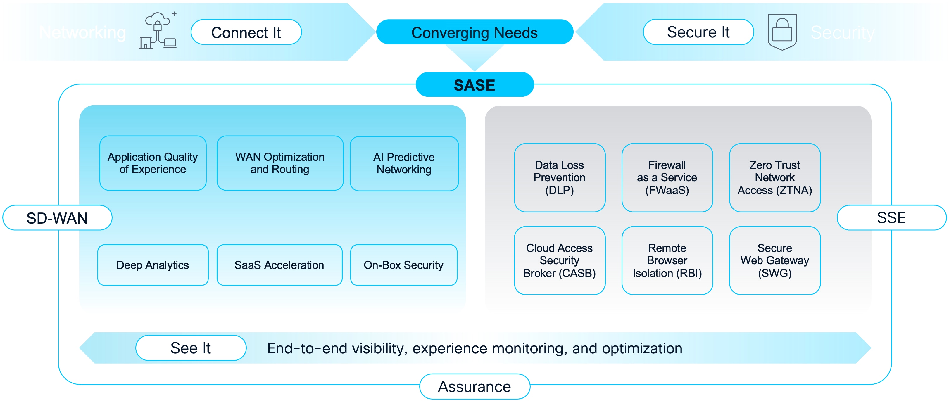
SASE Overview
By adopting the latest SASE architecture, IT can provide secure, reliable, and scalable access while simplifying management, reducing costs, and enhancing user experience in today’s dynamic, cloud-first world.
This design guide will provide an overview of the Cisco SASE solution with a focus on Security Service Edge (SSE) using Secure Access along with best practices and strategies that can be used for implementing Cisco SASE in your network.
● BGP (Border Gateway Protocol) routing
● High Availability Deployments
● Multi-Region Backhaul (MRB)
● Other SASE Best Practices with a focus on Secure Access
● Secure Internet Access
● Private Access Rules and Private Resource Creation
● Cisco SD-WAN (Catalyst SD-WAN, Meraki SD-WAN, Secure Firewall SD-WAN) Integration with Secure Access and Best Practices (Intended for a future version of this design guide)
Cisco Secure Access Service Edge is Cisco’s integrated approach to unifying secure access and wide-area networking. By combining Cisco Secure Access with one of Cisco’s SD-WAN solutions, organizations can simplify network architecture, enhance security, and enable flexible connectivity for users and applications wherever they are located.
Cisco’s SASE strategy is designed to meet organizations at any stage of their networking journey, providing flexible options for evolving from SD-WAN to SASE or from Security Service Edge (SSE) to SASE. Cisco offers a portfolio of SD-WAN solutions to address diverse deployment models and organizational requirements:
Cisco Catalyst SD-WAN
Cisco Catalyst SD-WAN (formerly Viptela) is a secure, cloud-scale architecture designed to be highly programmable, open, and scalable. It provides comprehensive capabilities for connecting data centers, branches, campuses, and colocation facilities, offering advanced features such as multi-cloud access and secure segmentation. The solution is built upon a flexible architecture of vEdge routers, vSmart controllers, vManage, and vBond orchestrators. The primary audience for Catalyst SD-WAN includes large enterprises and complex networks that demand extensive customization, granular control over routing policies, and sophisticated network functionalities. The solution is administered through the Cisco vManage console, which delivers deep control, analytics, and versatile deployment options, including cloud-hosted, on-premises, or public cloud. It incorporates integrated security features like a base firewall, URL filtering, and IPS.
Cisco Meraki SD-WAN
Cisco Meraki SD-WAN is recognized for its simplicity and ease of management, enabled by a centralized cloud-based platform. Key features include zero-touch provisioning, automatic updates, dynamic path selection, and application awareness. Its primary audience includes mid-size organizations or those with lean IT operations who value rapid deployment and a cloud-first management experience. The solution is entirely cloud-managed through an intuitive dashboard, emphasizing ease of use and streamlined operations. Meraki SD-WAN includes built-in security features such as integrated threat protection, intrusion detection, and advanced firewall capabilities, providing a natively secure SD-WAN solution that is simple to deploy.
Cisco Secure Firewall SD-WAN
Cisco Secure Firewall SD-WAN integrates advanced Next-Generation Firewall (NGFW) capabilities directly with SD-WAN functionalities. The primary focus is to deliver robust, integrated security at the branch or network edge, combining network connectivity with comprehensive threat protection. This solution is designed to mitigate cyber threats, particularly in environments adopting direct internet access (DIA) and cloud-based applications from branch locations. This solution is managed through a single pane of glass, unifying routing and security management. This solution is ideal for branches needing robust, integrated security directly at the network edge. Administration is integrated with existing Cisco Secure Firewall tools, offering a unified management experience for both routing and security. As a security-first solution, Cisco Secure Firewall SD-WAN embeds NGFW capabilities at the edge, balancing advanced security with SD-WAN functionality to simplify secure branch deployments.
By selecting the appropriate Cisco SD-WAN solution as part of a SASE architecture, organizations can align their networking and security strategies to their operational needs whether it involves prioritizing advanced networking, streamlined cloud management, or security-centric connectivity. Cisco’s flexible SASE approach enables seamless transitions and future-ready network designs.
Cisco SASE is designed to address a wide variety of modern connectivity and security needs, enabling organizations to deliver secure access to users located anywhere, at any time.
This section highlights common use cases that can be addressed with Cisco SASE, with a primary focus on those scenarios supported by Cisco Secure Access. These use cases demonstrate how organizations can protect remote workers, branch offices, and cloud resources, regardless of the underlying SD-WAN solution deployed.
Remote User to Private Application
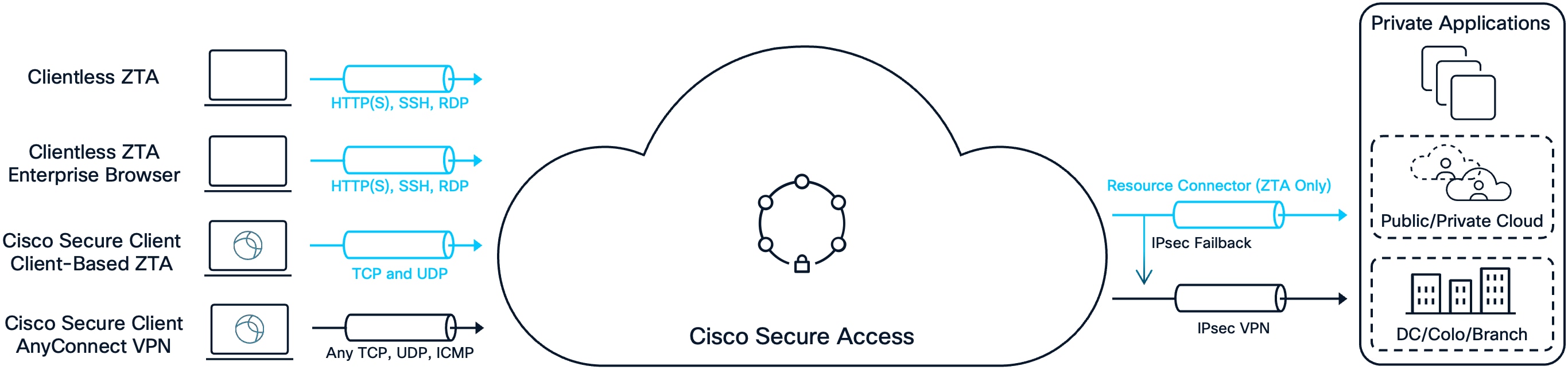
Remote User to Private Apps
Clientless ZTA
This approach leverages the Zero Trust Access (ZTA) proxy built into Cisco Secure Access to facilitate a clientless ZTA experience for users. The user simply opens a browser, navigates to the appropriate URL, and completes authentication and authorization steps. Although posture checks are more limited in this scenario, it enables easy access to supported applications. At the time of publication, clientless ZTA supports HTTP(S), SSH, and RDP protocols. For applications utilizing other protocols, alternative methods—such as Client-Based ZTA or Remote Access VPN (RAVPN)—are required.
Clientless ZTA (Enterprise Browser)
This method similarly uses the ZTA proxy to facilitate a clientless ZTA experience, but with enhanced device posture assessment using an Enterprise Browser. In addition to the Secure Access posture checks available for Clientless ZTA, the enterprise browser provides local posture checks including clipboard controls, process isolation, screenshot protection, and more. At the time of publication, this solution integrates with the Chrome Enterprise Browser.
Client-Based ZTA for Secure Private Access
In addition to the integrated ZTA proxy within Secure Access, Client-Based ZTA leverages the Cisco Secure Client ZTA module to establish secure connections to remote applications. This approach supports a broader range of application protocols and delivers more granular posture assessments compared to the clientless method. Users enroll (authenticate) once, after which access is maintained transparently by default—even following a system reboot—delivering a seamless user experience. Posture requirements are enforced the first time a user accesses an application over the ZTA module, rather than only at connection time like VPN. Access to private resources is always proxied, ensuring users never have direct network access and that private resource IP addresses remain hidden. As a result, only client-to-server communications are supported with this approach. At the time of publication, the ZTA module supports Trusted Network Detection and Secure Internet Access use cases to specific destinations, allowing a user to reach both private resources and connect securely to specific Internet destinations while the ZTA module is enabled and enrolled.
AnyConnect VPN for Secure Private Access
Traditionally, VPNs have provided remote users with access to private resources by establishing secure connections to on-premises devices in the data center. In this classic data center-centric model, users connect to private applications through a VPN client, routing traffic through the corporate network.
However, with the shift to remote and hybrid work, and the growing need for users to access Internet and SaaS applications that are not hosted in the data center, this approach no longer fully meets modern requirements. On-premises devices can become overloaded as remote access becomes standard, and administrators must now also manage Internet-bound traffic alongside private application access.
VPN-as-a-Service (VPNaaS) addresses these challenges. Cisco Secure Access supports VPNaaS through the Cisco Secure Client AnyConnect VPN module, which enables secure remote access for all TCP, UDP, and ICMP protocols using TLS/DTLS or IKEv2. The solution offers advanced device posture assessment via the Secure Firewall posture module or Identity Services Engine (ISE) posture module, supports multiple authentication methods, and provides features to manage VPN behavior—such as Trusted Network Detection and management tunnels. Importantly, VPNaaS within Secure Access allows users to securely connect both to private resources and the Internet simultaneously.
VPNaaS is also an ideal bridge for organizations transitioning from traditional remote access VPN (RAVPN) solutions. Customers can first move from their on-premises VPN infrastructure to VPNaaS, gaining the benefits of cloud-managed access and simplified operations. As applications become ready and are supported by ZTA, organizations can transition access of these applications to ZTA module. Applications that are not yet supported by ZTA—such as server-to-client or client-to-client use cases—can continue to use VPNaaS, ensuring uninterrupted access throughout the migration process.
While VPN solutions are robust, they may offer a less seamless user experience compared to ZTA. Users often need to manually initiate connections and authenticate, although options like certificate authentication and Always On VPN help automate this process. VPNs operate at the network layer, which means private resource IP addresses are visible and, without strong security policies, users may receive broader access than intended. In contrast, ZTA proxies function at the application layer, providing a more transparent and granular approach.
To enhance security, Secure Access denies all private access traffic by default. Only after explicit private access rules are defined can users reach permitted applications and resources. Furthermore, device posture checks are enforced through the previously mention modules, making Secure Access VPNaaS significantly more secure than traditional remote access VPN solutions.
In summary, while Secure Access VPNaaS does not offer per-application segmentation like ZTA, it is still considered more secure than traditional VPN architectures and complements ZTA in several ways:
● Secure Connectivity for Incompatible Resources: VPNaaS enables secure access to private resources that are not compatible with ZTA, such as scenarios where the server initiates connections to the client.
● Simplified Migration Path: Transitioning from traditional VPN to VPNaaS is straightforward and can serve as a bridge for customers moving toward a ZTA model. Secure Access also streamlines migration from ASA platforms with a built-in migration process.
● Seamless Coexistence: The VPN and ZTA modules within Cisco Secure Client can operate simultaneously and transparently, supporting both use cases without user intervention.
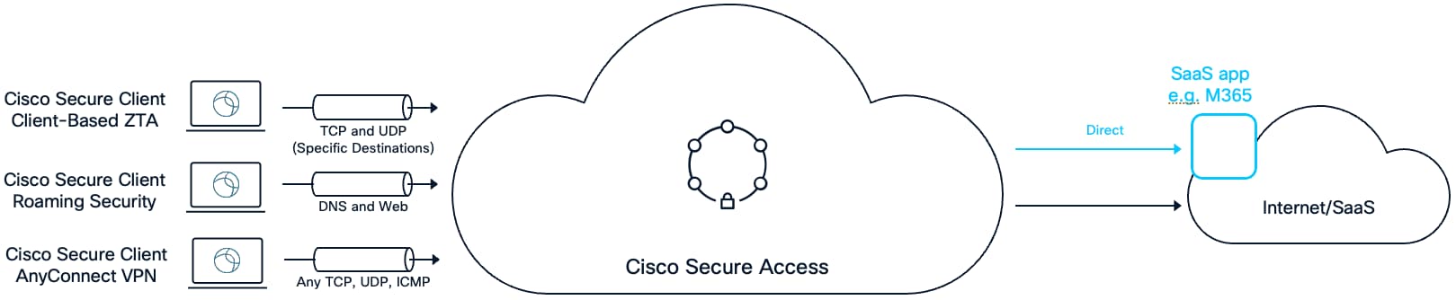
Remote User to Internet/SaaS Apps
Client-Based ZTA for Secure Internet Access
Using the Secure Client ZTA module, specific Internet or SaaS destinations can be proxied through Secure Access. This method of Secure Internet Access addresses use cases where an Internet accessible service only allows access to traffic that originates from IP addresses that are within an organization's IP address space. This feature supports both TCP and UDP protocols (including non-web traffic) and is protected by Secure Access Internet security controls such as Secure Web Gateway (SWG) and Data Loss Prevention (DLP). Users enroll (authenticate) to the ZTA module once, after which access is maintained by default.
Roaming Security
Cisco Secure Client also provides Secure Internet Access (SIA) for end users via the Roaming Security module (also known as the Umbrella module). Because this module is also used by Cisco Umbrella customers, migration from Umbrella to Secure Access can be simplified. The Roaming Security module protects both HTTP(S) and DNS by proxying this traffic to Secure Access. User Authentication is not required, and the protection begins as soon as the user logins to their device. Endpoints that have successfully had the Roaming Security module installed on them will be added to an identity known as Roaming Devices within Secure Access. The module can send the User Principal Name (UPN) of the logged in user to Secure Access for identity-based access control, enabling granular internet access policies.
Note: Only HTTP(S) and DNS traffic are protected with this method. While SWG, DLP, and SSL Decryption is supported, firewall-based security features, such as Intrusion Prevention System (IPS), are not supported
AnyConnect VPN for Secure Internet Access
In a traditional architecture, remote access VPN was used to protect both private resource and internet traffic by tunneling all traffic to a firewall. Both Internet and private resource traffic were sent over an encrypted tunnel to a firewall where private traffic was sent internally, and Internet traffic was “hair pinned” back out to the Internet. This use case is still supported by Secure Access, or customers may choose to route only internet traffic over VPN for SIA, based on requirements.
Because VPN can forward any TCP, UDP, and ICMP protocols to Secure Access, customers can leverage the combination of VPN for traffic acquisition and the Firewall as a service (FWaaS) feature for Internet bound traffic, which allows non-web traffic to be processed. Evaluation through Secure Access FWaaS also enables Intrusion Prevention System (IPS) inspection.
Note: One disadvantage of VPN for SIA use cases is the impact on user experience. Users may need to manually initiate a VPN connection and enter their credentials before their sessions are secured. To streamline this process, it is highly recommended to configure Trusted Network Detection with Always On, and to use certificate-based authentication for a passwordless experience. With this setup, the AnyConnect VPN module secures Internet traffic, while the ZTA module can be configured to protect access to private applications. Both modules work together seamlessly, providing comprehensive protection without requiring any user intervention.
Branch User to Private Application
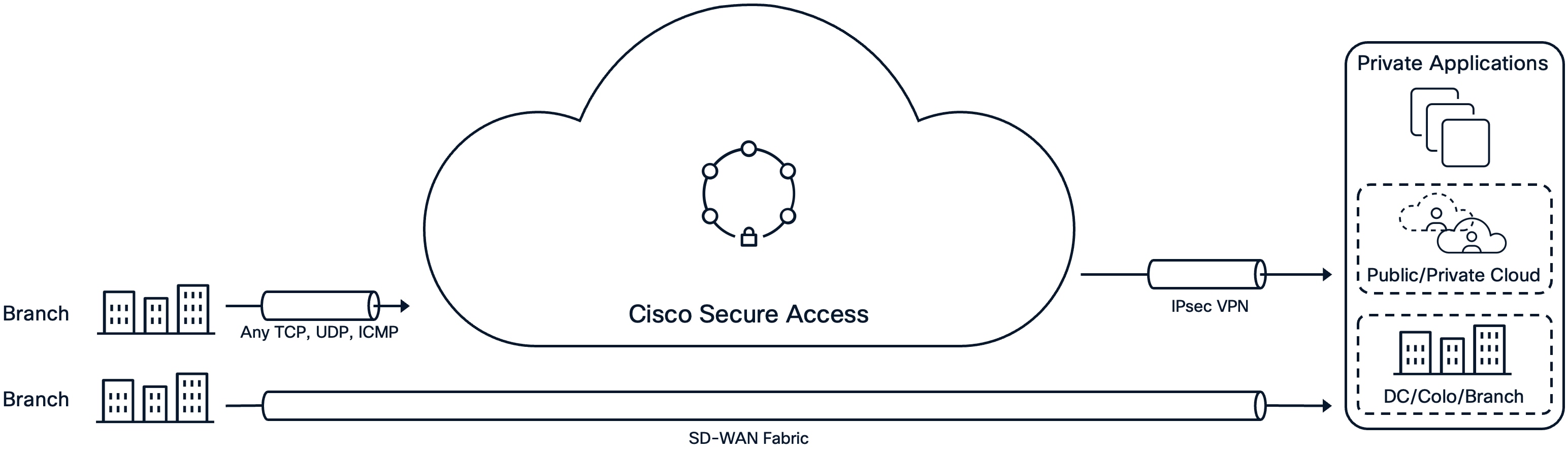
Branch User to Private Apps
Secure Access supports Secure Private Access (SPA) for branch users and devices. By connecting branch sites to Secure Access using IPsec VPN tunnels, traffic to private applications can be securely forwarded between sites with Secure Access as the hub.
Branch User to Internet/SaaS Apps
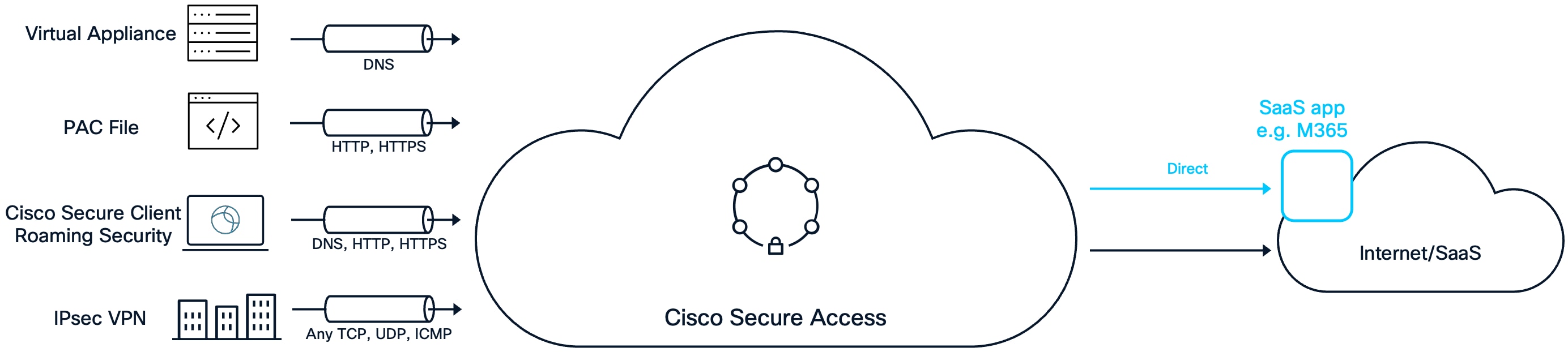
Virtual Appliance (VA)
Domain Name Resolution (DNS) is one of the first steps executed by an endpoint when reaching out to Internet resources. By implementing DNS based protections, organizations can efficiently prevent access to malicious sites. The Virtual Appliance (VA) is a tool that identifies users and facilitates the protection of users and endpoints at the DNS layer. The VA is assigned as the primary DNS server on endpoints and devices through methods such as Dynamic Host Configuration Protocol (DHCP). When the endpoint sends a DNS request, if the request is for an Internet destination it forwards it to Secure Access for evaluation and resolution. The VA provides additional context to the DNS request including the local IP address, the customer’s ID so it can be associated with the customer’s Secure Access organization, and, if integrated with AD, the user’s username and group identities. DNS requests for local domains are directed to the organization’s internal DNS server.
PAC File
A proxy auto-config (PAC) file is a configuration used by browsers to determine whether traffic should be sent directly to an internet resource or routed through a proxy. By deploying PAC files, organizations can leverage the SWG functionalities within Secure Access, enabling protection of HTTP(S) traffic through Internet access policy rules. This method is supported when the endpoint is on the network (not roaming) and the public (egress) IP for that branch network is registered with Secure Access.
Roaming Security for Branch-Based Secure Internet Access
Cisco Secure Client Roaming Security module while typically used to protect internet traffic for roaming users, it can also be leveraged for protecting DNS and web traffic within a branch. When used this way, DNS and/or web traffic is send to the customer’s Secure Access organization where it will get the same SIA protections as the customer would get if they were remote (DNS, SWG, DLP, SSL Decryption). Like the VA, the Roaming security module will provide additional context (local IP address, the customer’s, and, if integrated with AD, the user’s username and group identities). The Roaming Security module can also be configured with Trusted Network Detection, disabling DNS or both DNS and web traffic from being sent to Secure Access when the user is on a corporate network. This provides the customer with multiple options for how they can setup the Roaming Security module in their network.
IPsec VPN for Secure Internet Access
Secure Internet Access via IPsec VPN provides Internet protection for all UDP, TCP, and ICMP traffic, not just web traffic. Using IPsec VPN to create a connection from the branch to Secure Access allows customers to take advantage of the FWaaS protections within Secure Access. These include features such as controlling predefined Application Protocols and IPS.
This solution can be combined with a Virtual Appliance to ensure DNS query protection and to identify the internal network and users associated with DNS requests that might otherwise go undetected.
Designing a Cisco SASE solution requires careful planning to ensure that the network is secure, resilient, and scalable. Although the process can be complex, following proven strategies and best practices can help you achieve a successful outcome.
This section provides practical guidance on key design elements, including routing (static and BGP), high availability, and Equal Cost Multi-Path (ECMP) load balancing. By applying these recommendations, organizations can build a Cisco SASE solution that meets current requirements and supports future growth.
The following best practices and strategies are recommended when designing a SASE solution with Cisco Secure Access.
High Availability (HA) is essential for ensuring consistent access to private resources and ensure uninterrupted secure connectivity to the Internet and SaaS applications. IPsec tunnel connections between customer sites and Secure Access regions are established using IKEv2 tunnels, which are logically grouped into Network Tunnel Groups (NTG). All Secure Access regions have a primary and secondary data center to ensure HA on the cloud side. Customers are responsible for implementing HA at the premises level. Depending on the Customer Premises Equipment (CPE) device, Secure Access supports both Active/Standby and Active/Active failover, giving customers flexibility in how they integrate their devices with their data centers, branches, and private clouds.
For additional guidance on NTGs and HA, refer to the Cisco documentation on Network Tunnel Groups.
Single Device High Availability
Single Device High Availability
Advantages
● Simpler Deployment and Management: IPsec and routing configurations are required on only one device, reducing setup complexity and administrative overhead.
● Lower Cost: Only a single device needs to be licensed, maintained, and monitored, minimizing hardware and support expenses.
Disadvantages
● Single Point of Failure: If the single CPE device fails, there is no backup device available, resulting in service interruption.
● Limited Scalability: All traffic and processing are managed by a single device, which may become a bottleneck as demand grows.
● Downtime During Maintenance: Any maintenance or upgrades on the single device will cause network downtime, as it is the only device routing traffic.
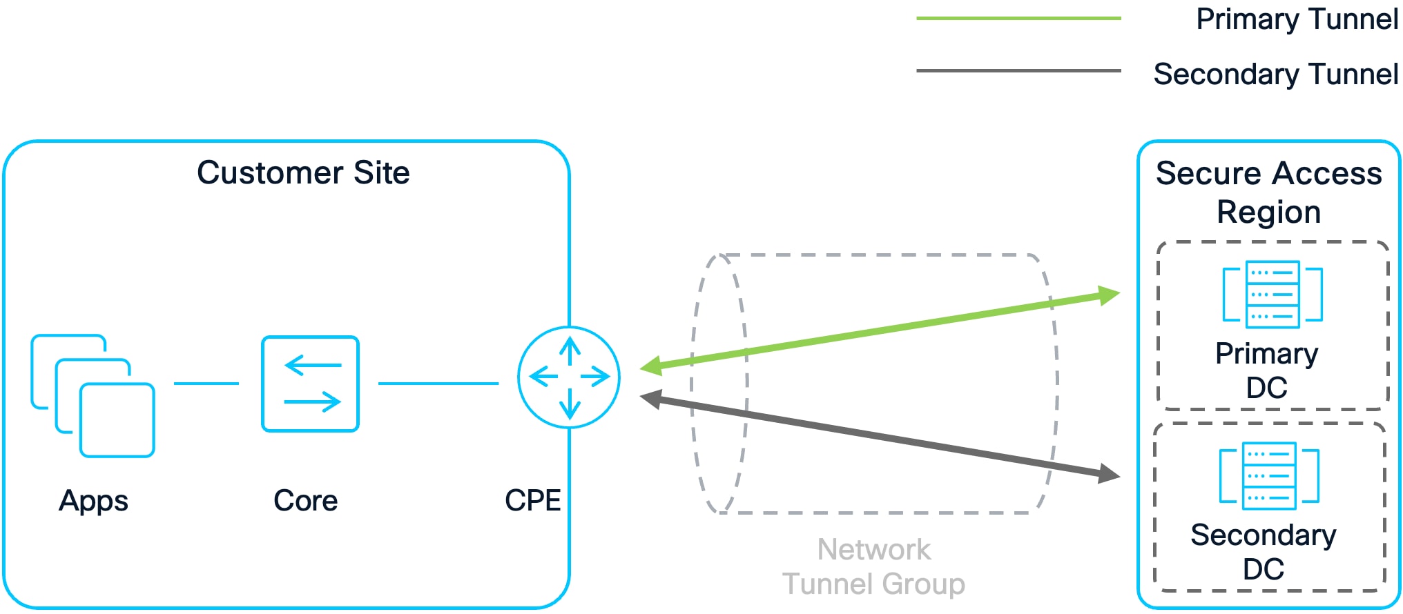
In this configuration, a single CPE device connects to Secure Access Data Centers. With a single device, connections are made to the primary and secondary Secure Access data centers in a region. If the primary Secure Access Data Center fails, connections will failover to the secondary data center. This setup does not protect against failure of the single CPE device, however. For this reason, deploying only a single device for a Secure Access region is not recommended
Active/Standby High Availability (Recommended)
Active/Standby High Availability
Advantages
● No Single Point of Failure: With multiple CPE devices, if the primary device fails, the secondary (standby) device automatically assumes operations, ensuring continuous service availability.
● Simplified Deployment and Management: Only one CPE device handles traffic at any given time, simplifying routing and troubleshooting. The standby device becomes active only during a failover event.
Disadvantages
● Higher Cost: Deploying multiple devices increases hardware, maintenance, and support costs compared to a single-device solution.
● Increased Complexity: Compared to Single Device setup, additional configuration and management are required to keep multiple devices synchronized and ready for failover.
● Resource Underutilization: The standby CPE remains idle during normal operation, leading to inefficient use of hardware resources.
● Limited Scalability: Since only one CPE is active at a time, overall capacity is limited to the specifications of a single device.
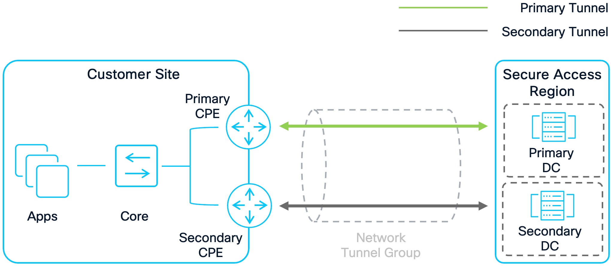
In an Active/Standby setup, one CPE device is active, while the other serves as standby. The Primary CPE connects to the primary Secure Access data center while the secondary CPE establishes a connection with the secondary Secure Access data center in a region. Traffic is sent and forwarded from the primary CPE while the standby CPE is not utilized. If the primary CPE fails, the standby CPE will become active, and traffic will pass through it instead. Failover to the CPE is dependent upon the routing configuration. Secure Access supports static and BGP routing. BGP routing is recommended. To implement Active/Standby with CPE devices using BGP, advertise routes from your Active device with a shorter AS path length. For example, an AS Path Length of 1 for routes coming from the Active device and 2 for routes coming from the Standby device.
Active/Active High Availability (Recommended)
Active/Active High Availability
Advantages
● No Single Point of Failure: With multiple CPE devices operating simultaneously, if one device fails, the remaining device(s) can continue handling traffic, ensuring high availability. Ensure that if all but one CPE device fails, that the remaining CPE has the capacity to handle the full load.
● Improved Scalability: Multiple devices share the traffic load, allowing for greater throughput and better utilization of resources compared to a single device or Active/Standby configuration.
Disadvantages
● Higher Cost: Increased hardware, operational, and maintenance costs result from deploying and maintaining multiple devices.
● Increased Complexity: Traffic must be balanced across all active CPE devices, requiring sophisticated configuration, monitoring, and management to prevent imbalances and ensure optimal performance.
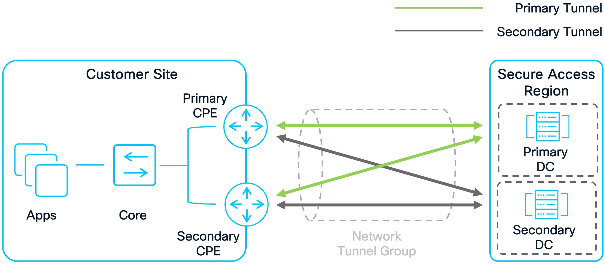
In an Active/Active configuration, both CPEs receive and forward traffic ensuring the resources on both devices are utilized. Both devices establish a connection to the primary and secondary Secure Access data centers in a region. If one device fails, the other will continue to route traffic to its destination. Traffic for a destination may leave either device depending on the load balancing algorithm potentially leading to asymmetric traffic through these devices. It is important to account for this in the customer environment. BGP is recommended; to accomplish Active/Active with CPE devices using BGP, use the same AS path length for all routes advertised by both devices.
Cisco Secure Access supports static routing and BGP routing when establishing connections to SD-WAN routers. While Static routing may be suitable for smaller organizations or testing scenarios, BGP is recommended for most deployments due to its scalability, faster failover, and support for features such as Multi-Region Backhaul (MRB) (discussed later in this guide). BGP eliminates the need to manually configure large numbers of static routes and provides dynamic route updates. When configuring BGP on the CPE the following configurations are suggested:
● Choose an AS number in the range 64513–65534. Do not use AS number 64512 as this is reserved for Secure Access
● Use the local router gateway address as the BGP identifier (Router ID). Do not use an identifier in the 169.254.0.0/24 subnet
● Use a tunnel IP address within the subnet 169.254.0.x/30 if possible. Doing this will simplify the routing configuration on the CPE since the Secure Access BGP peers also utilize this subnet.
● Secure Access has methods of preventing asymmetric routing when a resource is available at multiple customer sites typically through a data center interconnect (DCI).Routes and priorities learned from the Secure Access cloud must be preserved in the customer's DCI networks. This may be accomplished through route transformations or other configurations depending on the routing platform and chosen protocols. For more information, review the Deep Dive section below.
For additional guidance, refer to the Cisco documentation on Dynamic Routing with BGP and Static Routing.
Equal Cost Multi-Path (ECMP) Load Balancing
At the time of publication, Secure Access supports up to 1 Gbps per tunnel to a CPE. If greater throughput is needed to or from a site, multiple tunnels can be established to Secure Access Data centers. On supported CPE devices, up to 10 tunnels can be established to the Primary Secure Access DC and up to 10 tunnels can be established to the Secondary Secure Access DC. This allows for a total throughput of 10 Gbps per Network Tunnel Group. To maximize throughput and redundancy, it is critical to configure routing for ECMP load balancing across these tunnels.
It is also important to make sure that the same number of primary and secondary tunnels are configured when doing ECMP load balancing. For example, when configuring ECMP with 4 primary tunnels, ensure 4 secondary tunnels are created as well. This approach guarantees equivalent throughput during failover scenarios.
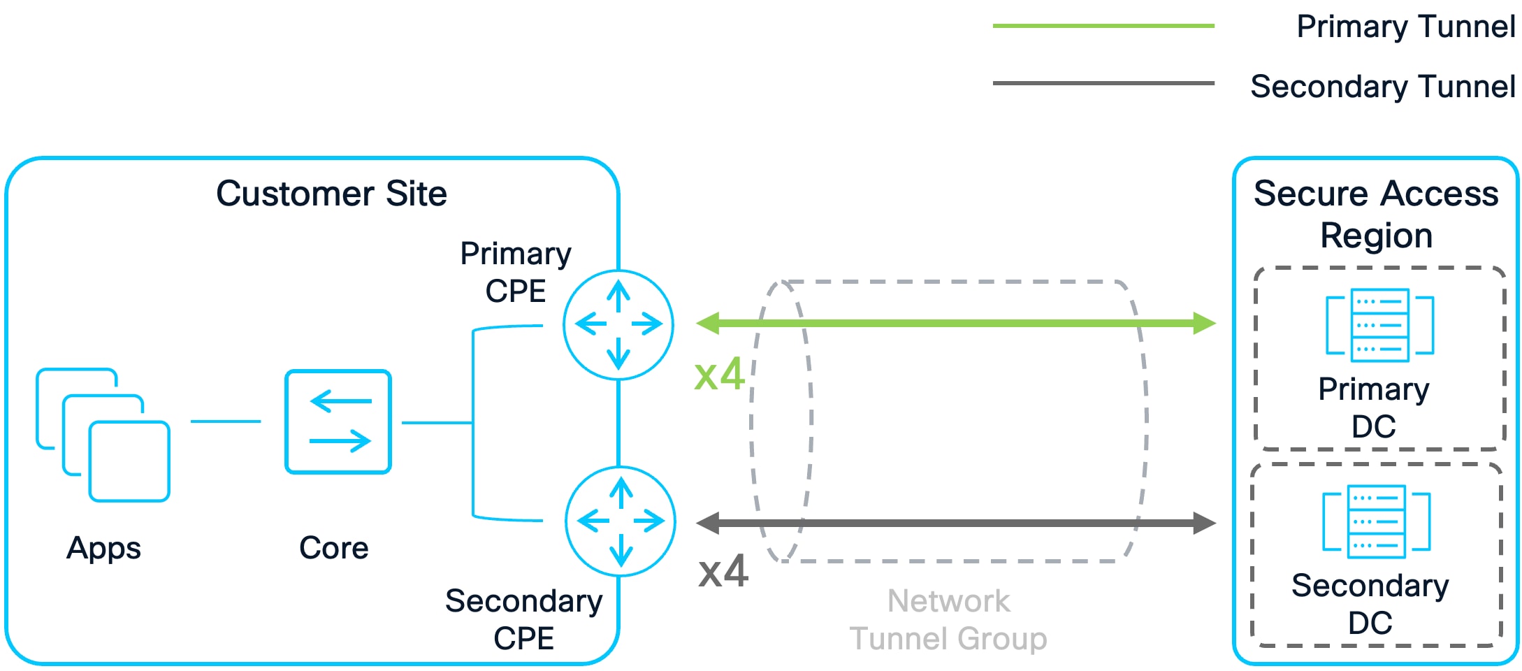
ECMP Load Balancing with 4 Primary Tunnels and 4 Secondary Tunnels
Trusted Network Detection (TND)
Trusted Network Detection (TND) is a feature within Cisco AnyConnect VPN and ZTNA Secure Client modules that automatically disconnects the VPN tunnel or bypasses ZTNA enforcement when an endpoint is on a trusted network. TND enhances security and user experience for VPN only deployments since it will automatically attempt to connect to Secure Access when the user is on an untrusted network where they would not have access to private resources. It can also be used so that traffic that would normally be sent directly to Secure Access is instead sent out the local adapter when the user is on a secure corporate network. This may be necessary for access to resources such as local printers or other use cases.
TND determines network trust by:
● Checking the DNS domain assigned to a network adapter,
● Checking the DNS servers assigned to a network adapter,
● Validating the certificate of an internal HTTPS server.
Whether VPN or the ZTNA module is used, it is recommended to configure them with TND for the benefits mentioned above. When configuring TND, make sure that the configuration is verified and tested to work as intended on trusted and untrusted networks.
For additional guidance, refer to the Cisco documentation on Trusted Networks for Zero Trust Access Connections for ZTNA based TND and Cisco Secure Client Administrator Guide for VPN based TND.
Deploying the Cisco Secure Client ThousandEyes module on user endpoints and integrating it with Secure Access provides comprehensive visibility into the digital experience of remote and hybrid users. Since many users work from networks outside the organization’s control, it is essential to monitor how these environments can impact application performance and user experience. This proactive monitoring enables IT teams to quickly detect, pinpoint, and resolve performance issues, whether they originate from the user device, local network, internet service provider, Secure Access cloud, or application provider.
To maximize these benefits, it is recommended to install the ThousandEyes module on all user endpoints and configure Experience Insights in Cisco Secure Access to run tests targeting critical resources. Additionally, set the organization’s primary collaboration software as a monitored application to collect relevant performance metrics.
For additional guidance, refer to the Cisco documentation on Experience Insights.
The primary objective of a SASE solution is to provide secure, highly available access to private and public resources. This is achieved through robust cryptographic algorithms and advanced routing technologies that encrypt and forward traffic between Secure Access and customer sites. To optimize routing between Secure Access and customer sites, Cisco Secure Access introduces the Multi-Region Backhaul (MRB) feature. With MRB, customers can connect their entire BGP fabric to Secure Access, allowing them to advertise the same routes in different Secure Access regions. It provides the following three key enhancements:
● Local Regional Preference: If active tunnels in a Network Tunnel Group fail within a region and equivalent routes exist in other regions, Secure Access prioritizes routing traffic to standby tunnels in the same region before considering alternate regions
● AS Path Preservation: Secure Access will honor AS Path Lengths, allowing customers to influence routing to Secure Access within a region using an Active/Active NTG deployments
● Multi-hop Support: External BGP peer sessions can be between CPE devices that are not directly connected, enabling more flexible routing architectures
Secure Access Design Overview
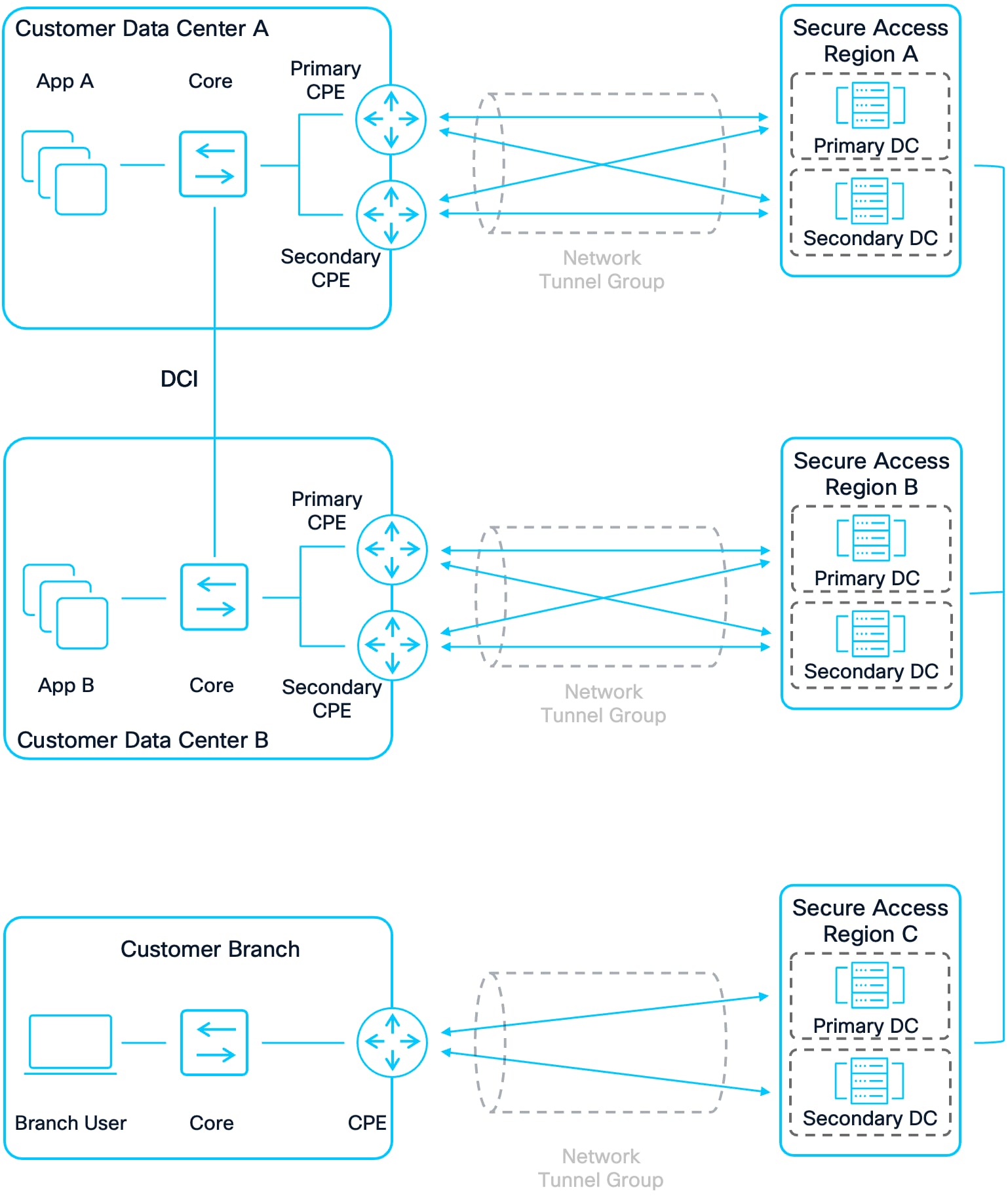
MRB is enabled on a per Network Tunnel Group basis. An NTG is a logical group of IPsec tunnels between the Primary/Secondary Data Centers in a Secure Access region and the CPE devices at a customer’s site. When creating an NTG, the settings for IPsec tunnels and routing (Static or BGP) are configured along with enabling or disabling MRB.
Note: MRB should only be enabled on NTGs at customer sites that advertise the same routes to different Secure Access regions. For example, a customer has two data centers - one geographically located in the western US and the other geographically located in the eastern US. Each customer data center connects to its local Cisco Secure Access region using a Network Tunnel Group (NTG). The data centers have a data center interconnect, allowing applications to be available in both locations.
● If the customer advertises the same application routes from both data centers to their respective Secure Access regions, MRB should be enabled in the NTG.
● If each application is only advertised from one data center, MRB should be disabled.
Additionally, each region determines which Secure Access data center is prioritized using the BGP Multi Exit Discriminator (MED) value. When advertising routes to CPE devices:
● The Primary Secure Access Data Center will use the MED value 0
● The Secondary will use the MED value 1
● The lower MED value is always preferred
In addition to the MRB feature, customers may continue to influence routes advertised to Secure Access using AS Path Length. Within a region, a customer can increase the AS Path Length to provide redundancy across NTGs.
BGP Prefix advertisement with Multi-Region Backhaul
When a VPN User connects to Secure Access, they are assigned an IP address from the IP Pool associated with the Secure Access region. This IP address is used to route their data to private resources within the customer environment. For the customer network to send traffic back to these users, there must be an appropriate route back to the Secure Access Region where the user is connected.
The following diagram illustrates multiple RAVPN users connecting to different Secure Access regions and the process of advertising the RAVPN User routing prefix from Secure Access regions to customer sites.
Note: While the examples focus on a RAVPN user, the user could also be a ZTNA Remote User as well. In this case, the user’s device will come from an address in the 100.64.0.0/10 subnet and a prefix advertised to the CPE device will be a /32. For example, 100.64.0.1/32.
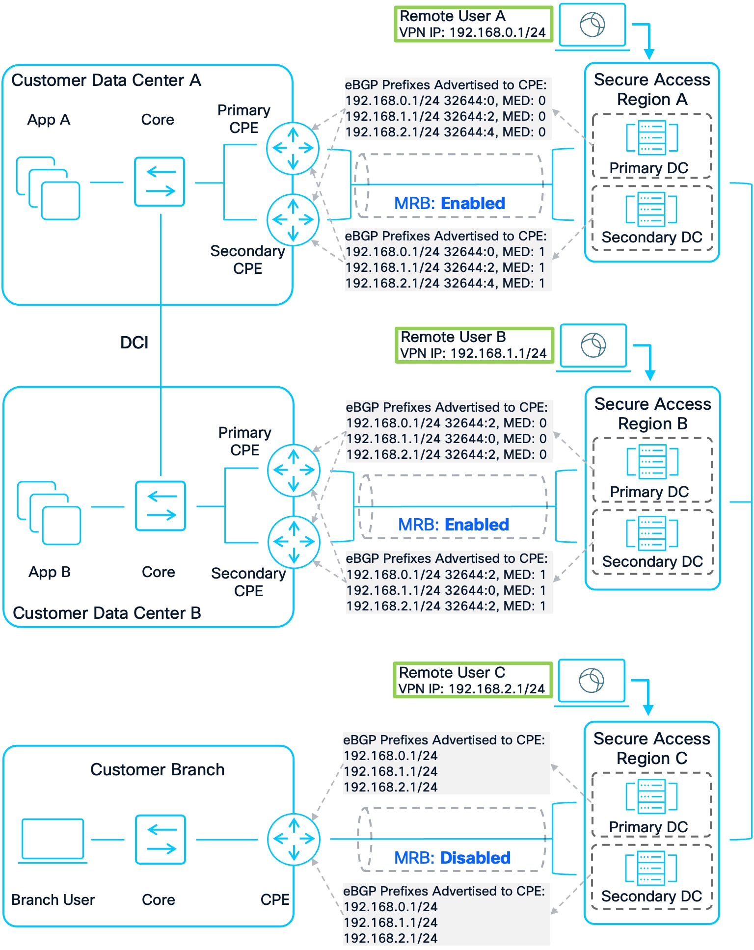
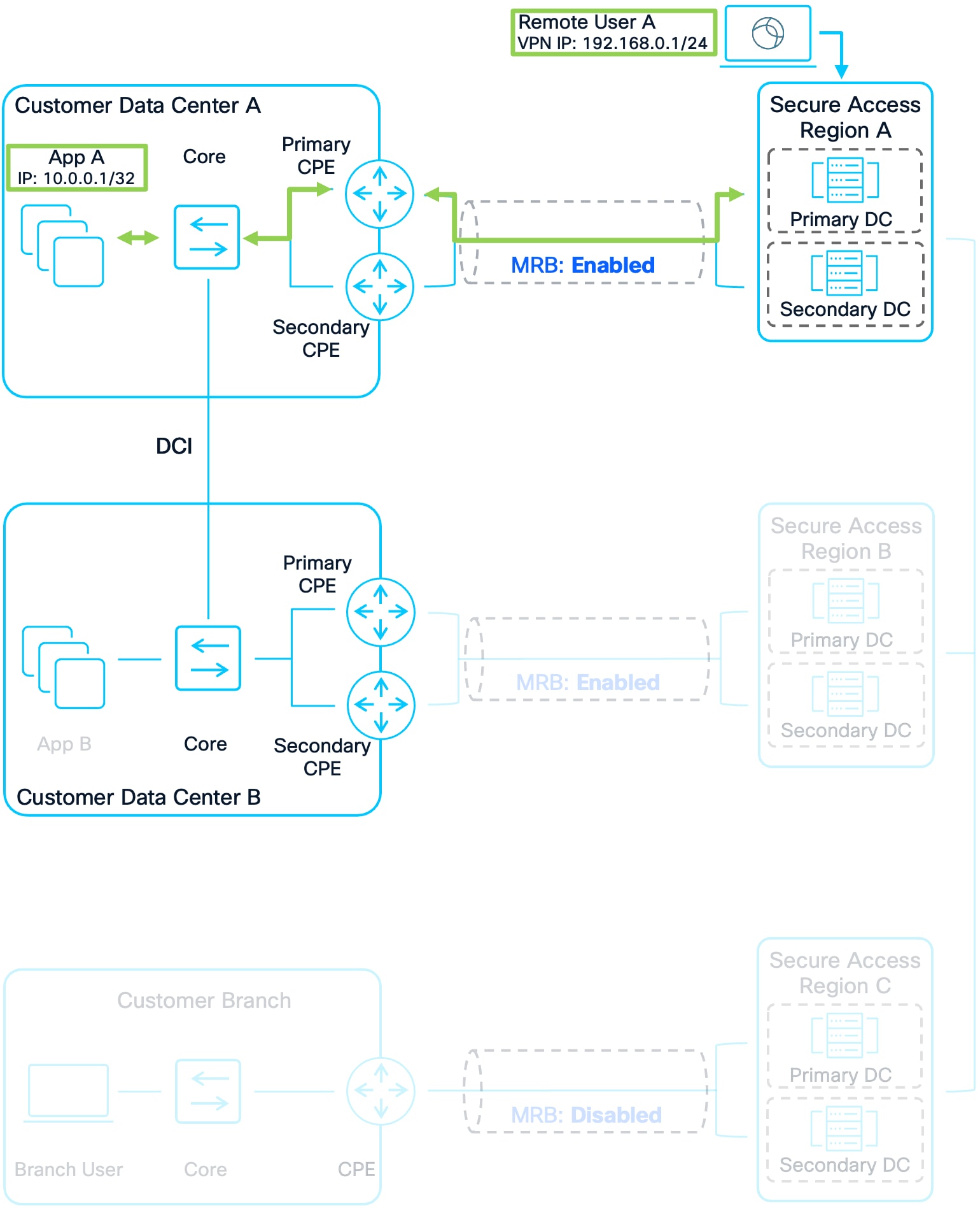
Prefixes Originating from Secure Access to Customer Sites
In this example, several Remote Users connect to different Secure Access regions. The focus is on Remote User A, who connects to Secure Access Region A and is assigned the IP address 192.168.0.1/24. This prefix is advertised to all CPE devices that have established a BGP connection with the Secure Access regions. Any traffic destined for 192.168.0.1/24 and sent to the Secure Access cloud will be internally routed to Region A if it originates from a different region. Multi-Region Backhaul is enabled for the Network Tunnel Groups between Secure Access Region A and Customer DC A, as well as between Secure Access Region B and Customer DC B, but it is disabled for the Customer Branch.
Region A advertises the 192.168.0.1/24 prefix for Remote User A to its connected CPE devices. Since MRB is enabled for the NTG between Region A and Customer DC A, Region A includes a BGP community string with the value 32644:X in the advertisement, where 32644 is the Cisco Secure Access public ASN and X encodes the regional priority. Each prefix is assigned a unique regional priority value, with a lower number indicating a higher preference; because Remote User A is local to Region A, the regional priority is set to 0.
Similarly, MRB is enabled for the NTG between Secure Access Region B and Customer DC B. Since Region B is considered the second closest region for the 192.168.0.1/24 prefix, it advertises this prefix with a community string indicating a regional priority of 2. In contrast, MRB is not enabled for the NTG between Secure Access Region C and Customer Branch, so only the prefix 192.168.0.1/24 is advertised from that location, without any community string.
No two community strings for the same prefix will have the same regional priority value. Additionally, routes and regional priorities learned from the Secure Access cloud must be retained within the customer's Data Center Interconnect (DCI) networks, which may require route transformations or specific configurations depending on the routing platform and protocols used. This approach helps maintain routing symmetry with Secure Access. Finally, if MRB is enabled, the primary Secure Access data center advertises the prefix with a Multi-Exit Discriminator (MED) value of 0, while the secondary data center uses MED: 1, ensuring that the primary data center is preferred for routing whenever possible.
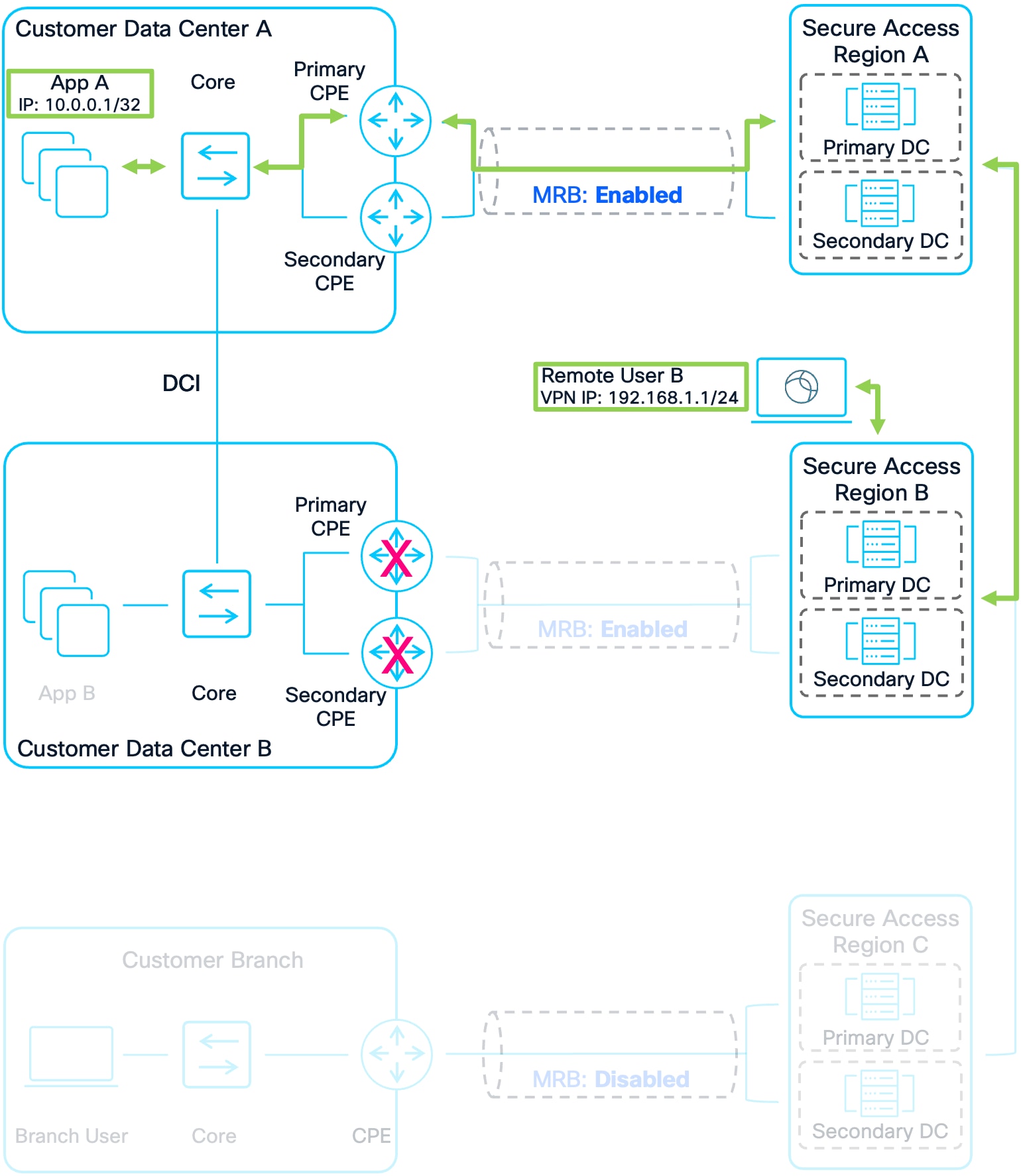
The next diagram illustrates routes advertised from a customer’s network being advertised to other regions. With MRB, Secure Access follows a hot potato routing model: traffic is sent to the customer fabric through the closest Secure Access region.
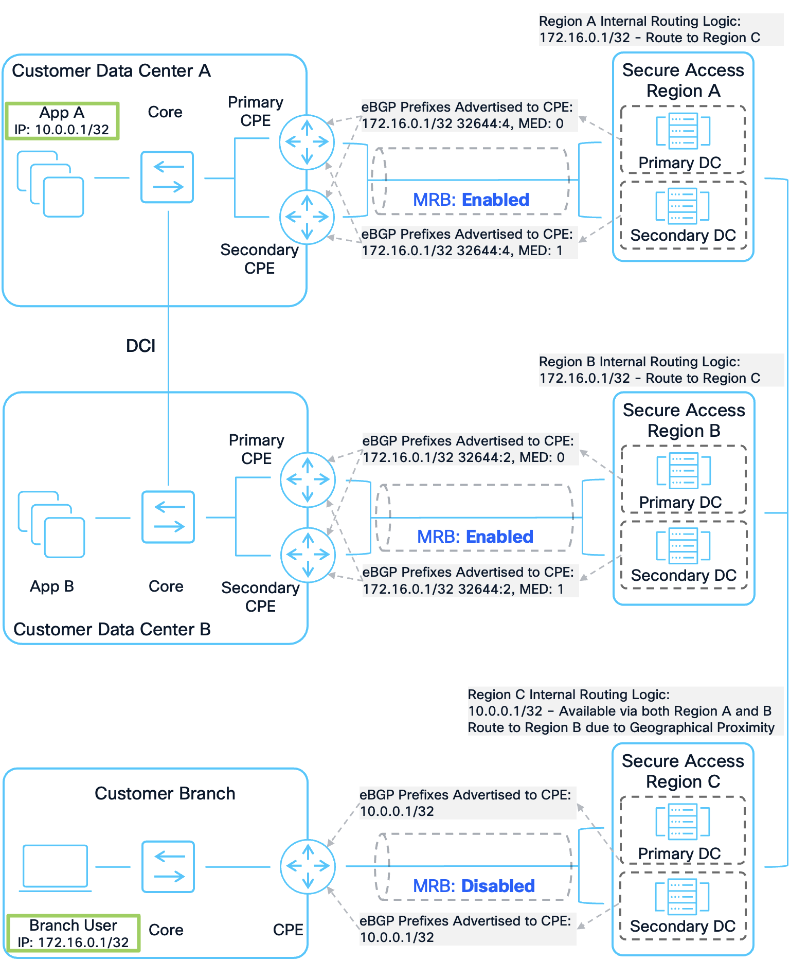
Prefixes Originating from Customer Sites to Other Regions
In this example, the IP address of App A (10.0.0.1/32), which is hosted in Customer Data Center (DC) A, is advertised from the CPE devices at both Customer DC A and Customer DC B to Secure Access Region A and Region B. Because a DCI link connects the two data centers, App A is accessible from both DC A and DC B, and both Region A and Region B install local routes for App A. This allows App A to be accessed directly from either Region A or Region B, without the need to route traffic through a different region. Similarly, the IP address of the Branch User (172.16.0.1/32) at the Customer Branch is advertised to Secure Access Region C from the CPE device at that site, so Region C installs a local route for the Branch User.
Regions A and B then advertise the prefix for App A (10.0.0.1/32) to Region C, while Region C advertises the prefix for the Branch User (172.16.0.1/32) to Regions A and B. Multi-Region Backhaul is enabled for the Network Tunnel Groups (NTGs) between Secure Access Region A and Customer DC A, as well as between Secure Access Region B and Customer DC B, but it is disabled for the Customer Branch. When Region A advertises the 172.16.0.1/32 prefix for the Branch User to its connected CPE devices, it includes a BGP community string with the value 32644:X, where 32644 is the Cisco Secure Access public ASN and X indicates the regional priority, because MRB is enabled on the NTG between Region A and DC A. In this scenario, Region B is geographically closest to Region C, followed by Region A, so the regional priority value (X) for the prefix from Region A is set to 4.
MRB is also enabled on the NTG between Secure Access Region B and Customer DC B. Since Region B is the closest region to Region C, Region B advertises the 172.16.0.1/32 prefix with a BGP community string indicating a regional priority of 2. In contrast, when Region C advertises a route for App A to its connected CPE devices at the Customer Branch, no community string is included because MRB is not enabled there.
Internally, Region C receives two routes for App A—one from Region A and one from Region B. Since Region B is considered geographically closer, Region C will prefer the route through Region B.
For all prefixes advertised to CPE devices, if MRB is enabled, the primary Secure Access data center uses a Multi-Exit Discriminator (MED) value of 0, while the secondary data center uses MED: 1. This ensures that, under normal circumstances, the primary data center is preferred. If the primary data center in a region or the primary tunnels in the NTG become unavailable, the secondary data center prefix will be preferred.
The following examples show how Multi-Region Backhaul affects how BGP prefixes are advertised and the resulting traffic flow.
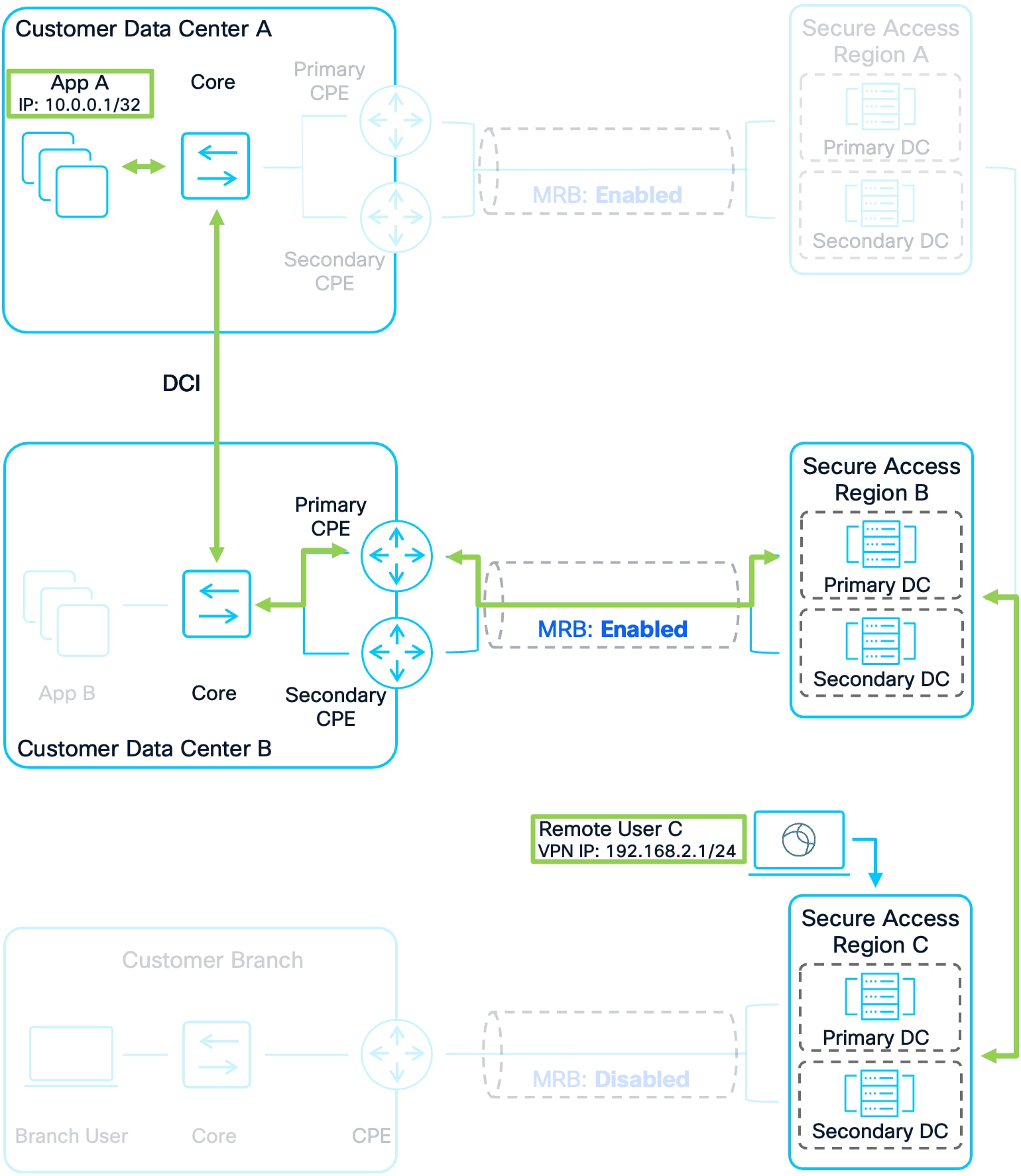
Example 1: Remote User C to Apps
1. Remote User C connects to Secure Access Region C. Their IP address prefix is advertised to other Secure Access Regions and Customer Sites allowing other users and application traffic to route to them.
2. Remote User C attempts to access App A in Customer DC A. Region C has a route for this application that was advertised by Region A and Region B earlier. Region C prefers Region B because it is closer geographically.
3. Region C forwards the packet to Region B. Region B routes the traffic over the established tunnels to the CPE devices. The customer’s network then forwards the packet over the DCI to App A in Customer DC A
4. Customer DC A’s infrastructure will have two routes for Remote User C because Region C advertised the prefix to both regions. It is important however that the traffic is not sent to Region A as this would result in asymmetric routing. Region A and Region B included a regional priority value in the community string. Due to this, sending the return traffic to Region B is preferred because Region B sent a community string with a lower regional priority (2) compared to Region A’s (4). See Figure 11 for the routing schematic.
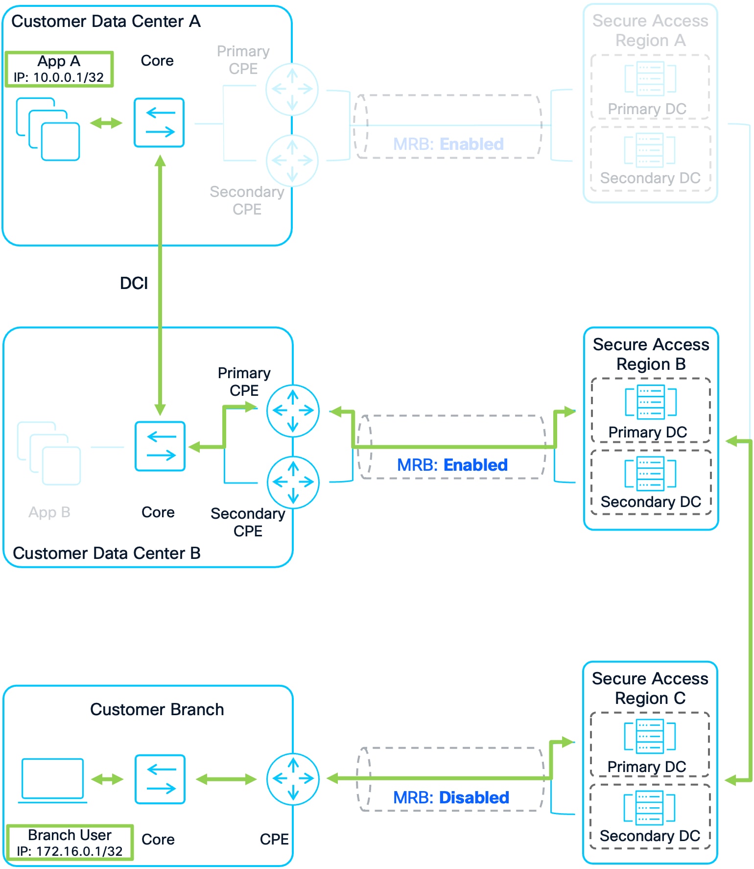
Example 2: Branch User C to Apps
1. A Branch User in Customer Branch is attempting to access App A in Customer DC A. The user’s prefix has already been advertised to Secure Access Region C, which has advertised it to Region A and B, which in turn have advertised it to Customer DCs A and B (See Figure 12). This allows for bidirectional traffic between Branch users and users/applications at other sites.
2. Branch User sends traffic to App A in Customer DC A. Region C has a route for App A that was advertised by Region A and Region B earlier. Region C prefers Region B because it is closer geographically.
3. Region C forwards the packet to Region B. Region B routes the traffic over the established tunnels to the CPE devices. The customer’s network then forwards the packet over the DCI to App A in Customer DC A
4. Customer DC A’s infrastructure will have two routes for Branch User because Region C advertised the prefix to both regions. It is important however that the traffic is not sent to Region A as this would result in asymmetric routing. Region A and Region B included a regional priority value in the community string. Due to this, sending the return traffic to Region B is preferred because Region B sent a community string with a lower regional priority (2) compared to Region A’s (4). See Figure 11 for the routing schematic.
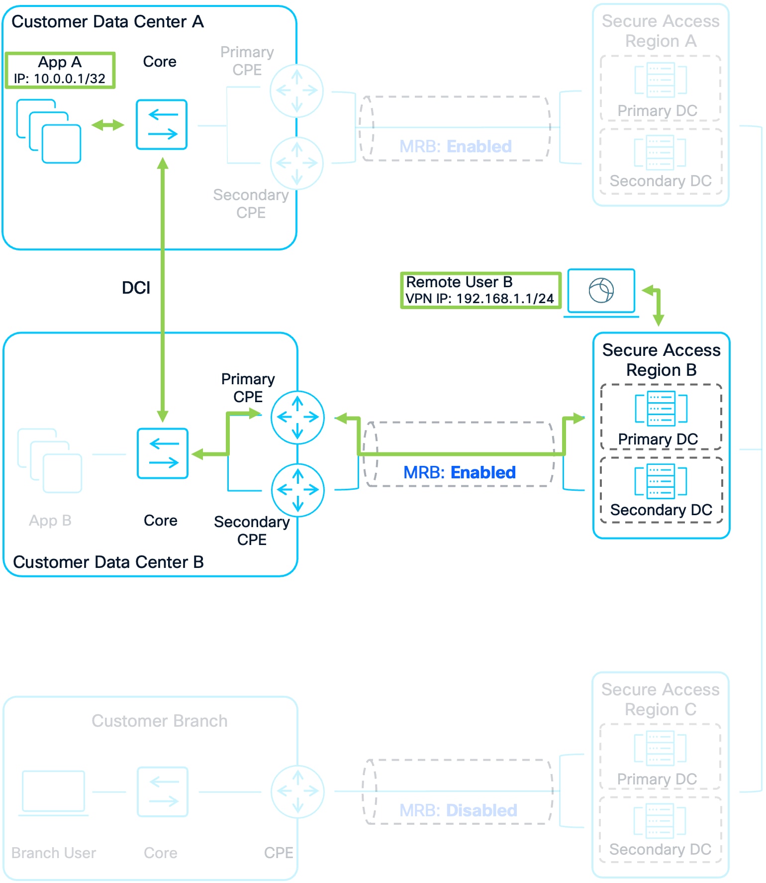
Example 3: Remote User B to Apps
1. Remote User B connects to Secure Access Region B. Their IP address prefix is advertised to other Secure Access Regions and Customer Sites allowing other users and application traffic to route to them.
2. Remote User B attempts to send traffic to App A in Customer DC A. Region B has a route for App A that was advertised by Region A and by the CPE devices in Customer DC B earlier. Region B prefers to send the traffic to Customer DC B because it has a local route.
3. Region B routes the traffic over the established tunnels to the CPE devices. The customer’s network then forwards the packet over the DCI to App A in Customer DC A
4. Customer DC A’s infrastructure will have two routes for Remote User B because both Region B and Region A advertised the prefix for Remote User B. Region B advertised it because Remote User B is directly connected to it. Region A advertised it because it received the advertisement from Region B. It is important however that the traffic is not sent to Region A as this would result in asymmetric routing. Region A and Region B included a regional priority value in the community string. Due to this, sending the return traffic to Region B is preferred because Region B sent a community string with a lower regional priority (0) compared to Region A’s (2). See Figure 11 for the routing schematic.
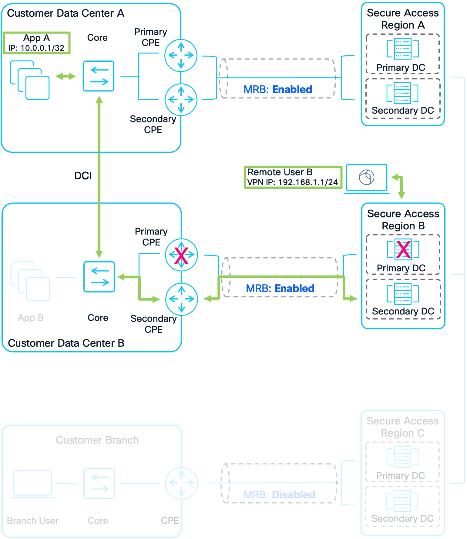
Example 4: Remote User B to Apps Via Secondary CPE Device Due to Failure
1. Remote User B connects to Secure Access Region B. Their IP address prefix is advertised to other Secure Access Regions and Customer Sites allowing other users and application traffic to route to them.
2. Remote User B attempts to send traffic to App A in Customer DC A. The primary NTG is down because either the Secure Access Primary DC is down or the Customer’s Primary CPE at their DC is down (in an Active/Standby Deployment). Region B has a route for App A that was advertised by Region A and by the secondary CPE device in Customer DC B. Region B prefers to send the traffic to Customer DC B because it has a local route.
3. Region B routes the traffic over the established secondary tunnels to the CPE device. The customer’s network then forwards the packet over the DCI to App A in Customer DC A
4. Customer DC A’s infrastructure will have two routes for Remote User B because both Region B and Region A advertised the prefix for Remote User B. Region B advertised it because Remote User B is directly connected to it. Region A advertised it because it received the advertisement from Region B. It is important however that the traffic is not sent to Region A as this would result in asymmetric routing. Region A and Region B included a regional priority value in the community string. Due to this, sending the return traffic to Region B is preferred because Region B sent a community string with a lower regional priority (0) compared to Region A’s (2). See Figure 11 for the routing schematic.
5. When the return packet reaches the CPE devices in Customer DC B, it sends traffic to Region B Secondary DC which provided a route for Remote User B with a MED of 1. This is because the Primary DC is down and so the higher priority route with MED: 0 no longer exists.
Example 5: Remote User B to Apps Via Region A Due to Failure
1. Remote User B connects to Secure Access Region B. Their IP Address Prefix is advertised to other Secure Access Regions and Customer Sites allowing other users and application traffic to route to them.
2. Remote User B attempts to send traffic to App A in Customer DC A. Region B has a prefix for App A that was advertised by Region A. It does not have a prefix from the CPE devices in Customer DC B because the tunnels to both the Primary and Secondary CPE devices are down. Because of this, Region B only has a single route for App A.
3. Region B forwards the packet to Region A. Region A routes the traffic over the established tunnels to the CPE devices in Customer DC A. The customer’s network then forwards the packet to App A.
4. Unlike the previous examples, Customer DC A’s infrastructure will only have a single route to Remote User B because only Region A is advertising the prefix for Remote User B. The tunnels between Region B and the CPE devices in Customer DC B are down and so there is no route to Remote User B from Customer DC B. Return traffic is sent to Region A.
Example 6: Remote User A to Apps
1. Remote User A connects to Secure Access Region A. Their IP address prefix is advertised to other Secure Access Regions and Customer Sites allowing other user and application traffic to route to them.
2. Remote User A attempts to send traffic to App A in Customer DC A. Region A has a route for App A that was advertised by the CPE devices in Customer DC A and Region B earlier. Region A prefers to send the traffic to Customer DC A because it has a local route.
3. Region A routes the traffic over the established tunnels to the CPE devices. The customer’s network in Customer DC A then forwards the packet to App A.
4. Customer DC A’s infrastructure will have two routes for Remote User A because both Region A and Region B advertised the prefix for Remote User A. Region A advertised it because Remote User A is directly connected to it. Region B advertised it because it received the advertisement from Region A. It is important however that the traffic is not sent to Region B as this would result in asymmetric routing. Region A and Region B included a regional priority value in the community string. Due to this, sending the return traffic to Region A is preferred because Region A sent a community string with a lower regional priority (0) compared to Region B’s (2). See Figure 11 for the routing schematic.
| Software |
Version |
| AI |
Artificial Intelligence
|
| AS |
Autonomous System
|
| ASN |
Autonomous System Number
|
| BGP |
Border Gateway Protocol
|
| CASB |
Cloud Access Security Broker
|
| CPE |
Customer Premises Equipment
|
| CSA |
Cisco Secure Access
|
| DC |
Data Center
|
| DCI |
Data Center Interconnect
|
| DHCP |
Dynamic Host Configuration Protocol
|
| DIA |
Direct Internet Access
|
| DLP |
Data Loss Prevention
|
| DNS |
Domain Name Resolution
|
| DTLS |
Datagram Transport Layer Security
|
| eBGP |
Exterior Border Gateway Protocol
|
| ECMP |
Equal Cost Multi-Path
|
| EIGRP |
Enhanced Interior Gateway Routing Protocol
|
| FWaaS |
Firewall as a Service
|
| Gbps |
Gigabits Per Second
|
| HA |
High Availability
|
| HTTP |
Hypertext Transfer Protocol
|
| iBGP |
Interior Border Gateway Protocol
|
| ICMP |
Internet Control Message Protocol
|
| IKEv2 |
Internet Key Exchange Version 2
|
| IoT |
Internet Of Things
|
| IP |
Internet Protocol
|
| IPS |
Intusion Prevention System
|
| IPsec |
Internet Protocol Security
|
| MED |
Multi Exit Discriminator
|
| MRB |
Multi-Region Backhaul
|
| NGFW |
Next Generation Firewall
|
| NTG |
Network Tunnel Group
|
| PAC |
Proxy Auto-Config
|
| RAVPN |
Remote Access Virtual Private Network
|
| RBI |
Remote Browser Isolation
|
| RDP |
Remote Desktop Protocol
|
| SaaS |
Software as a Service
|
| SASE |
Secure Access Service Edge
|
| SD-WAN |
Software Defined Wide Area Network
|
| SIA |
Secure Internet Access
|
| SPA |
Secure Private Access
|
| SSE |
Security Service Edge
|
| SSH |
Secure Shell
|
| SWG |
Secure Web Gateway
|
| TCP |
Transmission Control Protocol
|
| TLS |
Transport Layer Security
|
| UDP |
User Datagram Protocol
|
| UPN |
User Principal Name
|
| VA |
Virtual Appliance
|
| VPN |
Virtual Private Network
|
| VPNaaS |
Virtual Private Network as a Service
|
| WAN |
Wide Area Network
|
| ZTA |
Zero Trust Access
|
| ZTNA |
Zero Trust Network Access
|
● Cisco Secure Access Overview
● Cisco Secure Access Resources
● Cisco Secure Access Documentation
● Cisco Secure Client Administrator Guide
● Cisco Meraki SD-WAN Overview
● Cisco Catalyst SD-WAN Overview
● Cisco Secure Firewall SD-WAN Overview