Use this procedure to install and deploy geo-redundant Cisco Optical Network Controller. It helps you complete the related installation workflow and confirm the deployment state before continuing.
Deploy the Cisco Optical Network Controller OVA for each supercluster node. Deploy a separate OVA for every node in vCenter.
For background and deployment considerations, see Geo-redundant deployment overview.
Use the same template values across all nodes and adjust only node-specific settings. Assign consistent names and configure network mappings for every node.
Before you begin
Review prerequisites in Geo-redundant deployment prerequisites.
Follow these steps to deploy the OVA for each supercluster node.
Procedure
-
In the Select a compute resource screen, select the destination for the VM. In the Review details screen, verify the template details and click Next.
Figure 2. Select a Compute Resource 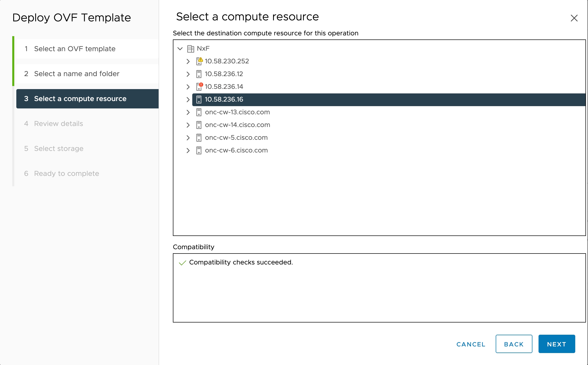
The compatibility check proceeds until it completes successfully.
Figure 3. Review Details Figure 4. Review Details 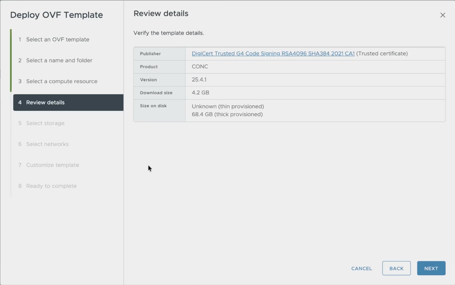 The Publisher field shows the trusted publisher information. For example, DigiCert Trusted G4 Code Signing RSA4096 SHA384 2021 CA1 (Trusted certificate).
 -
In the Select storage screen, select the virtual disk format according to your requirements. VM Storage Policy is set as Datastore Default and click Next. Select the virtual disk format as Thin Provision.
Figure 5. Select Storage 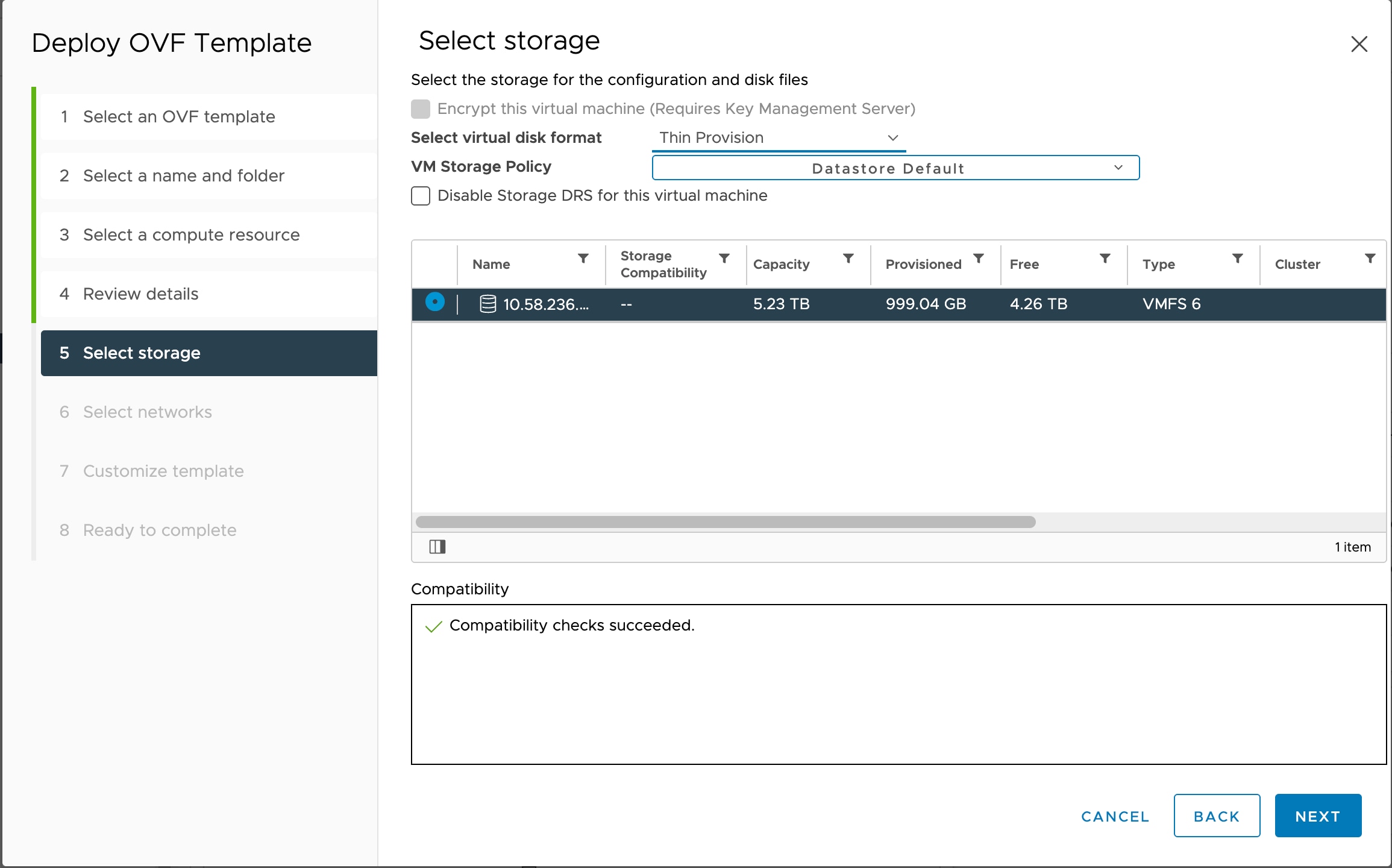
-
In the Select networks screen, select the Control Plane, Eastbound, and Northbound networks you created for each VM and click Next.
Figure 6. Select Networks 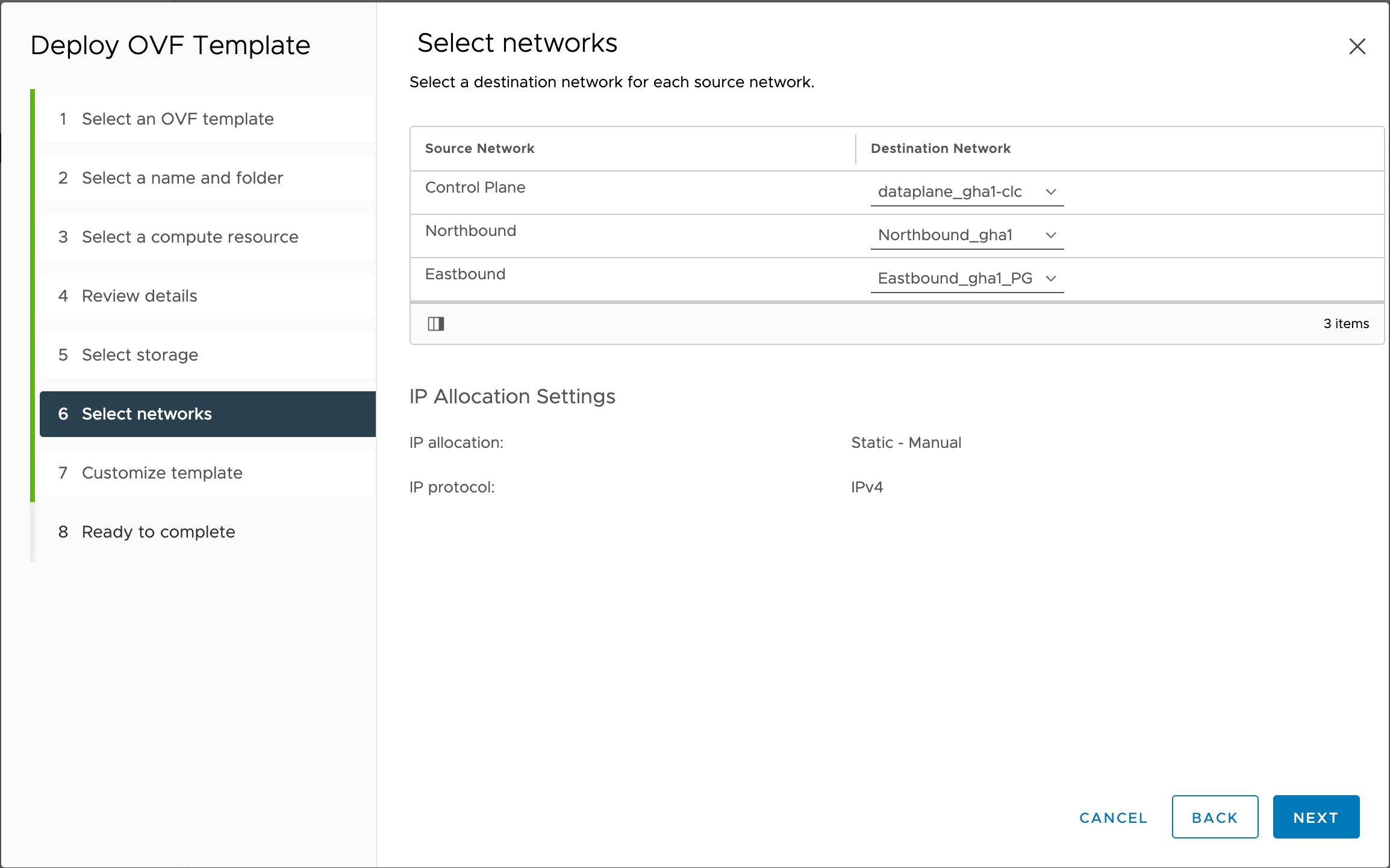
-
In the Customize template screen, set the values using the following table as a guideline.
Figure 7. Customize Template 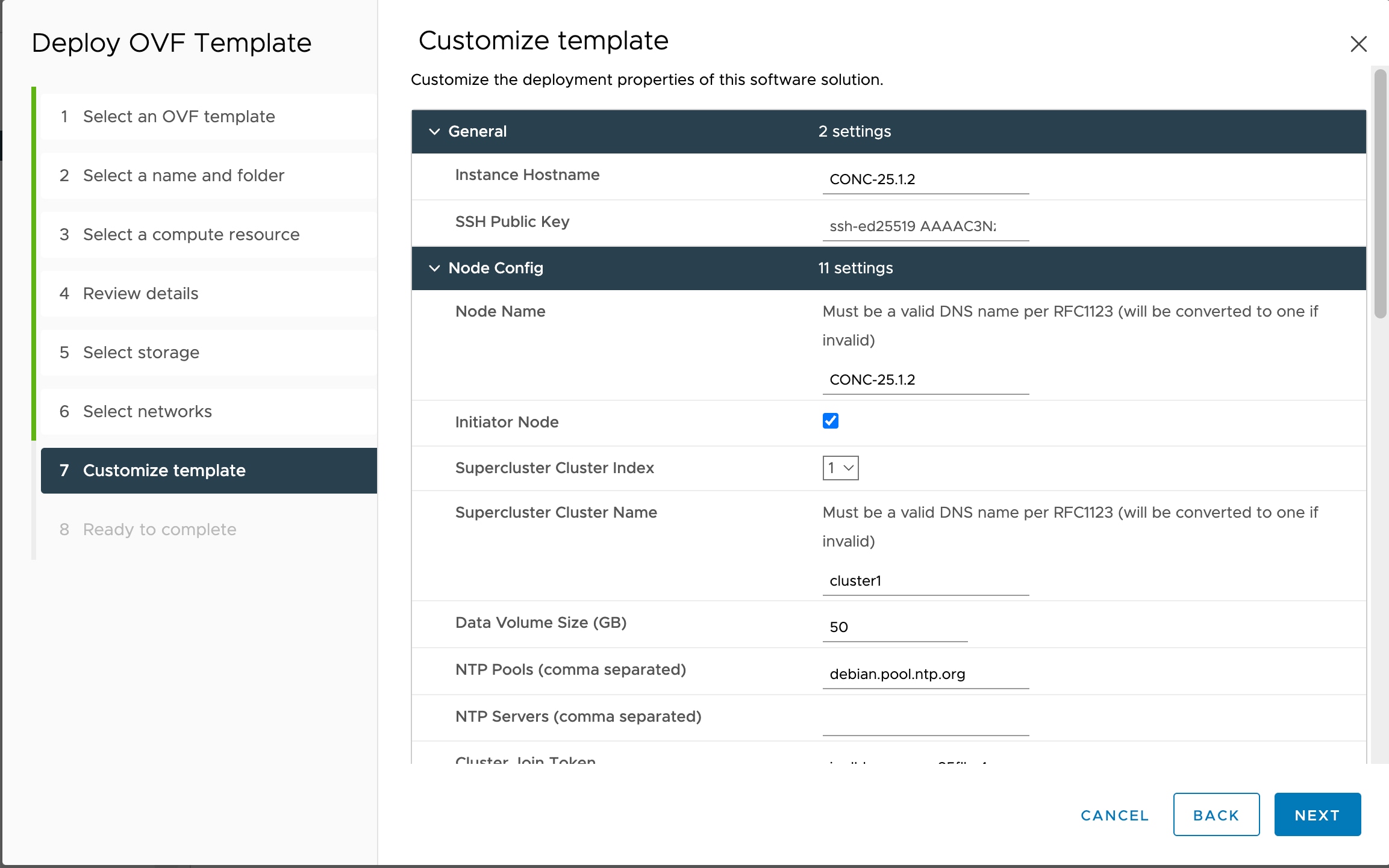
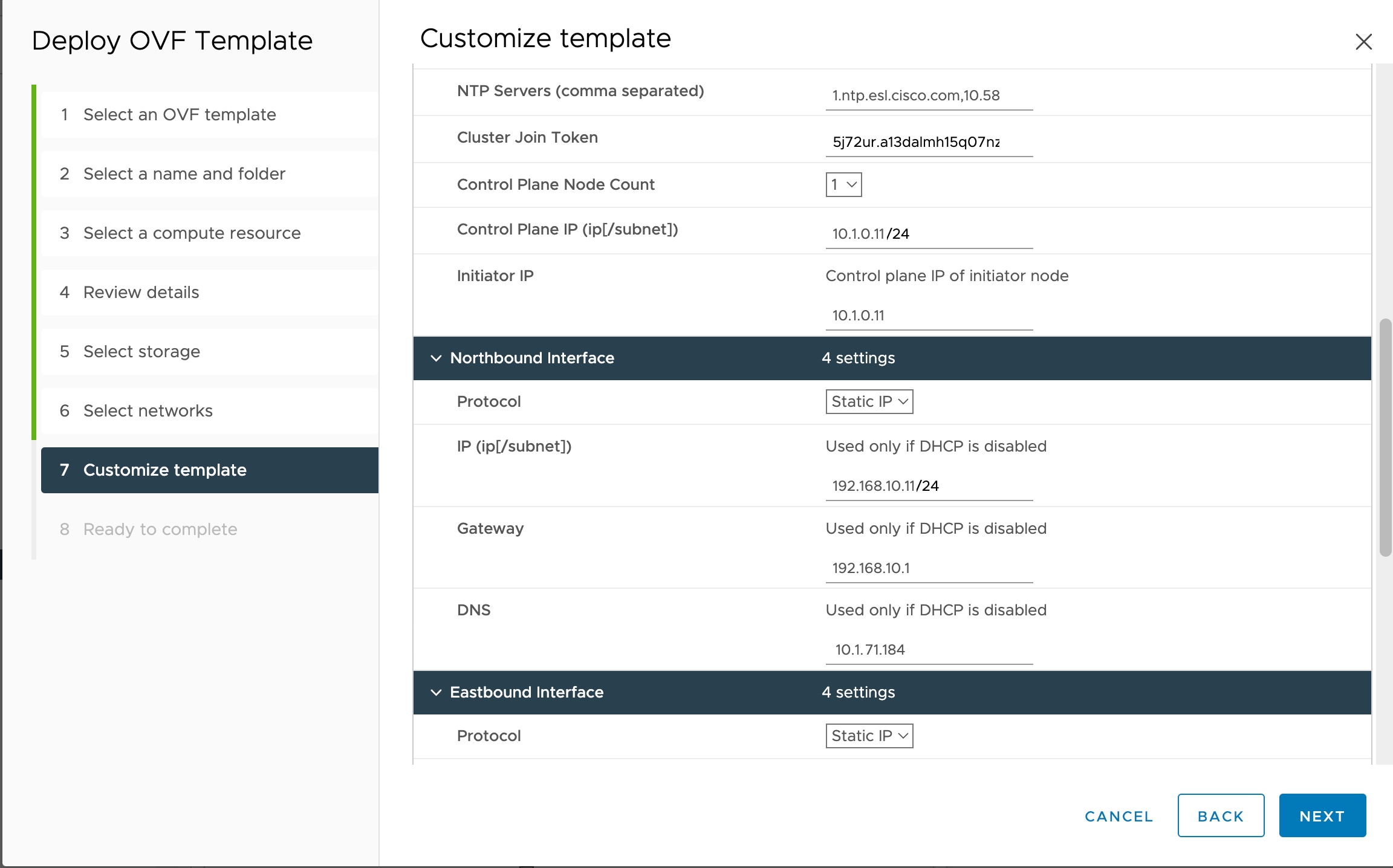
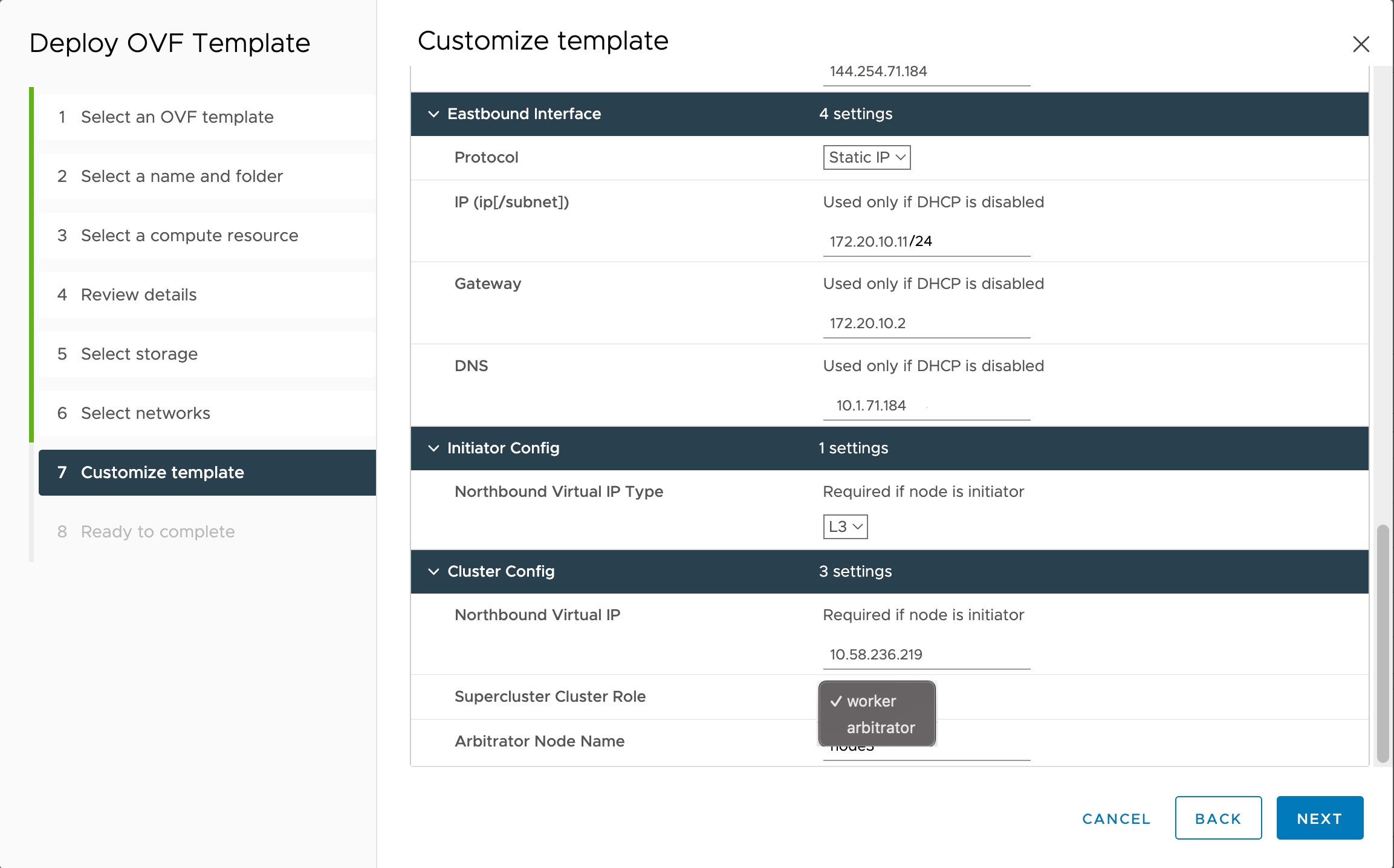
For the arbitrator node, choose arbitrator as the Supercluster Cluster Role.
Table 1. Customize Template Key Values General
Instance Hostname <instance-name> Must be a valid DNS name per RFC1123.1.2.4.
-
Contain at most 63 characters.
-
Contain only lowercase alphanumeric characters or '-'
-
Start with an alphanumeric character.
-
End with an alphanumeric character.
SSH Public Key <ssh-public-key>. Used for SSH access that allows you to connect to the instances securely without the need to manage credentials for multiple instances. SSH public key must be a ed25519 key. See SSH Key Generation.
Node Config
Node Name Use the same name as Instance Hostname
Initiator Node Select the check box Supercluster Cluster Index Set to 1 (active cluster), 2 (standby cluster), or 3 (arbitrator).
Supercluster Cluster Name Set to cluster1 (active cluster), cluster2 (standby cluster), or cluster3 (arbitrator).
Data Volume Size (GB) Configure data volume according to the VM profile.
NTP Pools (comma separated) (Optional) A comma-separated list of the NTP pools. For example, debian.pool.ntp.org
NTP Servers (comma separated) A comma-separated list of the NTP servers.
Cluster Join Token Autogenerated value. Leave as is.
Control Plane Node Count 1 Control Plane IP (ip[/subnet]) <Private IP for the Instance> Control Plane Network Initiator IP <Same IP as Control Plane> Control Plane Network Northbound Interface
Protocol Static IP IP (ip[/subnet]) - if not using DHCP <Public IP for the Instance> Northbound Network Gateway - if not using DHCP <Gateway IP for the Instance> Northbound Network DNS DNS Server IP Eastbound Interface
Protocol Static IP IP (ip[/subnet]) - if not using DHCP < IP for the Instance> Eastbound Network
Gateway - if not using DHCP <Gateway IP for the Network> Eastbound Network DNS DNS Server IP Initiator Config
Northbound Virtual IP Type L3 Cluster Config
Northbound Virtual IP Virtual IP for the SuperCluster Supercluster Cluster Role worker for primary and secondary nodes
arbitrator for arbitrator node
Arbitrator Node Name a unique node name. -
The arbitrator node name must not the same as any node in the supercluster. This field must not be the same as the node name of the arbitrator node either.
-
The arbitrator node name must be the same across all nodes in the supercluster.
Do not configure the Northbound and Eastbound networks in the same subnet or VLAN segment. Use separate subnets and VLAN segments for these networks.
-
-
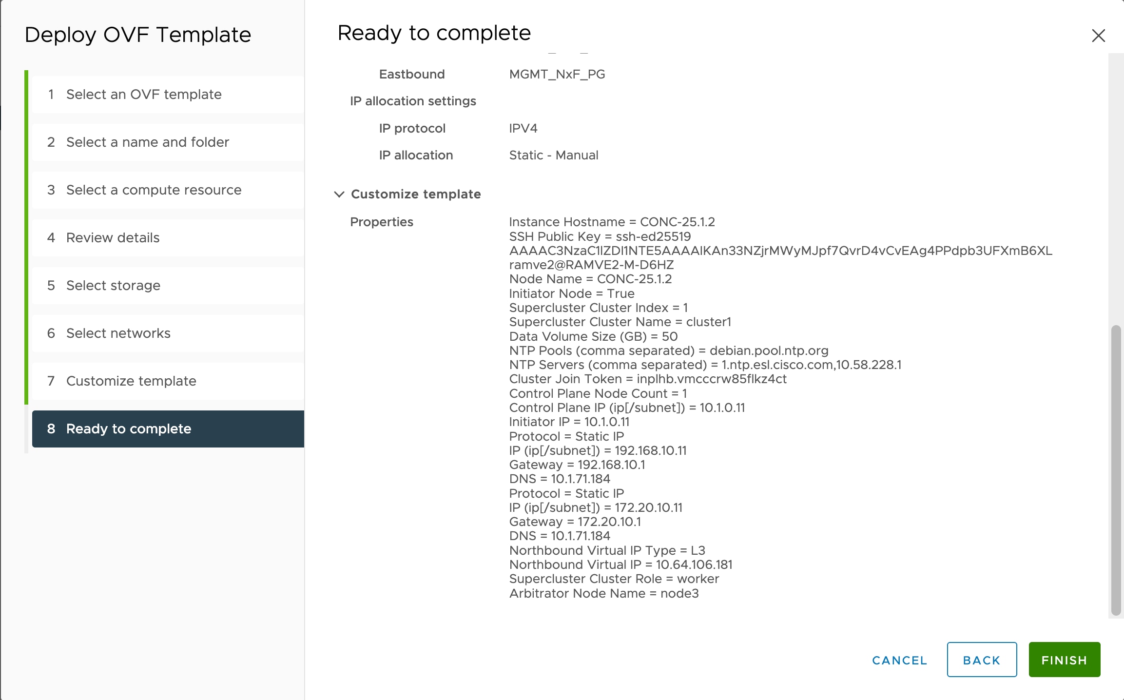
In Review the details screen, review all your selections and click Finish. To check or change any properties from the review screen, before clicking Finish, click BACK to return to the Customize template screen.
Figure 8. Ready to Complete 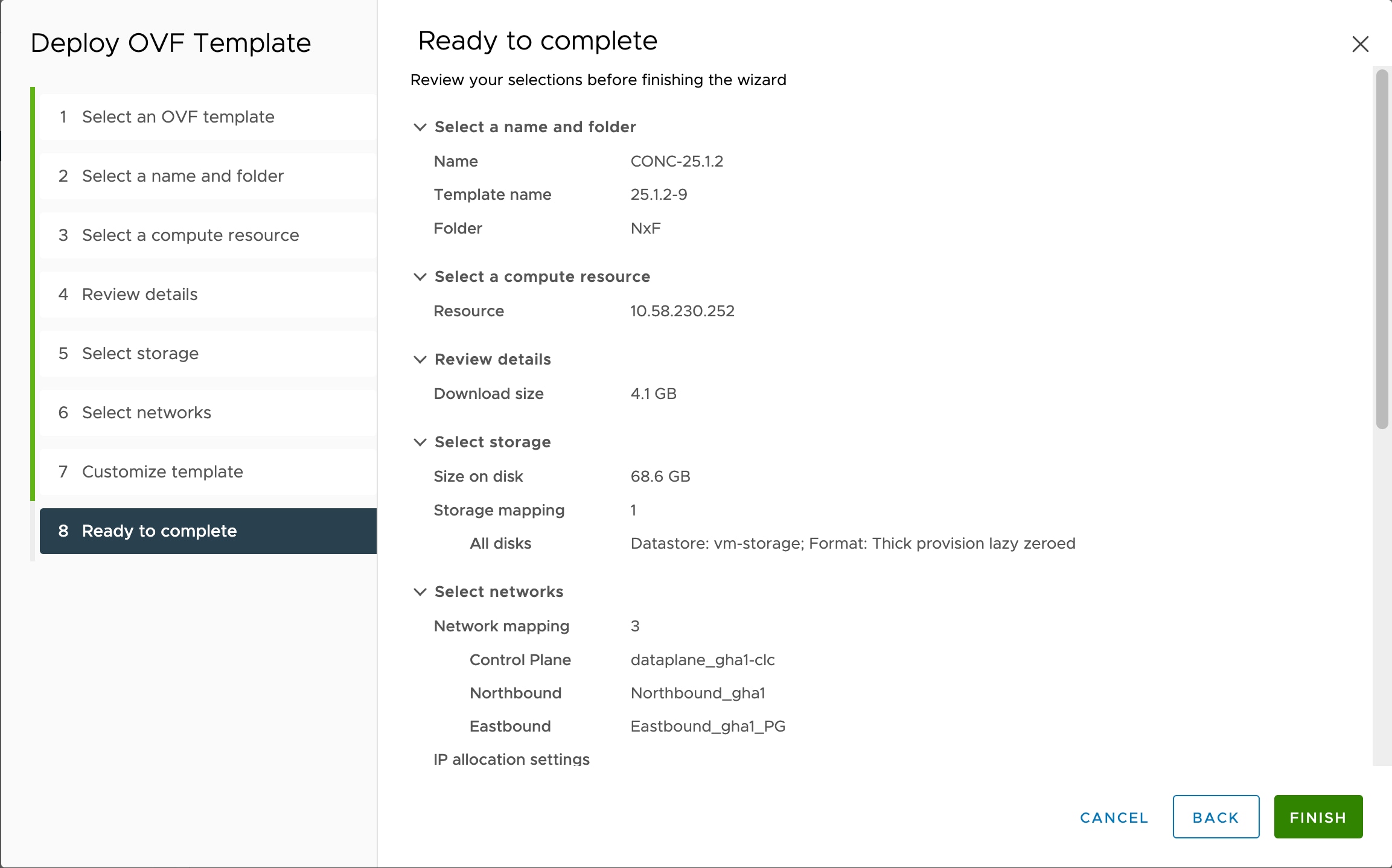
The OVA deployment is completed for the supercluster nodes.