Connect ONT to network

This chapter provides information for cabling the XGS-PON ONT.

Connect the ONT to Ethernet service

Connect the ONT to Ethernet service to begin data transmission.

Before you begin

Requirements

  • Ensure that all the safety instructions are followed before connecting the ONT to a network.

  • Ensure that you use a Ciena-recommended Ethernet LAN cable or an equivalent cable.

  • Ensure that the ONT must not be connected to a UPS device or DC power interface.

Procedure


Step 1

Locate the power over Ethernet cable.

Step 2

Connect the Ethernet LAN cable into the RJ-45 Ethernet port of the ONT. The following figure shows the Ethernet connection on the ONT.

Figure 1. Power over Ethernet cable - ENC-10G-ONT-14A XGS-PON ONT
Figure 2. Power over Ethernet cable - ENC-10G-ONT-01PR XGS-PON ONT

Connect the ONT to a network

Requirements

  • Ensure that all the safety instructions are followed before connecting the ONT to a network.

  • The optical strength of the ONT must be in the range of -8 dBm to -28 dBm for proper functioning.

Before you begin

Connect the XGS-PON ONT to a network before startup.

Procedure


Step 1

Remove the dust covers from the SC/APC optical connector.

Step 2

Clean the connector, if required.

Step 3

Plug in the fiber connector to the XGS-PON port.

Figure 3. Network connection

Connect the ONT to analog telephone

Requirements

  • Ensure that all the safety instructions are followed before connecting the ONT to the analog telephone.

  • Ensure that you use a Ciena-recommended RJ-11 cable or an equivalent cable.

  • Ensure that the ONT must not be connected to a UPS device or DC power interface.

Before you begin

Connect the XGS-PON ONT to the analog telephone.

Procedure


Step 1

Locate the analog telephone cable.

Step 2

Connect RJ-11 connector of the analog telephone cable into the FXS port of the ONT and the other end into the analog device.

The following figure shows the analog telephone connection on the ONT.

Figure 4. Analog telephone connection on the ONT

Step 3

Ensure that the FXS LED is green when the voice service is configured and VoIP is registered.


Connect the ONT to power by means of a UPS device

Requirements

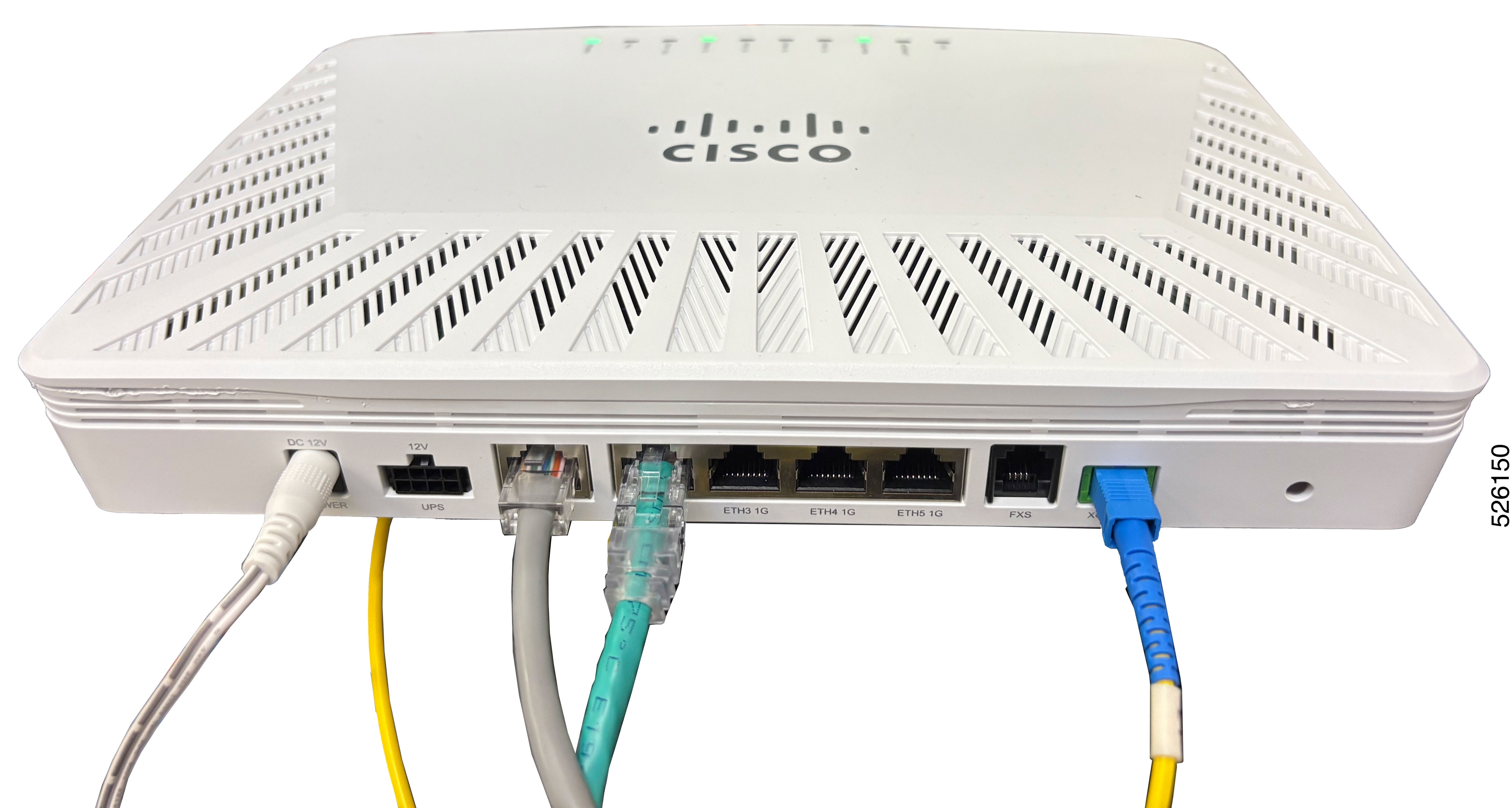
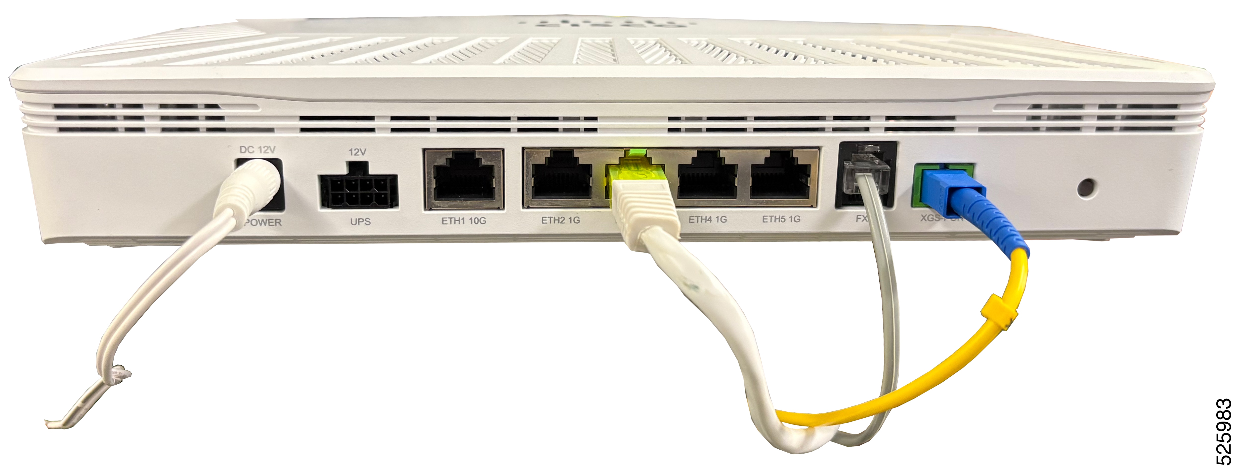
  • Ensure that the ONT is connected to a network.

  • Ensure that the output of the UPS is what the ONT requires.

  • Ensure that the ONT must not be connected to a DC power interface.

Overview

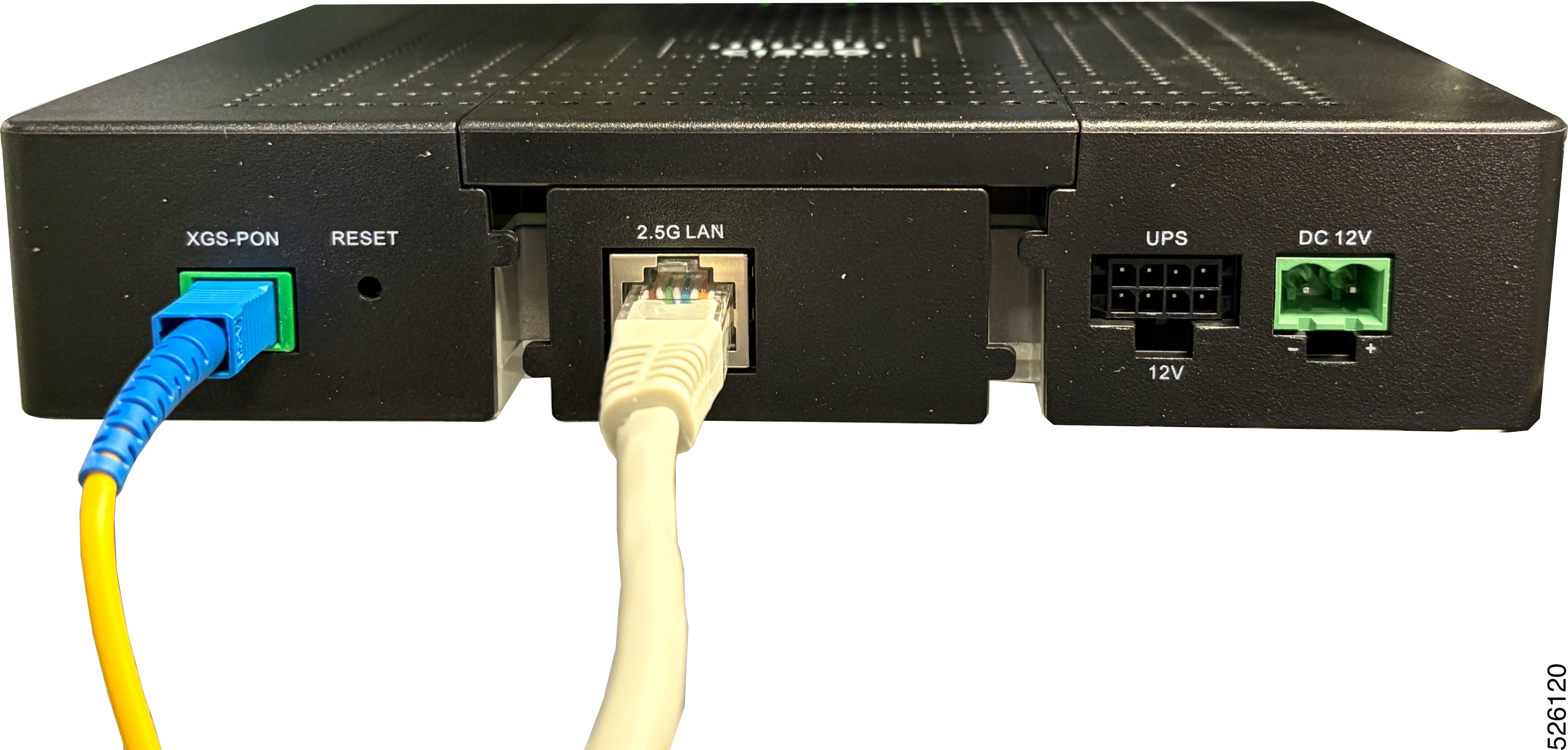
The ONT provides an option to connect battery backed power supply (for example, UPS) for uninterrupted operation. A 2x4 Molex connector is provided on the front panel of the unit for the same. We do not intend to supply UPS along with ONT so you need to procure it. Pin-out of the front panel UPS connector is given below. Follow the pin-out to prepare cable and connect UPS with ONT.

The following table lists the UPS pin-out.

Table 1. UPS pin-out

UPS pin-out

Definition

1

Not connected

2

Low battery

3

Replace battery

4

Battery in (ground)

5

Ground

6

Battery missing

7

On battery

8

Battery in (12V)

The UPS connects to the residence’s 110/220 V AC; 50/60 Hz power, converts the AC voltage to 12 VDC, and monitors the power source and battery for alarm conditions. The ONT is meant for indoor installation.

The ONT may be used with IEC/ UL certified BATTERY BACKUP (for UPS connector) with Output: 12 VDC, 30 W, complies with Limited Power Source, Tma = 40 degree C, and minimum operating altitude 2000 meters. Support of the UPS requires purchase of a 1m, 3m or 6m cord with 8-pin power connector interface ordered separately in addition to the UPS. There may also be additional UPS options available.

The ONT provides alarm monitoring for AC power failure, battery present, battery charge level, and battery end of life on its UPS connector. These alarms are transported over the PON to the service provider’s alarm network.

The indoor UPS is rated for indoor installations (up to 40°C/104°F). Units are configured with North American 3-prong Type B power plug. There are two versions available: grounded and floating. The grounded unit is designed to pass ground to the ONT for added protection against power surges and interference. The floating unit does not pass ground across the transformer and is used when service providers prefer to isolate the ground of the ONT from the house ground.

Before you begin

Connect the XGS-PON ONT to a UPS device to provide power to the ONT.

Procedure


Step 1

Plug the UPS connector into the UPS port of the ONT.

The following figure shows the UPS power connection on the ONT.

Step 2

Ensure that the POWER LED is orange.


Install the external power adapter

Requirements

  • All DC power cables must meet the requirements of local and national electrical codes.

  • Ensure correct prongs are installed on the power adapter, based on the country of installation.

Overview

  • Install the DC pin of the external adapter to the power port on the front of the ONT and the adapter to an AC supply socket.

  • All cables must run in accordance with cabling plans. Pay particular attention to the site requirements.

Before you begin

Install the external power adapter. A 3.3 feet (1 meter) external 12V, 24W, AC/ DC adapter is shipped with the ONT.

Procedure


Step 1

Locate the AC/DC power adapter that comes with the ONT. The following figure shows the AC/DC adapter shipped with ONT for NA installation.

Figure 5. AC/DC power adapter

Step 2

For ONT variant applicable for NA installations, go to step 5.

Step 3

For other ONT variant shipped with country specific power adapters, fix the prong on the adapter by placing the prong over the adapter and sliding it downwards. The following figure shows the AC/DC adapter with country specific prongs.

Step 4

To replace the prong for the power adapter, press the PUSH button on the adapter, remove the existing prong, place the required prong.The following figure shows the PUSH button on the adapter.

Step 5

Plug the AC power adapter to the live AC power socket.

Step 6

Plug the other end of the AC power adapter into the ONT.

Step 7

Ensure the POWER LED is steady green.