Switch Fabric
This chapter describes the Cisco CRS 4-slot line card chassis switch fabric and switch fabric card (SFC). The following sections are included:
Switch Fabric Overview
The switch fabric is the core of the Cisco CRS 4-slot line card chassis. The switch fabric is implemented through switch fabric cards installed in the chassis. The switch fabric uses a cell-switched, buffered three-stage Benes switch fabric architecture. The switch fabric receives user data from an MSC and performs the switching necessary to route the data to the appropriate egress MSC.
The switch fabric is divided into four planes (plane 0 to plane 3) that are used to evenly distribute traffic across the switch fabric. Each switch fabric plane is independent and is not synchronized with one another. Each cell traverses the switch fabric using a single switch fabric plane. (Cells are not bit-sliced across the switch fabric.)
There are two types of switch fabric cards used in the line card chassis: QQ123 (40G fabric) and QQ123-140G (140G fabric). Each fabric card implements all three stages of the switch fabric.
The following figure shows the basic path of IP data packets through the Cisco CRS 4-slot line card chassis switch fabric. Note that the figure shows all three stages of the switch fabric provided by the fabric cards in the line card chassis.
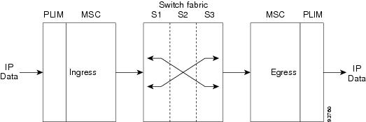
Ingress data packets are received at a physical interface on a PLIM and transferred to the associated MSC, where the packets are segmented into cells for efficient switching by the switch fabric hardware. Each MSC has multiple connections to each switch fabric plane, which it uses to distribute cells to each fabric plane. On egress, cells are reassembled into data packets before being transmitted by the egress MSC.
 Note | The cell structure used in the Cisco CRS 4-slot line card chassis switch fabric is a Cisco design and is not related to Asynchronous Transfer Mode (ATM) cells. |
Switch Fabric Operation
Several switch element components on each SFC perform the functions to implement each of the three stages (S1, S2, and S3) of the switch fabric. Each stage performs a different function:
- Stage 1 (S1)—Distributes traffic to Stage 2 of the fabric plane. Stage 1 elements receive cells from the ingress MSC and PLIM (or RP) and distribute the cells to Stage 2 (S2) of the fabric plane.
- Stage 2 (S2)—Performs switching and the first stage of the multicast function. Stage 2 elements receive cells from Stage 1 and route them toward the appropriate egress MSC and PLIM.
- Stage 3 (S3)—Performs switching, provides 2 times (2x) speedup of cells, and performs a second level of the multicast function. Stage 3 elements receive cells from Stage 2 and perform the switching necessary to route each cell to the appropriate egress MSC and PLIM.
Speedup Function
A line card chassis can contain up to 4 MSCs, each with 140 Gbps of bandwidth. To provide 140 Gbps of switching capacity for each MSC, the switch fabric must actually provide additional bandwidth to accommodate cell overhead, buffering, and congestion-avoidance mechanisms.
Congestion can occur in the switch fabric if multiple input data cells are being switched to the same destination egress MSC. Typically, little congestion exists between the S1 and S2 stages because there is little or no contention for individual links between the switch components. However, as multiple cells are switched from the S2 and S3 stages to the same egress MSC, cells might contend for the same output link.
To reduce the possibility of data cells being delayed during periods of congestion, the switch fabric uses 2 times (2x) speedup to reduce contention for S2 and S3 output links. The switch fabric achieves 2x speedup by providing two output links for every input link at the S2 and S3 stages.
S2 and S3 Buffering
Buffering is also used at the S2 and S3 stages of the switch fabric to alleviate any additional congestion that the switch fabric speedup does not accommodate. To ensure that this buffering does not cause cells to arrive out of sequence, the MSC resequences the cells before reassembling them into packets. To limit the amount of buffering required, a back-pressure mechanism is used for flow control (which slows the transmission of data cells to a congested destination). Back-pressure messages are carried in fabric cell headers.
Failure Operation
The routing system can withstand the loss of a single plane of the switch fabric with no impact on the system. The loss of multiple planes results in linear and graceful degradation of performance, but does not cause the routing system to fail.
Note | At least two planes of the switch fabric (an even plane and an odd plane) must be active at all times for the Cisco CRS 4-slot line card chassis to operate. Otherwise, the switch fabric fails, causing a system failure. |
Switch Fabric Cards
The Cisco CRS 4-slot line card chassis supports two types of switch fabric card. This section describes the cards and their indicators.
Switch Fabric Card Description
This section describes both the QQ123 and QQ123-140G switch fabric cards.
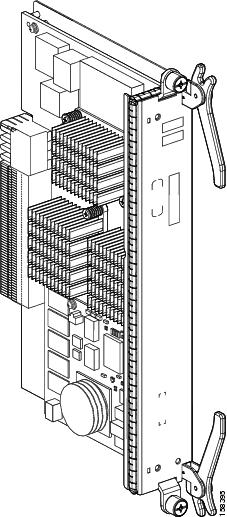
The switch fabric cards implement all three stages of the three-stage Benes switch fabric. Each card also implements one plane of the four-plane switch fabric. The following figure shows the QQ123 switch fabric card.
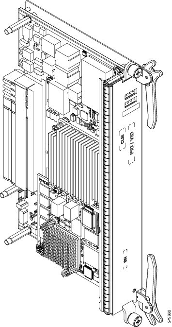
The following figure shows the QQ123-140G switch fabric card.
Switch Fabric Card Components
The switch fabric cards contain the following major components:
- S1 switch element—Implements Stage 1 of the switch fabric. Receives cells from the MSC (or RP) and distributes them to Stage 2.
- S2 switch element—Implements Stage 2 of the switch fabric. Receives cells from Stage 1, performs 2x speedup, and routes the cells toward the appropriate egress S3 element.
- S3 switch element—Implements Stage 3 of the switch fabric. Receives data cells from Stage 2 and performs switching of incoming cells to the appropriate egress links. The S2 and S3 switch elements are pure output-buffered switch elements with a central memory to buffer cells and queuing capabilities to distinguish between high-priority and low-priority traffic.
- Service processor—Controls the operation of the fabric card and provides the interface to the system control plane. The service processor performs card power up and power down, performs link-up and link-down processing, configures switch element components, updates the fabric group ID (FGID) for multicast traffic, and maintains cell configuration.
- Power modules—Take –48 VDC input power from the midplane and convert it to the voltages required by the components on the switch fabric card.
Note | Each stage of the three-stage Benes switch fabric is implemented with the same switch element components. However, during system startup, the components are programmed by Cisco IOS XR software to operate in S1, S2, or S3 mode, depending on their functions in the switch fabric. Each switch fabric card contains two S1, two S2, and four S3 components. |
Switch Fabric Card Physical Characteristics
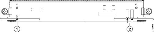
The following figure shows the front panel of the QQ123 switch fabric card. The front panel of the QQ123-140G card is similar.
|
1 |
Status LED |
2 |
Alphanumeric LEDs |
The front panel of the switch fabric cards contains:
- Status LED—Indicates the status of
the fabric card.
- Green—Indicates that the SFC is operating normally.
- Yellow—Indicates that a fault condition exists.
- Alphanumeric display—Displays switch fabric card messages.
The physical characteristics of both the QQ123 and QQ123-140G switch fabric cards are:
- Height—2 in. (5.0 cm)
- Depth—7.1 in. (18.0 cm)
- Width— 12.1 in. (30.7 cm)
- Weight—6 lb (2.7 kg)
- Power consumption—up to 130 W
 Feedback