Cisco CRS Carrier Routing System 4-Slot Line Card Chassis System Description
Bias-Free Language
The documentation set for this product strives to use bias-free language. For the purposes of this documentation set, bias-free is defined as language that does not imply discrimination based on age, disability, gender, racial identity, ethnic identity, sexual orientation, socioeconomic status, and intersectionality. Exceptions may be present in the documentation due to language that is hardcoded in the user interfaces of the product software, language used based on RFP documentation, or language that is used by a referenced third-party product. Learn more about how Cisco is using Inclusive Language.
- Updated:
- February 12, 2017
Chapter: Chassis Power System
Chassis Power
System
This chapter describes the Cisco CRS Carrier Routing System 4-Slot Line Card Chassis power system. The following sections are included:
Power specifications are provided in Cisco CRS 4-Slot Line Card Chassis System Specifications.
Power System Overview
The Cisco CRS Carrier Routing System 4-Slot Line Card Chassis can be configured with either an AC-input power subsystem or a DC-input power subsystem. Site power requirements differ depending on the source voltage used. Follow these precautions and recommendations when planning power connections to the router.
The Cisco CRS 4-slot line card chassis requires that at least the power shelves and their components be installed to operate properly. Two types of power shelves exist: an AC shelf and a DC shelf. An AC power shelf houses AC rectifiers, while a DC power shelf houses the DC power input module (PIM) and DC power input shelf. We recommend that you use only one type of power shelf in a chassis at a time.
The AC power system is redundant and contains the following components:
- One AC power shelf
- Four AC rectifiers within the AC power shelf
- Dual rectifier output buses, which provide redundant power inputs to chassis components
- Special components, such as DC-to-DC converters, OR-ing diodes, and EMI filters
The DC power system consists of the following components:
- DC power input shelf (Cisco product number: CRS-4-DC-INPUT)
- Power input module (PIM) (Cisco product number: CRS-4-DC-PIM)
- DC power supplies (Cisco product number: CRS-4-DC-SUPPLY)
AC Power Architecture
The AC power system uses a single power shelf to provide reliable, 1:1 redundant power to all chassis components. AC power enters the rectifiers via the power shelf and is converted to DC. DC outputs from the supplies form 2 separate distribution buses. Both buses distribute power through the midplane.
- AC rectifiers A0 and A1 supply –54 VDC to the A bus.
- AC rectifiers B0 and B1 supply –54 VDC to the B bus.
Because chassis components are powered by both A and B busses, the line card chassis can continue to operate normally if any two AC rectifiers fail or are not present. Only two operational rectifiers are required to operate the system if a fault prevents all four rectifiers from operating normally.
Individual chassis components have power-related devices (OR-ing diodes, inrush control circuits, and EMI filters) that are part of the chassis power architecture. These power-related devices form part of the dual power source (A and B bus) architecture, and enable online insertion and removal (OIR) of individual power modules.
AC Power System
The AC power system provides 4000 watts to power the line card chassis. The AC power system, which provides 1:1 power redundancy, contains the following components:
- One AC power shelf: Holds four AC rectifier modules.
- Four 2000 watt AC rectifier modules: Contains the AC input power connectors. These rectifiers convert 200- to 240-VAC input power to –54 VDC used by the line card chassis. Each AC rectifier is a field replaceable unit (FRU).
 Note | The power cables for the power shelves do not come pre-attached. |
AC Power Shelf
The AC power shelf is the enclosure that houses four AC rectifier modules and power distribution connections and wiring. The AC power shelf, shown below, is installed in the line card chassis from the front and plugs into the chassis power interface connector panel.
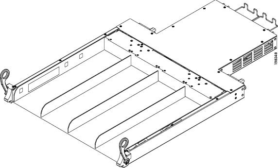
The AC power shelf physical dimensions are:
- Height—1.7 in. (4.3 cm)
- Width—16.8 in. (42.6 cm)
- Depth—16.2 in. (41.2 cm)
- Weight—25 lb. (11.3 kg) with all AC rectifiers installed
Input AC power enters into each of the four AC rectifiers in the shelf. The AC rectifiers convert AC power into DC power, provide filtering, and then pass the DC power to either the A or B bus in the chassis midplane.
To provide 1:1 redundancy, two AC rectifiers powers the A bus and the other two AC rectifiers powers the B bus. Each AC rectifier also has a service processor module that monitors the condition of each AC rectifier and provides status signals that indicate the health of the power supplies (see the AC Rectifier Indicators section).
AC Rectifier
The AC rectifier is an AC power supply that converts input AC power into the DC power necessary to power chassis components. The rectifier takes input AC power, rectifies the AC into DC, provides filtering and control circuitry, provides status signaling, and passes the DC power to either the A or B bus in the chassis midplane. Each AC rectifier has two self-contained cooling fans that draws air through the module.
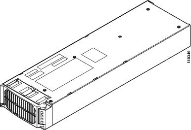
The AC rectifier module physical dimensions are:
AC power enters the AC rectifier at the rear of the power shelf. When the power enters the AC rectifier, internal circuits rectify the AC into DC, filter, and regulate it. The DC-to-DC process converts the 350- VDC primary side power to –54-VDC isolated secondary power.
A service processor (SP) module in each AC rectifier monitors the status of each AC rectifier. The service processor communicates with the system controller on the route processor (RP). The service processor circuitry monitors the AC rectifier fault and alarm conditions.
Each AC rectifier contains an ID EEPROM that stores information used by control software (for example, part number, serial number, assembly deviation, special configurations, test history, and field traceability data).
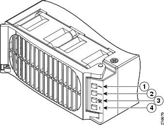
AC Rectifier Indicators
Each AC rectifier has power and status indicators. The AC rectifier shares auxiliary power with one another; therefore, the indicators are operational even when the AC rectifier is not powered from its input voltage. The indicators are shown in this figure.
|
1 |
AC OK |
3 |
Service |
|
2 |
DC OK |
4 |
Fault |
The following table lists the AC rectifier status indicators and their functions.
|
Name |
Color |
Function |
|---|---|---|
|
AC OK |
Green |
Input voltage is within operating range. |
|
DC OK |
Green |
Output voltage is within range. |
|
Service |
Amber |
Indicates a thermal condition in conjunction with other LEDs. |
|
Fault |
Red |
The AC rectifier is not operating normally. |
The following table lists the LED readings during failure conditions.
|
Condition |
AC OK LED |
DC OK LED |
Service LED |
Fault LED |
|---|---|---|---|---|
|
OK |
On |
On |
Off |
Off |
|
Thermal Alarm (5C before shutdown) |
On |
On |
On |
Off |
|
Thermal Shutdown |
On |
Off |
On |
On |
|
Defective Fan |
On |
Off |
Off |
On |
|
Blown AC Fuse in Unit |
On |
Off |
Off |
On |
|
No AC >15ms (single unit) |
Off |
On |
Off |
Off |
|
AC present but not within limits |
On (blinking) |
Off |
Off |
Off |
|
AC not present |
Off |
Off |
Off |
Off |
|
Boost Stage Failure |
On |
Off |
Off |
On |
|
Over Voltage Latched Shutdown |
On |
Off |
Off |
On |
|
Over Current |
On |
On (blinking) |
Off |
Off |
|
Noncatastrophic Internal Failure |
On |
On |
Off |
On |
|
Standby (remote) |
On |
Off |
Off |
Off |
|
Service Request (PMBus mode) |
On |
On |
On (blinking) |
Off |
DC Power System
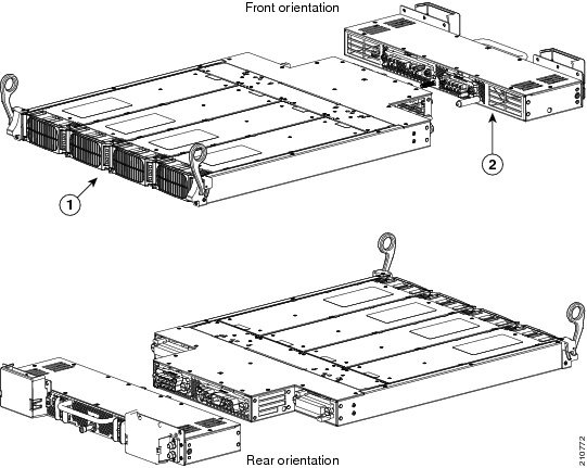
This section provides an overview of the DC power system on the Cisco CRS 4-slot line card chassis. For a complete description of DC power on this routing system, see the Cisco CRS Carrier Routing System 4-Slot Line Card Chassis Installation Guide . The DC power shelf consists of two major components, as shown in the following figure:
The figure shows the power supplies installed in the DC power input shelf.
|
1 |
DC power input shelf |
2 |
Power input module (PIM) |
When installing the DC power shelf, these two components are mated to create the complete DC power shelf.
The Cisco CRS 4-slot line card chassis DC power system provides 4,000 watts to power the chassis. (To provide power redundancy, up to 8,000 watts are available.) Each DC-powered chassis contains four DC power supplies for 2N redundancy. The power input module (PIM) provides the input power connections. Note that each power connection has two cables: –48 VDC and return. The power input module (PIM), DC power input shelf, and the power supplies are field replaceable.
The Cisco CRS 4-slot line card chassis requires a total of four dedicated pairs of 60-A DC input power connections, one pair for each of the power supplies, to provide redundant DC power to the Cisco CRS 4-slot line card chassis midplane.
For full 2N redundancy, we recommend that you have two independent –48 VDC power sources to provide power to the Cisco CRS 4-slot line card chassis. Connect the two 60-A DC inputs on the left to one wiring block, and the two 60-A DC inputs on the right to the other wiring block.
DC Power Shelf Guidelines
At sites where the Cisco CRS 4-slot line card chassis is equipped with a DC power input shelf and power supplies, observe the following guidelines:
- All power connection wiring should follow the rules and regulations in the National Electrical Code (NEC) and any local codes.
- Each DC-input power entry module connection is rated at 60-A maximum. A dedicated, commensurately rated DC power source is required for each power supply connection.
- Each power supply requires one –48 VDC input, or four inputs for each power shelf (in which each input consists of a pair of positive and negative wires), and one power-shelf grounding wire.
- For DC power cables, we recommend that you use commensurately rated, high-strand-count copper wire cable. Each DC power supply requires one 48 VDC input, which means that there are two wires for each power supply, or eight total wires (four pairs) for each power shelf, plus the grounding wire. The length of the wires depends on the router’s location. These wires are not available from Cisco Systems; they are available from any commercial vendor.
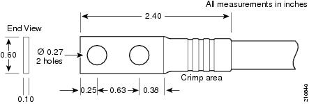
- DC power cables must be terminated by cable lugs at the power-shelf end. The lugs should be dual hole and able to fit over M6 terminal studs at 0.625-in (15.88-mm) centers (for example, Panduit part number LCD2-14A-Q or equivalent).
Color Coding of the Source DC Power Cable
The color coding of the source DC power cable leads depends on the color coding of the site DC power source. Typically, green or green and yellow indicates that the cable is a ground cable. Because no color code standard exists for the source DC wiring, you must ensure that the power cables are connected to the DC-input power shelf terminal studs in the proper positive (+) polarity and negative (–) polarity.
DC Cable Polarity Labels
Sometimes, the source DC cable leads might have a positive (+) or a negative (–) label. This label is a relatively safe indication of the polarity, but you must verify the polarity by measuring the voltage between the DC cable leads. When making the measurement, the positive (+) lead and the negative (–) lead must always match the (+) and (–) labels on the power shelf.
 Caution | The DC-input power supplies contain circuitry to prevent damage due to reverse polarity, but you should correct a reverse-polarity condition immediately. |
|
Nominal input voltage |
Supports –48 VDC and –60 VDC systems(range: –40 to –72 VDC)
|
||
|
Input line current |
50-A maximum at –48 VDC40-A maximum at –60 VDC |
||
|
Inrush current |
60-A peak at –75 VDC(maximum for 1 ms) |
Note | When wiring the DC power shelf, be sure to attach the ground wire first. When removing the wiring, be sure to remove the ground wire last. The ground wire must be attached with a torque value of 30 in-lb. The power cables should also be attached with a torque value of 30 in-lb. |
Wiring Block on the PIM
Each wiring block on the power input module (PIM) contains four sets of terminals, two positive and two negative. Each wiring block is covered by a plastic block cover that snaps onto the wiring block and is secured by a screw to a torque value of 50 in.-lb.
You must remove the block cover before you work with the wires.
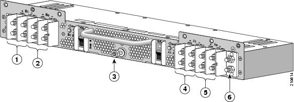
|
1 |
Power supply B1 wiring block |
4 |
Power supply A1 wiring block |
|
2 |
Power supply B0 wiring block |
5 |
Power supply A0 wiring block |
|
3 |
Coupling screw |
6 |
Ground lug nuts |
Input-Power-Present LEDs
The DC power Input-Power-Present LEDs provide a visual indication to service personnel that there is voltage present across the input terminal’s connection. The LED provides a warning to the service person that there is power present.
Note | Power should be disconnected before servicing the input power connections. Always check for hazardous voltage with a multimeter device before servicing the unit. |
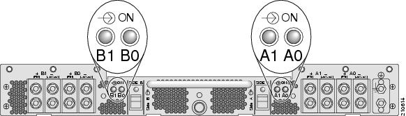
The input-power-present LED starts to light up when the input voltage reaches 20 VDC; the LED gets brighter as voltage increases. The input-power-present LED is fully lit when the input voltage reaches 38 VDC.
Note | If an input-power-present LED is not lit, check for 1) the presence of voltage, and 2) the polarity of the corresponding wiring block. |
DC Power Wire Characteristics
For signal degradation to be averted, a conductor must be large enough to prevent its impedance from creating a voltage drop equal to 2 percent of the reference voltage. Also, the protective earth conductor must be large enough to carry all the current if the –48 VDC return fails. This latter requirement is for safety. Full fault redundancy is achieved by having conductors of equal size for the protective earth ground and the –48 VDC return of the switch.
For site preparation, proper wire size and insulation must be selected. For a planned power distribution, calculation must be done prior to distribution to meet the proper voltage drop and temperature rise.
For wire gauges that prevent unacceptable voltage drops over different lengths of copper wire, see the following table. For the resistance of 1000 feet of copper wire for each gauge of wire. see "Resistance for Each Gauge of Copper" table. These references are for planning purposes and might be further subject to local laws and practices.
The following table provides the gauges of wire needed for wire lengths and DC power currents.
Note | We recommend using at least 50-A of DC current and 6-gauge wire. |
|
DC Current (Amps) |
25 Feet |
50 Feet |
75 Feet |
100 Feet |
150 Feet |
200 Feet |
400 Feet |
|---|---|---|---|---|---|---|---|
|
5-A |
18 gauge |
14 gauge |
14 gauge |
12 gauge |
10 gauge |
8 gauge |
6 gauge |
|
10-A |
14 gauge |
12 gauge |
10 gauge |
8 gauge |
8 gauge |
6 gauge |
2 gauge |
|
15-A |
14 gauge |
10 gauge |
8 gauge |
8 gauge |
6 gauge |
4 gauge |
2 gauge |
|
20-A |
12 gauge |
8 gauge |
8 gauge |
6 gauge |
4 gauge |
2 gauge |
0 gauge |
|
25-A |
12 gauge |
8 gauge |
6 gauge |
4 gauge |
4 gauge |
2 gauge |
0 gauge |
|
30-A |
10 gauge |
8 gauge |
6 gauge |
4 gauge |
2 gauge |
2 gauge |
00 gauge |
|
35-A |
10 gauge |
6 gauge |
4 gauge |
2 gauge |
2 gauge |
1 gauge |
000 gauge |
|
40-A |
8 gauge |
6 gauge |
2 gauge |
2 gauge |
2 gauge |
0 gauge |
000 gauge |
|
45-A |
8 gauge |
6 gauge |
4 gauge |
2 gauge |
1 gauge |
0 gauge |
0000 gauge |
|
50-A |
8 gauge |
4 gauge |
4 gauge |
2 gauge |
1 gauge |
00 gauge |
N/A |
|
55-A |
8 gauge |
4 gauge |
2 gauge |
2 gauge |
0 gauge |
00 gauge |
N/A |
|
60-A |
8 gauge |
4 gauge |
2 gauge |
2 gauge |
0 gauge |
00 gauge |
N/A |
|
65-A |
6 gauge |
4 gauge |
2 gauge |
1 gauge |
0 gauge |
000 gauge |
N/A |
|
70-A |
6 gauge |
4 gauge |
2 gauge |
1 gauge |
00 gauge |
000 gauge |
N/A |
|
75-A |
6 gauge |
4 gauge |
2 gauge |
1 gauge |
00 gauge |
000 gauge |
N/A |
|
100-A |
4 gauge |
2 gauge |
1 gauge |
00 gauge |
000 gauge |
N/A |
N/A |
The following table provides the correlation between wire gauge and the resistance (in Ohms for each 1000 feet of wire) for copper wire.
|
Wire Gauge |
Ohms for each 1000 Feet of Wire |
|---|---|
|
0000 |
0.0489 |
|
000 |
0.0617 |
|
00 |
0.0778 |
|
0 |
0.098 |
|
1 |
0.1237 |
|
2 |
0.156 |
|
3 |
0.1967 |
|
4 |
0.248 |
|
5 |
0.3128 |
|
6 |
0.3944 |
|
7 |
0.4971 |
|
8 |
0.6268 |
|
9 |
0.7908 |
|
10 |
0.9968 |
|
11 |
1.257 |
|
12 |
1.5849 |
|
13 |
1.9987 |
|
14 |
2.5206 |
|
15 |
3.1778 |
|
16 |
4.0075 |
|
17 |
5.0526 |
|
18 |
6.3728 |
|
19 |
8.0351 |
|
20 |
10.1327 |
|
21 |
12.7782 |
|
22 |
16.1059 |
 Feedback