Route Processor
This chapter describes the route processor (RP) card. The following sections are included:
- Route Processor Overview
- Primary and Standby Arbitration
- RP Card to Fabric Module Queuing
- Performance Route Processor
Route Processor Overview
The route processor (RP) card is the system controller for the Cisco CRS 4-slot line card chassis. It performs route processing and distributes forwarding tables to the MSCs. Although the routing system contains two RP cards, only one RP is active at a time. The other RP operates in standby mode, ready to assume control if the primary RP fails.
The RP card provides route processing, alarm, fan, and power supply controller function in the Cisco CRS 4-slot line card chassis. The RP card controls fans, alarms, and power supplies through the use of an i2c communication link from the RP card to each fan tray/power supply.
Two RP cards are required per chassis for redundancy—one is primary , and the other is standby. An RP card can be inserted in either of the two dedicated slots in the chassis.
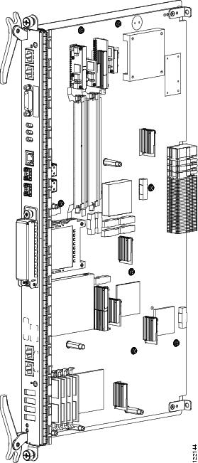
This figure illustrates the route processor card.
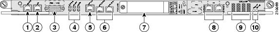
Details on the faceplate of the RP card are shown in this figure and are described in the succeeding table.
|
1 |
Console port |
6 |
Control Ethernet ports |
|
2 |
AUX port |
7 |
PC card slot |
|
3 |
Alarm port |
8 |
EXT CLK ports |
|
4 |
Error LED array |
9 |
Alphanumeric LEDs |
|
5 |
Management Ethernet port |
10 |
Status LEDs |
|
RP Card Component |
Description |
|---|---|
|
Hard drive |
An IDE hard drive is used to gather debugging information, such as core dumps from the RP or MSCs. It is typically powered down and activated only when there is a need to store data. |
|
Memory |
Memory resides in a SIMM module on the RP card. The RP can be configured with 2 or 4 GB of memory. |
|
PCMCIA Subsystems |
Two PCMCIA flash slots provide support for 1 Gb of flash subsystem storage, each. One of the PCMCIA flash subsystems is accessible externally and is removable, and allows you to transfer images and configurations by plugging in a PCMCIA flash card. The other PCMCIA flash subsystem is fixed to the RP, for permanent storage of configurations and images. |
|
CPU |
A single MPC7457 (1.2-Ghz) Power-PC module performs route processing. The CPU also serves as the MSC service processor (SP), and monitors the RP temperature, voltages, power supply margining (during factory test), and ID EEPROM. |
|
RJ45 Ethernet port |
An RJ-45 10/100/1000 copper Ethernet port is available for providing connectivity to network management systems. |
|
Fast Ethernet Midplane Connector |
Internal 100 Mbps Fast Ethernet (FE) midplane connections connect each MSC in the chassis to both RP cards. These FE connections are traces in the midplane. There are also FE connections to the power supplies of the fans. These connections all form part of the control plane. |
Primary and Standby Arbitration
The two RP cards in a Cisco CRS 4-slot line card chassis operate in a primary-standby relationship. The routing system performs the following tasks to determine which RP is primary and which is standby:
- At chassis power-up, each RP boots its board components and runs self-tests.
- The RP cards exchange messages with each other and with the service processors (SPs) on all other boards. Each RP examines its outgoing “Reset” lines to verify that they are inactive.
- Based on the results of its self-test, each RP decides whether it is ready to become primary (active). If so, the RP asserts the “Ready” signal to its on-board arbitration unit, which propagates the “Ready” signal to the other RP.
- The arbitration hardware chooses the primary RP and asserts a “Primary” signal to the chosen RP, along with an interrupt. The arbitration hardware chooses the primary RP from the RP cards that have asserted “Ready.” The hardware also propagates the “Primary” signal to the other RP, along with an interrupt.
- Software on each RP reads its “Primary” signal, and branches accordingly to “Primary” or “Standby” code.
- If the primary RP is removed, powered down, or voluntarily de-asserts its “Ready” signal, the standby RP immediately receives an asserted “Active” signal, along with an interrupt.
RP Card to Fabric Module Queuing
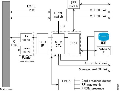
As shown in the following figure, the RP mates with the Cisco CRS 4-slot line card chassis midplane. The RP connects to the switch fabric through two fabric interface modules (From fabric and To fabric) that are similar to the fabric interface of the MSC (see the MSC To Fabric Section and Queuing).
- The “From fabric” module (on the RP receive path) queues the data from the switch fabric and reorders and reassembles the cells into packets before queuing them for slow-path processing.
- The “To fabric” module (on the RP transmit path) queues the packets and segments them into cells before transmitting them to the switch fabric.
Performance Route Processor
The Performance Route Processor (PRP) is also available for the Cisco CRS 4-slot line card chassis. The PRP provides enhanced performance for both route processing and system controller functionality.
Two PRP cards are required per chassis for a redundant system. The PRP can be inserted in either of the two dedicated RP slots in the Cisco CRS 4-slot line card chassis. When two PRPs are installed, one PRP is the "Active" RP and the other is the “Standby” RP.
 Note | A chassis may not be populated with a mix of RP and PRP cards. Both route processor cards should be of the same type (RP or PRP). |
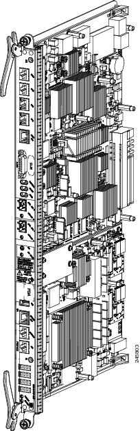
This figure shows the PRP card.
The PRP has the following physical characteristics:
Performance Route Processor Front Panel
The PRP front panel includes:
- Two 1GE (SFP) or 10G (SFP+) ports for 1-GE or 10-GE uplinks
- Service Ethernet RJ45 port
- Console port
- Auxiliary port
- Push button switch to Initiate OIR process
- LED to indicate OIR status and readiness for extraction
- Alphanumeric Display
- LEDs for card status and RP Active or Standby status
- USB socket
This figure shows the front panel of the PRP card.
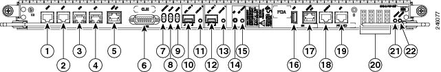
|
1 |
BITS 0 |
12 |
Control Ethernet 1 port (SFP or SFP+) |
|---|---|---|---|
|
2 |
BITS 1 |
13 |
Link/Active 1 LED |
|
3 |
DTI 0 |
14 |
OIR push button—Press to initiate OIR process |
|
4 |
DTI 1 |
15 |
OIR Ready LED |
|
5 |
Management Ethernet RJ45 port |
16 |
USB socket |
|
6 |
Alarm connector |
17 |
Service Ethernet RJ45 port |
|
7 |
Critical Alarm LED |
18 |
Console port |
|
8 |
Major Alarm LED |
19 |
Auxiliary port |
|
9 |
Minor Alarm LED |
20 |
Alphanumeric LED Display |
|
10 |
Control Ethernet 0 port (SFP or SFP+) |
21 |
PRIMARY LED—PRP active or standby indicator |
|
11 |
Link/Active 0 LED |
22 |
STATUS LED—Card status indicator |
Performance Route Processor Overview
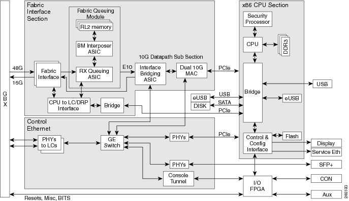
The CRS PRP for the Cisco CRS 4-slot line card chassis is a next generation Intel-based RP that increases the CPU compute power, memory and storage capacity. The PRP provides both route processing and system controller functionality for enhanced performance.
A CPU interface and system control ASIC provides resources and communication paths between the CPU and the rest of the system to provide line card management, configuration, monitoring, protocol control, and exception packet handling. The fabric queuing portion of this ASIC acts as the fabric interface to handle the traffic to the fabric. Traffic from the fabric is handled by the ingress queuing portion of an interface bridging FPGA.
This figure shows a block diagram of the PRP card.
- Performance Route Processor Memory Options
- Initiate OIR Pushbutton
- Control and Management Ports
- Console and Aux Ports
- Service Ethernet Port
- USB Port
- Alarm Port
Performance Route Processor Memory Options
The following memory configurations are supported by the CPU memory controller:
- Three 2GB DDR3 DIMMs, for a total of 6GB (Cisco product ID: CRS-8-PRP-6G)
- Three 4GB DDR3 DIMMs, for a total of 12GB (Cisco product ID: CRS-8-PRP-12G)
Note | The memory on the 6GB PRP is not upgradable to 12GB. |
Initiate OIR Pushbutton
The PRP front panel includes an OIR pushbutton (see figure Figure 1). Pressing the OIR button initiates the OIR process and avoids the loss of card information caused by a surprise extraction.
If a card is extracted without initiating the OIR process (surprise extraction), the saving of logs or other important information is not possible. Although surprise extraction is supported, using the OIR process allows you to save important card information and logs.
After pressing the button, the OIR Ready LED (see figure Figure 1) blinks during the OIR process. When the OIR process is complete, the OIR Ready LED glows solidly to indicate that the board is ready for extraction.
If for some reason the OIR process cannot be completed, the OIR Ready LED will continue blinking. If this occurs, you should check the log and console messages for a failure reason.
If the card is not removed within five minutes, the PRP resets itself and the OIR Ready LED will stop glowing.
The OIR process operates as described even if the PRP is not in a redundant configuration or if the standby PRP is not ready.
Control and Management Ports
Two Control Ethernet optical ports (CNTL ETH 0, CNTL ETH 1) provide connectivity to network control systems. These ports use small form-factor pluggable (SFP or SFP+) modules to provide external Gigabit Ethernet (GE) or 10-Gigabit Ethernet (10-GE) connections.
A Management RJ45 port (MGMT ETH) provides connectivity to network management systems.
Console and Aux Ports
This table lists the pinouts for the Console (CON) and Auxiliary (AUX) RJ45 ports on the PRP (see figure Figure 1).
|
Pin |
Console Port |
Aux Port |
|---|---|---|
|
1 |
Request to send (RTS) |
Request to send (RTS) |
|
2 |
Data terminal ready (DTR) |
Data terminal ready (DTR) |
|
3 |
Transmit data (TxD) |
Transmit data (TxD) |
|
4 |
EMI Filter Ground (Gnd Console) |
EMI Filter Ground (Gnd Aux) |
|
5 |
EMI Filter Ground (Gnd Console) |
EMI Filter Ground (Gnd Aux) |
|
6 |
Receive data (RxD) |
Receive data (RxD) |
|
7 |
Carrier detect (CD) |
Carrier detect (CD) |
|
8 |
Clear to send (CTS) |
Clear to send (CTS) |
Service Ethernet Port
PRP functions include a Service Ethernet feature that enhances serviceability and troubleshooting of the system. The Service Ethernet RJ45 port provides a backdoor mechanism into the PRP if the main CPU subsystem is stuck and cannot be recovered.
Through the Service Ethernet connection, you can perform the follow functions:
- Reset any cards in the chassis, including the local PRP
- Perform console attachment to other CPUs to support console tunneling in the chassis
- Dump memory or device registers on the PRP
USB Port
The PRP has an external USB port on the faceplate for connecting a USB 2.0 thumb flash drive. The external devices connected to this port can be used for logging, external file transfer, and installing software packages.
Alarm Port
This table lists the pin outs for the Alarm port on the PRP (see figure Figure 1).
|
Signal Name |
Pin |
Description |
|---|---|---|
|
Alarm_Relay_NO |
1 |
Alarm relay normally open contact |
|
Alarm_Relay_COM |
2 |
Alarm relay common contact |
|
Alarm_Relay_NC |
9 |
Alarm relay normally closed contact |
Only Pins 1, 2, and 9 are available for customer use. The remaining pins are for Cisco manufacturing test, and should not be connected. Use a shielded cable for connection to this port for EMC protection.
 Feedback