IS-IS Configuration Guide for Cisco 8000 Series Routers, Cisco IOS XR Releases

PDF

IS-IS Configuration Guide for Cisco 8000 Series Routers, Cisco IOS XR Releases

IS-IS penalties for link loss anomalies

Want to summarize with AI?

Log in

Explains iS-IS penalty for link loss anomaly and the technical context you need before you configure or verify IS-IS behavior.


Summary

IS-IS penalty for link loss anomaly enables Cisco IOS XR software to dynamically adjust routing metrics whenever synthetic packet loss measurements indicate anomalies on particular network interfaces. This process ensures traffic is rerouted automatically to maintain optimal network reliability.

The key components involved in the process are:

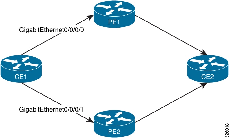
  • Customer edge devices (CE1 and CE2): Serve as the source and destination routers in the network topology.

  • Provider edge routers (PE1 and PE2): Connect CE devices and provide alternate routing paths (Path 1 and Path 2).

  • Cisco IOS XR software metric fallback anomaly loss command: Configured on interface(s) to modify metrics based on detected anomalies.

  • Synthetic Loss Measurement: Continuously monitors packet loss and triggers anomaly detection as needed.

Workflow

Figure 1. Traffic flow under metric fallback anomaly loss

The process involves these stages:

  1. Detection of anomaly: When the measured packet loss on Path 1 exceeds a pre-defined upper-bound threshold, the Cisco IOS XR software flags a loss anomaly.
  2. Notification: Cisco IOS XR communicates the loss anomaly to the IS-IS routing process.
  3. Metric adjustment: The metric fallback anomaly loss command on the affected interface instructs IS-IS to modify the interface metric.
  4. Traffic rerouting: IS-IS recalculates its shortest path, and Cisco IOS XR reroutes traffic from Path 1 to Path 2.
  5. Anomaly recovery: When packet loss recedes below the lower-bound threshold:
    • The synthetic loss measurement system clears the anomaly
    • IS-IS reverts the interface metric to its original value
    • Cisco IOS XR software reroutes traffic back to Path 1

Procedure

1.

Enter the IS-IS interface configuration mode, and configure point-to-point service under the IS-IS interface.

Example:

Router# configure terminal
Router(config)# router isis 1
Router(config-isis)# interface GigabitEthernet0/2/0/1
Router(config-isis-if)# point-to-point
2.

Configure the metric fallback anomaly loss increment for both IPv4 and IPv6 address families.

Example:

Router(config-isis-if)# address-family ipv4 unicast
Router(config-isis-if-af)# metric fallback anomaly loss increment 500
Router(config-isis-if-af)# exit
Router(config-isis-if)# address-family ipv6 unicast
Router(config-isis-if-af)# metric fallback anomaly loss increment 500
Router(config-isis-if-af)# exit
Router(config-isis-if)# exit
Router(config-isis)# commit
                            
3.

Use the show isis database verbose command to verify the metric fallback anomaly loss increment configuration.

Example:

Router# show isis database verbose r100
Fri Oct 11 10:49:17.836 PDT
IS-IS 1 (Level-2) Link State Database
LSPID LSP Seq Num LSP Checksum LSP Holdtime/Rcvd ATT/P/OL
r100.00-00 * 0x0000000b 0xc725 1188 /* 0/0/0 Metric: 10 IS-Extended r101.00 Local Interface ID: 10, Remote Interface ID: 7 Interface IP Address: 10.1.1.100 Neighbor IP Address: 10.1.1.101 Physical BW: 1000000 kbits/sec, 125000000 bytes/sec Link Average Delay: 704 us Link Min/Max Delay: 483/871 us Link Delay Variation: 127 us Metric: 10         MT (IPv6 Unicast) IS-Extended r101.00 Local Interface ID: 10, Remote Interface ID: 7 Interface IPv6 Address: 2001:1000::100 Neighbor IPv6 Address: 2001:1000::101 Physical BW: 1000000 kbits/sec, 125000000 bytes/sec Link Average Delay: 704 us Link Min/Max Delay: 483/871 us Link Delay Variation: 127 us Total Level-2 LSP count: 1 Local Level-2 LSP count: 1