Replace Chassis Components


Note


The images in this chapter are only for representation purposes, unless specified otherwise. The chassis' actual appearance and size may vary.

Caution


Whenever you replace any card, you must always ensure to secure the ejector thumbscrews properly.

Replace Chassis Door Foam Air Filters


Note


In general, we recommend that you inspect the air filter every 3 months and replace. Air filters are consumable items and must be ordered separately by customers. Customers may contact TAC for assistance in identifying the correct air filter PID to order. We recommend having spare air filters in stock.

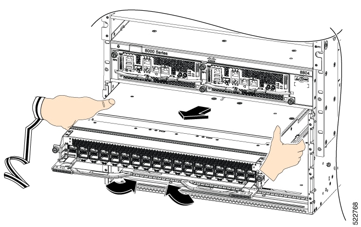
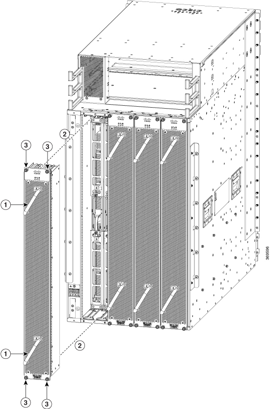
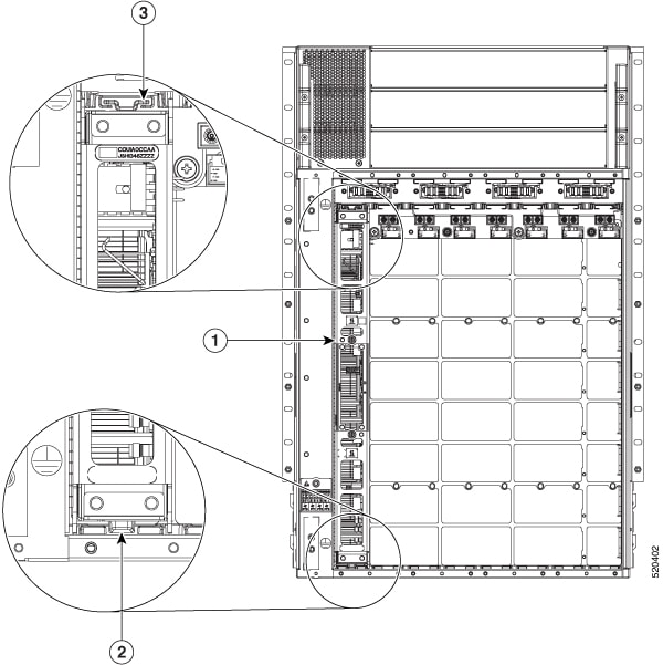
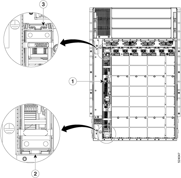
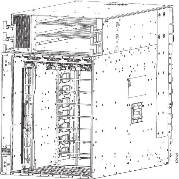
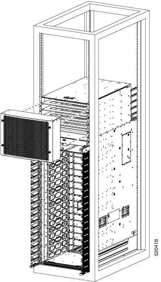
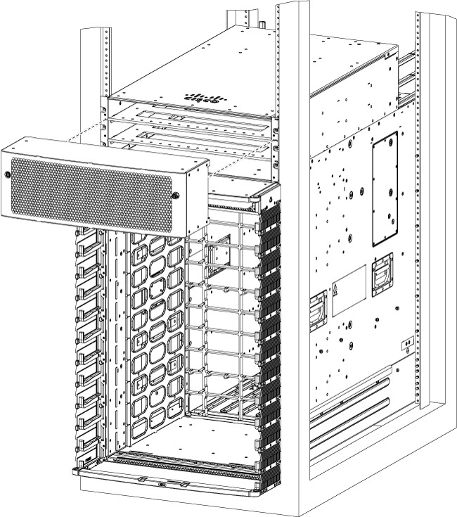
The front doors come with pre-installed air filters (8818-FILTER, 8812-FILTER, 8808-FILTER, or 8804-FILTER). If air filters need a replacement, follow this procedure.

Procedure


Step 1

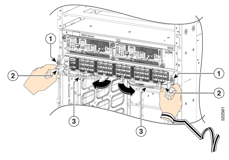
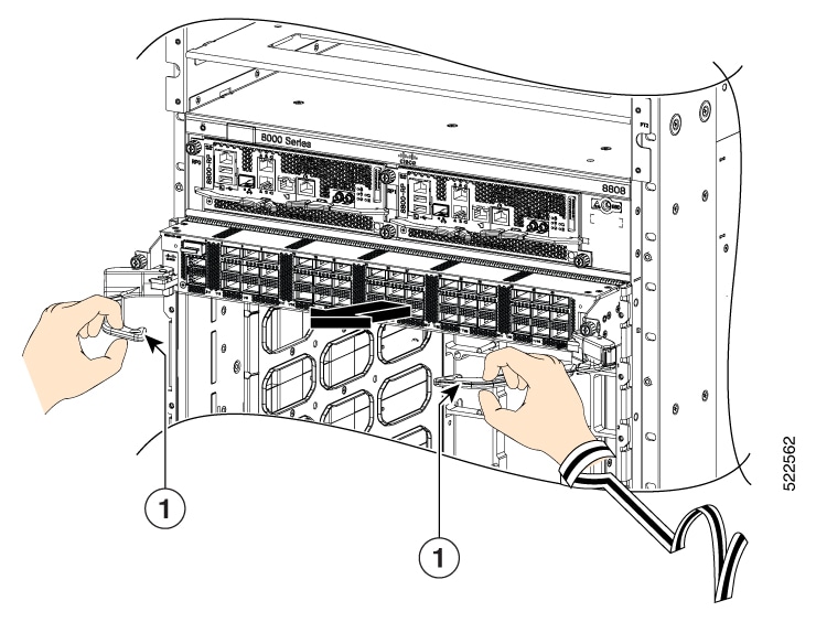
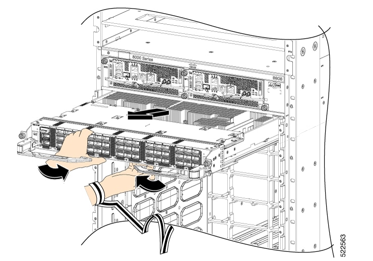
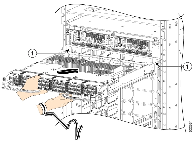
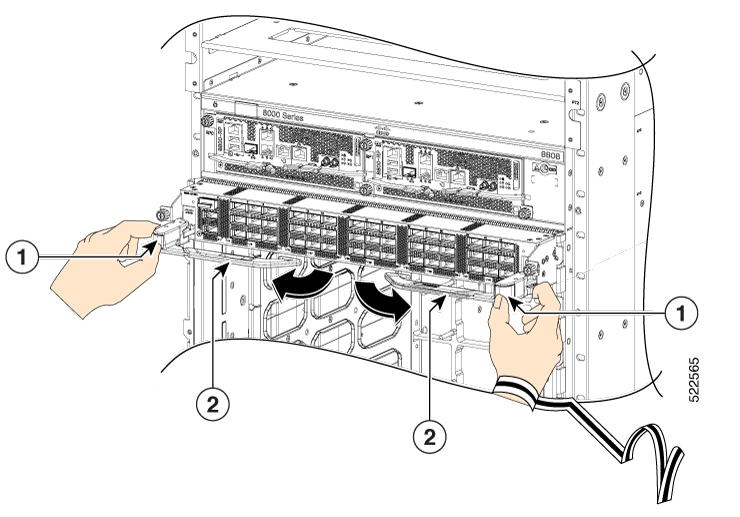
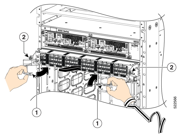
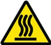
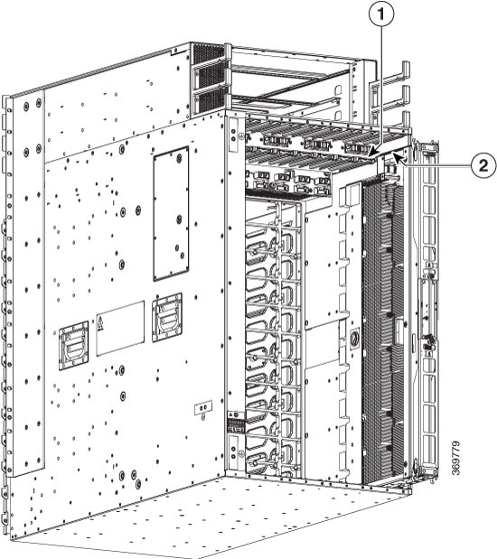
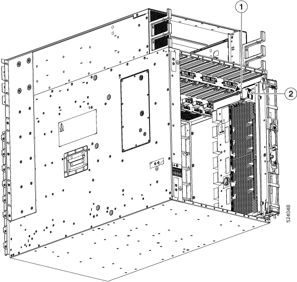
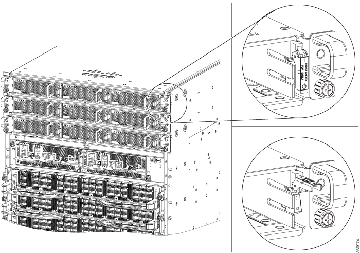
Remove the two quarter turn fasteners from the front door as shown.
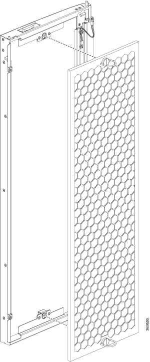
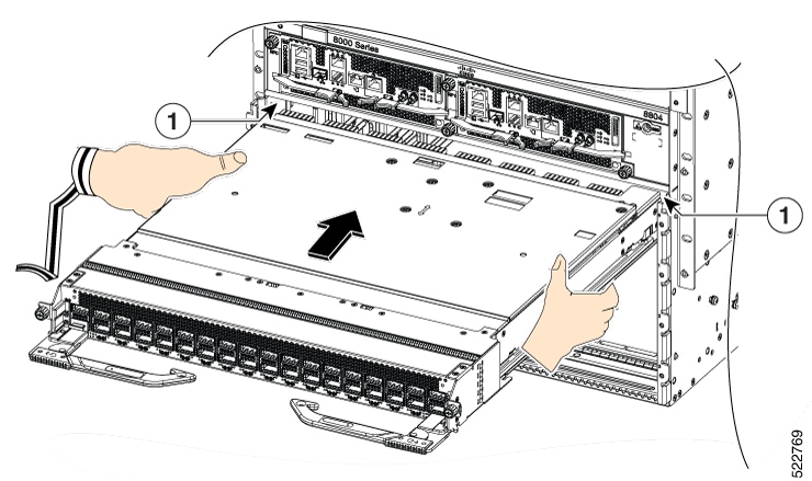
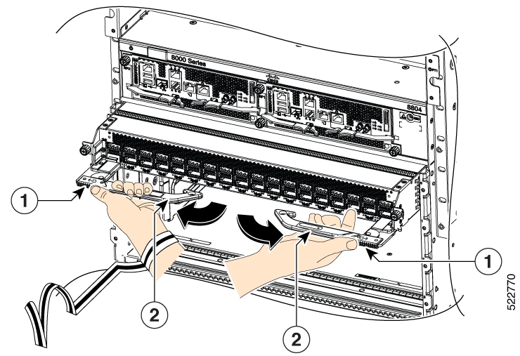
Figure 1. Replace Air Filter

Step 2

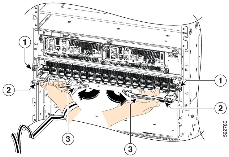
Install the new door filters on both the front doors.
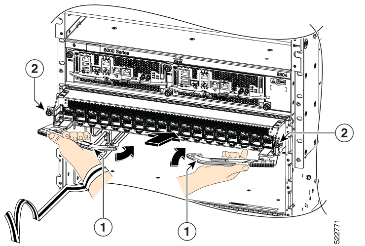
Step 3

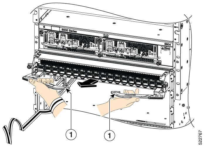
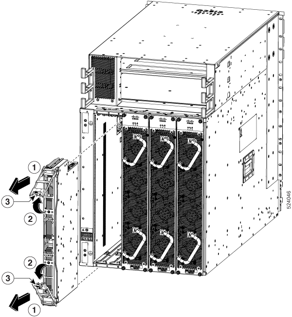
Tighten the two quarter turn fasteners back on the doors.


Provision of Grace Period Before Route Processor Shutdown from Ejector Lever

Table 1. Feature History Table

Feature Name

Release Information

Feature Description

Provision of Grace Period Before Route Processor Shutdown from Ejector Lever

Release 7.3.1

Unlatching the ejector lever of any card that is in operational state, triggers a graceful shutdown of that card.

With this release, the active RP card is enabled with a grace period of 15 seconds before it shuts down. In the event the ejector lever is unlatched, or for any other reason, you have 15 seconds to relatch the ejector lever and return the active RP back to its operational state.

The hw-module ejector close wait command is introduced for this feature.

Earlier, unlatching the ejector lever from the latch lock immediately would trigger a graceful shutdown of the Route Processor if the card is in the operational state. However, after enabling this feature, the active RP card has a grace period of 15 seconds before shutdown.

If the ejector lever is latched back within this grace period, then the card returns to the operational state. This feature, therefore, provides the option of closing the ejector lever without triggering a shutdown. This feature is especially useful when an ejector lever is accidentally unlatched.

This feature is supported only on a route processor card.

If the ejector is unlatched when card is in a status other than operational state then the grace period feature will not be supported.


Caution


When you enable this feature, do not remove the RP during the 15-second grace period. Remove the RP only in either of the following two ways:

  • Allow the RP to shut down after the 15-second grace period, then remove the RP.

  • Close the ejector lever within the 15-second grace period, then remove the RP gracefully (shutdown the RP first) or ungracefully.


LED Status

The RP status LED blinks twice with one second gap until the grace period is over.

Enabling Grace Period Before Shutting down a RP Card

This task explains how to enable grace period before shutting down a RP card:

Router(config)# hw-module ejector close wait
Router(config)# commit
Router(config)# end

The configuration is applied only on the active RP.

Use the no form of the command to remove the grace period configuration.

Router(config)# no hw-module ejector close wait

Replace a Route Processor Card

The Cisco 8818, Cisco 8812, Cisco 8808, and Cisco 8804 Routers support OIR of Route Processor (RP) cards.

The router supports up to two redundant Route Processor cards (8800-RP). When two Route Processor cards are installed in the router, one acts as an active card and the other as the standby card. When the active Route Processor card is removed, the router automatically makes the standby Route Processor card active. If the router has only one Route Processor card that is installed, a new Route Processor can be installed in the empty Route Processor slot during operation.


Warning


Statement 1029—Blank Faceplates and Cover Panels

Blank faceplates and cover panels serve three important functions: they reduce the risk of electric shock and fire, they contain electromagnetic interference (EMI) that might disrupt other equipment, and they direct the flow of cooling air through the chassis. Do not operate the system unless all cards, faceplates, front covers, and rear covers are in place.


Note


Opening the ejector levers of an installed RP card causes the RP card to shut down even when the captive screws are screwed in. To reboot the RP card, users must do one of the following:

  • Remove and reinsert the RP card and close the ejector levers.

  • Close the ejector levers and reload the card using the reload location <rack>/<{RP0 | RP1}> force command.


Replace the 8800-RP Card

The following figure describes the components used in the Route Processor installation procedure.

Figure 2. Route Processor Card Components

1

Latch Lock

3

Latching Mechanism

2

Ejector Lever Handle

4

Captive Screw


Caution


Unlatching the right ejector lever, so that it disengages from the latch lock (Callout 1 in the previous figure) triggers graceful shutdown of the Route Processor (RP) if the card is up. If the card shuts down, then wait for the RP LED to turn off before proceeding.

Moving the latch to the side doesn't disengage the latch from the lock. This is a safeguard mechanism if an operator-initiated shutdown of the route processor hasn't been performed before opening the levers. The ejector open will be logged.


  1. Open the packaging for the new RP card. Inspect the card for damage, and verify that the card is the same type as the other RP card installed in the chassis. Carefully inspect the backplane connector of the chassis and RP.


    Note


    If the card is damaged, alert the Technical Assistance Center (TAC).


  2. If you're installing the card in an empty slot, remove the blank card that is already in that slot by unscrewing its captive screw and pulling it out of the slot.

  3. If you're replacing a card that is currently in the chassis, remove the existing card from the chassis by following these steps:

    1. Run the shutdown location 0/ {RP0 | RP1} command in EXEC mode, which gracefully shuts down the Route Processor module to prevent any of the file systems from being corrupted.

    2. Verify that the Route Processor Status LED for the slot that you specified turns to Amber. Also, you can use the show platform command to verify that the status of the card is SHUT DOWN.

    3. Disconnect the cables from the card.

    4. If there are any external drives attached to the card through its USB ports, detach those drives.

    5. Loosen the two captive screws (one on each side of the RP) until the screws are no longer in contact with the chassis.

    6. Slide the latch on each of the ejector levers outwards from the lever center (see Callout 1 in the following figure).


      Attention


      This action disengages the ejector levers from the faceplate.


      Figure 3. Remove Route Processor Card from Chassis
    7. Pull to rotate the levers away from the front of the card (see Callout 2 in the previous figure).

      The card unseats its connectors from the midplane and moves slightly out of the chassis.

    8. Use one hand to hold the front of the card. Place your other hand under the card to support its weight. Pull the card out of the chassis, and set it on an antistatic surface or inside an antistatic bag.


      Note


      While performing OIR of the card, wait for 30 seconds before inserting the same or new card in the same slot. This allows the card to boot properly and reach an operational state.


Install a New 8800-RP Card

To install a new card, follow these steps:

  1. If any of the ejector levers are in closed position, slide the latch on the ejector lever outwards from the lever center. Then, pull to rotate the lever away from the front of the card.

    This action opens the lever so that the card can be fully inserted into the slot.

  2. Hold the front of the card with one hand and place your other hand under the card to support its weight.


    Note


    Ensure that you hold the route processor card parallel to the chassis while inserting it. Inserting the route processor card at an angle may damage the card's PCB.


  3. Align the back of the card to the guides in the open Route Processor slot and slide the card all the way into the slot.

    The card stops when its front is about 0.25 inches (0.6 cm) outside the front of the chassis.

  4. Rotate the levers firmly all the way to the front of the chassis. Then firmly push the tip of the lever towards the faceplate until the latch hook locks in place behind the faceplate. You may hear a click or see the latch engage. (See Callout 1 in the following figure.)

    Ensure that the other end of both levers engages behind the latching slot on the faceplate so that the card fully seats onto the connectors on the midplane.


    Note


    To confirm that the card is installed properly, pull the black tip of each ejector lever lightly, and ensure that the lever doesn't pop out.


    Figure 4. Install Route Processor Card into Chassis
  5. Screw in the two captive screws to secure the card to the chassis. Tighten the screws to 8 in-lb (0.9 N·m) of torque.

  6. Attach the cables to the card.

  7. Verify that the Route Processor card status LEDs turn on and appear green.

Replace the 8800-RP2 Card

The following figure describes the components used in the Route Processor (8800-RP2) installation procedure.

Figure 5. Route Processor Card (8800-RP2) Components

1

Ejector Lever Handles

2

Captive Screws


Caution


Unlatching the right ejector lever handle, so that it disengages from the latch lock (Callout 1 in above figure) triggers graceful shutdown of the Route Processor if the card is up. If the card shuts down, then wait for the Route Processor status LED to turn off before proceeding.

Unscrewing the captive screw doesn't disengage the latch from the lock. This is a safeguard mechanism if an operator-initiated shutdown of the route processor hasn't been performed before opening the levers. The ejector open will be logged.


  1. Open the packaging for the new Route Processor card, inspect the card for damage, and verify that the card is the same type as the other Route Processor card installed in the chassis.

    If the card is damaged, alert the Technical Assistance Center (TAC). For more information, see More Hardware Components.

  2. If you're installing the card in an empty slot, remove the blank card that is already in that slot by unscrewing its captive screws and pulling it out of the slot.

  3. If you're replacing a card that is currently in the chassis, remove the existing card from the chassis by following these steps:

    1. Run the shutdown location 0/ {RP0 | RP1} command in EXEC mode, which gracefully shuts down the Route Processor module to prevent any of the file systems from being corrupted.

    2. Verify that the Route Processor Status LED for the slot that you specified turns to Amber. Also, you can use the show platform command to verify that the status of the card is SHUT DOWN.

    3. Disconnect the cables from the card.

    4. If there are any external drives attached to the card through its USB ports, detach those drives.

    5. Loosen the two captive screws (one on each side of the RP) until the screws are no longer in contact with the chassis.

    6. Unscrew the captive screws on each of the ejector levers (see Callout 1 in the following figure).

      This action disengages the ejector levers from the faceplate.

      Figure 6. Remove Route Processor Card (8800-RP2) from Chassis

      1

      Rotate the captive screws

      2

      Pull to rotate the levers away from the card

    7. Pull to rotate the levers away from the front of the card (see Callout 2 in the previous figure).

      The card unseats its connectors from the midplane and moves slightly out of the chassis.

    8. Use one hand to hold the front of the card, place your other hand under the card to support its weight, pull the card out of the chassis, and set it on an antistatic surface or inside an antistatic bag.


      Note


      While performing OIR of the card, wait for 30 seconds before inserting the same or new card in the same slot. This allows the card to boot properly and reach an operational state.


Install an 8800-RP2 Card

To install a new card, follow these steps:

  1. If any of the ejector levers are in closed position, slide the latch on the ejector lever outwards from the lever center and pull to rotate the lever away from the front of the card.

    If the ejector levers are in closed position, unscrew the captive screw that’s holding the ejector levers closed.

  2. Hold the front of the card with one hand and place your other hand under the card to support its weight.


    Note


    Ensure that you hold the route processor card parallel to the chassis while inserting it. Inserting the route processor card at an angle may damage the card's PCB.

    Figure 7. Hold RP Card Parallel to Chassis

    1

    Route processor card (8800-RP2)

  3. Align the back of the card to the guide pin in the open Route Processor slot and slide the card all the way into the slot.

  4. Rotate the levers firmly all the way to the front of the chassis. Then firmly push the tip of the lever towards the faceplate until the latch hook locks in place behind the faceplate. (See Callout 1 in the following figure.)

    Ensure that the other end of both levers engages behind the latching slot on the faceplate. So that the card fully seats onto the connectors on the midplane of the chassis.


    Note


    To confirm that the card is installed properly, pull the black tip of each ejector lever lightly, and ensure that the lever doesn't pop out.


    Figure 8. Install Route Processor Card (8800-RP2) into Chassis

    1

    Push the ejector lever towards the latch lock

    2

    After the ejector lever locks in place, rotate the captive screws

    3

    Latch lock

  5. Screw in the two captive screws to secure the card to the chassis. Tighten the screws as shown in the following figure and apply the torque as mentioned in the Torque recommendation section:

    Figure 9. Tighten the Screws in Order

    Torque recommendation:

    • Hand-tighten all the four captive screws.

    • Torque all the four screws to 4 in-lbs (0.45 N·m) in the sequence as shown in the figure.

    • Torque another 4 in-lbs (0.45 N·m) to the captive screws such that the total torque applied becomes 8 in-lbs (0.9 N·m). Follow the same sequence as shown in the figure.


    Important


    The total torque must not be more than 8 in-lbs.


  6. Attach the cables to the card.

  7. Verify that the Route Processor card status LEDs turn on and appear green.

Replace the 8800-RP2-S Card

The following figure describes the components used in the Route Processor (8800-RP2-S) installation procedure.

Figure 10. Route Processor Card (8800-RP2-S) Components

1

Ejector Lever Handles

2

Captive Screws


Caution


Unlatching the right ejector lever handle, so that it disengages from the latch lock (Callout 1 in above figure) triggers graceful shutdown of the Route Processor if the card is up. If the card shuts down, then wait for the Route Processor status LED to turn off before proceeding.

Unscrewing the captive screw doesn't disengage the latch from the lock. This is a safeguard mechanism if an operator-initiated shutdown of the route processor hasn't been performed before opening the levers. The ejector open will be logged.


  1. Open the packaging for the new Route Processor card, inspect the card for damage, and verify that the card is the same type as the other Route Processor card installed in the chassis.

    If the card is damaged, alert the Technical Assistance Center (TAC). For more information, see More Hardware Components.

  2. If you're installing the card in an empty slot, remove the blank card that is already in that slot by unscrewing its captive screws and pulling it out of the slot.

  3. If you're replacing a card that is currently in the chassis, remove the existing card from the chassis by following these steps:

    1. Run the shutdown location 0/ {RP0 | RP1} command in EXEC mode, which gracefully shuts down the Route Processor module to prevent any of the file systems from being corrupted.

    2. Verify that the Route Processor Status LED for the slot that you specified turns to Amber. Also, you can use the show platform command to verify that the status of the card is SHUT DOWN.

    3. Disconnect the cables from the card.

    4. If there are any external drives attached to the card through its USB ports, detach those drives.

    5. Loosen the two captive screws (one on each side of the RP) until the screws are no longer in contact with the chassis.

    6. Unscrew the captive screws on each of the ejector levers (see Callout 1 in the following figure).

      This action disengages the ejector levers from the faceplate.

      Figure 11. Remove Route Processor Card (8800-RP2-S) from Chassis

      1

      Rotate the captive screws

      2

      Pull to rotate the levers away from the card

    7. Pull to rotate the levers away from the front of the card (see Callout 2 in the previous figure).

      The card unseats its connectors from the midplane and moves slightly out of the chassis.

    8. Use one hand to hold the front of the card, place your other hand under the card to support its weight, pull the card out of the chassis, and set it on an antistatic surface or inside an antistatic bag.


      Note


      While performing OIR of the card, wait for 30 seconds before inserting the same or new card in the same slot. This allows the card to boot properly and reach an operational state.


Install an 8800-RP2-S Card

To install a new card, follow these steps:

  1. If any of the ejector levers are in closed position, slide the latch on the ejector lever outwards from the lever center and pull to rotate the lever away from the front of the card.

    If the ejector levers are in closed position, unscrew the captive screw that’s holding the ejector levers closed.

  2. Hold the front of the card with one hand and place your other hand under the card to support its weight.


    Note


    Ensure that you hold the route processor card parallel to the chassis while inserting it. Inserting the route processor card at an angle may damage the card's PCB.

    Figure 12. Hold RP Card Parallel to Chassis

    1

    Route processor card (8800-RP2-S)

  3. Align the back of the card to the guide pin in the open Route Processor slot and slide the card all the way into the slot.

  4. Rotate the levers firmly all the way to the front of the chassis. Then firmly push the tip of the lever towards the faceplate until the latch hook locks in place behind the faceplate. (See Callout 1 in the following figure.)

    Ensure that the other end of both levers engages behind the latching slot on the faceplate. So that the card fully seats onto the connectors on the midplane of the chassis.


    Note


    To confirm that the card is installed properly, pull the black tip of each ejector lever lightly, and ensure that the lever doesn't pop out.


    Figure 13. Install Route Processor Card (8800-RP2-S) into Chassis

    1

    Push the ejector lever towards the latch lock

    2

    After the ejector lever locks in place, rotate the captive screws

    3

    Latch lock

  5. Screw in the two captive screws to secure the card to the chassis. Tighten the screws as shown in the following figure and apply the torque as mentioned in the Torque recommendation section:

    Figure 14. Tighten the Screws in Order

    Torque recommendation:

    • Hand-tighten all the four captive screws.

    • Torque all the four screws to 4 in-lbs (0.45 N·m) in the sequence as shown in the figure.

    • Torque another 4 in-lbs (0.45 N·m) to the captive screws such that the total torque applied becomes 8 in-lbs (0.9 N·m). Follow the same sequence as shown in the figure.


    Important


    The total torque must not be more than 8 in-lbs.


  6. Attach the cables to the card.

  7. Verify that the Route Processor card status LEDs turn on and appear green.


Note


The router doesn't support migration from the 8800-RP2 to 8800-RP2-S card.


Migrating from 8800-RP to 8800-RP2 Card

Before you begin:

  • You must have console access to the router.

  • The router must be running Cisco IOS XR software release 7.11.1 or later version.

  • The router must have two Route Processors (RP) cards, active and standby, up and running.

Procedure


Step 1

Use the show platform command to verify that all the router nodes are up and running.

Step 2

Use the show redundancy summary command to verify that the active RP and standby RP are in the NSR-ready State.

Example:


Router# show redundancy summary 
Wed Jun 17 11:18:51.391 PST 
Active/Primary Standby/Backup 
-------------- -------------- 
0/RP0/CPU0(A)  0/RP1/CPU0(S) (Node Ready, NSR: Ready) 
0/RP0/CPU0(P)  0/RP1/CPU0(B) (Proc Group Ready, NSR: Ready) 

Router# show redundancy 

Wed Jun 17 11:20:19.086 PST 
Redundancy information for node 0/RP1/CPU0: 
========================================== 
Node 0/RP1/CPU0 is in ACTIVE role 
Node Redundancy Partner (0/RP0/CPU0) is in STANDBY role 
Standby node in 0/RP0/CPU0 is ready 
Standby node in 0/RP0/CPU0 is NSR-ready 
Node 0/RP1/CPU0 is in process group PRIMARY role 
Process Redundancy Partner (0/RP0/CPU0) is in BACKUP role 
Backup node in 0/RP0/CPU0 is ready 
Backup node in 0/RP0/CPU0 is NSR-ready 

Group             Primary     Backup    Status 
---------         ---------   --------- --------- 
v6-routing        0/RP1/CPU0  0/RP0/CPU0  Ready 
mcast-routing     0/RP1/CPU0  0/RP0/CPU0  Ready 
netmgmt           0/RP1/CPU0  0/RP0/CPU0  Ready 
v4-routing        0/RP1/CPU0  0/RP0/CPU0  Ready 
central-services  0/RP1/CPU0  0/RP0/CPU0  Ready 
dlrsc             0/RP1/CPU0  0/RP0/CPU0  Ready 
dsc               0/RP1/CPU0  0/RP0/CPU0  Ready 
 
Active node reload "Cause: Initiating switch-over." 
Standby node reload "Cause: Initiating switch-over."

Step 3

Remove the standby RP (8800-RP) card from slot1. Follow the procedure explained in the topic Replace a Route Processor Card.

Step 4

Insert RP2 (8800-RP2) card in slot1. Follow the procedure explained in the topic Install an 8800-RP2 Card.

Step 5

Wait until the standby RP card reach NSR-ready state and status of ALL the groups is Ready state. Use show redundancy command to verify the same.

Step 6

Reload the active RP by using the reload location 0/RP0/CPU0 command. Executing the command makes the 8800-RP2 card in slot1 the active card.

Step 7

Verify that the active RP is 8800-RP2 and that it is in the NSR-ready state. Verify that 8800-RP2 has the running configuration from 8800-RP.

Example:


Router# show redundancy summary
Router# show running config 

Step 8

Remove the standby RP (8800-RP) from slot0. Follow the procedure explained in step-3.

Step 9

Insert the RP (8800-RP2) in slot0. Follow the procedure explained in step-4.

Step 10

Verify that the active RP card reach NSR-ready state and status of ALL the groups is Ready state. Use show redundancy command to verify the same.

Note


If you want to migrate to 8800-RP from 8800-RP2, follow the same steps as mentioned in this procedure, Migrating from 8800-RP to 8800-RP2 Card.


Migrating from 8800-RP to 8800-RP2-S Card

Before you begin:

  • You must have console access to the router.

  • The router must be running Cisco IOS XR software release 24.4.1 or later version.

  • The router must have two RP1 cards (active and standby) up and running.

Procedure


Step 1

Use the show platform command to verify that all the router nodes are up and running.

Step 2

Use the show redundancy summary command to verify that the active RP and standby RP are in the NSR-ready State.

Example:


Router# show redundancy summary 
Wed Jun 17 11:18:51.391 PST 
Active/Primary Standby/Backup 
-------------- -------------- 
0/RP0/CPU0(A)  0/RP1/CPU0(S) (Node Ready, NSR: Ready) 
0/RP0/CPU0(P)  0/RP1/CPU0(B) (Proc Group Ready, NSR: Ready) 

Router# show redundancy 

Wed Jun 17 11:20:19.086 PST 
Redundancy information for node 0/RP1/CPU0: 
========================================== 
Node 0/RP1/CPU0 is in ACTIVE role 
Node Redundancy Partner (0/RP0/CPU0) is in STANDBY role 
Standby node in 0/RP0/CPU0 is ready 
Standby node in 0/RP0/CPU0 is NSR-ready 
Node 0/RP1/CPU0 is in process group PRIMARY role 
Process Redundancy Partner (0/RP0/CPU0) is in BACKUP role 
Backup node in 0/RP0/CPU0 is ready 
Backup node in 0/RP0/CPU0 is NSR-ready 

Group             Primary     Backup    Status 
---------         ---------   --------- --------- 
v6-routing        0/RP1/CPU0  0/RP0/CPU0  Ready 
mcast-routing     0/RP1/CPU0  0/RP0/CPU0  Ready 
netmgmt           0/RP1/CPU0  0/RP0/CPU0  Ready 
v4-routing        0/RP1/CPU0  0/RP0/CPU0  Ready 
central-services  0/RP1/CPU0  0/RP0/CPU0  Ready 
dlrsc             0/RP1/CPU0  0/RP0/CPU0  Ready 
dsc               0/RP1/CPU0  0/RP0/CPU0  Ready 
 
Active node reload "Cause: Initiating switch-over." 
Standby node reload "Cause: Initiating switch-over."

Step 3

Remove the standby RP (8800-RP) card from slot1. Follow the procedure explained in the topic Replace a Route Processor Card.

Step 4

Insert 8800-RP2-S card in slot1. Follow the procedure explained in the topic Install an 8800-RP2-S Card.

Step 5

Wait until the standby RP card reach NSR-ready state and status of ALL the groups is Ready state. Use show redundancy command to verify the same.

Step 6

Reload the active RP by using the reload location 0/RP0/CPU0 command. Executing the command makes the 8800-RP2-S card in slot1 the active card.

Step 7

Verify that the active RP is 8800-RP2-S and that it is in the NSR-ready state. Verify that 8800-RP2-S has the running configuration from 8800-RP.

Example:


Router# show redundancy summary
Router# show running config 

Step 8

Remove the standby RP, 8800-RP, from slot0. Follow the procedure explained in step-3.

Step 9

Insert the 8800-RP2-S in slot0. Follow the procedure explained in step-4.

Step 10

Verify that the active RP card reach NSR-ready state and status of ALL the groups is Ready state. Use show redundancy command to verify the same.

Note


If you want to migrate to 8800-RP from 8800-RP2-S, follow the same steps as mentioned in this procedure, Migrating from 8800-RP to 8800-RP2-S Card.


Replace a Line Card

The Cisco 8800 series routers can operate with one or more line cards. If there is at least one line card that is installed and operating in the chassis, you can replace another line card or install a new line card in an empty line card slot.

The Cisco 8800 series routers support OIR of line cards.


Note


You must install at least one route processor card when you power on the router.

Cisco 8800 series line cards use either buttons or latches to lock the ejector levers.

Watch Replace a Line Card (Video).

Replace or Install a Line Card - Ejector Levers with Buttons


Warning


Statement 1029—Blank Faceplates and Cover Panels

Blank faceplates and cover panels serve three important functions: they reduce the risk of electric shock and fire, they contain electromagnetic interference (EMI) that might disrupt other equipment, and they direct the flow of cooling air through the chassis. Do not operate the system unless all cards, faceplates, front covers, and rear covers are in place.


Warning


Statement 1051—Laser Radiation

Invisible laser radiation may be emitted from disconnected fibers or connectors. Do not stare into beams or view directly with optical instruments.


Caution


  • Line cards have two ejector levers to release the card from the router. Use these levers to remove the line card and to seat the line card firmly in the router when you are installing the line card. The ejector levers align and seat the card connectors in the router. To avoid damaging card mechanical components, never carry a line card by the captive installation screws or ejector levers. Doing so can damage these components and cause card insertion problems.

  • Ensure that all the line card screws are fully tightened. Failure to properly tighten the line card screws may result in fabric links not coming up.

  • Rotate the ejector levers toward the faceplate past parallel until it stops. This ensures that the line card fully inserts when you install the line card.


Note


Opening the ejector levers of an installed line card causes the line card to shut down even when the captive screws are screwed in. To reboot the line card, you must do one of the following:

  • Remove and reinsert the line card and close the ejector levers.

  • Close the ejector levers and reload the card using the reload location <rack>/<line-card-slot> force command.


Procedure


Step 1

Open the packaging for the new line card and inspect the line card for damage. Carefully inspect the fabric connectors for damage.

If the line card is damaged, contact the Technical Assistance Center (TAC).

Step 2

If you are replacing a line card that is currently in the chassis, remove the existing line card from the chassis by following these steps:

  1. Run the shutdown location 0/ location/CPU0 command, which gracefully shuts down the line card.

  2. Verify that the Line Card LED for the slot that you specified turns off. Also, you can use the show platform command to verify that the status of the card is SHUT DOWN.

  3. Disconnect and label each of the interface cables from the line card.

  4. Loosen the two captive screws.

  5. Press the ejector buttons and the two ejector levers open in the direction as shown in the image below.

    Figure 15. Press the Ejector Buttons

    1

    Captive screws

    3

    Ejector levers

    2

    Ejector buttons

  6. Use the ejector levers to pull the line card a couple of inches (about 5 cm) from the chassis.

    Figure 16. Pull the Line Card from the Chassis

    1

    Ejector levers

  7. Close the ejector levers in the direction as shown in the image below. Use one hand to hold the front of the line card, place your other hand under the line card to support its weight, pull it out of the chassis, and set it on an antistatic surface or inside an antistatic bag. Or, place your hands on the sides of the line card, pull it out of the chassis, and set it on an antistatic surface or inside an antistatic bag.

    Figure 17. Remove the line card from the chassis

Step 3

To install the line card, follow these steps:

  1. Hold the front of the line card with one hand and place your other hand under the line card to support its weight. Or, place your hands on the sides of the line card, pull it out of the chassis, and set it on an antistatic surface or inside an antistatic bag.

  2. Align the back of the line card to the guides in the open line card slot and slide the line card all the way into the slot (see the following figure).

    Figure 18. Insert a Line Card into the Chassis

    1

    Guides (line card slot)

    The line card stops when its front is about 0.25 inches (0.6 cm) outside the front of the chassis. Press the ejector buttons, and the two levers move partway from the center of the line card in the direction as shown in the image.

    Figure 19. Press the Ejector Buttons

    1

    Ejector buttons

    2

    Ejector levers

  3. Close the ejectors by rotating the ends of the two levers toward the faceplate past parallel until it stops. This ensures that the line card fully inserts when you install it.

    Figure 20. Close the Ejector Levers

    1

    Ejector levers

    2

    Captive screws

    Note


    As you rotate the levers, the front of the line card moves all the way to the front of the chassis and the line card fully seats on the chassis.

  4. Tighten the two captive screws to 8 in-lb (0.9 Nm) torque.

    Note


    When installing a line card, fully tighten both captive installation screws to ensure that the card is correctly seated in the router. A card that is only partially seated in the router might not operate properly, even if it boots.

  5. Attach each interface cable to the appropriate port on the line card. Use the label on each cable to determine which port each cable attaches to.

  6. Verify that the line card LEDs turn on and appear green.


Replace or Install a Line Card - Ejector Levers with Latches


Warning


Statement 1029—Blank Faceplates and Cover Panels

Blank faceplates and cover panels serve three important functions: they reduce the risk of electric shock and fire, they contain electromagnetic interference (EMI) that might disrupt other equipment, and they direct the flow of cooling air through the chassis. Do not operate the system unless all cards, faceplates, front covers, and rear covers are in place.


Warning


Statement 1051—Laser Radiation

Invisible laser radiation may be emitted from disconnected fibers or connectors. Do not stare into beams or view directly with optical instruments.


Caution


  • Line cards have two ejector levers to release the card from the router. Use these levers to remove the line card and to seat the line card firmly in the router when you are installing the line card. The ejector levers align and seat the card connectors in the router. To avoid damaging card mechanical components, never carry a line card by the captive installation screws or ejector levers. Doing so can damage these components and cause card insertion problems.

  • Ensure that all the line card screws are fully tightened. Failure to properly tighten the line card screws may result in fabric links not coming up.

  • Rotate the ejector levers towards the faceplate past parallel until it stops. This ensures that the line card fully inserts when you install the line card.


Note


Opening the ejector levers of an installed line card causes the line card to shut down even when the captive screws are screwed in. To reboot the line card, users must do one of the following:
  • Remove and reinsert the line card and close the ejector levers.

  • Close the ejector levers and reload the card using the reload location rack line-card-slot i force command.


Procedure


Step 1

Open the packaging for the new line card and inspect the line card for damage.

If the line card is damaged, contact the Technical Assistance Center (TAC).

Step 2

If you are replacing a line card that is currently in the chassis, remove the existing line card from the chassis by following these steps:

  1. Run the shutdown location 0/ location/CPU0 command, which gracefully shuts down the line card.

  2. Verify that the Line Card LED for the slot that you specified turns off. Also, you can use the show platform command to verify that the status of the card is SHUT DOWN.

  3. Disconnect and label each of the interface cables from the line card.

  4. Loosen the two captive screws.

    Note

     
    You must loosen the two captive screws completely before using the ejector levers to remove the line card. Failure to loosen the captive screws can cause damage to the ejector levers.
  5. Slide the ejector lever latches outward and pull the two ejector levers in the direction as shown in the image below.

    Figure 21. Slide the Ejector Lever Latches

    1

    Captive screws

    3

    Ejector levers

    2

    Ejector lever latches

  6. Use the ejector levers to pull the line card a couple of inches (about 5 cm) from the chassis.

    Figure 22. Pull the Line Card from the Chassis

    1

    Ejector levers

  7. Close the ejector levers. The ejector lever latches will lock the ejector levers closed.

  8. Place your hands on the sides of the line card, pull it out of the chassis, and set it on an antistatic surface or inside an antistatic bag.

    Figure 23. Remove the Line Card from the Chassis

Step 3

To install the line card, follow these steps:

  1. Hold the sides of the line card with both hands to support its weight.

  2. Align the back of the line card to the guides in the open line card slot and slide the line card all the way into the slot (see the following figure).

    Figure 24. Insert a Line Card into the Chassis

    1

    Guides (line card slot)

    The line card stops when its front is about 0.25 inches (0.6 cm) outside the front of the chassis.

  3. Slide the ejector lever latches to unlock the ejector levers and open the ejector levers outward as shown in the image.

    Figure 25. Unlock the Ejector Levers

    1

    Ejector lever latches

    2

    Ejector levers

  4. While holding the elector levers in the open position, slide the line card further into the slot until the ejector levers engage with the sides of the line card slot.

  5. To fully seat the line card, close the ejectors by rotating the ends of the two levers toward the faceplate past parallel until it stops. This ensures that the line card fully inserts when you install it.

    Figure 26. Close the Ejector Levers

    1

    Ejector levers

    2

    Captive screws

    Note

     
    As you rotate the levers, the front of the line card moves all the way to the front of the chassis and the line card fully seats on the chassis.
  6. Tighten the two captive screws to 8 in-lb (0.9 Nm) torque.

    Note

     
    When installing a line card, fully tighten both captive installation screws to ensure that the card is correctly seated in the router. A card that is only partially seated in the router might not operate properly, even if it boots.
  7. Attach each interface cable to the appropriate port on the line card. Use the label on each cable to determine which port each cable attaches to.

  8. Verify that the line card LEDs turn on and appear green.


Replace a Fan Tray

You can remove a fan tray (8818-FAN, 8812-FAN, 8808-FAN, or 8804-FAN) to either replace it with another fan tray or to replace a fabric card located behind it.

The router uses four fan trays but it can operate with three fan trays while you replace one or remove one to replace one of the fabric cards behind the fan tray. When you remove one fan tray, the other fan trays speed up their fans to maintain the designed airflow.


Note


Fan trays marked with a blue dot have no impact on installation steps or airflow direction.


Note


To ensure adequate airflow and prevent overheating, do not operate the router with three fan trays for more than 10 minutes.


Caution


Never remove two fan trays at a time during operation, the router allows up to two minutes of operations before shutting down unless you replace the missing fan tray within that time. If the router senses an over temperature condition when multiple fan trays are removed, the shutdown can occur in less than two minutes.

To replace a fan tray, you must perform the following functions:

  1. Remove the fan tray.

  2. Install a fan tray.

Watch Replace a Fan Tray (Video).

Remove Fan Tray

Remove only one fan tray at a time during router operations. If you remove more than one fan tray at a time, the router shuts down within two minutes unless you replace the extra fan trays that you removed within that time.

Procedure


Step 1

Unscrew the four captive screws on the front of the fan tray until each screw is free of the chassis.

Step 2

Hold both handles on the front of the fan tray with both of your hands and pull the fan tray out of the slot.

Step 3

Set the fan tray on antistatic material or inside an antistatic bag.


Install Fan Tray

Before you begin

  • Fan tray slot is open in the chassis.

  • If you are replacing a fabric card behind the open fan tray slot, ensure that the fabric card replacement operation is completed.

Procedure


Step 1

Use both of your hands to hold the two handles on the front of the fan tray that you are installing.

Figure 27. Remove Fan Tray from the Chassis

1

Handle

3

Captive screws

2

Align fan tray in position

Step 2

Position the fan tray with its rear (the side with the electrical connectors) at the opening for the fan tray slot in the chassis.

Step 3

Align the two tracks on the top of the fan tray with the two sets of rails at the top of the open fan tray slot in the chassis.

Step 4

Slide the fan tray all the way into the slot until the front of the fan tray touches the chassis.

Make sure that the four captive screws on the front of the fan tray align with the four screw holes in the chassis.

Step 5

Screw in the four captive screws to secure the fan tray to the chassis. Tighten the screws to 8 in-lb (0.9 N·m) of torque.

Step 6

Verify that the fan tray STATUS LED turns on and becomes green, approximately within 20 seconds.


Replace Fabric Card


Warning


Statement 1079—Hot Surface

This icon is a hot surface warning. To avoid personal injury, do not touch without proper protection.


Note


The fabric card surfaces may reach temperatures exceeding 80°C (176°F). Removal and installation of the fabric card must be performed by a skilled individual. To avoid potential burns or injuries, always wear appropriate Personal Protective Equipment (PPE), such as heat-resistant gloves rated for a minimum of 100°C (212°F), when handling the fabric card.


Note


The Cisco 8800 series routers support Online Insertion and Removal (OIR) of fabric cards only when replacing a card with the same type and speed— for example, swapping 88xx-FC with 88xx-FC or 88xx-FC0 with 88xx-FC0. If it is necessary to replace a fabric card with a different type or speed (for example, from 88xx-FC to 88xx-FC0 or vice versa), the router must be powered down prior to the replacement. Mixing different types of fabric cards in an active system is not supported and may result in system functionality issues.


The router uses either a minimum of four or a maximum of eight fabric cards but you can replace a fabric card while others are operating. To replace a fabric card with the same type, you must do each of the following:

,

  • Shut down the fabric card being replaced.

  • Remove the fan tray covering the fabric card in the chassis.


    Note


    To ensure adequate airflow and prevent overheating, do not operate the router with three fan trays for more than 10 minutes.
  • Remove the fabric card.

  • Install the new fabric card.


    Note


    We recommend that you insert the fabric cards in the sequence starting with FC0, FC1, and so on (from left to right). Use the adjacent card as a guide to retain the cards in vertical position.
  • Reinstall the fan tray over the fabric card.

  • Activate the fabric card.

The Cisco 8800 series routers support OIR of fabric card.

To maintain the designed airflow while you remove the fan tray, the fans in the other fan trays increase their speed. During operations, it is required that you remove only one fan tray at a time and reinstall that fan tray within 10 minutes to avoid the possibility of having the router overheat and shut down. If you remove more than one fan tray at a time, the router shuts down if you do not reinstall the extra missing fan trays within two minutes (the shutdown can occur earlier if the router over heats).


Note


If the router is using only five fabric cards (5fc mode), the fabric cards must be inserted in FC slots 1, 2, 3, 4, and 5.

Note


Opening the ejector levers of an installed fabric card causes the fabric card to shut down even when the captive screws are screwed in. To reboot the fabric card, users must do one of the following:

  • Remove and reinsert the fabric card and close the ejector levers.

  • Close the ejector levers and reload the fabric card using the reload location <rack>/<fabric card location> force command.


Watch Replace a Fabric Card (Video).

Remove a Fabric Card

Before you begin

  • You must wear an electrostatic discharge (ESD) wrist strap or other ESD protective device while handling modules.

  • Prepare an antistatic surface or packing materials for each module that you remove from the chassis.

Procedure


Step 1

If you are replacing a fabric card, open the packaging for the new module and inspect it for damage.

If the module is damaged, alert the Technical Assistance Center (TAC) and stop this replacement process until you have an undamaged module to install.

Step 2

To prevent loss of packets during operations, shut down the fabric card as follows:

  1. Shut the fabric control plane using the controller fabric plane <plane-id> shutdown command.

    There are eight planes and the value of the <plane-id> is between 0–7.

    When you are replacing the card, shut down the corresponding fabric plane of the card. For example, when you are replacing the card in slot 0 (0/FC0), shut down fabric plane 0.

  2. Run the shutdown location 0/FC location command.

  3. Verify that the Fabric LED for the slot that you specified turns off. Also, you can use the show platform command to verify that the status of the card is SHUT DOWN.

Step 3

Remove the fan tray covering the fabric card in the chassis.

Refer the fan tray removal procedure:Replace a Fan Tray

Step 4

Remove the fabric card that you are replacing by following these steps:

  1. Unscrew the two captive screws on the center of each of the two handles on the fabric card (see Callout 1 in the following figure).

  2. Rotate the handles outwards until they stop (see Callout 2 in the following figure).

  3. With each of the two handles in your two hands, pull the module a couple of inches (about 5 cm) out of the slot (see the following figure).

    Figure 28. Removing a Fabric Card from the Chassis
    Figure 29. Removing a Fabric Card from the Chassis - 8808-FC1

    1

    Pull on both handles to partially remove the fabric card from the chassis

    3

    Two captive screws (one on each handle)

    2

    Rotate both ejector handles to the front of the module

  4. Place one hand under the fabric card to support its weight, place your other hand on the front of the module, and slide the module out of the slot.

  5. Rotate both handles back to the front of the module until they are in place. Fasten each handle to the module using the captive screw on the back of the handle. Hand tighten the handle screws to keep them in place for carrying the card.

  6. Rotate the module 90 degrees and lay it flat on an antistatic surface or in an antistatic bag.


Install a Fabric Card

Procedure


Step 1

Unscrew the two captive screws (one on each ejector handle) and rotate the ejector handles at least 30 degrees. Ensure that the locking posts on the top and bottom of the chassis rotate into the module so that the module can slide fully into the slot.

Step 2

Place one hand on the front of the module and turn the module 90 degrees so that the electrical connectors are on the bottom.

Step 3

Align the guide bar on the bottom of the fabric card into the guide slot at the bottom of the fabric card slot, and make sure that the guide rails on the top of the fabric card align with the track on the top of the slot.

Note

 
The lower guide rail extends to the back of the chassis. The upper guide rail does not connect until the card is halfway into the chassis.
Figure 30. Install Fabric Card
Figure 31. Install Fabric Card - 8808-FC1

1

Always install the fabric card in a vertical position

2

Guide bar and guide slot

3

Guide rail and track

Figure 32. Installing a Fabric Card
Figure 33. Installing a Fabric Card - 8808-FC1

1

Chassis top fabric card guide rail.

2

Insert fabric card top guide rail into chassis top fabric card guide rail.

Figure 34. Fabric Card Installed in a Chassis
Figure 35. Fabric Card Installed in a Chassis - 8808-FC1

Step 4

Slide the module all the way into the slot.

Step 5

Rotate both ejector levers to 90 degrees to the front of the chassis and be sure that the module is locked to the top and bottom of the slot.

Step 6

Tighten the captive screw on each of the two levers to 8 in-lb (0.9 N-m) of torque, so that each lever is locked in place on the module.

Step 7

Verify the fabric card LEDs become green.

Step 8

Reinstall the fan tray over the fabric card.

Refer the installing the fan tray procedure: Install Fan Tray

Step 9

Run the reload location 0/location/CPU0 command.

Step 10

Wait for the fabric card to become operational. Use the show platform | inc FC command to verify the status.

Note

 
The fabric card must be operational before resetting the fabric plane.

Step 11

Reset the fabric control plane using the no controller fabric plane <plane-id> shutdown command

Step 12

Verify that the Fabric LED for the slot that you specified turns on. Also, you can verify that the card is in power on state by running the show platform command to verify the status of the card to be POWERED_ON.

Since the Fan trays are blocking the view, Fabric card LEDs might not be visible. Therefore, you can verify the Fabric card LEDs status using show led location 0/FClocation command.


Replace Power Supply Components

The Cisco 8800 series routers support OIR of power modules. If you are replacing a redundant power module, you can replace the power module while the system remains powered on without any electrical hazard or damage to the system. This feature enables you to replace a power module while the system maintains all routing information and ensures session preservation.

However, to maintain operational redundancy and proper cooling, and to meet EMI compliance standards, you must have at least one working redundant power module that is installed. When you remove a failed power module with the router in operation, perform the replacement as quickly as possible. Make sure you have the replacement power module ready before beginning the removal and installation procedure.


Note


For the RP to communicate properly to a power module in a power tray, input power to at least one of the power modules in the power tray should be present.

This section contains procedures on how to replace the power modules.


Caution


Do not turn off the switch on the power tray to remove individual power modules. Power modules support OIR, so they can be removed and replaced with the power on and the system operating.

Install Power Shelf Bezel

Follow these steps to install a power shelf bezel on a chassis:

Procedure


Place the power supply bezel as shown in the below figure and secure it with the provided jackscrews.

Figure 36. Power Supply Bezel for 8818 Chassis
Figure 37. Power Supply Bezel for 8812 Chassis
Figure 38. Power Supply Bezel for 8808 Chassis
Figure 39. Power Supply Bezel for 8804 Chassis

Replace DC Power Module

Follow these steps to remove a DC power module from the chassis.

Procedure


Step 1

Pull the handle down.

Step 2

Unscrew the screw that secures the power module using a Phillips screw driver.

Step 3

Slide the power module out of its bay while supporting it with your other hand to remove it.

Figure 40. DC Power Module

Step 4

Slide the new power module into the bay until it mates with its backplane connector.

Step 5

Move the handle up.

Step 6

Tighten the screw that secures the power module using a Phillips screw driver.

Caution

 
To prevent damage to the power tray backplane connector, do not use excessive force when inserting the power module into the power tray.

Step 7

Verify that the (green) Power Input indicator on the front of the power module goes on.


Disconnect DC Power

Procedure


Step 1

Power off the circuit breaker assigned to the DC power source you are disconnecting.

Caution


To ensure that power remains off while you are performing this procedure, lock-out/tag-out the circuit breaker switch in the STANDBY (0) position until you are ready to turn it on.

Step 2

Remove the clear plastic safety covers that fit over the DC power connection terminal studs.

Caution


To prevent injury and damage to the equipment, always remove the source DC power cables and ground from the power tray terminals in the following order : (1) negative (–), (2) positive (+).

Step 3

Disconnect the DC power cables from their terminals in the following order and note the color of each cable.

  1. Negative (PWR) cables first.

  2. Positive (RTN) cables last.

Step 4

Repeat Step 1 through Step 3 for the other power tray, if installed.

Caution


It is not necessary to disconnect all power from the router to replace components, including power modules.


Reconnect DC Power

Follow these steps to reconnect DC power to a DC power tray:

Procedure


Step 1

Set the power switch to the OFF (0) position.

Step 2

Check that the circuit breaker assigned to the DC power source you are reconnecting is powered OFF (0).

Step 3

Reconnect the DC power cables in the following order.

  1. Positive (RTN) cables first.

  2. Negative (PWR) cable last.

  3. Repeat Step 1 through Step 3 for the other power trays.

    Caution


    To prevent injury and damage to the equipment, always attach the ground and source DC power cable lugs to the power tray terminals in the following order: (1) positive (+) to positive (+), (2) negative (–) to negative (–).

    Caution


    Do not overtighten the nuts that secure the DC power cables to the power tray terminals. The nuts should be tightened using the 7/16 hex socket and torque wrench to a torque of 45–50 in-lb.

Step 4

Replace the clear plastic safety covers over the DC power connection terminal studs and tighten the screws.

Step 5

Set the DC power source circuit breaker to ON (1).

Step 6

Set the power tray switch to ON (1).

Caution


Use this procedure only when reconnecting power to all power modules in a system that is powered down completely.


Replace HVAC and HVDC Power Module

Follow these steps to remove HVAC and HVDC power modules from the chassis.

Procedure


Step 1

Do not Power OFF (0) the standby mode switch.

Figure 41. HV Power Tray Standby Mode Switch

Step 2

Slide the power module out of its bay while supporting it with your other hand to remove it.

Figure 42. HV Power Supply

Step 3

Slide the new power module into the bay until it mates with its connector.

Figure 43. HV Power Supply on Tray
Figure 44. HV Power Supply Trays

Step 4

Verify that the Saf-D-Grid plug is plugged in completely to secure the built-in retaining latch.

Note

 
Saf-D-Grid plug has a retaining latch that must be depressed and gently pulled to release the plug from the receptacle.
Figure 45. SAF-D-Grid Plug

Step 5

Verify that the (green) power indicator on the front of the power module goes on.