Powering on the Router

This chapter describes how to connect the power modules in the chassis and to power on the router.

Power Module Overview

Table 1. Feature History Table

Feature Name

Release

Description

60A support on the PSU4.8KW-DC100 (DC100) power supply

Release 7.3.2

This feature allows you to operate the 4.8 KW power supply for 48V 100A DC with 48V 60A.

By default, the power module accepts 100A. To change the power mode to 60A, a toggle switch is provided in the power tray.

You can install an AC or a DC power module in the chassis. Ensure all power connection wiring conforms to the rules and regulations in the National Electrical Code (NEC) as well as local codes.

Each chassis has a power assembly shelf that supports the following number of power trays:

  • Cisco 8818 chassis supports up six power trays

  • Cisco 8812 and 8808 chassis supports up to three power trays

  • Cisco 8804 router contains two power trays

Each power tray supports up to three AC power modules or four DC power modules.


Note


Use only one kind of power tray and power module in the chassis.

Note


Use only the same capacity power module in the chassis. Do not mix different capacity power modules.

High-Voltage AC / DC Power Supplies

HVAC/HVDC power modules operate in the input range of 180 VAC to 305 VAC (nominal input level of 200 to 240 VAC, 277 VAC) and 192 to 400 VDC (nominal 240 VDC, 380 VDC).

  • PSU6.3KW-20A-HV: Each 6.3 KW, 20A power module can supply up to 6.3 KW to the power tray when it’s supplied by two feeds (A and B). It can supply up to 3.15 KW with only one feed.

  • PSU6.3KW-HV: Each 6.3 KW, 30A power module can supply up to 6.3 KW to the power tray when it’s supplied by two feeds (A and B). It can supply up to 4.8 KW with only one feed.

DC Power Supplies

There are two types of DC power modules supported on Cisco 8800 router series:

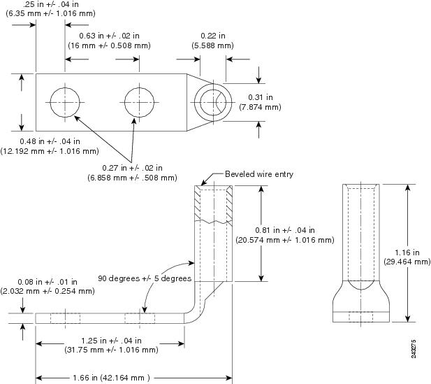
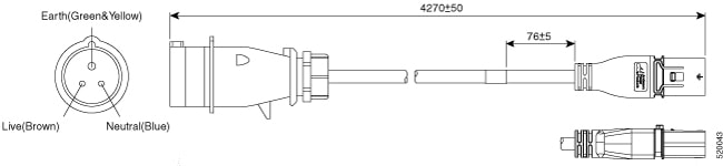
  • PWR-4.4KW-DC-V3: The 4.4KW power supply accepts a nominal input voltage of 48V 60A DC, with an operational tolerance range of -40 to -72 VDC.

    Each 4.4 KW, 60A power module can supply up to 4.4 KW to the power tray when it’s supplied by two feeds (A and B). It can supply up to 2.2 KW with only one feed.

    Figure 1. PWR-4.4KW-DC-V3
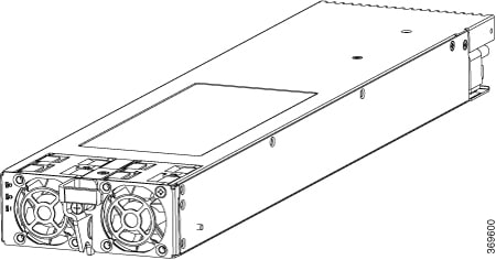
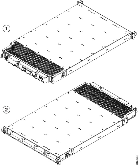
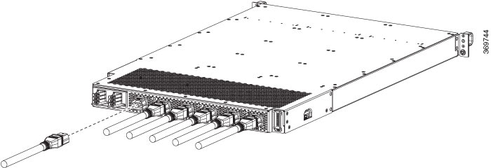
  • PSU4.8KW-DC100: The 4.8KW power supply accepts a nominal input voltage of 48V 100A DC, with an operational tolerance range of -40 to -75 VDC.

    Figure 2. PSU4.8KW-DC100

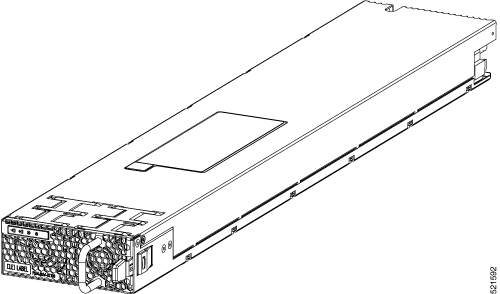
    The PSU4.8KW-DC100 power module can also be configured to accept voltage of 48V 60A. By default, the power module accepts 100A. To change the power mode to 60A, a power mode switch is provided in the power tray. The power mode switch is located in the left-hand side on the power tray.


    Note


    The power mode switch must be in the same position for all power trays installed in the chassis, either 60A or 100A mode.

    When the power mode switch is configured for 100A mode, each power module can supply up to 4.8 KW to the power tray when it’s supplied by two feeds (A and B). In 100A mode, it can supply up to 3.5 KW with only one feed.

    When the power mode switch is configured for 60A mode, each power module can supply up to 4.4 KW to the power tray when it’s supplied by two feeds (A and B). In 60A mode, it can supply up to 2.2 KW with only one feed.
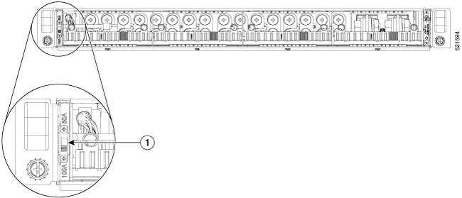
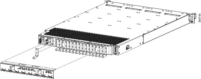
Figure 3. Power Mode Switch on the Power Tray

1

Power mode switch.

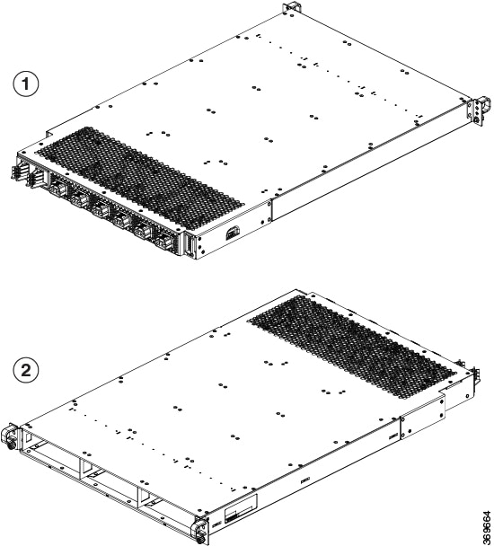
A plug cover is also provided to block the access to the power mode switch as shown in the below figure:
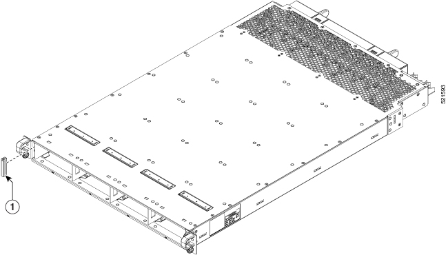
Figure 4. Power Mode Switch Cover

1

Power mode switch cover.

Connect DC Power Supply to Power Source

This section contains the procedures to connect the DC source power cables to a DC-powered router.

For DC power cables, we recommend that you use 60A-rated, high-strand-count copper wire cables (#6 AWG or #4 AWG), or 100A-rated high-strand-count copper wire cables (#2 AWG) . The length of the cables depends on your router location from the source power. DC power cables are not available from Cisco, but they are available from any commercial cable vendor.

You must terminate DC power cables using cable lugs at the power tray end. Ensure that the lugs are right-angle dual-hole and that they fit over to allow quarter inch screws at 0.625-inch (15.88-mm) centers. For #4 AWG cable, use Panduit part number LCD4-14AF-L or equivalent; for #6 AWG, use Panduit part number LCD6-14AF-L or equivalent; for #2 AWG cables, use Panduit part number LCD2-14AF-Q or equivalent.

If you are not using power redundancy or are using n+1 power redundancy, you can connect all the power supplies in the chassis to the same power grid on the rear end of each power tray. If you are using n+n power redundancy, connect one redundant grid to one of the power supply inputs and the other redundant grid to the other power supply input on the back of the power tray as shown for each power supply.

The color coding of source DC power cable leads depends on the color coding of the site DC power source. Ensure that power source cables are connected to the power module with the proper positive (+) and negative (–) polarity:

  • After powering on the router, you should see an LED (for each input) light up green on each power shelf. If LEDs light up red that indicates that the polarity is incorrect.

This figure shows the lug type required for DC input cable connections.

Figure 5. Typical DC Power Cable Lug

Caution


DC power modules contain circuitry to create a fault condition on the power module if the power module detects a reverse polarity condition. No damage should occur from reverse polarity, but ensure to correct a reverse-polarity condition immediately.

Note


The length of the cables depends on the location of your router in relation to the source of DC power. These cables and the cable lugs that are used to attach the cables to the router chassis are not available from Cisco Systems. They are available from any commercial cable vendor.

Caution


To ensure that power remains off while you are performing this procedure, lock-out/tag-out the DC circuit breaker switch in the off (0) position until you are ready to turn it on.

Follow these steps to connect the DC source power cables to a DC power tray:

Procedure


Step 1

Verify that the power tray switch is set to the STANDBY (0) position.

Figure 6. DC Power Tray

1

Rear

2

Front

Step 2

Remove the clear plastic safety covers that fit over the DC power connection terminal studs.

Figure 7. DC Power Connection

Step 3

Connect the DC power cables in the following order.

  1. Positive cables first.

  2. Negative cables last.

Step 4

Repeat Step 3 for the other power modules installed in the tray.

Caution

 
To prevent injury and damage to the equipment, always attach the ground and source DC power cable lugs to power tray terminals in the following order: (1) positive (+) to positive (+), (2) negative (–) to negative (–).

Caution

 
Do not overtighten the nuts that secure the DC power cables to the power tray terminals. Using the 7/16 hex socket and torque wrench the nuts should be tightened to a torque of 45–50 in-lb.

Step 5

Replace the clear plastic safety covers over the connection terminal studs.

Step 6

Turn on the switch of the power shelf to turn on the system.


Connect HVAC/HVDC Power Supply to Power Source

The HVAC/HVDC power supply has 2 redundant input power lines. It can provide a power output of 6.3 kW from each input power line with 2 inputs operating, or provide 4.8 kW (30A) or 3.15 kW (20A) output from either input with one input operating. The HVAC/HVDC power supply provides n+n or n+x line redundancy mode in a single power supply for the Cisco 8800 Series Routers.

The HVAC/HVDC power supply accepts a maximum of 305VAC or 400VDC input power.

If you are not using power redundancy or are using n+1 power redundancy, you can connect all the power supplies in the chassis to the same power grid on the rear end of each power tray. If you are using n+n power redundancy, connect one redundant grid to one of the power supply inputs and the other redundant grid to the other power supply input on the back of the power tray as shown for each power supply.

Before you begin

  • Turn off the power source at its circuit breaker.

  • Check that the power switch is set to the STANDBY (0) position on the power tray.

  • PSU6.3KW-HV: The HVAC or HVDC power sources are rated for 30A maximum input current.

  • PSU6.3KW-20A-HV: The HVAC or HVDC power sources are rated for 20A maximum input current.

Procedure


Step 1

Choose your power supply (HVAC or HVDC) and use a Saf-D-Grid power cable to connect to the power supply tray.

Step 2

For HVAC input, connect a Saf-D-Grid AC power cable to the Saf-D-Grid receptacle.

Figure 8. HV Power Tray

1

Rear

2

Front

Figure 9. HVAC Power Connection

Step 3

For HVDC input, connect a Saf-D-Grid DC cable to a Saf-D-Grid receptacle, otherwise:

  1. Connect the ground terminal ring on the power cable to the ground terminal on the DC power source and secure it in place with a nut tightened to the appropriate torque setting for the terminal post.

  2. Connect the negative terminal ring on the power cable to the negative (-) terminal on the DC power source and secure it in place with a nut tightened to the appropriate torque setting for the terminal post.

  3. Connect the positive terminal ring on the power cable to the negative (+) terminal on the DC power source and secure it in place with a nut tightened to the appropriate torque setting for the terminal post.

Step 4

Verify that the Saf-D-Grid plug is plugged in completely to secure the built-in retaining latch.

Step 5

Turn on the circuit breaker for the HVAC or HVDC power source circuit.

Note

 
If you use both inputs, the IN LED of the power supply is green. If you use only one input, the IN LED is blinking green.

Step 6

Turn on the switch of the power shelf to turn on the system.


What to do next

Use the power-mgmt redundancy-num-pms number command in config mode to convert the power module redundancy from n+1 to n+x, specifying the number of redundant power modules that the you want to configure. The total number of functioning power modules in the system is at least x number more than the number of power modules that are needed to support the power required for all the cards in the system. The range is 0–11; 0 means that no power redundancy is required.

RP/0/RP0/CPU0:ios# config
RP/0/RP0/CPU0:ios(config)# power-mgmt redundancy-num-pms 2
RP/0/RP0/CPU0:ios(config)# commit
Tue Sep 24 09:03:22.889 UTC
Commit complete.

Use the hw-module attention-led location0/PM number command in config mode to enable and use the no form of the command to disable the ID LED on the specified power supply.


RP/0/RP0/CPU0:ios# config
RP/0/RP0/CPU0:ios(config)# hw-module attention-led location 0/PT0-PM0
RP/0/RP0/CPU0:ios(config)# commit
RP/0/RP0/CPU0:ios(config)# end
RP/0/RP0/CPU0:ios# show led location 0/PT0-PM0
================================================================================
Location     Led Name     Mode             Color
================================================================================
0/PT0-PM0
           Attention     OPERATIONAL     BLINKING BLUE
           Fault         OPERATIONAL     OFF
           Input         OPERATIONAL     GREEN
           Output        OPERATIONAL     GREEN 

Power Supply Power Cord Specifications


Note


Always use the Saf-D-Grid connector toward the router.
Table 2. 30A HVAC/HVDC Cables for PSU6.3KW-HV

Locale

Part Number

Cisco Part Number (CPN)

Power Cord Set Rating

Connector Part Number

Power Cord Illustration

AUSTRALIA/NEW ZEALAND

CAB-AC-32A-ANZ

37-101007-01

32A, 250VAC

Saf-D-Grid 3-5958P4 to Hubbell C332P6S Plug

Refer the figure in 30A HVAC/HVDC Cable Illustrations

SWITZERLAND

CAB-AC-32A-CHE

37-101007-01

32A, 250VAC

Saf-D-Grid 3-5958P4 to Hubbell C332P6S Plug

Refer the figure in 30A HVAC/HVDC Cable Illustrations

ITALY

CAB-AC-32A-ITA

37-101007-01

32A, 250VAC

Saf-D-Grid 3-5958P4 to Hubbell C332P6S Plug

Refer the figure in 30A HVAC/HVDC Cable Illustrations

SOUTH AFRICA

CAB-AC-32A-ZAF

37-101007-01

32A, 250VAC

Saf-D-Grid 3-5958P4 to Hubbell C332P6S Plug

Refer the figure in 30A HVAC/HVDC Cable Illustrations

BRAZIL

CAB-AC-32A-BRZ

37-101007-01

32A, 250VAC

Saf-D-Grid 3-5958P4 to Hubbell C332P6S Plug

Refer the figure in 30A HVAC/HVDC Cable Illustrations

ISRAEL

CAB-AC-32A-ISR

37-101007-01

32A, 250VAC

Saf-D-Grid 3-5958P4 to Hubbell C332P6S Plug

Refer the figure in 30A HVAC/HVDC Cable Illustrations

ARGENTINA

CAB-AC-32A-ARG

37-101007-01

32A, 250VAC

Saf-D-Grid 3-5958P4 to Hubbell C332P6S Plug

Refer the figure in 30A HVAC/HVDC Cable Illustrations

INDIA

CAB-AC-32A-IND

37-101007-01

32A, 250VAC

Saf-D-Grid 3-5958P4 to Hubbell C332P6S Plug

Refer the figure in 30A HVAC/HVDC Cable Illustrations

NORTH AMERICA

CAB-AC-30A-US1

37-101008-01

30A, 250VAC

Saf-D-Grid 3-5958P4 to VOLEX 174606

Refer the figure in 30A HVAC/HVDC Cable Illustrations

NORTH AMERICA

CAB-AC-30A-US2

37-101009-01

30A, 250VAC

Saf-D-Grid 3-5958P4 to VOLEX 174606

Refer the figure in 30A HVAC/HVDC Cable Illustrations

NORTH AMERICA

CAB-DC-30A-US1

37-101014-01

30A, 400VDC

Saf-D-Grid 3-5958P4 to Saf-D-Grid 3-5958P4

Refer the figure in 30A HVAC/HVDC Cable Illustrations

NORTH AMERICA

CAB-DC-30A-US2

37-101016-01

30A, 400VDC

Saf-D-Grid 3-5958P4 to Saf-D-Grid 3-5958P4

Refer the figure in 30A HVAC/HVDC Cable Illustrations

NORTH AMERICA

CAB-AC-30A-US3

37-101013-01

30A, 277VAC

Saf-D-Grid 3-5958P4 to HBL2631

Refer the figure in 30A HVAC/HVDC Cable Illustrations

NORTH AMERICA

CAB-AC-30A-US4

37-101018-01

30A, 300VAC

Saf-D-Grid 3-5958P4 to Saf-D-Grid 3-6074P30

Refer the figure in 30A HVAC/HVDC Cable Illustrations

IEC/EU

CAB-AC-32A-EU

37-101019-01

32A, 300VAC

Saf-D-Grid 3-5958P4 to Saf-D-Grid 3-6074P30

Refer the figure in 30A HVAC/HVDC Cable Illustrations

IEC/EU

CAB-DC-32A-EU1

37-101015-01

32A, 400VDC

Saf-D-Grid 3-5958P4 to Saf-D-Grid 3-5958P4

Refer the figure in 30A HVAC/HVDC Cable Illustrations

IEC/EU

CAB-DC-32A-EU2

37-101017-01

32A, 400VDC

Saf-D-Grid 3-5958P4 to Saf-D-Grid 3-5958P4

Refer the figure in 30A HVAC/HVDC Cable Illustrations

CHINA

CAB-AC-32A-CHN

37-101010-01

32A, 250VAC

-

Refer the figure in 30A HVAC/HVDC Cable Illustrations

KOREA

CAB-AC-32A-KOR

37-101012-01

32A, 250VAC

-

Refer the figure in 30A HVAC/HVDC Cable Illustrations

30A HVAC/HVDC Cable Illustrations

Figure 10. CAB-AC-32A-ANZ, CAB-AC-32A-CHE, CAB-AC-32A-ITA, CAB-AC-32A-BRZ, CAB-AC-32A-ZAF, CAB-AC-32A-ISR, CAB-AC-32A-IND, CAB-AC-32A-ARG Power Cord and Plugs for Standard AC Power Supply
Figure 11. CAB-AC-30A-US1 Power Cord and Plugs for Standard AC Power Supply
Figure 12. CAB-AC-30A-US2 Power Cord and Plugs for Standard AC Power Supply
Figure 13. CAB-DC-30A-US1 Power Cord and Plugs for HVDC Power Supply
Figure 14. CAB-DC-30A-US2 Power Cord and Plugs for HVDC Power Supply
Figure 15. CAB-AC-30A-US3 Power Cord and Plugs for Standard AC Power Supply
Figure 16. CAB-AC-30A-US4 Power Cord and Plugs for Standard AC Power Supply
Figure 17. CAB-AC-32A-EU Power Cord and Plugs for Standard AC Power Supply
Figure 18. CAB-DC-32A-EU1 Power Cord and Plugs for HVDC Power Supply
Figure 19. CAB-DC-32A-EU2 Power Cord and Plugs for HVDC Power Supply
Figure 20. CAB-AC-32A-CHN Power Cord and Plugs for Standard AC Power Supply
Figure 21. CAB-AC-32A-KOR Power Cord and Plugs for Standard AC Power Supply
Table 3. 20A HVAC/HVDC Cables for PSU6.3KW-20A-HV
Locale Part Number Cisco Part Number (CPN) Length Power Cord Rating Connectors

Power Cord Illustration

Argentina CAB-AC-16A-SG-AR 37-1649-01 14 ft (4.26 m) 16A, 250 VAC

Refer the figure in 20A HVAC/HVDC Cables for PSU6.3KW-20A-HV

Australia CAB-AC-16A-SG-AZ 37-1661-01 14 ft (4.26 m) 16A, 250 VAC

Refer the figure in 20A HVAC/HVDC Cables for PSU6.3KW-20A-HV

Brazil CAB-AC-16A-SG-BR 37-1650-01 14 ft (4.26 m) 16A, 250 VAC

Refer the figure in 20A HVAC/HVDC Cables for PSU6.3KW-20A-HV

China CAB-AC-16A-SG-CH 37-1655-01 14 ft (4.26 m) 16A, 250 VAC

Refer the figure in 20A HVAC/HVDC Cables for PSU6.3KW-20A-HV

China CAB-AC-16A-CN 37-1655-01 14 ft (4.26 m) 16A, 250 VAC

Refer the figure in 20A HVAC/HVDC Cables for PSU6.3KW-20A-HV

Europe CAB-AC-16A-SG-EU 37-1660-01 14 ft (4.26 m) 16A, 250 VAC

Refer the figure in 20A HVAC/HVDC Cables for PSU6.3KW-20A-HV

India CAB-AC-16A-SG-IND 37-1863-01 14 ft (4.26 m) 16A, 250 VAC

Refer the figure in 20A HVAC/HVDC Cables for PSU6.3KW-20A-HV

International/UK CAB-AC-16A-SG-IN 37-1659-01 14 ft (4.26 m) 16A, 250 VAC

Refer the figure in 20A HVAC/HVDC Cables for PSU6.3KW-20A-HV

Israel CAB-AC-16A-SG-IS 37-1658-01 14 ft (4.26 m) 16A, 250 VAC

Refer the figure in 20A HVAC/HVDC Cables for PSU6.3KW-20A-HV

Italy CAB-AC-16A-SG-IT 37-1651-01 14 ft (4.26 m) 16A, 250 VAC

Refer the figure in 20A HVAC/HVDC Cables for PSU6.3KW-20A-HV

Japan CAB-AC-16A-SG-JPN 37-1656-01 14 ft (4.26 m) 16A, 250 VAC

Refer the figure in 20A HVAC/HVDC Cables for PSU6.3KW-20A-HV

South Africa CAB-AC-16A-SG-SA 37-1647-01 14 ft (4.26 m) 16A, 250 VAC

Refer the figure in 20A HVAC/HVDC Cables for PSU6.3KW-20A-HV

Switzerland CAB-AC-16A-SG-SW 37-1654-01 14 ft (4.26 m) 16A, 250 VAC

Refer the figure in 20A HVAC/HVDC Cables for PSU6.3KW-20A-HV

South Korea CAB-AC-16A-SG-SK 37-1646-01 14 ft (4.26 m) 16A, 250 VAC

Refer the figure in 20A HVAC/HVDC Cables for PSU6.3KW-20A-HV

UK CAB-AC-16A-SG-UK 37-1864-01 14 ft (4.26 m) 16A, 250 VAC

Refer the figure in 20A HVAC/HVDC Cables for PSU6.3KW-20A-HV

North America (locking) 200-240 VAC operation CAB-AC-20A-SG-US3 37-1656-01 14 ft (4.26 m) 20A, 250 VAC Saf-D-Grid to L6-20

Refer the figure in 20A HVAC/HVDC Cables for PSU6.3KW-20A-HV

North America 277 VAC operation CAB-AC-20A-SG-US4 37-1645-01 14 ft (4.26 m) 20A, 277 VAC Saf-D-Grid to L7-20

Refer the figure in 20A HVAC/HVDC Cables for PSU6.3KW-20A-HV

North America Cabinet Jumper Power Distribution unit (PDU) CAB-AC-20A-SG-C20 37-1653-01 14 ft (4.26 m) 20A, 250 VAC Saf-D-Grid to C20

Refer the figure in 20A HVAC/HVDC Cables for PSU6.3KW-20A-HV

North America, Ring Terminal source plug CAB-HV-25A-SG-US2 37-1641-01 14 ft (4.26 m) 20A, 300 VAC/500 VDC Saf-D-Grid to 3 ring terminal

Refer the figure in 20A HVAC/HVDC Cables for PSU6.3KW-20A-HV

International IEC/EU, Ring Terminal source plug CAB-HV-25A-SG-IN2 37-1640-01 14 ft (4.26 m) 20A, 300 VAC/500 VDC Saf-D-Grid to 3 ring terminal

Refer the figure in 20A HVAC/HVDC Cables for PSU6.3KW-20A-HV

US, IEC/EU, CANADA, MEXICO, BRAZIL, NETHERLANDS, IRELAND, FRANCE, UK, GERMANY, SWITZERLAND, NORWAY, SPAIN, ITALY, SINGAPORE, CHINA CAB-AC-20A-NA 37-2126-01 6.6 ft (2m) 20A, 250VAC Saf-D-Grid 3-5958P2 to IEC 60320 C20

Refer the figure in 20A HVAC/HVDC Cables for PSU6.3KW-20A-HV

20A HVAC/HVDC Cable Illustrations
Figure 22. CAB-AC-16A-SG-AR Power Cord
Figure 23. CAB-AC-16A-SG-AZ Power Cord
Figure 24. CAB-AC-16A-SG-BR Power Cord
Figure 25. CAB-AC-16A-SG-CH Power Cord
Figure 26. CAB-AC-16A-SG-EU Power Cord
Figure 27. CAB-AC-16A-SG-IND Power Cord
Figure 28. CAB-AC-16A-SG-IN Power Cord
Figure 29. CAB-AC-16A-SG-IS Power Cord
Figure 30. CAB-AC-16A-SG-IT Power Cord
Figure 31. CAB-AC-16A-SG-JPN Power Cord
Figure 32. CAB-AC-16A-SG-SA Power Cord
Figure 33. CAB-AC-16A-SG-SW Power Cord
Figure 34. CAB-AC-16A-SG-UK Power Cord
Figure 35. CAB-AC-20A-SG-US Power Cord
Figure 36. CAB-AC-20A-SG-US1 Power Cord
Figure 37. CAB-AC-20A-SG-US2 Power Cord
Figure 38. CAB-AC-20A-SG-US3 Power Cord
Figure 39. CAB-AC-20A-SG-US4 Power Cord
Figure 40. CAB-AC-20A-SG-C20 Power Cord
Figure 41. CAB-HV-25A-SG-US2 Power Cord
Figure 42. CAB-HV-25A-SG-IN2 Power Cord
Figure 43. CAB-HV-25A-SG-IN3 Power Cord
Figure 44. CAB-AC-20A-NA Power Cord