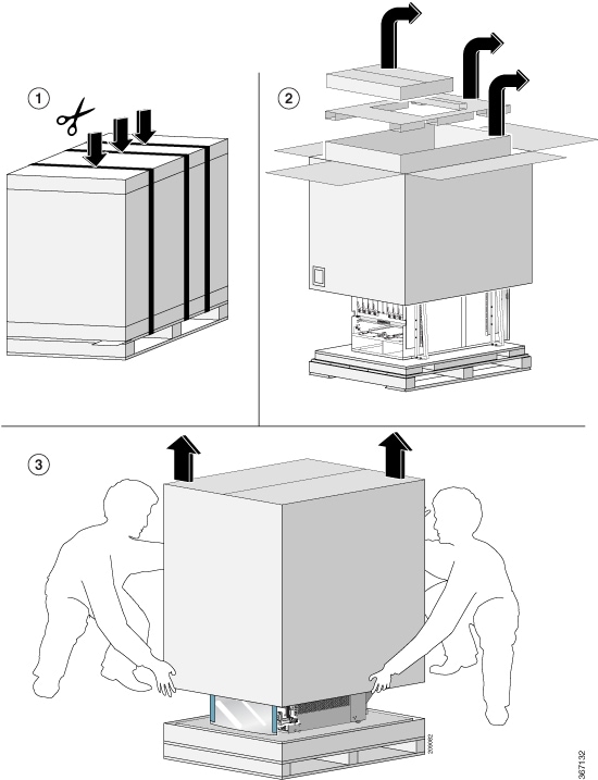
Unpack the Chassis
 Tip |
Be sure to save the packaging in case you need to return any of the components products. |
Ensure that there is sufficient room around the chassis pallet for unpacking. For information about the chassis dimensions and clearance requirements see, Clearance Requirements.
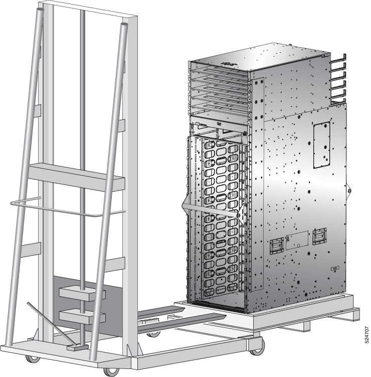
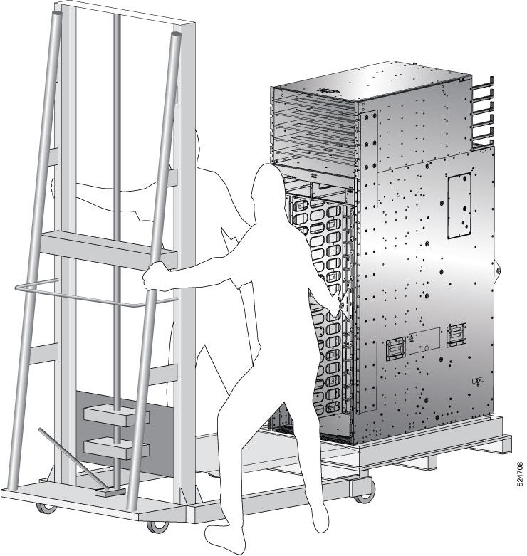
Carefully move the pallet containing the chassis to the staging area where you plan on unpacking it.
 Note |
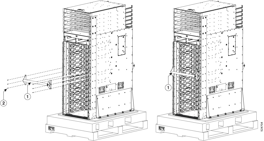
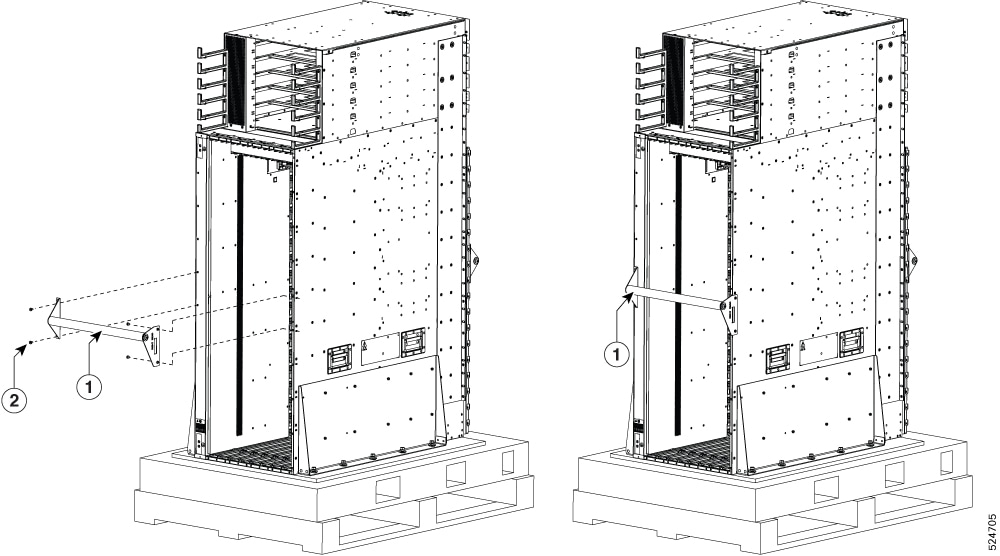
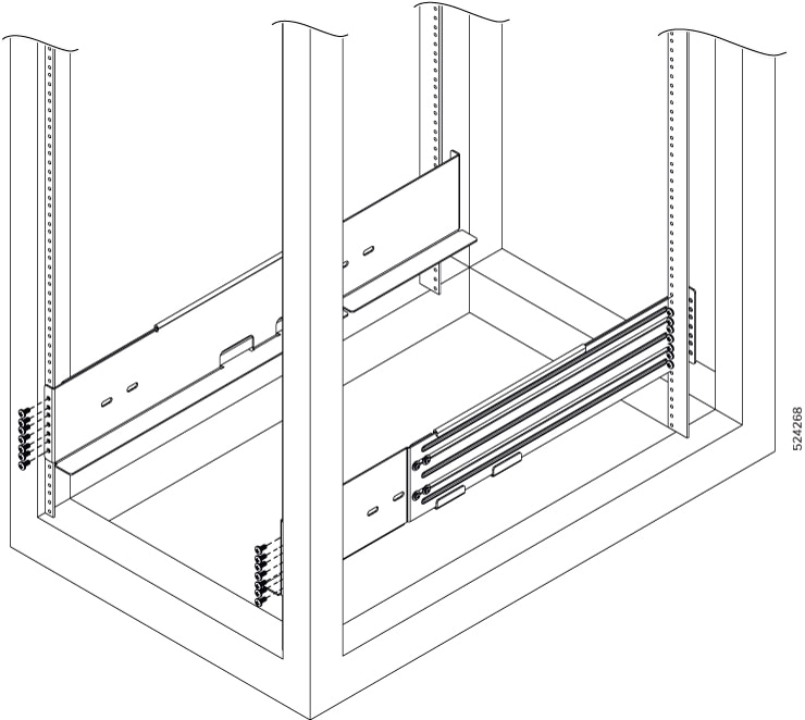
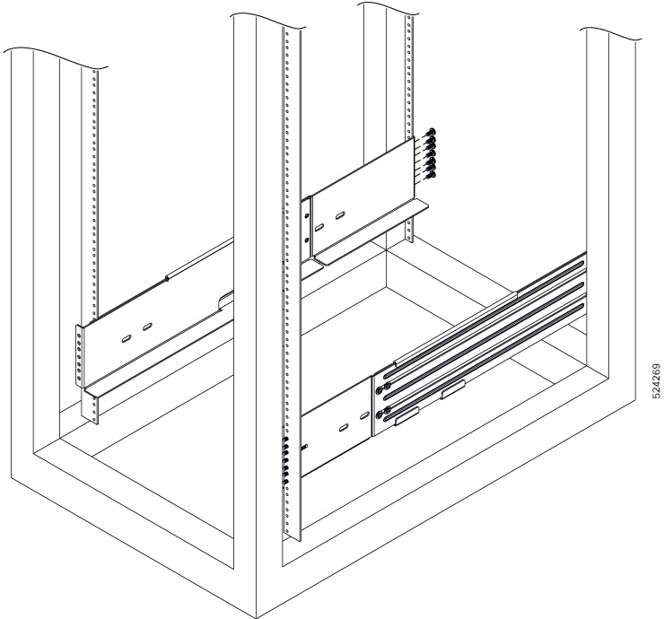
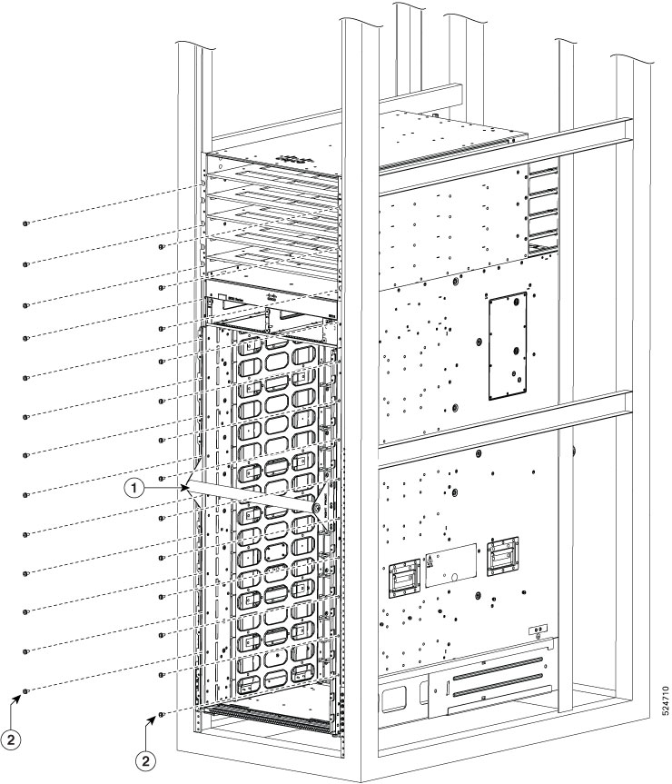
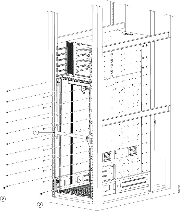
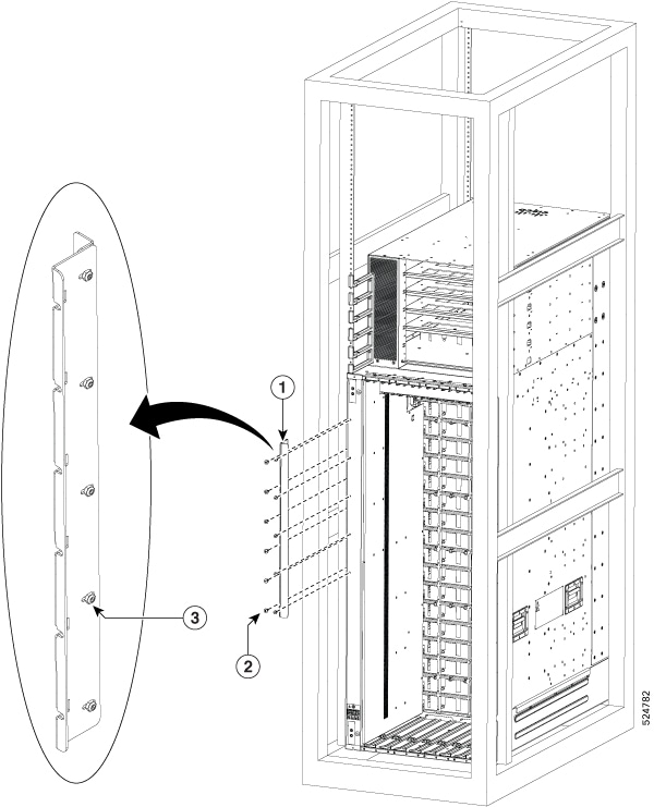
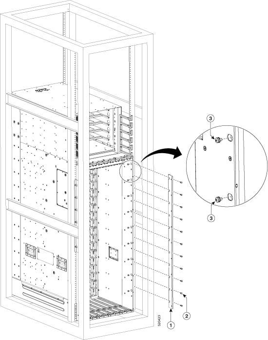
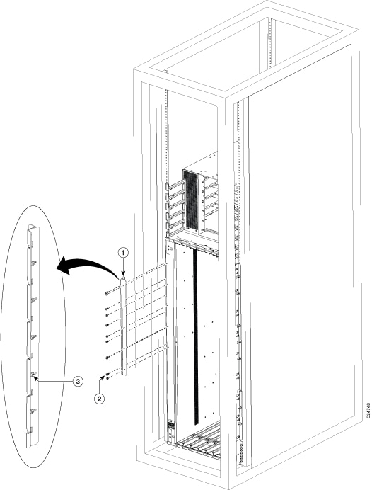
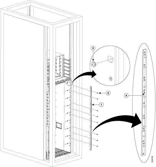
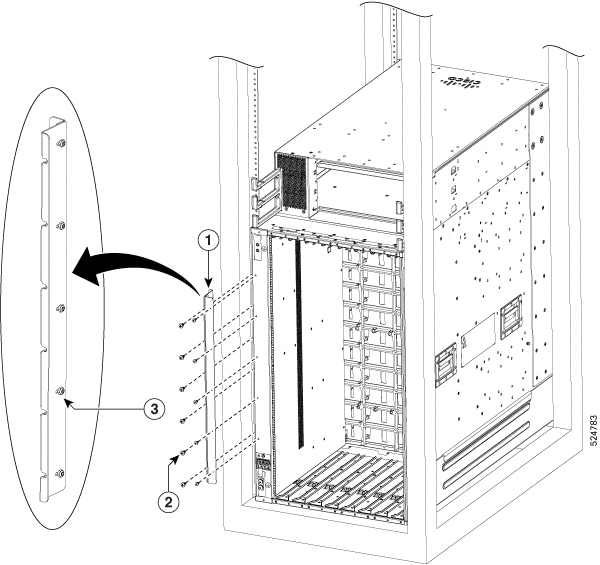
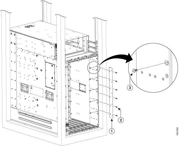
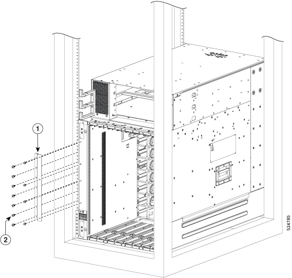
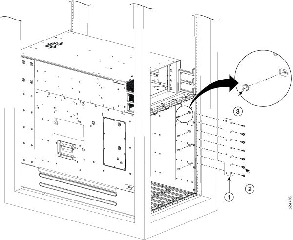
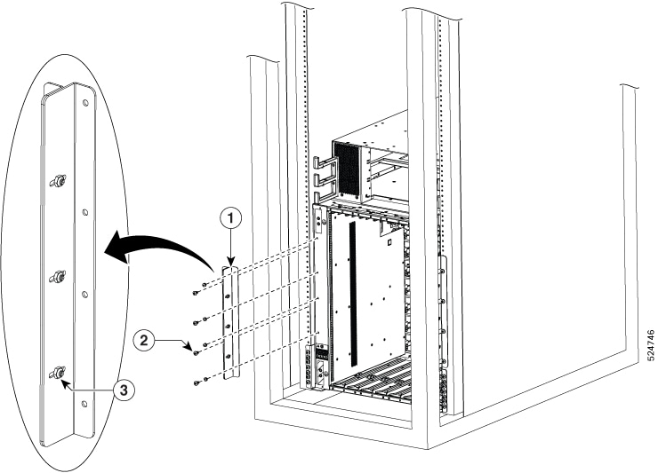
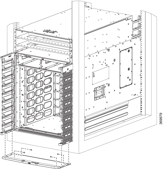
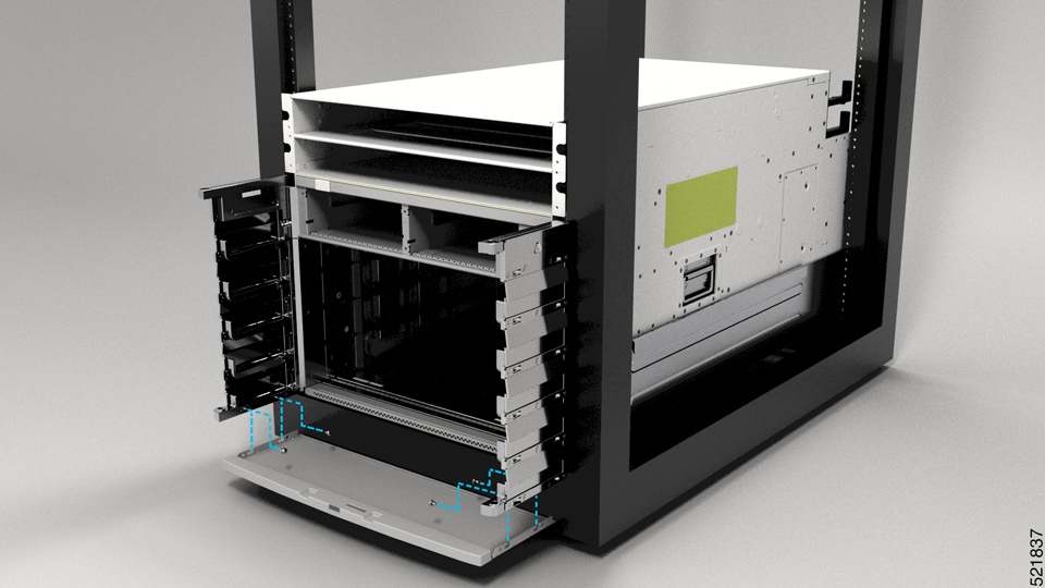
Unpack the Cisco 8818 chassis, then immediately install the pull-bars. Do not remove the shipping brackets or move the chassis from the pallet until this is done. See (Only Cisco 8818) Install the Pull bars on the Chassis. |
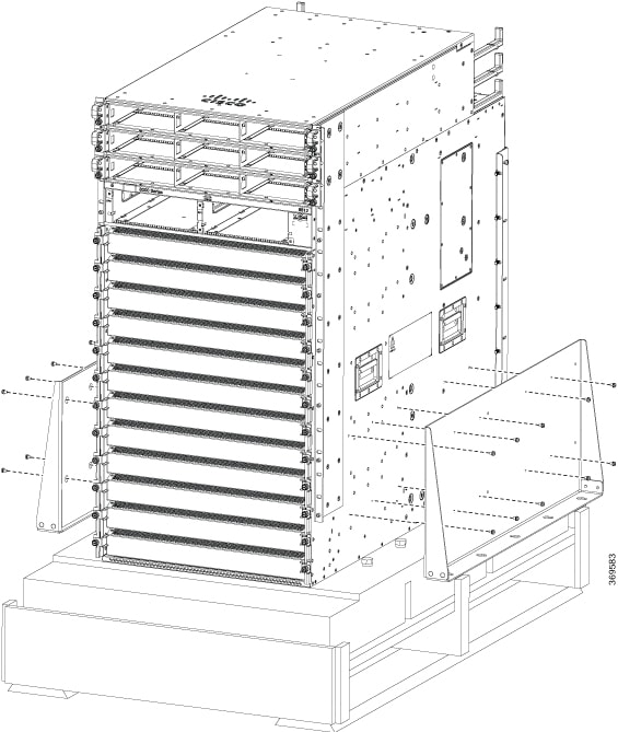
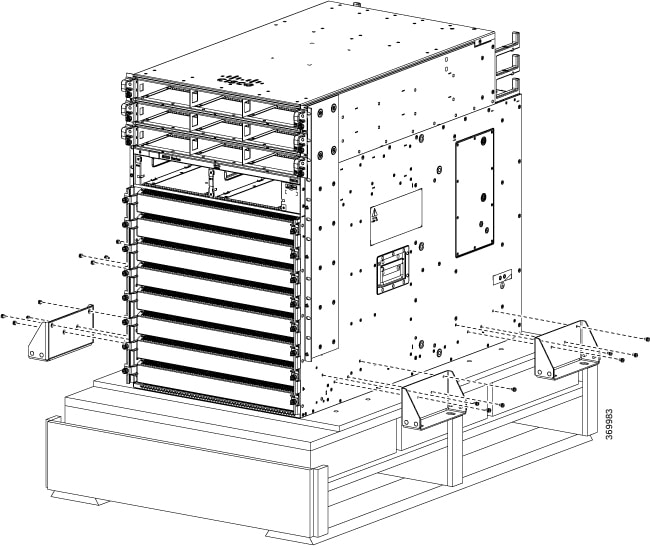
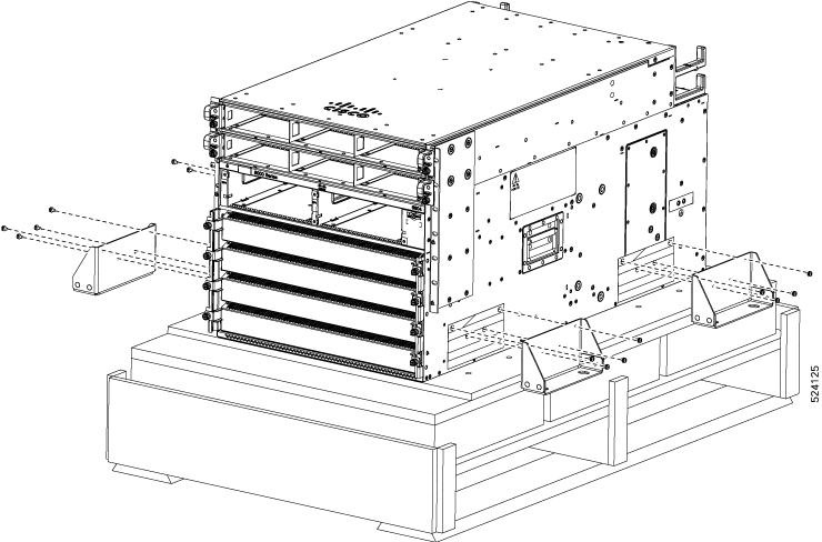
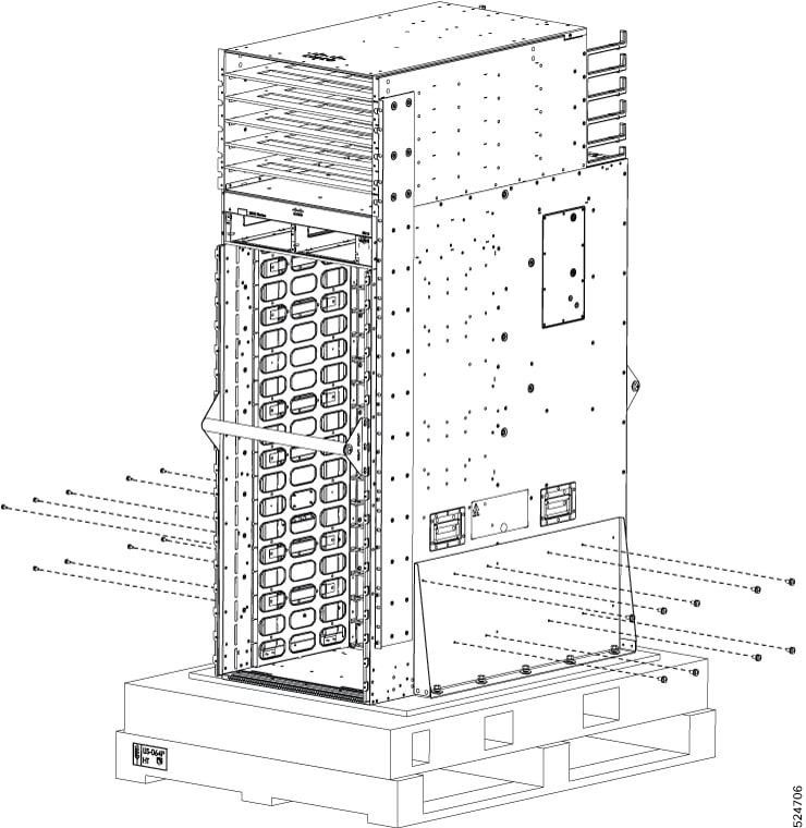
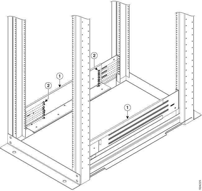
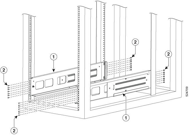
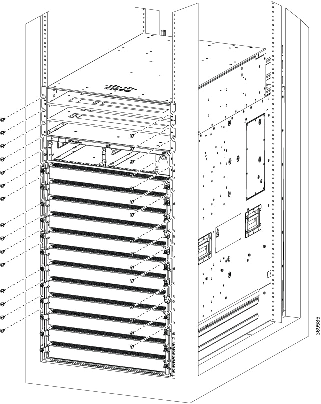
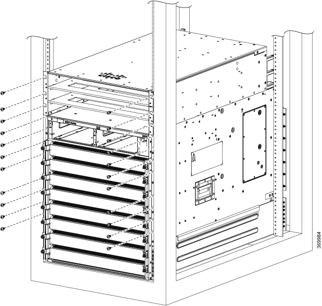
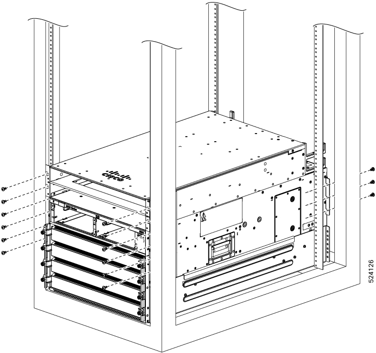
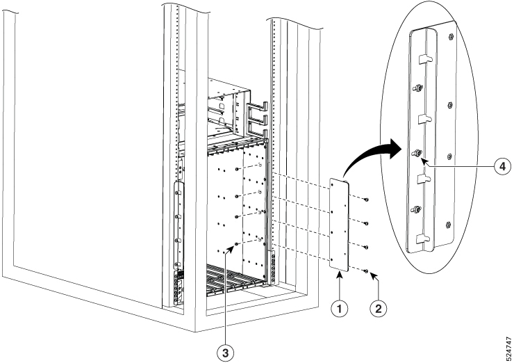
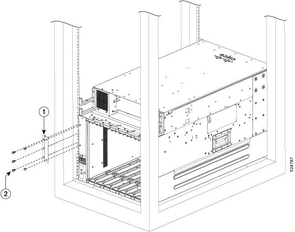
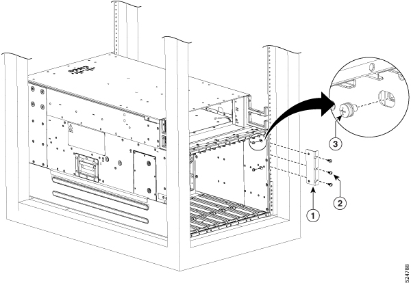
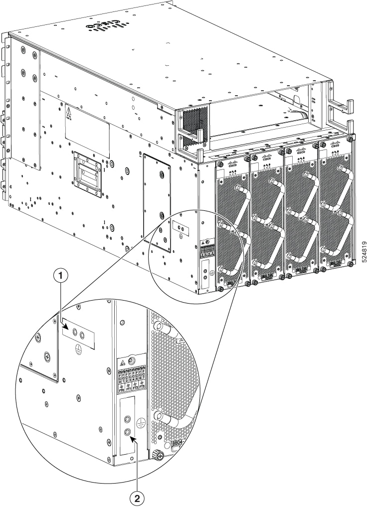
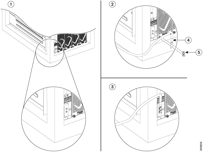
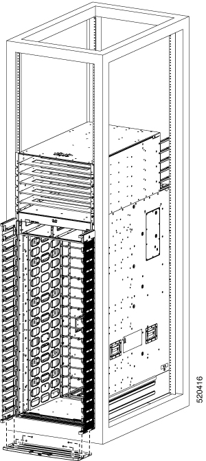
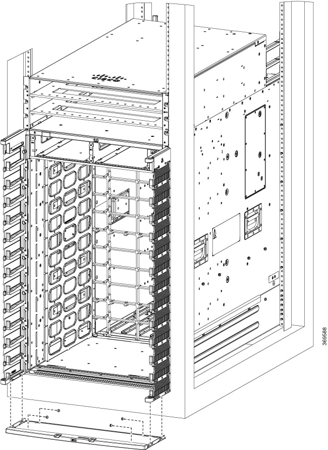
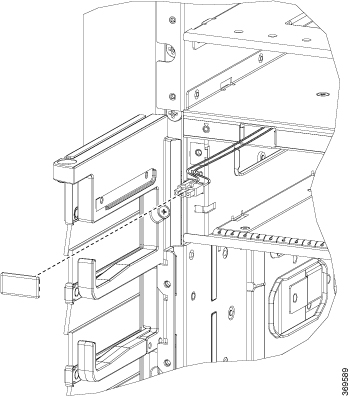
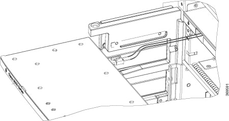
Remove the shipping brackets:
-
20 x M4 screws from the 8812 chassis
-
16 x M4 screws from the 8808 chassis
-
16 x M4 screws from the 8804 chassis
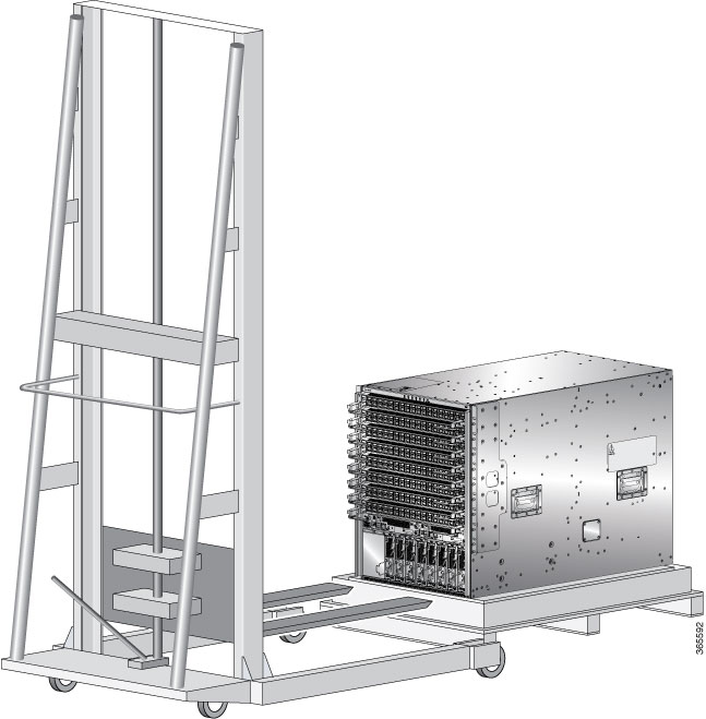
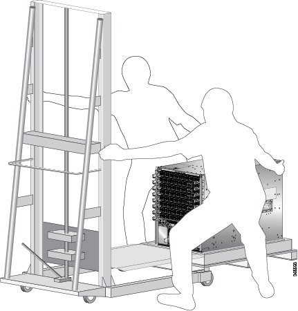
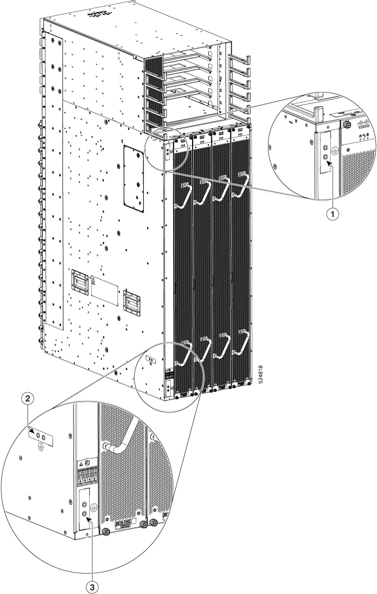
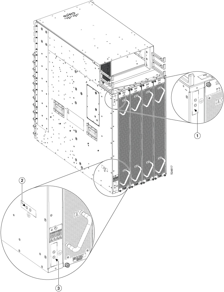
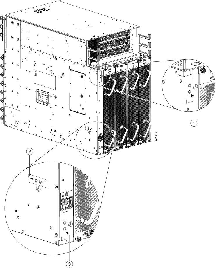
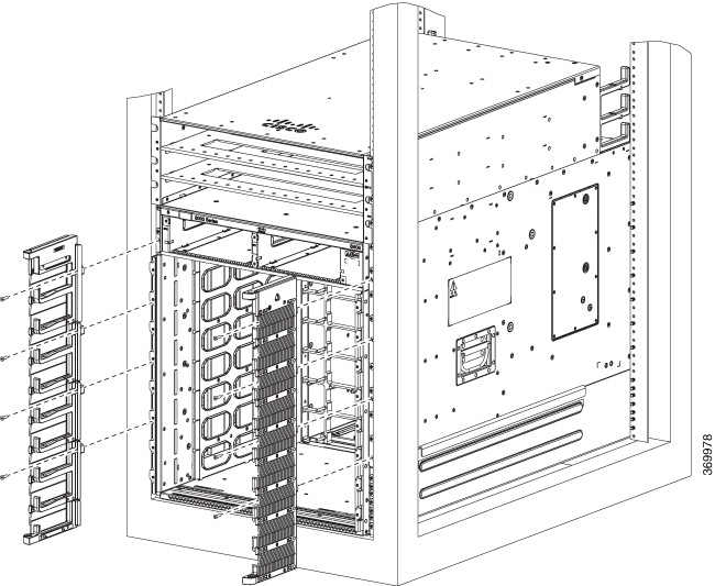
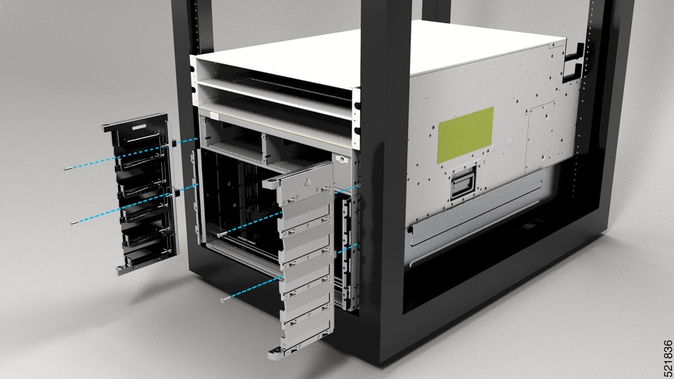
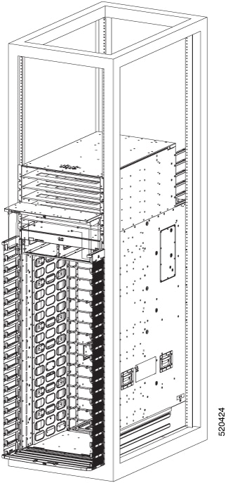
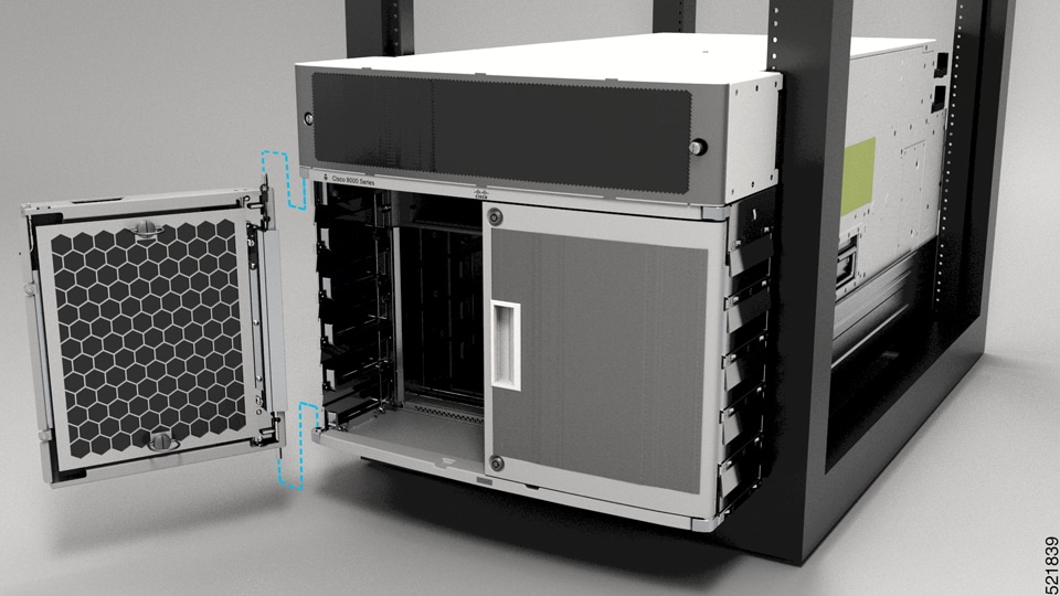
To make the chassis weigh less for moving, remove the following module and place them where their connectors will not be damaged:
-
Fan trays
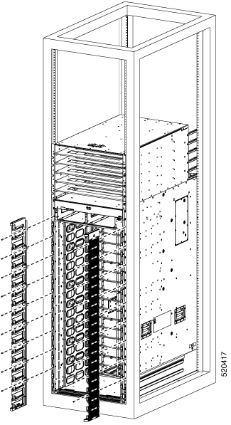
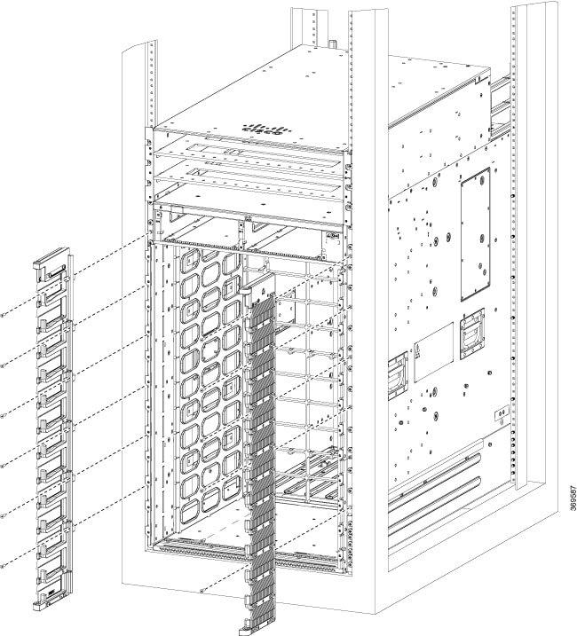
Leave the chassis on the pallet until you are ready to move and install the chassis in a rack.
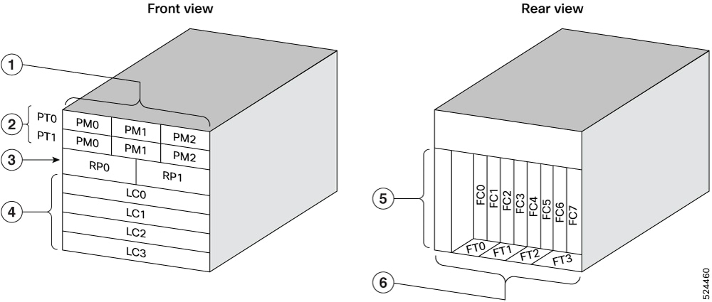
|
1 |
Power Modules |
4 |
Line Cards |
|
2 |
Power Trays |
5 |
Fabric Cards |
|
3 |
Route Processors |
6 |
Fan Trays |

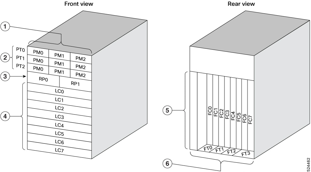
|
1 |
Power Modules |
4 |
Line Cards |
|
2 |
Power Trays |
5 |
Fabric Cards |
|
3 |
Route Processors |
6 |
Fan Trays |
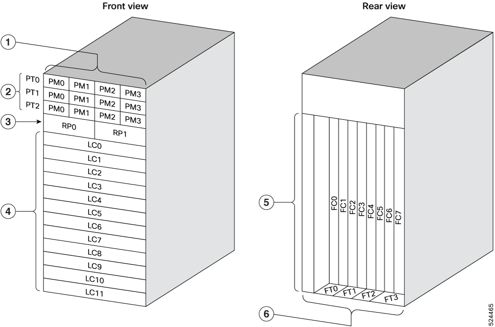
|
1 |
Power Modules |
4 |
Line Cards |
|
2 |
Power Trays |
5 |
Fabric Cards |
|
3 |
Route Processors |
6 |
Fan Trays |

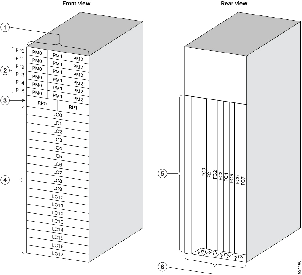
|
1 |
Power Modules |
4 |
Line Cards |
|
2 |
Power Trays |
5 |
Fabric Cards |
|
3 |
Route Processors |
6 |
Fan Trays |

|
1 |
Power Modules |
4 |
Line Cards |
|
2 |
Power Trays |
5 |
Fabric Cards |
|
3 |
Route Processors |
6 |
Fan Trays |
|
1 |
Power Modules |
4 |
Line Cards |
|
2 |
Power Trays |
5 |
Fabric Cards |
|
3 |
Route Processors |
6 |
Fan Trays |
|
1 |
Power Modules |
4 |
Line Cards |
|
2 |
Power Trays |
5 |
Fabric Cards |
|
3 |
Route Processors |
6 |
Fan Trays |

|
1 |
Power Modules |
4 |
Line Cards |
|
2 |
Power Trays |
5 |
Fabric Cards |
|
3 |
Route Processors |
6 |
Fan Trays |

 Feedback