BGP
Border Gateway Protocol (BGP) is an inter-domain routing protocol that provides loop-free routing between organizations or autonomous systems.
Cisco NX-OS supports BGP version 4. This version includes multiprotocol extensions that allow BGP to carry routing information for IP multicast routes and multiple Layer 3 protocol address families.
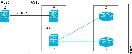
BGP uses TCP as a reliable transport protocol to create TCP sessions with other BGP-enabled devices called BGP peers. When connecting to an external organization, a router creates external BGP (eBGP) peering sessions. When connecting to a BGP peer within the same organization to exchange routing information, a router creates internal BGP (iBGP) peering sessions.
BGP uses a path-vector routing algorithm to exchange routing information among BGP-enabled networking devices or BGP speakers. Based on this information, each BGP speaker determines a path to reach a destination while detecting and avoiding paths with routing loops. The routing information includes the prefix for a destination, the path of autonomous systems to the destination, and other path attributes.
By default, BGP selects a single path as the best path to a destination host or network. Each path includes well-known mandatory attributes, well-known discretionary attributes, and optional transitive attributes for BGP best-path analysis. You can influence BGP path selection by altering some of these attributes by configuring BGP policies. For more information, see Route Policies and Resetting BGP Sessions. BGP also supports load balancing or equal-cost multipath (ECMP). For more information, see Load Sharing and Multipath.
Beginning with Cisco NX-OS Release 10.5(1)F, Configuring Basic BGP and Configuring Advanced BGP chapters are merged to create Configuring BGP chapter.
BGP autonomous systems
An autonomous system (AS) is a network controlled by a single administration entity. An autonomous system forms a routing domain with one or more interior gateway protocols (IGPs) and a consistent set of routing policies.
BGP supports 16-bit and 32-bit autonomous system numbers. For more information, see the Autonomous Systems section.
Separate BGP autonomous systems dynamically exchange routing information through external BGP (eBGP) peering sessions. BGP speakers within the same autonomous system can exchange routing information through internal BGP (iBGP) peering sessions.
4-Byte AS number support
BGP supports 2-byte autonomous system (AS) numbers in plain-text notation or as.dot notation and 4-byte AS numbers in plain-text notation.
When BGP is configured with a 4-byte AS number, the route-target auto VXLAN command cannot be used because the AS number along with the VNI (which is already a 3-byte value) is used to generate the route target. For more information, see the Cisco Nexus 9000 Series NX-OS VXLAN Configuration Guide.
Administrative distance
An administrative distance is a rating of the trustworthiness of a routing information source. By default, BGP uses the administrative distances shown in the table.
|
Distance |
Default Value |
Function |
|---|---|---|
|
External |
20 |
Applied to routes learned from eBGP. |
|
Internal |
200 |
Applied to routes learned from iBGP. |
|
Local |
220 |
Applied to routes originated by the router. |
 Note |
The administrative distance does not influence the BGP path selection algorithm, but it does influence whether BGP-learned routes are installed in the IP routing table. |
For more information, see the Administrative Distance section.
BGP peers
A BGP peer is a BGP speaker that has an active TCP connection to another BGP speaker.
A BGP speaker does not discover another BGP speaker automatically. You must configure the relationships between BGP speakers.
BGP sessions
BGP sessions are TCP connections established between Border Gateway Protocol (BGP) peers that enable the exchange of routing information. BGP uses TCP port 179 to create these sessions, which serve as the communication channel for exchanging routing updates and maintaining network topology awareness.
After this initial exchange, the BGP peers send only incremental updates when a topology change occurs in the network or when a routing policy change occurs. In the periods of inactivity between these updates, peers exchange special messages called keepalives. The hold time is the maximum time limit that can elapse between receiving consecutive BGP update or keepalive messages.
Cisco NX-OS supports these peer configuration options:
-
Individual IPv4 or IPv6 address: BGP establishes a session with the BGP speaker that matches the remote address and AS number.
-
IPv4 or IPv6 prefix peers for a single AS number: BGP establishes sessions with BGP speakers that match the prefix and the AS number.
-
Dynamic AS number prefix peers: BGP establishes sessions with BGP speakers that match the prefix and an AS number from a list of configured AS numbers.
Dynamic AS numbers for prefix peers and interface peers
Dynamic AS numbers are a feature in Cisco NX-OS BGP configurations that allow you to specify a range or list of Autonomous System (AS) numbers for establishing BGP sessions with prefix peers or interface peers. This means BGP will accept sessions only from peers whose AS numbers match those in the configured list or range.
Cisco NX-OS accepts a range or list of AS numbers to establish BGP sessions. For example, if you configure BGP to use IPv4 prefix 192.0.2.0/8 and AS numbers 33, 66, and 99, BGP establishes a session with 192.0.2.1 with AS number 66 but rejects a session from 192.0.2.2 with AS number 50.
Beginning with Cisco NX-OS Release 9.3(6), support for dynamic AS numbers is extended to interface peers in addition to prefix peers. See Configure BGP Interface Peering via IPv6 Link-Local for IPv4 and IPv6 Address Families.
Cisco NX-OS does not associate prefix peers with dynamic AS numbers as either interior BGP (iBGP) or external BGP (eBGP) sessions until after the session is established. See Configuring Advanced BGP for more information on iBGP and eBGP.
Note |
The dynamic AS number prefix peer configuration overrides the individual AS number configuration that is inherited from a BGP template. For more information, see Configuring Advanced BGP. |
BGP router identifier
To establish BGP sessions between peers, BGP must have a router ID, which is sent to BGP peers in the OPEN message when a BGP session is established. The BGP router ID is a 32-bit value that is often represented by an IPv4 address. You can configure the router ID. By default, Cisco NX-OS sets the router ID to the IPv4 address of a loopback interface on the router. If no loopback interface is configured on the router, the software chooses the highest IPv4 address configured to a physical interface on the router to represent the BGP router ID. The BGP router ID must be unique to the BGP peers in a network.
If BGP does not have a router ID, it cannot establish any peering sessions with BGP peers.
Each routing process has an associated router ID. You can configure the router ID to any interface in the system. If you do not configure the router ID, Cisco NX-OS selects the router ID based on the following criteria:
-
Cisco NX-OS prefers loopback0 over any other interface. If loopback0 does not exist, then Cisco NX-OS prefers the first loopback interface over any other interface type.
-
If you have not configured a loopback interface, Cisco NX-OS uses the first interface in the configuration file as the router ID. If you configure any loopback interface after Cisco NX-OS selects the router ID, the loopback interface becomes the router ID. If the loopback interface is not loopback0 and you configure loopback0 with an IP address, the router ID changes to the IP address of loopback0.
-
If the interface that the router ID is based on changes, that new IP address becomes the router ID. If any other interface changes its IP address, there is no router ID change.
BGP path selection
BGP best-path algorithm is a process used by Cisco NX-OS to select the optimal path for routing a given network prefix when multiple valid paths are available. For information on configuring additional BGP paths, see Configuring Advance BGP.
The best-path algorithm runs each time that a path is added or withdrawn for a given network. The best-path algorithm also runs if you change the BGP configuration. BGP selects the best path from the set of valid paths available for a given network.
Cisco NX-OS implements the BGP best-path algorithm in these steps:
-
Compares two paths to determine which is better. See the Step 1 Comparing Pairs of Paths section).
-
Explores all paths and determines in which order to compare the paths to select the overall best path. See the Step 2 Determining the Order of Comparisons section.
-
Determines whether the old and new best paths differ enough so that the new best path should be used. See the Step 3 Determining the Best-Path Change Suppressionsection.
Note |
The order of comparison determined in Part 2 is important. Consider the case where you have three paths, A, B, and C. When Cisco NX-OS compares A and B, it chooses A. When Cisco NX-OS compares B and C, it chooses B. But when Cisco NX-OS compares A and C, it might not choose A because some BGP metrics apply only among paths from the same neighboring autonomous system and not among all paths. |
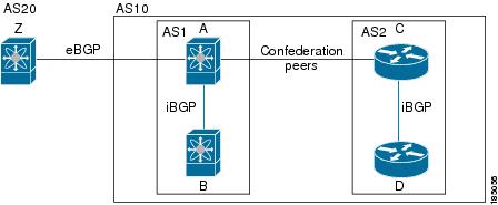
The path selection uses the BGP AS-path attribute. The AS-path attribute includes the list of autonomous system numbers (AS numbers) traversed in the advertised path. If you subdivide your BGP autonomous system into a collection or confederation of autonomous systems, the AS-path contains confederation segments that list these locally defined autonomous systems.
Note |
VXLAN deployments use a BGP path selection process that differs from the normal selection of local over remote paths. For the EVPN address family, BGP compares the sequence number in the MAC Mobility attribute (if present) and selects the path with the higher sequence number. If both paths being compared have the attribute and the sequence numbers are the same, BGP prefers the path that is learned from the remote peer over a locally originated path. For more information, see the Cisco Nexus 9000 Series NX-OS VXLAN Configuration Guide. |
BGP path selection - comparing pairs of paths
This first step in the BGP best-path algorithm compares two paths to determine which path is better. These following sequences describe the basic steps that Cisco NX-OS uses to compare two paths to determine the better path:
-
Cisco NX-OS chooses a valid path for comparison. For example, a path that has an unreachable next hop is not valid.
-
Cisco NX-OS chooses the path with the highest weight.
-
Cisco NX-OS chooses the path with the highest local preference.
-
If one of the paths is locally originated, Cisco NX-OS chooses that path.
-
Cisco NX-OS chooses the path with the shorter AS path.
Note
When calculating the length of the AS-path, Cisco NX-OS ignores confederation segments and counts AS sets as 1. See the AS confederations section for more information.
-
Cisco NX-OS chooses the path with the lower origin. Interior Gateway Protocol (IGP) is considered lower than EGP.
-
Cisco NX-OS chooses the path with the lower multiexit discriminator (MED).
You can configure Cisco NX-OS to always perform the best-path algorithm MED comparison, regardless of the peer autonomous system in the paths. See the Tune the best-path algorithm section for more information. Otherwise, Cisco NX-OS performs a MED comparison that depends on the AS-path attributes of the two paths being compared.
You can configure Cisco NX-OS to always perform the best-path algorithm MED comparison, regardless of the peer autonomous system in the paths. Otherwise, Cisco NX-OS performs a MED comparison that depends on the AS-path attributes of the two paths being compared these ways:
-
If a path has no AS-path or the AS-path starts with an AS_SET, the path is internal and Cisco NX-OS compares the MED to other internal paths.
-
If the AS-path starts with an AS_SEQUENCE, the peer autonomous system is the first AS number in the sequence and Cisco NX-OS compares the MED to other paths that have the same peer autonomous system.
-
If the AS-path contains only confederation segments or starts with confederation segments followed by an AS_SET, the path is internal and Cisco NX-OS compares the MED to other internal paths.
-
If the AS-path starts with confederation segments that are followed by an AS_SEQUENCE, the peer autonomous system is the first AS number in the AS_SEQUENCE and Cisco NX-OS compares the MED to other paths that have the same peer autonomous system.
Note
If Cisco NX-OS receives no MED attribute with the path, Cisco NX-OS considers the MED to be 0 unless you configure the best-path algorithm to set a missing MED to the highest possible value. See the Tune the best-path algorithm for more information.
-
If the non-deterministic MED comparison feature is enabled, the best-path algorithm uses the Cisco IOS style of MED comparison.
-
-
If one path is from an internal peer and the other path is from an external peer, Cisco NX-OS chooses the path from the external peer.
-
If the paths have different IGP metrics to their next-hop addresses, Cisco NX-OS chooses the path with the lower IGP metric.
-
Cisco NX-OS uses the path that was selected by the best-path algorithm the last time that it was run.
If all path parameters in Step 1 through Step 9 are the same, you can configure the best-path algorithm to enforce comparison of the router IDs when both paths are eBGP by configuring “compare router-id”. In all other cases, the router-id comparison is done by default.
See the Tune the best-path algorithm for more information. If the path includes an originator attribute, Cisco NX-OS uses that attribute as the router ID to compare to; otherwise, Cisco NX-OS uses the router ID of the peer that sent the path. If the paths have different router IDs, Cisco NX-OS chooses the path with the lower router ID.
Note
When using the attribute originator as the router ID, it is possible that two paths have the same router ID. It is also possible to have two BGP sessions with the same peer router, so you could receive two paths with the same router ID.
-
Cisco NX-OS selects the path with the shorter cluster length. If a path was not received with a cluster list attribute, the cluster length is 0.
-
Cisco NX-OS chooses the path received from the peer with the lower IP address. Locally generated paths (for example, redistributed paths) have a peer IP address of 0.
Note
Paths that are equal after Step 9 can be used for multipath if you configure multipath. See the Load sharing and multipath section for more information.
BGP path selection - determining the order of comparisons
In the second step of the BGP best-path algorithm implementation, Cisco NX-OS uses these steps to compares the paths:
-
Cisco NX-OS partitions the paths into groups. Within each group, Cisco NX-OS compares the MED among all paths. Cisco NX-OS uses the same rules as in the Step 1—Comparing Pairs of Paths to determine whether MED can be compared between any two paths. Typically, this comparison results in one group being chosen for each neighbor autonomous system. If you configure the bgp bestpath med always command, Cisco NX-OS chooses just one group that contains all the paths.
-
Cisco NX-OS determines the best path in each group by iterating through all paths in the group and keeping track of the best one so far. Cisco NX-OS compares each path with the temporary best path found so far and if the new path is better, it becomes the new temporary best path and Cisco NX-OS compares it with the next path in the group.
-
Cisco NX-OS forms a set of paths that contain the best path selected from each group in Step 2. Cisco NX-OS selects the overall best path from this set of paths by going through them as in Step 2.
BGP path selection - determining the best-path change suppression
The next part of the implementation is to determine whether Cisco NX-OS uses the new best path or suppresses the new best path. The router can continue to use the existing best path if the new one is identical to the old path (if the router ID is the same). Cisco NX-OS continues to use the existing best path to avoid route changes in the network.
You can turn off the suppression feature by configuring the best-path algorithm to compare the router IDs. See the Tuning the Tune the best-path algorithm section for more information. If you configure this feature, the new best path is always preferred to the existing one.
BGP and the unicast RIB
BGP communicates with the unicast routing information base (unicast RIB) to store IPv4 and IPv6 routes in the unicast routing table. After selecting the best path, if BGP determines that the best path change needs to be reflected in the routing table, it sends a route update to the unicast RIB.
BGP receives route notifications regarding changes to its routes in the unicast RIB. It also receives route notifications about other protocol routes to support redistribution.
BGP also receives notifications from the unicast RIB regarding next-hop changes. BGP uses these notifications to keep track of the reachability and IGP metric to the next-hop addresses.
Whenever the next-hop reachability or IGP metrics in the unicast RIB change, BGP triggers a best-path recalculation for affected routes.
BGP communicates with the IPv6 unicast RIB to perform these operations for IPv6 routes.
BGP prefix independent convergence
The BGP prefix independent convergence (PIC) edge feature achieves faster convergence in the forwarding plane for BGP IP routes to a BGP backup path when there is a link failure.
The BGP PIC edge feature improves BGP convergence after a network failure. This convergence applies to edge failures in an IP network. This feature creates and stores a backup path in the routing information base (RIB) and forwarding information base (FIB) so that when the primary path fails, the backup path can immediately take over, enabling fast failover in the forwarding plane. BGP PIC edge supports only IPv4 address families.
When BGP PIC edge is configured, BGP calculates a second-best path (the backup path) along with the primary best path. BGP installs both best and backup paths for the prefixes with PIC support into the BGP RIB. BGP also downloads the backup path along with the remote next hop through APIs to the URIB, which then updates the FIB with the next hop marked as a backup. The backup path provides a fast reroute mechanism to counter a singular network failure.
This feature detects both local interface failures and remote interface or link failures and triggers the use of the backup path.
BGP PIC edge supports both unipath and multipath.
BGP PIC edge unipath
Figure GBP PIC Edge Unipath shows a BGP PIC edge unipath topology.
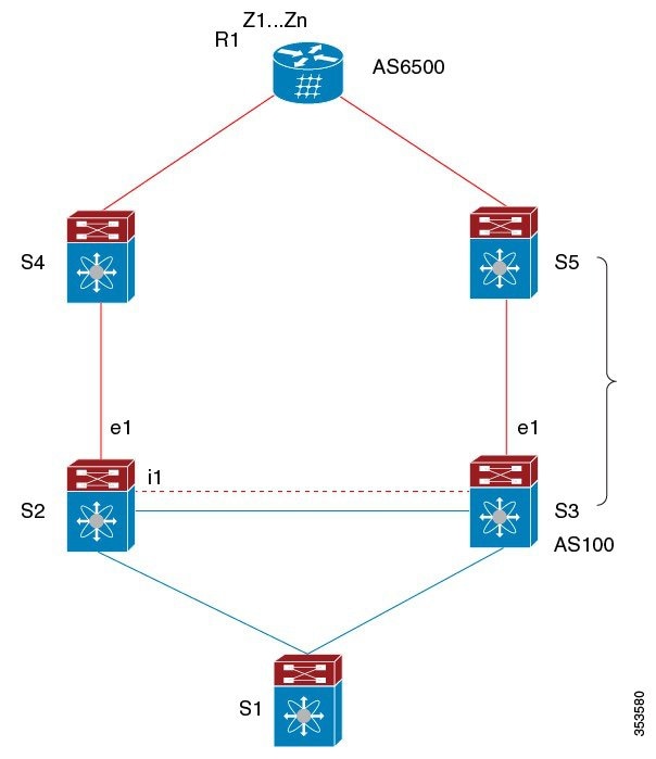
In this figure:
-
eBGP sessions are between S2-S4 and S3-S5.
-
The iBGP session is between S2-S3.
-
Traffic from S1 uses S2 and uses the e1 interface to reach prefixes Z1...Zn.
-
S2 has two paths to reach Z1…Zn:
-
A primary path through S4
-
A backup path through S5
-
In this example, S3 advertises to S2 the prefixes Z1…Zn to reach (with itself as the next hop). With BGP PIC edge enabled, BGP on S2 installs both the best path (through S4) and the backup path (through S3 or S5) toward the AS6500 into the RIB. Then the RIB downloads both routes to the FIB.
If the S2-S4 link goes down, the FIB on S2 detects the link failure. It automatically switches from the primary path to the backup path and points to the new next hop S3. Traffic is quickly rerouted due to the local fast re-convergence in the FIB. After learning of the link failure event, BGP on S2 recomputes the best path (which is the previous backup path), removes next hop S4 from the RIB, and reinstalls S3 as the primary next hop into the RIB. BGP also computes a new backup path, if any, and notifies the RIB. With the support of the BGP PIC edge feature, the FIB can switch to the available backup route instantly upon detection of a link failure on the primary route without waiting for BGP to select the new best path and converge to achieve a fast reroute.
BGP PIC edge with multipath
The following figure shows a BGP PIC edge multipath topology.
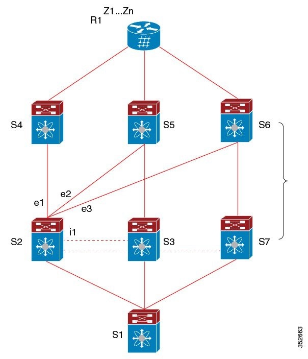
In this topology, there are six paths for a given prefix:
-
eBGP paths: e1, e2, e3
-
iBGP paths: i1, i2, i3
The order of preference is e1 > e2 > e3 > i1 > i2 > i3.
The potential multipath situations are:
-
No multipaths configured:
-
bestpath = e1
-
multipath-set = []
-
backup path = e2
-
PIC behavior: When e1 fails, e2 is activated.
-
-
Two-way eBGP multipaths configured:
-
bestpath = e1
-
multipath-set = [e1, e2]
-
backup path = e3
-
PIC behavior: Active multipaths are mutually backed up. When all multipaths fail, e3 is activated.
-
-
Three-way eBGP multipaths configured:
-
bestpath = e1
-
multipath-set = [e1, e2, e3]
-
backup path = i1
-
PIC behavior: Active multipaths are mutually backed up. When all multipaths fail, i1 is activated.
-
-
Four-way eBGP multipaths configured:
-
– bestpath = e1
-
– multipath-set = [e1, e2, e3, i1]
-
– backup path = i2
-
– PIC behavior: Active multipaths are mutually backed up. When all multipaths fail, i2 is activated.
-
When the Equal Cost Multipath Protocol (ECMP) is enabled, none of the multipaths can be selected as the backup path.
For multipaths with the backup path scenario, faster convergence is not expected with simultaneous failure of all active multipaths.
BGP PIC core
BGP Prefix Independent Convergence (PIC) in Core is a BGP optimization technique that
-
improves BGP convergence speed after a network failure,
-
reduces the time and resources needed to update forwarding information for multiple prefixes, and
-
enables immediate leveraging of IGP convergence by hierarchical FIB programming.
When a link fails on Provider Edge (PE), the Routing Information Base (RIB) updates the Forwarding Information Base (FIB) with new next hop. FIB must update all BGP prefixes that point to the failed next hop and point to the new one. This can be time and resource consuming. With BGP PIC Core enabled, the prefix is programmed in the FIB in a hierarchical way. All prefixes point to the ECMP group instead of the recursive next hop. When the same failure happens, the FIB only needs to update the ECMP group to point to the new next hop without updating prefixes. This gives BGP immediate leveraging of IGP convergence.
BGP PIC feature support matrix
|
BGP PIC |
IPv4 Unicast |
IPv6 Unicast |
|---|---|---|
|
Edge unipath |
Yes |
No |
|
Edge with multipath (multiple active ECMPs, only one backup) |
Yes |
No |
|
Core |
Yes |
Yes |
Note |
The PIC Core (system pic-core command) and PIC Edge must be used exclusively in a Layer 3 environment and are not compatible with VXLAN environment. |
BGP virtualization
BGP supports virtual routing and forwarding (VRF) instances.
 Feedback