IPv4 Addresses
An IP address is a unique identifier assigned to each network interface on a device, allowing communication with other hosts across a network. Configuring IP addresses on network interfaces enables those interfaces to send and receive packets within the network.
An interface can have one primary IP address, which is the main source and destination for packets generated by the device. You can also assign multiple secondary IP addresses to an interface to support multiple subnets or network requirements. All devices on the same interface must share the same primary IP address because outgoing packets always use this primary address as their source. Every IPv4 packet includes source and destination information taken from the configured IP addresses. For more information, see Multiple IPv4 Addresses.
A subnet mask is a 32-bit value that divides an IP address into the network and host portions. By applying a subnet mask, you specify the network to which an IP address belongs and isolate the host component. Subnet masks help IP networks distinguish between network IDs and host IDs, facilitating effective routing and addressing.
The IP feature on the device manages IPv4 packet handling and forwarding, including unicast and multicast route lookup, software-based access control list (ACL) forwarding, and duplicate address detection. It also oversees IP address configuration for network interfaces, static route management, and packet transmission and reception by IP clients.
 Note |
Nexus switches drop packets that are sent to a null0 interface. If an IPv4 or IPv6 packet is sent to a null0 interface, Cisco Nexus 9000 switches do not respond with an ICMP or ICMPv6. |
Multiple IPv4 Addresses
Cisco NX-OS allows you to configure multiple IP addresses for each interface. You can set any number of secondary addresses to meet different requirements. Common scenarios include:
-
When you require more host IP addresses than a single subnet allows. For instance, if your subnetting scheme supports up to 254 hosts per logical subnet but you need 300 hosts on a single physical subnet, you can apply secondary IP addresses on the routers or access servers. This enables you to map two logical subnets onto one physical subnet.
-
When two subnets of the same network are physically separated by another network, you can use a secondary address to unify them. In these cases, one network is effectively extended over another. Note that a subnet must not appear on more than one active interface on the router at any time.
Note |
If any device on a network segment uses a secondary IPv4 address, all other devices on that same interface must use a secondary address from the same network or subnet. Inconsistent application of secondary addresses within the segment can quickly result in routing loops. |
LPM routing modes
By default, Cisco NX-OS programs routes in a hierarchical fashion to allow for the longest prefix match (LPM) on the device. However, you can configure the device for different routing modes to support more LPM route entries.
Theses tables list the LPM routing modes that are supported on Cisco Nexus 9000 Series switches.
LPM routing modes for Cisco Nexus 9200 platform switches
|
LPM routing mode |
CLI command |
|---|---|
|
Default system routing mode |
|
|
LPM dual-host routing mode |
system routing template-dual-stack-host-scale |
|
LPM heavy routing mode |
system routing template-lpm-heavy |
Note |
Cisco Nexus 9200 platform switches do not support the system routing template-lpm-heavy mode for IPv4 Multicast routes. Make sure to reset LPM's maximum limit to 0. |
LPM routing modes for Cisco Nexus 9300 platform switches
|
LPM routing mode |
Broadcom T2 mode |
CLI command |
|---|---|---|
|
Default system routing mode |
3 |
|
|
ALPM routing mode |
4 |
system routing max-mode l3 |
LPM routing modes for Cisco Nexus 9300-EX/FX/FX2/FX3/GX platform switches
|
LPM routing mode |
CLI command |
|---|---|
|
LPM dual-host routing mode |
system routing template-dual-stack-host-scale |
|
LPM heavy routing mode |
system routing template-lpm-heavy |
|
LPM Internet-peering mode |
system routing template-internet-peering |
LPM routing modes for Cisco Nexus 9300-FX platform switches
LPM routing modes for Cisco Nexus 9300-fx2 platform switches
LPM routing modes for Cisco Nexus 9300-GX platform switches
LPM routing modes for Cisco Nexus 9500 platform switches with 9700-ex and 9700-fx line cards
|
LPM routing mode |
Broadcom T2 mode |
CLI command |
||
|---|---|---|---|---|
|
Default system routing mode |
3 (for line cards); 4 (for fabric modules) |
|||
|
Max-host routing mode |
2 (for line cards); 3 (for fabric modules) |
system routing max-mode host |
||
|
Nonhierarchical routing mode |
3 (for line cards); 4 with max-l3-mode option (for line cards) |
system routing non-hierarchical-routing [max-l3-mode] |
||
|
64-bit ALPM routing mode |
Submode of mode 4 (for fabric modules) |
system routing mode hierarchical 64b-alpm |
||
|
LPM heavy routing mode |
system routing template-lpm-heavy
|
|||
|
LPM Internet-peering mode |
system routing template-internet-peering
|
|||
|
LPM dual-host routing mode |
LPM routing modes for Cisco Nexus 9500-R platform switches with 9600-R line cards
|
LPM routing Mode |
CLI command |
|---|---|
|
LPM Internet-peering mode |
system routing template-internet-peering (Cisco NX-OS release 9.3(1) and later) |
Host to LPM Spillover
Beginning with Cisco NX-OS Release 7.0(3)I5(1), you can store host routes on the longest prefix match (LPM) table to achieve a larger host scale.
In a LPM mode, the switch supports fewer host routes. If you add more host routes than the supported scale, the excess routes from the host table occupy space in the LPM table, which reduces the total number of LPM routes available. This feature is supported on Cisco Nexus 9300 and 9500 platform switches.
In the default system routing mode, Cisco Nexus 9300 platform switches are set for higher host scale and fewer LPM routes, allowing the LPM space to be used for additional host routes. On Cisco Nexus 9500 platform switches, this feature is supported on line cards only in the default system routing and nonhierarchical routing modes. Fabric modules do not support this feature.
Address Resolution Protocol
Networking devices and Layer 3 switches use Address Resolution Protocol (ARP) to map IP addresses (network layer) to Media Access Control (MAC) address (physical layer) to enable IP packets to be sent across networks.
Before a device sends a packet to another device, it looks in its own ARP cache to see if there is a MAC address and corresponding IP address for the destination device. If there is no entry, the source device sends a broadcast message to every device on the network.
Each device compares the IP address to its own. Only the device with the matching IP address replies to the device that sends the data with a packet that contains the MAC address for the device. The source device adds the destination device MAC address to its ARP table for future reference, creates a data-link header and trailer that encapsulates the packet, and proceeds to transfer the data. The following figure shows the ARP broadcast and response process.

When the destination device lies on a remote network that is beyond another device, the process is the same except that the device that sends the data sends an ARP request for the MAC address of the default gateway. After the address is resolved and the default gateway receives the packet, the default gateway broadcasts the destination IP address over the networks connected to it. The device on the destination device network uses ARP to obtain the MAC address of the destination device and delivers the packet. ARP is enabled by default.
The default system-defined CoPP policy rate limits ARP broadcast packets bound for the supervisor module. The default system-defined CoPP policy prevents an ARP broadcast storm from affecting the control plane traffic but does not affect bridged packets.
ARP cache
The Address Resolution Protocol (ARP) cache is a table maintained by network devices such as routers and switches to store mappings between IP addresses and their corresponding MAC hardware addresses.
ARP cache minimizes broadcasts and limits wasteful use of network resources. The mapping of IP addresses to MAC addresses occurs at each hop (device) on the network for every packet sent over an internetwork, which can affect network performance.
-
ARP caching stores network addresses and the associated data-link addresses in the memory for a period of time, which minimizes the use of valuable network resources to broadcast for the same address each time that a packet is sent.
-
You must maintain the cache entries that are set to expire periodically because the information might become outdated.
-
Every device on a network updates its tables as addresses are broadcast.
Static and dynamic entries in the ARP Cache
Static route
Static routing requires you to configure the IP addresses, subnet masks, gateways, and corresponding MAC addresses for each interface of each device.
Static routing requires more work to maintain the route table. You must update the table each time you add or change routes.
Dynamic route
Dynamic routing uses protocols that enable the devices in a network to exchange routing table information with each other.
Dynamic routing is more efficient than static routing because the route table is automatically updated unless you add a time limit to the cache. The default time limit is 25 minutes, but you can modify the time limit if the network has many routes that are added and deleted from the cache.
Devices that do not use ARP
When a network is segmented into two parts, a bridge connects these segments and filters traffic based solely on MAC addresses. The bridge maintains its own MAC address table to manage this filtering. In contrast, a device maintains an ARP cache that maps both IP addresses and their corresponding MAC addresses.
Passive hubs serve as central connection points that physically link devices within a network. Operating at Layer 1 (the physical layer), they broadcast incoming messages to all ports without maintaining any address table.
Layer 2 switches determine which port of a device receives a message that is sent only to that port. However, Layer 3 switches are devices that build an ARP cache (table).
Reverse ARP
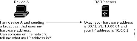
Reverse ARP (RARP) works the same way as ARP, except that the RARP request packet requests an IP address instead of a MAC address. RARP is defined by RFC903.
RARP often is used by diskless workstations because this type of device has no way to store IP addresses to use when they boot. The only address that is known is the MAC address because it is burned into the hardware. Use of RARP requires an RARP server on the same network segment as the router interface. The Reverse ARP figure shows how RARP works.
RARP has several limitations. Because of these limitations, most businesses use Dynamic Host Configuration Protocol (DHCP) to assign IP addresses dynamically. DHCP is cost effective and requires less maintenance than RARP.
These are the most important limitations:
-
Because RARP uses hardware addresses, if the internetwork is large with many physical networks, a RARP server must be on every segment with an additional server for redundancy. maintaining two servers for every segment is costly.
-
Each server must be configured with a table of static mappings between the hardware addresses and IP addresses. Maintenance of the IP addresses is difficult.
-
RARP only provides IP addresses of the hosts and not subnet masks or default gateways.
Proxy ARP
Proxy ARP is a feature that allows a device, typically a router, to answer ARP requests on behalf of another device. This allows a host to communicate with devices on remote subnets without needing to configure routing or a default gateway.
These are the advantages of proxy ARP:
-
Proxy ARP enables a device that is physically located on one network to be logically part of a different physical network connected to the same device or firewall.
-
Proxy ARP allows you to hide a device with a public IP address on a private network behind a router, yet still have the device appear to be on the public network in front of the router. By hiding its identity, the router accepts responsibility for routing packets to the real destination.
-
Proxy ARP can help devices on a subnet reach remote subnets without configuring routing or a default gateway.
When devices are not in the same data link layer network but in the same IP network, they try to transmit data to each other as if they are on the local network. However, the router that separates the devices does not send a broadcast message because routers do not pass hardware-layer broadcasts and the addresses cannot be resolved.
When you enable proxy ARP on the device and it receives an ARP request, it identifies the request as a request for a system that is not on the local LAN. The device responds as if it is the remote destination for which the broadcast is addressed, with an ARP response that associates the device’s MAC address with the remote destination's IP address. The local device believes that it is directly connected to the destination, while in reality its packets are being forwarded from the local subnetwork toward the destination subnetwork by their local device. By default, proxy ARP is disabled.
Local proxy ARP
Local proxy ARP enables a device to respond to ARP requests for IP addresses within a subnet where normally no routing is required.
When you enable local proxy ARP, ARP responds to all ARP requests for IP addresses within the subnet and forwards all traffic between hosts in the subnet. Use this feature only on subnets where hosts are intentionally prevented from communicating directly by the configuration on the device to which they are connected.
Gratuitous ARP
Gratuitous ARP sends a request with an identical source IP address and a destination IP address to detect duplicate IP addresses.
Cisco NX-OS supports enabling or disabling gratuitous ARP requests or ARP cache updates.
Periodic ARP refresh on MAC delete
The ARP process tracks the MAC deletes and sends the periodic ARP Refresh on the L3 VLAN interface in a configured interval of time for the configured count. If the MAC is learned, ARP process stops sending the periodic ARP Refreshes.
For more information, see Configuring periodic ARP refresh on MAC delete for SVIs.
ARP refresh on MAC Delete
MAC addresses are deleted or flushed when triggers such as interface flaps, clearing the MAC address table, or STP TCN notifications occur. Once the MAC addresses are deleted, the ARP process initiates ARP Refresh for all adjacencies associated with these MAC addresses. These ARP Refreshes are subject to CoPP limits, which can prevent the ARP process from effectively relearning all ARP entries.
Beginning with Cisco NX-OS Release 10.5(3)F, instead of sending Refresh retries at 2, 4, 8 seconds and deleting after 16 seconds (if no response is received), the ARP process sends the Refreshes at 2, 4, 8, and 8 seconds, and deletes after an additional 8 seconds (one extra Refresh). This change improves ARP learning with scaled ARP entries, even if some ARP response packets are subject to CoPP limits.
Glean throttles
Glean throttling is a mechanism where, if an Address Resolution Protocol (ARP) request for the next-hop IP address is not resolved by a line card when forwarding incoming IP packets, the line card forwards those packets to the supervisor for resolution. The supervisor resolves the MAC address for the next hop and programs the hardware.
When an ARP request is sent, the software adds a /32 drop adjacency in the hardware to prevent the packets to the same next-hop IP address to be forwarded to the supervisor. When the ARP is resolved, the hardware entry is updated with the correct MAC address. If the ARP entry is not resolved before a timeout period, the entry is removed from the hardware.
Note |
Glean throttling is supported for IPv4 and IPv6, but IPv6 link-local addresses are not supported. |
Path MTU discovery
Path maximum transmission unit (MTU) discovery is a method for maximizing the use of available bandwidth in the network between the endpoints of a TCP connection.
It is described in RFC 1191. Existing connections are not affected when this feature is turned on or off.
ICMP
You can use the Internet Control Message Protocol (ICMP) to provide message packets that report errors and other information that is relevant to IP processing.
ICMP generates error messages, such as ICMP destination unreachable messages, ICMP Echo Requests (which send a packet on a round trip between two hosts) and Echo Reply messages. ICMP also provides many diagnostic functions and it can send and redirect error packets to the host. By default, ICMP is enabled.
Some of the ICMP message types are as follows:
-
Network error messages
-
Network congestion messages
-
Troubleshooting information
-
Timeout announcements
Note |
|
 Feedback