|
1. Install the standby cluster in AZ2.
|
Install using your preferred method:
Verify if the installation was successful, and log into the Cisco Crosswork UI.
|
|
(Optional) 2. Install the arbiter VM in AZ3.
|
Note
|
Please skip this step if you do not wish to use the auto arbitration functionality.
|
|
Follow the instructions in Deploy the Arbiter VM.
|
|
3. (Optional) Import the Crosswork inventory.
|
If you want to perform node-related activities (such as adding or removing a node) from the Crosswork UI, you must manually
import a cluster inventory (.yaml) file into the Crosswork UI. For more information, see Import Cluster Inventory.
|
|
4. Create a backup of your Crosswork clusters.
|
Follow the instructions in Manage Backups chapter in Cisco Crosswork Network Controller 7.2 Administration Guide.
|
Note
|
Importing the cross cluster inventory template cannot be undone if there is no pre-existing backup of the system before the
template is loaded.
|
|
|
5. Perform the connectivity checks.
|
Follow the instructions in Connectivity Checks topic.
|
|
6. Prepare the cross cluster inventory file and enable geo redundancy.
|
Follow the instructions in Enable Geo Redundancy topic.
|
|
7. Install and enroll Crosswork Data Gateway, and onboard devices.
|
You can choose one of these approaches for AZ2 setup:
Follow this workflow to deploy a new Data Gateway.
-
Choose the deployment profile for the Data Gateway VM. See Crosswork Cluster VM Requirements.
|
Note
|
If you are redeploying the same Data Gateway with Crosswork Network Controller, delete the previous Data Gateway entry from
the Virtual Machine table under Data Gateway Management. For information on how to delete a Data Gateway VM, see Delete the Data Gateway VM from Cisco Crosswork.
|
-
Review the installation parameters to ensure that you have all the required information to install the Data Gateway. See Crosswork Data Gateway Parameters and Deployment Scenarios.
|
Note
|
Use an FQDN, for example, geomanagement.cw.cisco, as the unified multi-cluster domain name. Ensure this FQDN is reachable
from both clusters and points to the Active Crosswork VIP in the Geo-HA DNS server. If these conditions are not met, Data
Gateway instance enrollment will fail.
|
-
Install the Data Gateway using your preferred method:
-
Verify the Data Gateway enrollment. See Crosswork Data Gateway Authentication and Enrollment.
|
Note
|
Use an FQDN such as geomanagement.cw.cisco that is reachable from both clusters and points to the Active Crosswork VIP in
the Geo-HA DNS server; otherwise, the enrollment will fail.
|
-
After the installation is complete, perform the postinstallation procedure. See Crosswork Data Gateway Post-installation Tasks.
-
Repeat steps 1 to 5 in the workflow to install Data Gateways on both standby sites.
-
Assign the Data Gateways to standby site. For more information. see the Assign Data Gateways to geo redundancy-enabled sites section in the Cisco Crosswork Network Controller 7.2 Administration Guide.
-
Add the new Data Gateways to the existing pool. For more information, see the Edit or delete a Data Gateway pool section in the Cisco Crosswork Network Controller 7.2 Administration Guide.
|
|
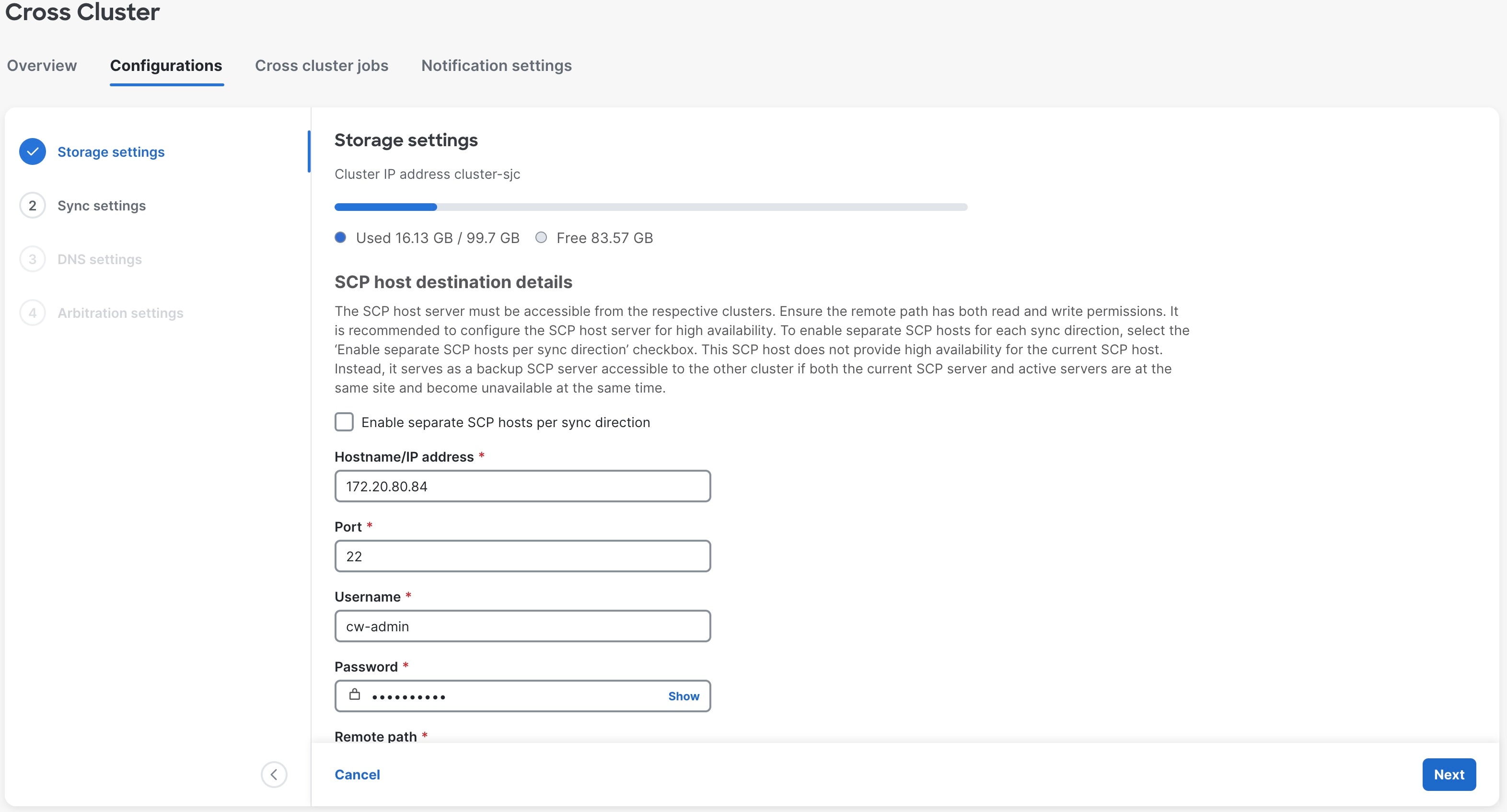
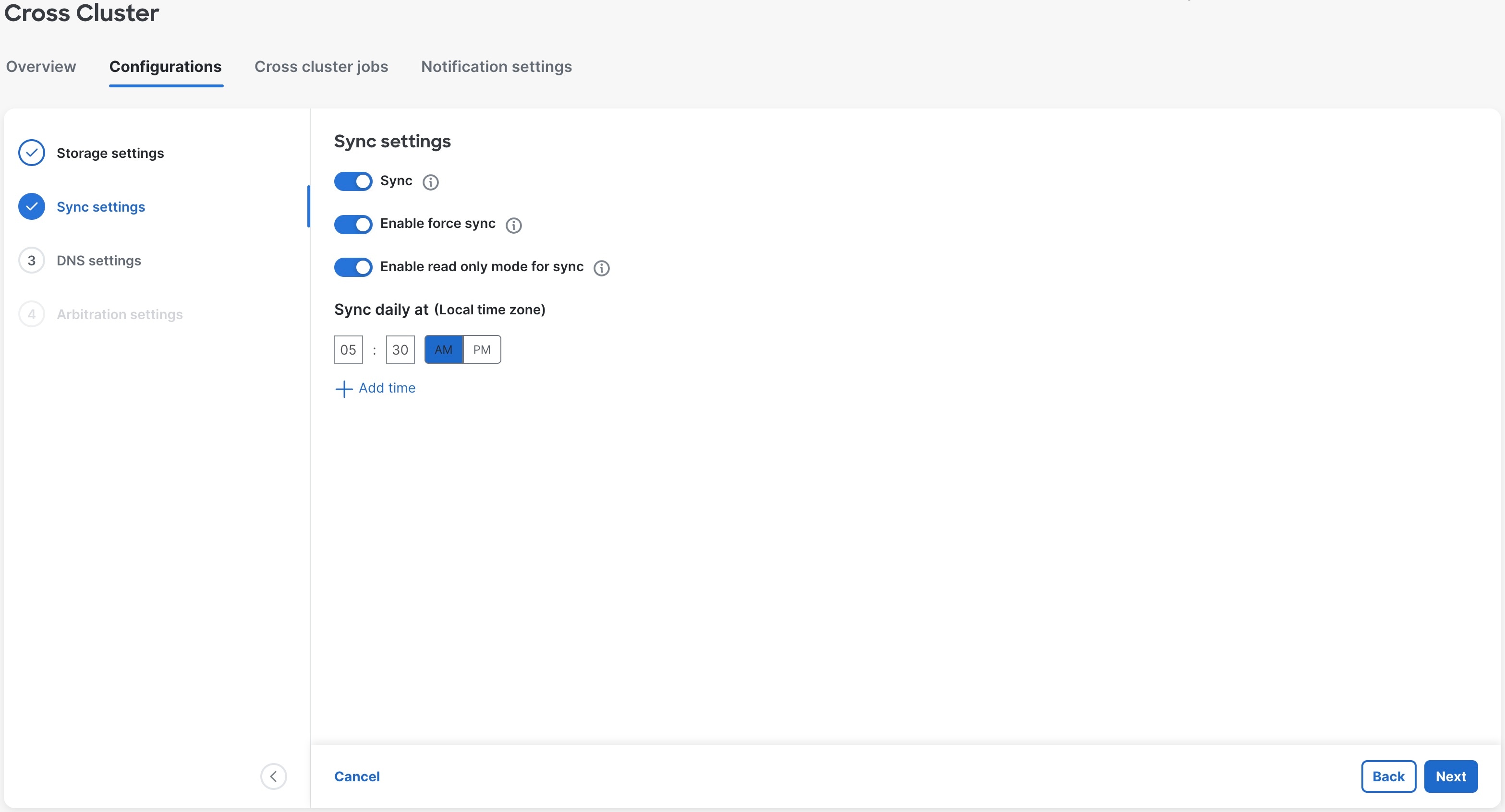
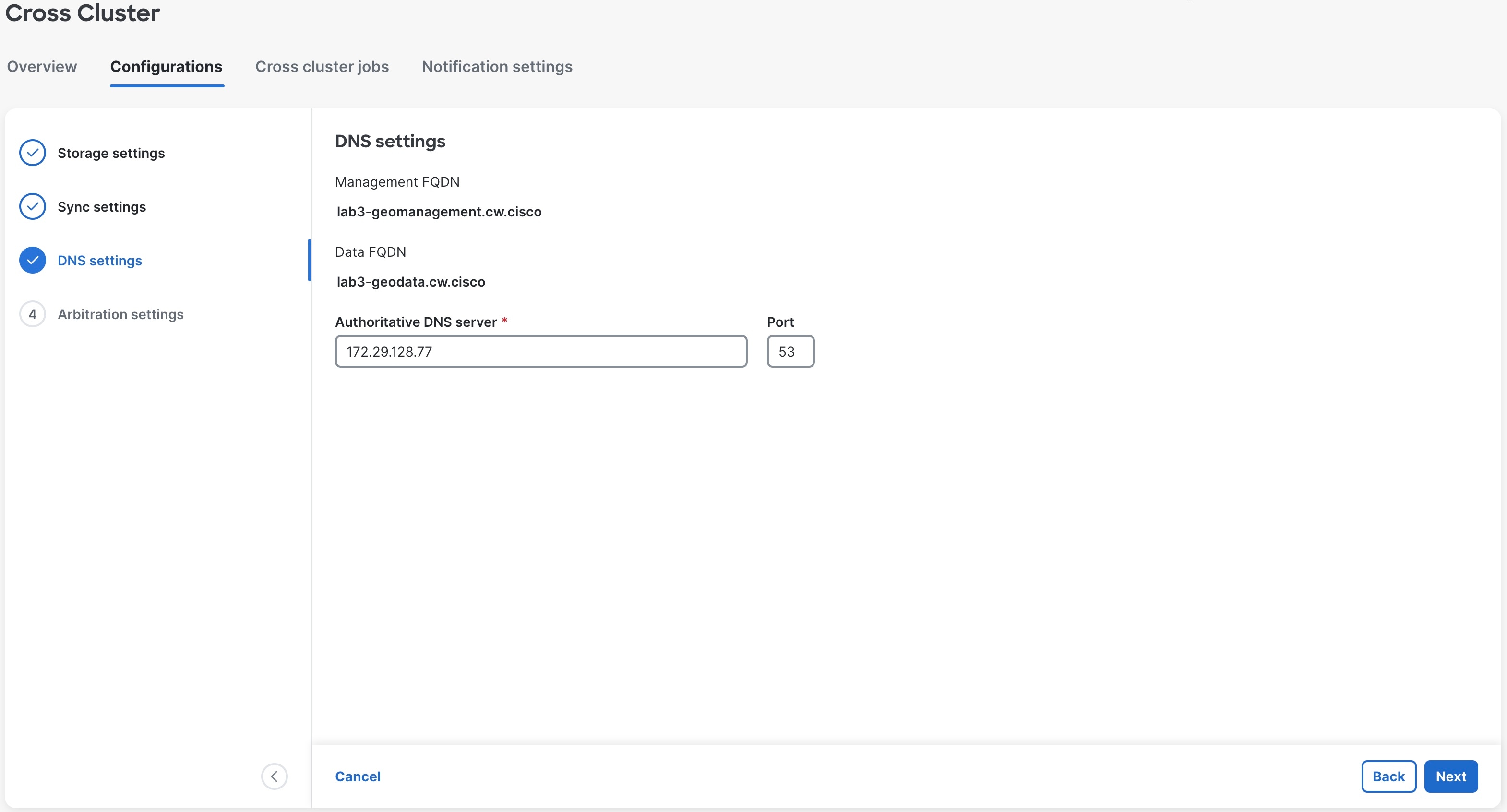
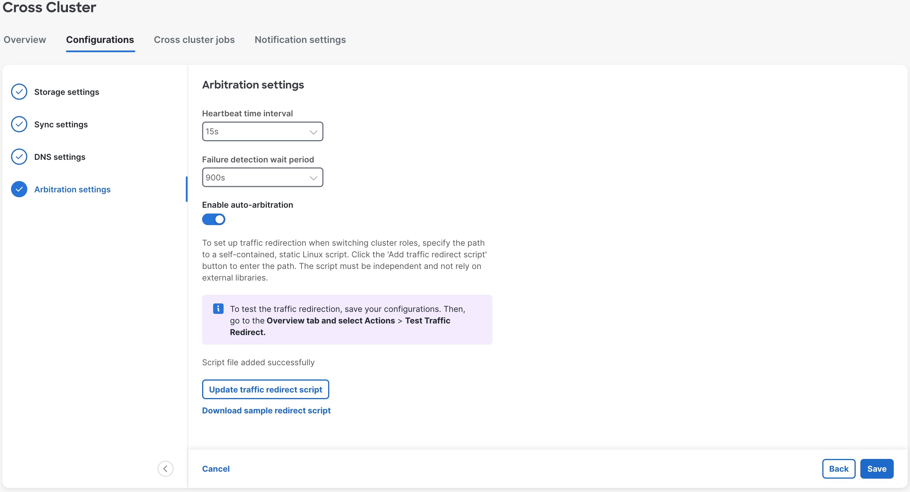
8. Configure the cross cluster settings.
|
Follow the instructions in topics below:
|
|
9. Complete an on-demand sync operation successfully.
|
On the Cross Cluster window, select to initiate the sync operation.
|
|
10. Install the Crosswork Applications on the active cluster.
|
Follow the instructions in Install Crosswork Network Controller applications topic.
Once geo redundancy is enabled, a Geo Redundancy tile is added to the Application management window. This tile is built-in and cannot be upgraded, uninstalled, or deactivated.
|
Warning
|
-
Parallel installation of applications on the active and standby clusters should be avoided. Complete the installation on the
active cluster before proceeding with the installation on the standby cluster.
-
Applications should not be installed during a periodic or on-demand sync operation. Ensure there is sufficient time for the
installation to complete before initiating a sync, and verify that no sync operation is in progress before installing an application.
It is recommended to temporarily disable periodic sync when installing applications.
|
|
|
11. Install the Crosswork Applications on the standby cluster.
|
Note
|
Applications on the standby site remain in a degraded state until the first sync completes.
|
|
|
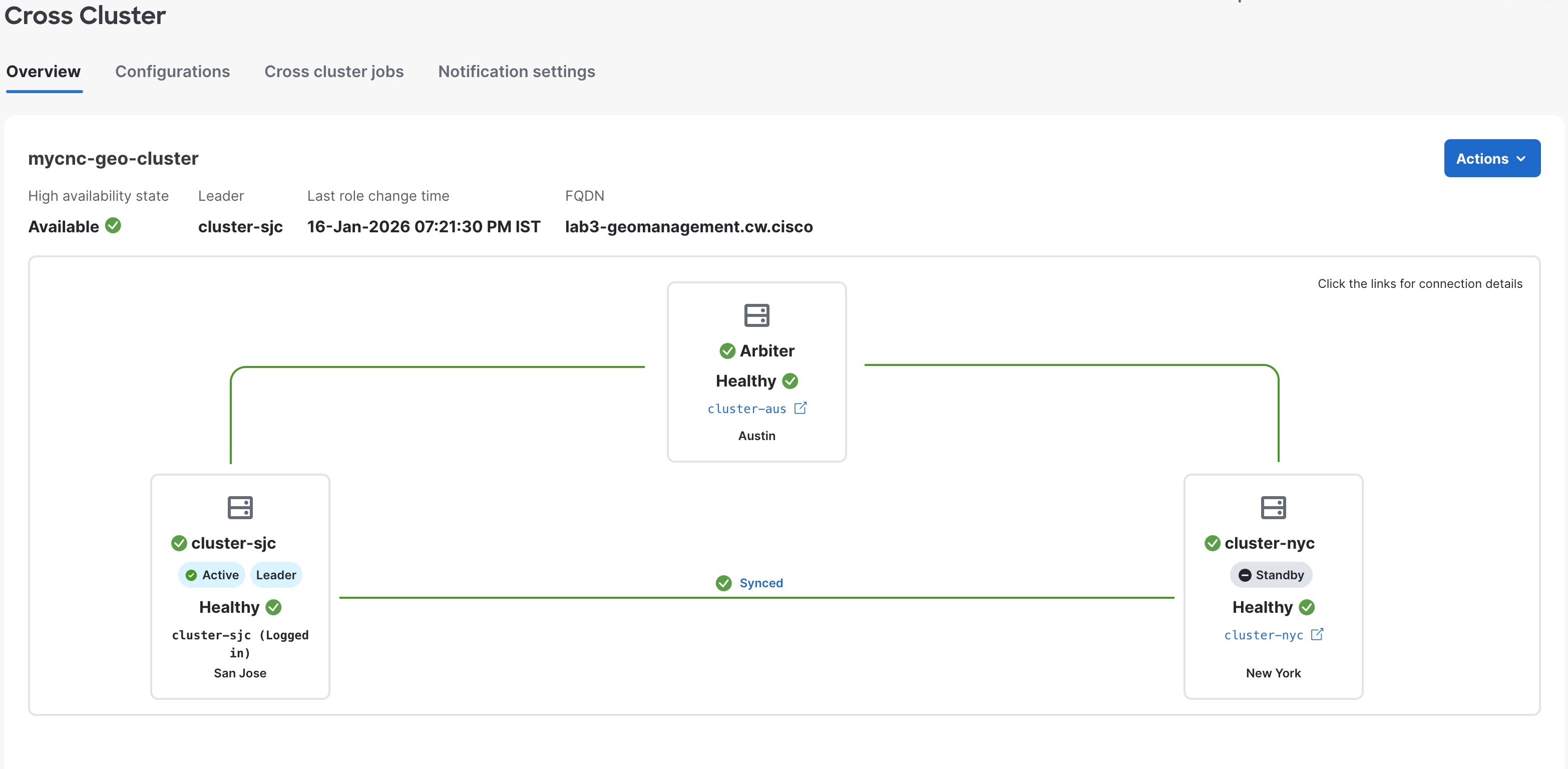
12. Verify that the geo redundancy was successfully enabled on the active and standby clusters.
|
Perform these checks:
-
In the Cross Cluster Health Status, ensure the operational state is Connected.
-
In the Cross Cluster Health Status, ensure that active cluster state is Healthy.
-
In the Cross Cluster Health Status, ensure that standby cluster state is Healthy.
-
In the Cross Cluster Health Status, ensure the High Availability state is AVAILABLE.
-
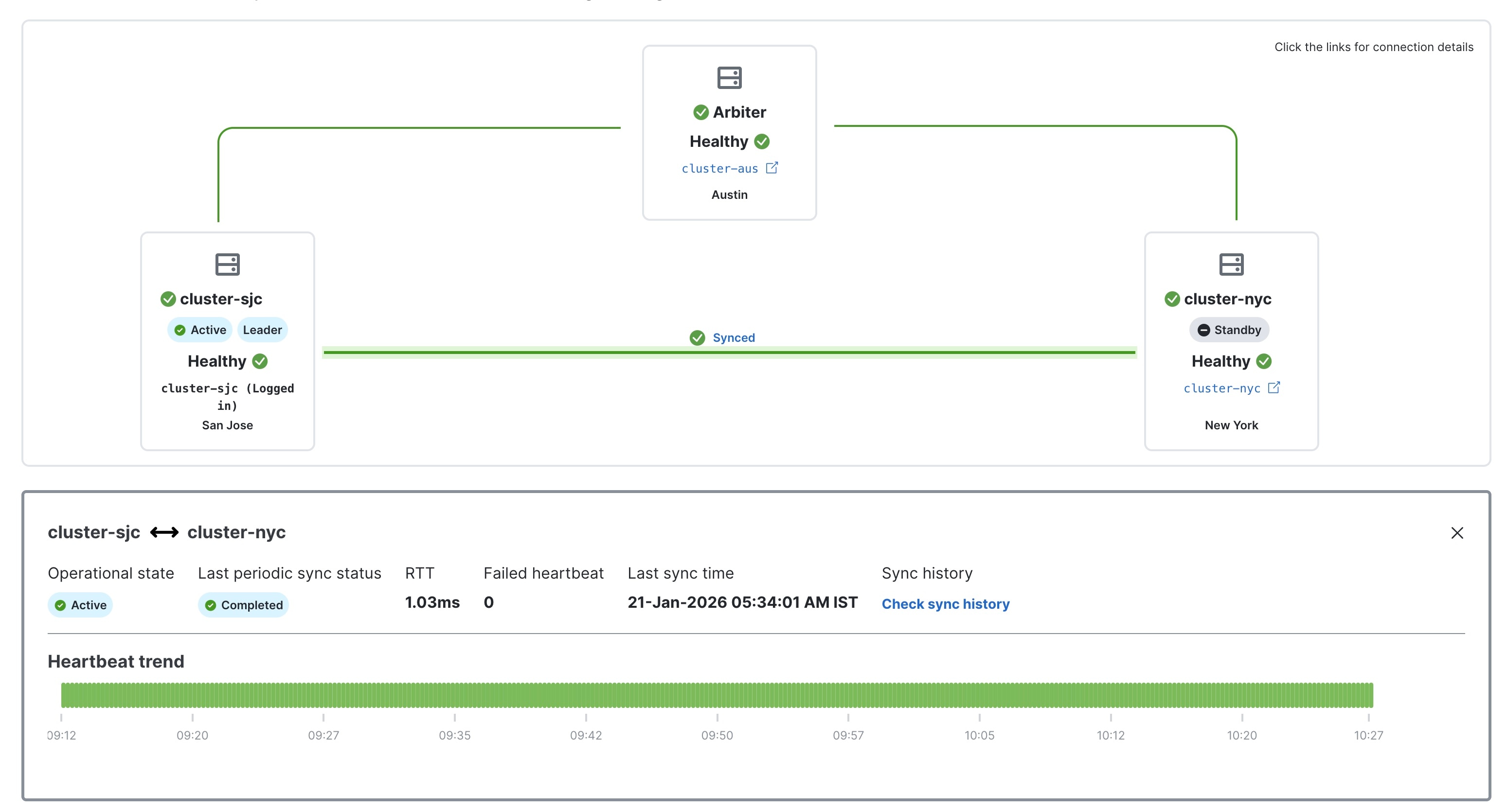
Verify that the heartbeat count between the clusters is incrementing and that no failures are observed over a 30-minute period.
-
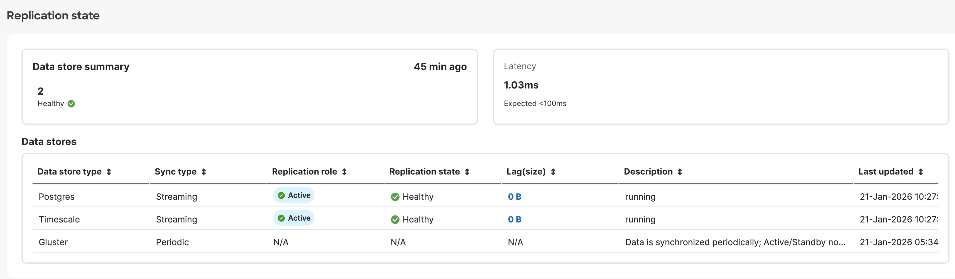
Confirm the completion of one successful sync between the clusters.
For more information, see View Cross Cluster Status topic.
|
|
Onboard the arbiter VM
|
|
13. Update the cross cluster inventory file, and enable geo redundancy on the arbiter VM.
|
Follow the instructions in Enable Geo Redundancy topic.
Perform these steps:
-
Import the active cluster inventory.
-
Import the standby cluster inventory.
-
Enable geo redundancy on the arbiter VM.
|
|
14. Configure the cross cluster settings
|
Follow the instructions in topics below:
|
|
15. Verify that the geo redundancy was successfully enabled on all the AZs.
|
Note
|
During a Day-N arbiter reimport on the active cluster, the Cross Cluster page may temporarily show the link to the standby
cluster as disconnected and the standby state as unknown. This is expected behavior. Arbiter reimport is a multi-step process
that involves component restarts, and the cluster states remain in transition during this period. The system converges automatically,
and there is no functional impact.
|
|
Perform these checks:
-
In the Cross Cluster Health Status, ensure the operational state is Connected.
-
In the Cross Cluster Health Status, ensure that active cluster state is Healthy.
-
In the Cross Cluster Health Status, ensure that standby cluster state is Healthy.
-
In the Cross Cluster Health Status, ensure that arbiter VM state is Healthy.
-
In the Cross Cluster Health Status, ensure the High Availability state is AVAILABLE.
-
Verify that the heartbeat count between the clusters is incrementing and that no failures are observed over a 30-minute period.
-
Confirm the completion of one successful sync between the clusters.
For more information, see View Cross Cluster Status topic.
|


 Feedback