The following configurations are examples to guide you in a multiple SR-PCE setup for HA. Please modify accordingly.
ISIS single topology configuration for dual-stack networks
Cisco Crosswork Network Controller supports ISIS Single Topology in addition to Multi-Topology. To utilize this, your XTC
devices must be configured for ISIS Single Topology. For Single Topology configurations, only global IPv6 addressing is supported;
support for link-local IPv6 addressing is not included.
Device-side configuration example
RP/0/RP0/CPU0:iosxrv-2(config)#router isis [NAME]
RP/0/RP0/CPU0:iosxrv-2(config-isis)#address-family ipv6 unicast
RP/0/RP0/CPU0:iosxrv-2(config-isis-af)#single-topology
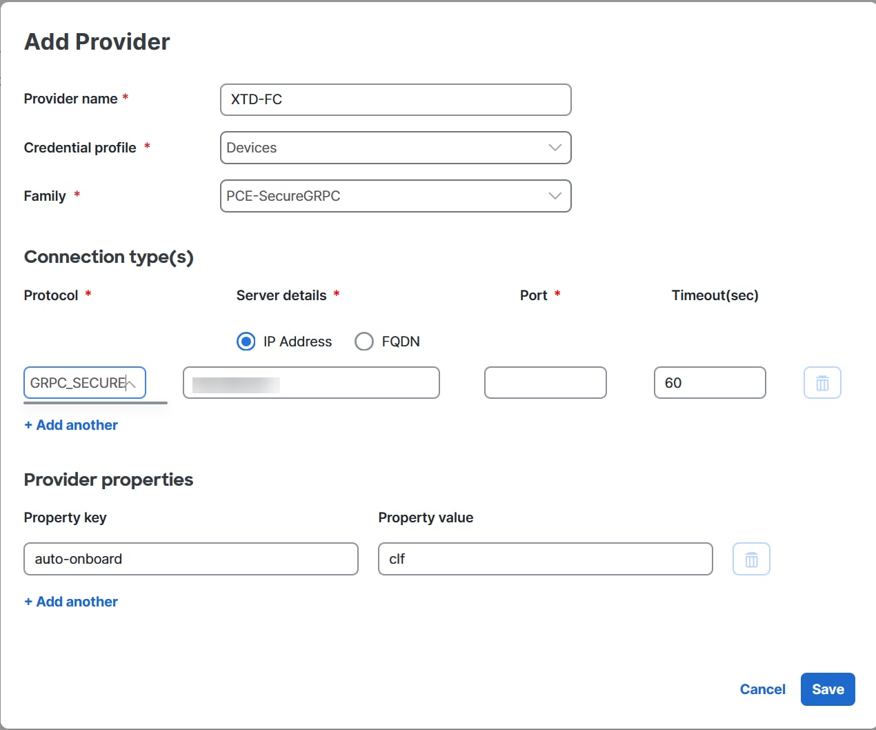
Configuration requirements for deploying and reporting SR MSL policies to PCE
Enable gRPC on devices and for SR-TE policies
RP/0/RP0/CPU0:L1-NCS5501#sh running-config grpc
grpc
segment-routing
traffic-eng
policy-service
!
!
port 57400
no-tls
Advertise all SR policies to BGP-LS peers
This configuration enables your router to report all configured SR MSL policies—both active and inactive—into the link-state
database. As a result, these policies can be advertised via BGP-LS to controllers or peers, providing full visibility and
supporting network orchestration.
RP/0/RP0/CPU0:L1-NCS5501#sh running-config segment-routing traffic-eng distribute link-state
segment-routing
traffic-eng
distribute link-state
report-candidate-path-inactive
!
!
!
Prevent reporting MSL policies in PCEP
This configuration prevents SR MSL policies from being reported via PCEP. Since PCEP does not fully support MSL policies (it
only advertises a single segment list, which can cause operational issues), it is recommended to remove the report-all command
from the PCC configuration on the headend router.
RP/0/RP0/CPU0:L4-NCS560#sh running-config segment-routing traffic-eng pcc
segment-routing
traffic-eng
pcc
source-address ipv4 192.100.0.4
pce address ipv4 100.100.0.1
precedence 25
!
pce address ipv4 100.100.0.2
precedence 50
!
! Remove the following line to prevent reporting MSL policies to PCE
! report-all
redundancy pcc-centric
profile 1981
autoroute
include ipv4 all
force-sr-include
!
!
!
!
!
Advertise SR MSL policies in link-state to PCE neighbor via BGP-LS
This configuration enables your router to advertise SR MSL policies in the link-state address family to a PCE neighbor over
BGP. By establishing a BGP session with the PCE and including the address-family link-state link-state configuration, the router ensures that SR MSL policies are advertised and can be learned by the PCE.

Note
|
The link-state address family must be configured on both the headend and the PCE for successful exchange.
|
RP/0/RP0/CPU0:L1-NCS5501#sh running-config router bgp
router bgp 60
neighbor <NEIGHBOR_IP> ! PCE neighbor
remote-as 60
update-source Loopback0
address-family ipv4 unicast
next-hop-self
!
address-family ipv6 unicast
!
address-family link-state link-state. ! Enable BGP-LS for SR MSL policy advertisement
!
!
SRv6 data collection and traffic steering for DDM (Deterministic Demand Matrix) integration on Cisco IOS XR
Enable SRv6 locator accounting
This configuration enables the router to perform detailed accounting for IPv6 traffic specifically related to SRv6 locators.
By tracking traffic on a per-prefix and per-nexthop basis, operators gain granular visibility into the usage and flow of SRv6-enabled
services.
RP/0/RP0/CPU0:L1-NCS5501#sh running-config accounting
accounting
prefixes
ipv6
mode per-prefix per-nexthop srv6-locators
!
!
!
Enable SRv6 accounting data to telemetry
This configuration sets up model-driven telemetry on the router to stream SRv6 accounting data to external collectors. By
defining specific sensor paths, the router can push operational data related to SRv6 locator accounting, enabling real-time
monitoring, analysis, and orchestration of SRv6 network performance and traffic patterns.
RP/0/RP0/CPU0:L1-NCS5501#sh running-config telemetry model-driven
telemetry model-driven
sensor-group cisco_models
sensor-path Cisco-IOS-XR-infra-xtc-agent-oper:xtc/forwarding/policy-forwardings/policy-forwarding
sensor-path Cisco-IOS-XR-fib-common-oper:cef-accounting/vrfs/vrf[vrf-name='default']/afis/afi[afi-type=ipv6]/pfx/srv6locs/srv6loc
!
!
Enable customer/VRF traffic steering to SRv6 locators via BGP
This configuration enables an edge router to steer customer or VRF (Virtual Routing and Forwarding) IPv4 and IPv6 traffic
into specific SRv6 locators using BGP.
RP/0/RP0/CPU0:L1-NCS5501#sh running-config router bgp
router bgp 60
bgp router-id <ROUTER_ID_IP>
segment-routing srv6
locator L1algo0
!
address-family ipv4 unicast
network <ROUTER_ID_IP>/32
!
address-family vpnv4 unicast
vrf all ! If there are multiple VRF where traffic is ingressing, add srv6 locator in vrf all.
segment-routing srv6
locator L1algo0
alloc mode per-vrf
!
!
!
vrf ntt
rd 200:200
address-family ipv4 unicast
segment-routing srv6 ! If there is only one VRF where traffic is ingressing, add srv6 locator in this vrf alone, if there is no VRF, then add the locator in neighbor address family
locator L1algo0
alloc mode per-vrf
!
redistribute connected
!
neighbor <NEIGHBOR_IP>
remote-as 61
update-source GigabitEthernet0/0/0/0
address-family ipv4 unicast
route-policy PASS_ALL in
route-policy PASS_ALL out
!
!
!
Verify SRv6 traffic steering via CEF accounting
This command is used to verify that IPv6 traffic is being steered into SRv6 locators, rather than MPLS labels, by inspecting
the CEF accounting statistics. It provides granular visibility, showing packet and byte counts for specific IPv6 prefixes
that are associated with SRv6 locators.
sh cef ipv6 accounting
fccc:cc3e:3::/48
Accounting: 0/0 packets/bytes output (per-prefix-per-path mode)
via fe80::2/128, Bundle-Ether1201
path-idx 0
next hop fe80::2/128
Accounting: 200000/58400000 packets/bytes output <<< Traffic packets for prefix fccc:cc3e:3::
Other sample SR-PCE configurations
Redundant SR-PCE configuration (on PCE with Cisco IOS-XR 7.x.x)
pce
address ipv4 100.100.0.7
state-sync ipv4 100.100.0.1
api
sibling ipv4 100.100.0.1
PCE configuration for enabling gRPC API on XR 25.2.1.x (IPv4 deployment)
conf t
lslib-server
 !
grpc
port 57400
no-tls
address-family ipv4
service-layer
!
!
pce
distribute link-state
!
!
linux networking
 vrf default
  address-family ipv4
   default-route software-forwarding
!
address-family ipv6
default-route software-forwarding
!
!
!
commit
Note
|
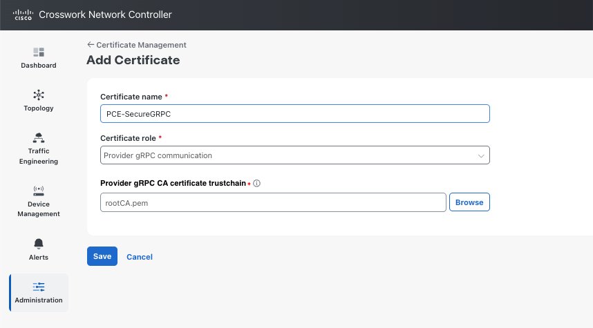
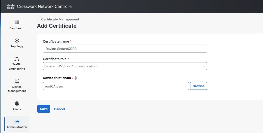
For secure gRPC deployment, remove no-tls.
Configure distribute link-state on all PCEs to inject SR policies into BGP-LS.
|
Enable gRPC API on XR 25.2.1.x (IPv6 deployment)
conf t
  lslib-server
  !
  grpc
    port 57400
    no-tls
    address-family ipv6
    service-layer
    !
!
pce
  distribute link-state
  !
!
linux networking
  vrf default
    address-family ipv4
      default-route software-forwarding
    !
    address-family ipv6
      default-route software-forwarding
    !
  !
!
commit
Note
|
For secure gRPC deployment, remove no-tls.
Configure distribute link-state on all PCEs to inject SR policies into BGP-LS.
|
Verify whether the topology is published in gRPC
sh lslib server topology-db
Verify the SR-MPLS LSP published in gRPC
show lslib server topology-db detail protocol sr
Redundant SR-PCE configuration (PCC)
segment-routing
 traffic-eng
  pcc
   source-address ipv4 100.0.0.1
   pce address ipv4 100.0.0.2
    precedence 200
   !
   pce address ipv4 100.0.0.3
    precedence 100
   !
   report-all
   redundancy pcc-centric
Redundant SR-PCE configuration (on PCC) for RSVP-TE
Note
|
Loopback0 represents the TE router ID.
|
ipv4 unnumbered mpls traffic-eng Loopback0
!
mpls traffic-eng
 pce
  peer source ipv4 200.100.200.1
  peer ipv4 209.165.0.6
   precedence 200
  !
  peer ipv4 100.100.0.0
   precedence 100
  !
  stateful-client
   instantiation
   report
   redundancy pcc-centric
   autoroute-announce
  !
 !
 auto-tunnel pcc
  tunnel-id min 1000 max 1999
 !
!
Sample Telemetry configuations
SR-TM configuation
telemetry model-driven
 destination-group crosswork
  address-family ipv4 5.5.5.5 port 9000
   encoding self-describing-gpb
   protocol tcp
  !
 !
 sensor-group SRTM
  sensor-path Cisco-IOS-XR-infra-tc-oper:traffic-collector/afs/af/counters/tunnels
  sensor-path Cisco-IOS-XR-infra-tc-oper:traffic-collector/vrf-table/default-vrf/afs/af/counters/prefixes
 !
 subscription OE
  sensor-group-id SRTM sample-interval 60000
  destination-id crosswork
  source-interface Loopback0
!
traffic-collector
 interface GigabitEthernet0/0/0/3
 !
 statistics
  history-size 10
Note
|
The destination address uses the southbound data interface (eth1) address of the Crosswork Data Gateway VM.
|
It is required to push sensor path on telemetry configuration via NSO to get prefix and tunnel counters. It is assumed that
the Traffic Collector has been configured with all the traffic ingress interface. This configuration is needed for demands
in the Bandwidth on Demand feature pack to work.
Telemetry sensor path
sensor-path Cisco-IOS-XR-infra-tc-oper:traffic-collector/afs/af/counters/tunnels/tunnel
sensor-path Cisco-IOS-XR-infra-tc-oper:traffic-collector/vrf-table/default-vrf/afs/af/counters/prefixes/prefix
Telemetry configuration pushed by Crosswork Network Controller to all the headend routers via NSO
telemetry model-driven
  destination-group CW_43dc8a5ea99529715899b4f5218408a785e40fce
    vrf default
    address-family ipv4 5.5.5.5 port 30500
      encoding self-describing-gpb
      protocol top
    !
  !
destination-group CW_4b3c69a200668b0a8dc155caff295645c684a8f8
  vrf default
  address-family ipv4 5.5.5.5 port 30500
    encoding self-describing-gpb
    protocol top
  !
!
sensor-group CW_43dc8a5ea99529715899b4f5218408a785e40fce
  sensor-path Cisco-IOS-XR-infra-tc-oper:traffic-collector/afs/af/counters/tunnels/tunnel
!
sensor-group CW_4b3c69a200668b0a8dc155caff295645c684a8f8
  sensor-path Cisco-IOS-XR-infra-tc-oper:traffic-collector/vrf-table/default-vrf/afs/af/counters/prefixes/prefix
!
subscription CW_43dc8a5ea99529715899b4f5218408a785e40fce
  sensor-group-id CW_43dc8a5ea99529715899b4f5218408a785e40fce sample-interval 300000
  destination-id CW_43dc8a5ea99529715899b4f5218408a785e40fce
!
subscription CW_4b3c69a200668b0a8dc155caff295645c684a8f8
  sensor-group-id CW_4b3c69a200668b%a8dc155caff295645c684a8f8 sample-interval 300000
  destination-id CW_463c69a200668b0a8dc155caff295645c684a8f8
  !
!
Traffic Collector configurations
Traffic Collector configurations (all Ingress traffic interface to be added below in the Traffic Collector)
RP/0/RSP0/CPU0:PE1-ASR9k#sh running-config traffic-collector
Fri May 22 01:14:35.845 PDT
traffic-collector
  interface GigabitEthernet0/0/0/0
  !
  statistics
    history-size 1
    collection-interval 1
    history-timeout 1
    history-minute-timeout
  !
!
Add BGP neighbor next-hop-self for all the prefix (to show TM rate counters)bgp router-id 5.5.5.5
address-family ipv4 unicast
network 5.5.5.5/32
redistribute static
!
address-family link-state link-state
!
neighbor 1.1.1.1
remote-as 65000
update-source Loopback0
address-family ipv4 unicast
next-hop-self
!
!
Traffic collector tunnel and prefix counters
RP/0/RSP0/CPU0:PE1-ASR9k#show traffic-collector ipv4 counters prefix
Fri May 22 01:13:51.458 PDT
Prefix              Label         Base rate         TM rate        State
                                  (Bytes/sec)       (Bytes/sec)
-----------------  -------------  ---------------  --------------  -----------------
1.1.1.1/32          650001         3                0              Active
2.2.2.2/32          650002         3                0              Active
3.3.3.3/32          650003         6                0              Active
4.4.4.4/32          650004         1                0              Active
6.6.6.6/32          650200         6326338          6326234        Active
7.7.7.7/32          650007         62763285         62764006       Active
8.8.8.8/32          650008         31129168         31130488       Active
9.9.9.9/32          650009         1                0              Active
10.10.10.10/32      650010         1                0              Active
RP/0/RSP0/CPU0:PE1-ASR9k#stt
RP/0/RSP0/CPU0:PE1-ASR9k#show traffic-collector ipv4 counters tunnel
Fri May 22 01:13:52.169 PDT
RP/0/RSP0/CPU0:PE1-ASR9k#]
 Feedback