Troubleshoot STP Problems and Related Design Considerations
Available Languages
Contents
Introduction
This document describes how to troubleshoot and prevent Spanning Tree Protocol (STP) failures in bridged Cisco Catalyst networks.
Prerequisites
Requirements
There are no specific requirements for this document.
Components Used
This document focuses on classic STP behavior and Cisco IOS Software commands.
The information in this document was created from the devices in a specific lab environment. All of the devices used in this document started with a cleared (default) configuration. If your network is live, ensure that you understand the potential impact of any command.
Background Information
This document discusses some of the common reasons that STP can fail and the information for which to look to identify the source of the problem. It also shows the kind of design that minimizes spanning tree-related issues and is easy to troubleshoot.
This document does not discuss the basic operation of STP. To learn how STP works, refer to this document:
This document does not discuss Rapid STP (RSTP), defined in IEEE 802.1w. Also, this document does not discuss Multiple Spanning Tree (MST) protocol, defined in IEEE 802.1s. Unless stated otherwise, the timer and convergence descriptions in this document apply to classic IEEE 802.1D STP behavior.
For more information on RSTP and MST, refer to these documents:
For a more specific STP troubleshooting document for Catalyst switches that run Cisco IOS Software, refer to the document Troubleshoot STP Issues on Catalyst Switches.

Note: This document preserves legacy STP information to provide foundational knowledge of classic IEEE 802.1D STP behavior. Classic STP is not recommended for production environments. For production networks, use a Layer 3 routed design where practical and deploy a newer spanning-tree protocol or mode, such as Rapid Spanning Tree Protocol (RSTP), Rapid PVST+, or Multiple Spanning Tree (MST), based on platform support and network design requirements
Spanning Tree Protocol Failure
The primary function of the spanning-tree algorithm (STA) is to cut loops that redundant links create in bridge networks. The STP operates at Layer 2 of the Open Systems Interconnection (OSI) model. By means of bridge protocol data units (BPDUs) that exchange between bridges, the STP elects the ports that eventually forward or block traffic. This protocol can fail in some specific cases, and to troubleshoot the situation that results can be very difficult, which depends on the design of the network. In this particular area, you perform the most important part of the troubleshoot process before the problem occurs.
A failure in the STA generally leads to a bridging loop. Most customers that call Cisco Technical Support for spanning tree problems suspect a bug, but a bug is seldom the cause. Even if the software is the problem, a bridging loop in an STP environment still comes from a port that can block, but instead forwards traffic.
Spanning Tree Convergence
Refer to the Spanning Tree video to see an example that explains how the Spanning Tree initially converges. The example also explains why a blocked port goes into the forwarding mode because of an excessive loss of BPDUs, resulting in STA failure.
The rest of this document lists the different situations that can cause the STA to fail. Most of these failures relate to a massive loss of BPDUs. The loss causes blocked ports to transition to forwarding mode.
Duplex Mismatch
Duplex mismatch on a point-to-point link is a very common configuration error. On legacy 10/100-Mbps Ethernet links, if you manually set the duplex mode to Full on one side of the link and leave the other side in auto-negotiation mode, the link ends up in half-duplex. (A port with duplex mode set to Full no longer negotiates.)
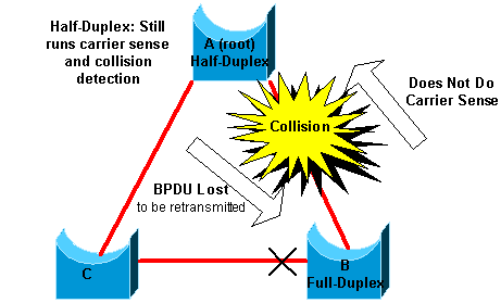
The worst-case scenario is when a bridge that sends BPDUs has the duplex mode set to half-duplex on a port, but the peer port on other end of link has the duplex mode set to full-duplex. In the previous example, the duplex mismatch on the link between bridge A and B can easily lead to a bridging loop. Because bridge B has configuration for full-duplex, it does not perform carrier sense before link access. Bridge B starts to send frames even if bridge A already uses the link. This situation is a problem for A; bridge A detects a collision and runs the backoff algorithm before the bridge attempts another transmission of the frame. If there is enough traffic from B to A, every packet that A sends, which includes the BPDUs, undergoes deferment or collision and eventually gets dropped. From an STP point of view, because bridge B does not receive BPDUs from A any more, bridge B has lost the root bridge. This leads B to unblock the port connected to bridge C, which creates the loop.
Whenever there is a duplex mismatch, this error message can be seen on the switch consoles of Catalyst switches that run Cisco IOS Software:
Cisco IOS Software
%CDP-4-DUPLEX_MISMATCH: duplex mismatch discovered on FastEthernet5/1 (not half duplex), with TBA05071417(Cat6K-B) 4/1 (half duplex).
Check the duplex settings and, if the duplex configuration does not match, set the configuration appropriately.
For more information on how to troubleshoot a duplex mismatch, refer to the document Configure and Verify Ethernet 10/100/1000Mb Half/Full Duplex Auto-Negotiation.
Unidirectional Link
Unidirectional links are a common cause of a bridging loop. On fiber links, a failure that goes without detection often causes unidirectional links. Another cause is a problem with a transceiver. Anything that can lead a link to stay up and provide a one-way communication is very dangerous with regard to STP. This example clarifies:
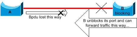
Here, suppose the link between A and B is unidirectional. The link drops traffic from A to B while the link transmits traffic from B to A. Assume that bridge B was blocking before the link became unidirectional. However, a port can only block if it receives BPDUs from a bridge that has a higher priority. Since, in this case, all the BPDUs that come from A are lost, bridge B eventually transitions its port toward A to forwarding state and forwards traffic. This creates a loop. If this failure exists at startup, the STP does not converge correctly. In the case of a duplex mismatch, a reboot helps temporarily; but in this case, a reboot of the bridges has absolutely no effect.
In order to detect the unidirectional links before the creation of the forwarding loop, Cisco designed and implemented the UniDirectional Link Detection (UDLD) protocol. UDLD detects unidirectional conditions on supported Layer 2 links. Configure UDLD aggressive mode on supported point-to-point links where automatic port disablement is required after detection of a unidirectional condition.
For more information on the use of UDLD, refer to the document Configure the UDLD Protocol Feature.
Packet Corruption
Packet corruption can also lead to the same kind of failure. If a link has a high rate of physical errors, you can lose a certain number of consecutive BPDUs. This loss can lead a blocking port to transition to forwarding state. You do not see this case very often because STP default parameters are very conservative. With classic IEEE 802.1D default timers, a blocked port can take approximately 50 seconds from loss of the last superior BPDU to reach the forwarding state: 20 seconds of max age, 15 seconds of listening, and 15 seconds of learning. The successful transmission of a single BPDU breaks the loop. This case commonly occurs with the careless adjustment of STP parameters. An example of an adjustment is max-age reduction.
Duplex mismatch, bad cables, or incorrect cable length can cause packet corruption. Refer to the document Troubleshoot Switch Port and Interface Problems for an explanation of Cisco IOS Software error counter output.
Resource Errors
STP is implemented in software, even on high-end switches that perform most of the switching functions in hardware with specialized application-specific integrated circuits (ASICs). If for any reason there is an over utilization of the CPU of the bridge, resources can be inadequate for the transmission of BPDUs. The STA is generally not processor-intensive and has priority over other processes. The Look for Resource Errors section of this document provides some guidelines on the number of instances of STP that a particular platform can handle.
PortFast Configuration Error
PortFast is a feature that you typically enable only for a port or interface that connects to a host. When the link comes up on this port, the bridge skips the first stages of the STA and directly transitions to the forwarding mode.
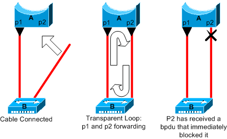
In this example, device A is a bridge with port p1 already forwarding. Port p2 has a PortFast configuration. Device B is a hub. As soon as you plug the second cable into A, port p2 goes to forwarding mode and creates a loop between p1 and p2. This loop stops as soon as p1 or p2 receives a BPDU that puts one of these two ports in blocking mode. But there is a problem with this kind of transient loop. If the looped traffic is very intensive, the bridge can have trouble with the successfully transmission of the BPDU that stops the loop. This problem can delay the convergence considerably or bring down the network in extreme cases.
For more information on the correct use of PortFast on switches that run Cisco IOS Software, refer to the document Using PortFast and Other Commands to Fix Workstation Startup Connectivity Delays.
Even with PortFast configuration, the port or interface still participates in STP. If a switch with a lower bridge priority than that of the current active root bridge attaches to a PortFast-configured port or interface, it can be elected as the root bridge. This change of root bridge can adversely affect the active STP topology and can render the network suboptimal. To prevent this situation, most Catalyst switches that run Cisco IOS Software have a feature with the name BPDU Guard. BPDU Guard disables a PortFast-configured port or interface if the port or interface receives a BPDU.
For more information on the use of the BPDU Guard feature on switches that run Cisco IOS Software, refer to the document Understand the Spanning Tree PortFast BPDU Guard Enhancement.
Awkward STP Parameter Tune and Diameter Issues
An aggressive value for the max-age parameter and the forward delay can lead to a very unstable STP topology. In such cases, the loss of some BPDUs can cause a loop to appear. Another issue that is not well known relates to the diameter of the bridge network. The conservative default values for the STP timers impose a maximum network diameter of seven. This maximum network diameter restricts how far away from each other bridges in the network can be. In this case, two distinct bridges cannot be more than seven hops away from each other. Part of this restriction comes from the age field that BPDUs carry.
When a BPDU propagates from the root bridge toward the leaves of the tree, the age field increments each time the BPDU goes though a bridge. Eventually, the bridge discards the BPDU when the age field goes beyond maximum age. If the root is too far away from some bridges of the network, this issue can occur. This issue affects convergence of the spanning tree.
Take special care if you plan to change STP timers from the default value. There is danger if you try to achieve faster reconvergence in this way. An STP timer change has an impact on the diameter of the network and the stability of the STP. You can change the bridge priority to select the root bridge, and change the port cost or priority parameter to control redundancy and load balancing.
Cisco Catalyst software provides you with macros that finely tune the most important STP parameters for you:
- The spanning-tree vlan number root { primary | secondary } command decreases the bridge priority so that it becomes root (or alternate root). An additional option is available for this command that results in tuning of the STP timers by specifying the diameter of your network. Even when correctly done, timer tuning does not significantly improve the convergence time and introduces some instability risks in the network. Also, this kind of tuning has to be updated each time a device is added into the network. Keep the conservative default values, which are familiar to network engineers.
-
The spanning-tree uplinkfast command for Cisco IOS Software increases the switch priority so that the switch does not become the root bridge. The command reduces STP convergence time after a direct uplink failure. Use this legacy feature on an access-layer switch with redundant uplinks to the distribution layer when the platform and STP mode support it. Refer to the document Understanding and Configuring the Cisco UplinkFast Feature.
-
The spanning-tree backbonefast command for Cisco IOS Software can reduce the STP convergence time of the switch in the event of an indirect link failure. BackboneFast is a Cisco proprietary feature. Refer to the document Understand and Configure Backbone Fast on Catalyst Switches.
For more information on STP timers and the rules to tune them when absolutely necessary, refer to the document Understand and Tune Spanning Tree Protocol Timers.
Software Errors
As mentioned in the Introduction, the STP is one of the first features that was implemented in Cisco products. You can expect this feature to be very stable. Only interaction with newer features, such as EtherChannel, has caused STP to fail in some very specific cases that have now been addressed. A number of different factors can cause a software bug and can have a number of different effects. There is no way to adequately describe the issues that a bug can introduce. The most dangerous situation that arises from software errors is if you ignore some BPDUs or you have a blocking port transition to forwarding.
Troubleshoot a Failure
Unfortunately, there is no systematic procedure to troubleshoot an STP issue. However, this section sums up some of the actions that are available to you. Most of the steps in this section apply to the troubleshooting of bridging loops in general. You can use a more conventional approach to identify other failures of the STP that lead to a loss of connectivity. For example, you can explore the path that the traffic that experiences a problem takes.
If you have the output of a show tech-support command from your Cisco device, you can use Cisco CLI Analyzer.
Note: Only registered Cisco users have access to internal Cisco tools and information.
Use the Diagram of the Network
Before you troubleshoot a bridging loop, you need to know these items, at minimum:
-
The topology of the bridge network
-
The location of the root bridge
-
The location of the blocked ports and the redundant links
This knowledge is essential for at least these two reasons:
-
In order to know what to fix in the network, you need to know how the network looks when it works correctly.
-
Most of the steps to troubleshoot simply use show commands to try to identify error conditions. Knowledge of the network helps you focus on the critical ports on the key devices.
Identify a Bridging Loop
It used to be that a broadcast storm could have a disastrous effect on the network. Today, with high-speed links and devices that provide switching at the hardware level, it is not likely that a single host, for example, a server, brings down a network through broadcasts. The best way to identify a bridging loop is to capture the traffic on a saturated link and check that you see similar packets multiple times. Realistically, however, if all users in a certain bridge domain have connectivity issues at the same time, you can already suspect a bridging loop.
Check the port utilization on your devices and look for abnormal values. Refer to the Check Port Utilization section of this document.
Restore Connectivity Quickly and Be Ready for Another Time
Disable Ports to Break the Loop
Bridging loops have extremely severe consequences on a bridge network. Administrators generally do not have time to look for the cause of the loop and prefer to restore connectivity as soon as possible. In order to stop an active loop, use console or out-of-band access to disable one suspected redundant path at a time, and verify connectivity after each change. Avoid disabling links that provide the only management or forwarding path to a network segment. If you can identify a part of the network that is affected most, begin to disable ports in this area. Or, if possible, initially disable ports that can be blocking. Each time you disable a port, check to see if you have restored connectivity in the network. By identifying which disabled port stops the loop, you also identify the redundant path where this port is located. If this port has been blocking, you have probably found the link on which the failure appeared.
Log STP Events on Devices That Host Blocked Ports
If you cannot precisely identify the source of the problem, or if the problem is transient, enable the logging of STP events on the bridges and switches of the network that experiences the failure. If you want to limit the number of devices to configure, at least enable this logging on devices that host blocked ports; the transition of a blocked port is what creates a loop.

Caution: Debug commands can add control-plane load during a bridging loop. Run them only with console or out-of-band access, monitor CPU utilization, and disable debugging after data collection.
-
Run the debug spanning-tree events EXEC command to enable STP event debugging. Configure logging buffered to capture the messages in the logging buffer.
You can also try to send the debug output to a syslog device. Unfortunately, when a bridging loop occurs, you seldom maintain connectivity to a syslog server.
Check Ports
The critical ports to investigate first are the blocking ports. This section provides a list of what to look for on the different ports, with a quick description of the commands to issue for switches that run Cisco IOS Software.
Check That Blocked Ports Receive BPDUs
Especially on blocked ports and root ports, check that you receive BPDUs periodically. Several issues can lead to a port failure to receive packets or BPDUs.
-
Cisco IOS Software-In Cisco IOS Software Release 12.0 or later, output of the show spanning-tree vlan <vlan-id> detail command has a BPDU field. The field shows you the number of BPDUs received for each interface. Issue the command an additional one or two times to determine if the device receives BPDUs. Another option is to enable STP debug with the debug spanning-tree bpdu command to verify the receipt of BPDUs.
Check for a Duplex Mismatch
To look for a duplex mismatch, you must check each side of the point-to-point link.
-
Cisco IOS Software-Issue the
show interfaces [interface-number] statuscommand to check the speed and duplex status of the specific port.
Check Port Utilization
An interface with traffic overload can fail to transmit vital BPDUs. A link overload also indicates a possible bridging loop.
-
Cisco IOS Software-Use the command
show interfacesto determine the utilization on an interface. Several fields help you with this determination, such as load and packets input/output. Refer to the document Troubleshoot Switch Port and Interface Problems for an explanation of theshow interfacescommand output.
Check Packet Corruption
-
Cisco IOS Software-Look for error increments in the input errors counter of the show interfaces command. The error counters include runts, giants, no buffer, CRC, frame, overrun, and ignored counts.
Refer to the document Troubleshoot Switch Port and Interface Problems for an explanation of the
show interfaces command output.
Look for Resource Errors
A high CPU utilization can be dangerous for a system that runs the STA. Use this method to check that the CPU resource is adequate for a device:
-
Cisco IOS Software-Issue the show processes cpu command. Check that the CPU utilization is not too high.
There is a limitation on the number of different instances of STP that a Supervisor Engine can handle. Ensure that the total number of logical ports across all instances of STP for different VLANs does not exceed the maximum number supported for each Supervisor Engine type and memory configuration.
Issue the show spanning-tree summary totals command for switches, this command display the number of logical ports or interfaces per VLAN in the STP Active column. The total appears at the bottom of this column. The total represents the sum of all logical ports across all instances of STP for the different VLANs. Make sure that this number does not exceed the maximum number supported for each Supervisor Engine type.
(number of non-ATM trunks * number of active Vlans on that trunk)
+ 2*(number of ATM trunks * number of active Vlans on that trunk)
+ number of non-trunking ports
For a summary of the restrictions for STP that apply to Catalyst switches, refer to these documents:
| Platform | Cisco IOS Software STP Restrictions |
|---|---|
| Catalyst 6500/6000 Supervisor Engine 720 | Release Notes for Cisco IOS Release 12.2SXF and Rebuilds |
| Catalyst 4500/4000 | Release Notes for the Catalyst 4500 Series Switch, Cisco IOS, 12.1EW |
| Catalyst 3750 | Catalyst 3750 Switch Software Configuration Guide, Rel. 12.1(19)EA1 |
Useful Commands
Cisco IOS Software Commands
-
show interfaces -
show spanning-tree -
show processes cpu -
debug spanning-tree -
logging buffered
Design STP for Trouble Avoidance
Know Where the Root Is
Very often, information about the location of root is not available at troubleshooting time. Do not leave the STP to decide which bridge is root. For each VLAN, you can usually identify which switch can best serve as root. This depends on the design of the network. Generally, choose a powerful bridge in the middle of the network. If you put the root bridge in the center of the network with direct connection to the servers and routers, you generally reduce the average distance from the clients to the servers and routers.
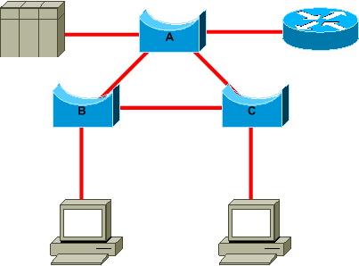
This diagram shows:
-
If bridge B is root, link A to C is blocked on bridge A or bridge C. In this case, hosts that connect to switch B can access the server and the router in two hops. Hosts that connect to bridge C can access the server and the router in three hops. The average distance is two and one-half hops.
-
If bridge A is root, the router and the server are reachable in two hops for both hosts that connect on B and C. The average distance is now two hops.
The logic behind this simple example transfers to more complex topologies.
Know Where Redundancy Is
Plan the organization of your redundant links. Forget about the plug-and-play feature of the STP. Tune the STP cost parameter to decide which ports block. This tuning is usually not necessary if you have a hierarchical design and a root bridge in a good location.
Knowledge of the location of redundant links helps you identify an accidental bridging loop and the cause. Also, knowledge of the location of blocked ports allows you to determine the location of the error.
Minimize the Number of Blocked Ports
The only critical action that STP takes is the blocking of the ports. A single blocking port that mistakenly transitions to forwarding can melt down a large part of the network. A good way to limit the risk inherent in the use of the STP is to reduce the number of blocked ports as much as possible.
Prune VLANs That You Do Not Use
Avoid unnecessary independent Layer 2 paths between two switching nodes. Bundle parallel links into an EtherChannel when the design and platform support it:
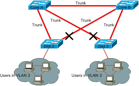
Distribution switches are dual-attached to two core switches. Users that connect on distribution switches are only in a subset of the VLANs available in the network. In this example, users that connect on Dist 2 are all in VLAN 2; Dist 3 only connects users in VLAN 3. By default, trunks carry all the VLANs defined in the VLAN Trunk Protocol (VTP) domain. Only Dist 2 receives unnecessary broadcast and multicast traffic for VLAN 3, but it is also blocking one of its ports for VLAN 3. The result is three redundant paths between Core A and Core B. This redundancy results in more blocked ports and a higher likelihood of a loop.
VTP pruning reduces unnecessary flooded traffic for eligible VLANs, but explicit trunk allowed-VLAN configuration provides deterministic VLAN placement. Do not treat VTP pruning as a replacement for removing unused VLANs from trunk allowed lists.
In this example, only an access VLAN is used to connect the distribution switches to the core:
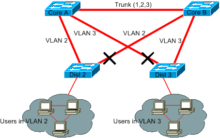
In this design, only one port is blocked per VLAN. Also, with this design, you can remove all redundant links in just one step if you shut down Core A or Core B.
Use Layer 3 Switching
Layer 3 switching means routing approximately at the speed of switching. A router performs two main functions:
-
A router builds a forwarding table. The router generally exchanges information with peers by way of routing protocols.
-
A router receives packets and forwards them to the correct interface based on the destination address.
High-end Cisco Layer 3 switches are able to perform this function, at the same speed as the Layer 2 switching function. If you introduce a routing hop and create an additional segmentation of the network, there is no speed penalty. This diagram uses the example in the section Prune VLANs That You Do Not Use as a basis:
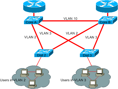
Core A and Core B are now some Layer 3 switches. VLAN 2 and VLAN 3 are no longer bridged between Core A and Core B, so an STP loop cannot traverse that routed boundary. Layer 2 loops remain possible within each bridged VLAN.
-
Redundancy is still present, with a reliance on Layer 3 routing protocols. The design uses Layer 3 routing for path redundancy. Convergence time depends on the routing protocol, failure-detection mechanism, timers, topology, and platform.
-
There is no longer any single port that the STP blocks. Therefore, there is no potential for a bridging loop.
-
There is no speed penalty, as to leave the VLAN by Layer 3 switching is as fast as bridging inside the VLAN.
There is a single drawback with this design. Migration to this kind of design generally implies a rework of the addressing scheme.
Keep STP Even If It Is Unnecessary
Even if you have succeeded with the removal of all the blocked ports from your network and you do not have any physical redundancy, do not disable STP. STP is generally not very processor-intensive; packet switching does not involve the CPU in most Cisco switches. Also, the few BPDUs that are sent on each link do not significantly reduce the available bandwidth. However, a bridge network without STP can melt down in a fraction of a second if an operator makes an error on a patch panel, for example. Generally, disabling the STP in a bridge network is not worth the risk.
Keep Traffic off the Administrative VLAN and Do Not Have a Single VLAN Span the Entire Network
A Cisco switch typically has a single IP address that binds to a VLAN, known as the administrative VLAN. In this VLAN, the switch behaves like a generic IP host. Broadcast, multicast, and control-plane traffic in the administrative VLAN can consume CPU resources, depending on the traffic type, platform, software release, and control-plane configuration. A high rate of broadcast or multicast traffic on the administrative VLAN can adversely impact the CPU and the CPU ability to process vital BPDUs. Therefore, keep user traffic off the administrative VLAN.
In older releases, there was no way to remove VLAN 1 from a trunk in Cisco implementation. VLAN 1 generally serves as an administrative VLAN, where all switches are accessible in the same IP subnet. Though useful, this setup can be dangerous because a bridging loop on VLAN 1 affects all trunks, which can bring down the whole network. Of course, the same problem exists no matter which VLAN you use. Try to segment the bridging domains with use of high-speed Layer 3 switches.
As of Cisco IOS Software Release 12.1(11b)E, you can remove VLAN 1 from trunks. VLAN 1 remains present, but it can improve security and reduce unnecessary Layer-2 traffic.
Related Information
Revision History
| Revision | Publish Date | Comments |
|---|---|---|
5.0 |
09-Sep-2026
|
Recertification, formatting and fixed links. |
3.0 |
09-May-2024
|
Recertification |
2.0 |
10-Jan-2023
|
Article was created internally to match the article currently on Cisco.com.
Images converted to .png format.
Updated Intro, Alt Text, gerunds, etc. |
1.0 |
05-Dec-2017
|
Initial Release |

 Feedback
Contact Cisco
- Open a Support Case

- (Requires a Cisco Service Contract)