-
Cisco MDS 9000 Family Fabric Manager Configuration Guide, Release 3.4(1a)
-
Index
-
New and Changed Information
-
Preface
- Getting Started
- Installation and Switch Management
- Switch Configuration
-
Fabric Configuration
-
Configuring and Managing VSANs
-
SAN Device Virtualization
-
Creating Dynamic VSANs
-
Configuring Inter-VSAN Routing
-
Configuring and Managing Zones
-
Distributing Device Alias Services
-
Configuring Fibre Channel Routing Services and Protocols
-
Dense Wavelength Division Multiplexing
-
Managing FLOGI, Name Server, FDMI, and RSCN Databases
-
Discovering SCSI Targets
-
Configuring FICON
-
Advanced Features and Concepts
-
-
Security
-
Configuring FIPS
-
Configuring Users and Common Roles
-
Configuring SNMP
-
Configuring RADIUS and TACACS+
-
Configuring IPv4 Access Control Lists
-
Configuring Certificate Authorities and Digital Certificates
-
Configuring IPsec Network Security
-
Configuring FC-SP and DHCHAP
-
Configuring Port Security
-
Configuring Fabric Binding
-
- IP Services
- Intelligent Storage Services
- Network and Switch Monitoring
- Traffic Management
- Troubleshooting
-
Launching Fabric Manager in Cisco SAN-OS Releases Prior to 3.2(1)
-
Cisco Fabric Manager Unsupported Feature List
-
Interface Nonoperational Reason Codes
-
Managing Cisco FabricWare
-
Configuration Limits for Cisco MDS SAN-OS Release 3.1(x) and 3.2(x)
-
 Feedback
Table Of Contents
Monitoring Network Traffic Using SPAN
Allowed Source Interface Types
Guidelines to Configure VSANs as a Source
Guidelines to Specifying Filters
Monitoring Traffic Using Fibre Channel Analyzers
Configuring Fibre Channel Analyzers Using SPAN
Single SD Port to Monitor Traffic
Monitoring Network Traffic Using SPAN
This chapter describes the Switched Port Analyzer (SPAN) features provided in switches in the Cisco MDS 9000 Family. It includes the following sections:
•
Monitoring Traffic Using Fibre Channel Analyzers
About SPAN
The SPAN feature is specific to switches in the Cisco MDS 9000 Family. It monitors network traffic through a Fibre Channel interface. Traffic through any Fibre Channel interface can be replicated to a special port called the SPAN destination port (SD port). Any Fibre Channel port in a switch can be configured as an SD port. Once an interface is in SD port mode, it cannot be used for normal data traffic. You can attach a Fibre Channel Analyzer to the SD port to monitor SPAN traffic (see the"Configuring the Cisco Fabric Analyzer" section on page 68-20.
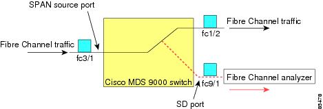
SD ports do not receive frames, they merely transmit a copy of the SPAN source traffic. The SPAN feature is non-intrusive and does not affect switching of network traffic for any SPAN source ports (see Figure 52-1).
Figure 52-1 SPAN Transmission
SPAN Sources
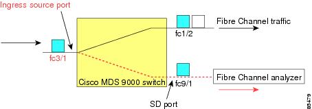
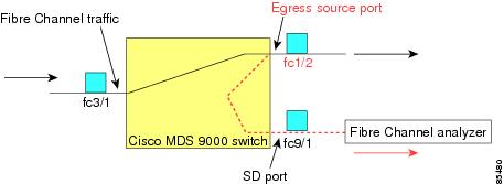
SPAN sources refer to the interfaces from which traffic can be monitored. You can also specify VSAN as a SPAN source, in which case, all supported interfaces in the specified VSAN are included as SPAN sources. You can choose the SPAN traffic in the ingress direction, the egress direction, or both directions for any source interface:
•
Figure 52-2 SPAN Traffic from the Ingress Direction
•
Figure 52-3 SPAN Traffic from Egress Direction
IPS Source Ports
SPAN capabilities are available on the IP Storage Services (IPS) module. The SPAN feature is only implemented on the FCIP and iSCSI virtual Fibre Channel port interfaces, not the physical Gigabit Ethernet ports. You can configure SPAN for ingress traffic, egress traffic, or traffic in both directions for all eight iSCSI and 24 FCIP interfaces that are available in the IPS module.
Note
Allowed Source Interface Types
The SPAN feature is available for the following interface types:
•
•
–
–
•
–
–
•
–
–
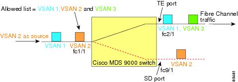
VSAN as a Source
When a VSAN as a source is specified, then all physical ports and PortChannels in that VSAN are included as SPAN sources. A TE port is included only when the port VSAN of the TE port matches the source VSAN. A TE port is excluded even if the configured allowed VSAN list may have the source VSAN, but the port VSAN is different.
You cannot configure source interfaces (physical interfaces, PortChannels, or sup-fc interfaces) and source VSANs in the same SPAN session.
Guidelines to Configure VSANs as a Source
The following guidelines apply when configuring VSANs as a source:
•
•
•
•
–
–
–
Figure 52-4 VSAN as a Source
For this configuration, the following apply:
–
–
See the "Configuring an Allowed-Active List of VSANs" section on page 24-7 or the "About Port VSAN Membership" section on page 1-8.
SPAN Sessions
Each SPAN session represents an association of one destination with a set of source(s) along with various other parameters that you specify to monitor the network traffic. One destination can be used by one or more SPAN sessions. You can configure up to 16 SPAN sessions in a switch. Each session can have several source ports and one destination port.
To activate any SPAN session, at least one source and the SD port must be up and functioning. Otherwise, traffic is not directed to the SD port.
Tip
You can temporarily deactivate (suspend) any SPAN session. The traffic monitoring is stopped during this time.
Specifying Filters
You can perform VSAN-based filtering to selectively monitor network traffic on specified VSANs. You can apply this VSAN filter to all sources in a session (see Figure 52-4). Only VSANs present in the filter are spanned.
You can specify session VSAN filters that are applied to all sources in the specified session. These filters are bidirectional and apply to all sources configured in the session.
Guidelines to Specifying Filters
The following guidelines apply to SPAN filters:
•
•
•
SD Port Characteristics
An SD port has the following characteristics:
•
•
•
•
•
•
•
•
•
•
Note
Guidelines to Configure SPAN
The following guidelines apply for SPAN configurations:
•
•
•
•
•
Configuring SPAN
To monitor network traffic using SD ports, follow these steps:
Step 1
Step 2
Step 3
Configuring SPAN
To configure an SD port for SPAN monitoring using Device Manager, follow these steps:
Step 1
You see the general port configuration dialog.
Step 2
Step 3
Step 4
Caution
Caution
Caution
Creating SPAN Sessions
To create SPAN sessions using Device Manager, follow these steps:
Step 1
Step 2
Step 3
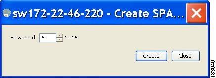
You see the Create SPAN Sessions dialog box shown in Figure 52-5.
Figure 52-5 Create SPAN Sessions Dialog Box
Step 4
Step 5
Step 6
Step 7
Step 8
Step 9
Step 10
Editing SPAN Sources
To edit a SPAN source using Device Manager, follow these steps:
Step 1
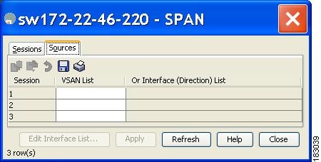
You see the SPAN dialog box.
Step 2
You see the dialog box shown in Figure 52-6.
Figure 52-6 SPAN Sources Tab
Step 3
Step 4
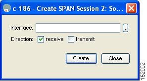
You see the Source Interfaces dialog box.
Step 5
You see the Source Interfaces Interface Sources dialog box shown in Figure 52-7.
Figure 52-7 Source Interfaces Interface Sources Dialog Box
Step 6
Step 7
Step 8
Step 9
Step 10
Deleting SPAN Sessions
To delete a SPAN session using Device Manager, follow these steps:
Step 1
You see the SPAN dialog box.
Step 2
Step 3
Step 4
The SPAN session is deleted.
Step 5
SPAN Conversion Behavior
SPAN features (configured in any prior release) are converted as follows:
•
For example, before Cisco MDS SAN-OS Release 1.0(4):
Session 1 (active)Destination is fc1/9No session filters configuredIngress (rx) sources arevsans 10-11fc1/3,Egress (tx) sources arefc1/3,Once upgraded to Cisco MDS SAN-OS Release 1.1(1):
Session 1 (active)Destination is fc1/9No session filters configuredIngress (rx) sources arefc1/3,Egress (tx) sources arefc1/3,Session 1 had both source interfaces and source VSANs before the upgrade. After the upgrade, the source VSANs were removed (rule 1).
•
For example, before Cisco MDS SAN-OS Release 1.0(4):
Session 2 (active)Destination is fc1/9No session filters configuredIngress (rx) sources arevsans 12fc1/6 (vsan 1-20),Egress (tx) sources arefc1/6 (vsan 1-20),Once upgraded to Cisco MDS SAN-OS Release 1.1(1):
Session 2 (inactive as no active sources)Destination is fc1/9No session filters configuredNo ingress (rx) sourcesNo egress (tx) sources
Note
Session 2 had a source VSAN 12 and a source interface fc1/6 with VSAN filters specified in Cisco MDS SAN-OS Release 1.0(4). When upgraded to Cisco MDS SAN-OS Release 1.1(1) the following changes are made:
–
–
Monitoring Traffic Using Fibre Channel Analyzers
You can use SPAN to monitor traffic on an interface without any traffic disruption. This feature is specially useful in troubleshooting scenarios where traffic disruption changes the problem environment and makes it difficult to reproduce the problem.
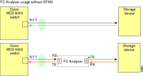
Without SPAN
You can monitor traffic using interface fc1/1 in a Cisco MDS 9000 Family switch that is connected to another switch or host. You need to physically connect a Fibre Channel analyzer between the switch and the storage device to analyze the traffic through interface fc1/1 as shown in Figure 52-8.
Figure 52-8 Fibre Channel Analyzer Usage Without SPAN
This type of connection has the following limitations:
•
•
•
With SPAN
Using SPAN you can capture the same traffic scenario shown in Figure 52-8 without any traffic disruption. The Fibre Channel analyzer uses the ingress (Rx) link at port 1 to capture all the frames going out of the interface fc1/1. It uses the ingress link at port 2 to capture all the ingress traffic on interface fc1/1.
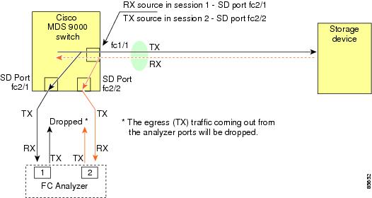
Using SPAN you can monitor ingress traffic on fc1/1 at SD port fc2/2 and egress traffic on SD port fc2/1. This traffic is seamlessly captured by the FC analyzer as shown in Figure 52-9.
Figure 52-9 Fibre Channel Analyzer Using SPAN
Configuring Fibre Channel Analyzers Using SPAN
To configure Fibre Channel Analyzers using SPAN for the example in Figure 52-9, follow these steps:
Step 1
Step 2
Step 3
Step 4
Single SD Port to Monitor Traffic
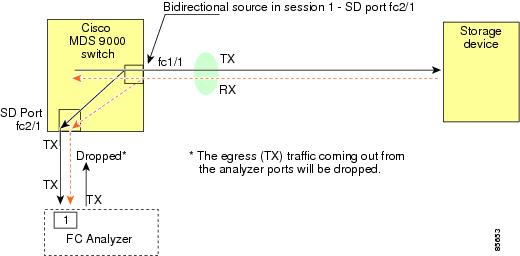
You do not need to use two SD ports to monitor bidirectional traffic on any interface as shown in Figure 52-9. You can use one SD port and one FC analyzer port by monitoring traffic on the interface at the same SD port fc2/1.
Figure 52-10 shows a SPAN setup where one session with destination port fc2/1 and source interface fc1/1 is used to capture traffic in both ingress and egress directions. This setup is more advantageous and cost effective than the setup shown in Figure 52-9—it uses one SD port and one port on the analyzer, instead of using a full, two-port analyzer.
Figure 52-10 Fibre Channel Analyzer Using a Single SD Port
To use this setup, the analyzer should have the capability of distinguishing ingress and egress traffic for all captured frames.
Default SPAN Settings
Table 52-1 lists the default settings for SPAN parameters.