Cisco MDS 9000 Family Fabric Manager Configuration Guide, Release 3.4(1a)
Software Images

Table Of Contents

Software Images

About Software Images

Dependent Factors for Software Installation

Selecting the Correct Software Images for Cisco MDS 9100 Series Switches

Selecting the Correct Software Images for Cisco MDS 9200 Series Switches

Selecting the Correct Software Images for Cisco MDS 9500 Family Switches

Essential Upgrade Prerequisites

Software Upgrade Methods

Determining Software Compatibility

Automated Upgrades

Benefits of Using the Software Install Wizard

Recognizing Failure Cases

Using the Software Install Wizard

Upgrading Services Modules

Non-Disruptive Upgrades on Fabric and Modular Switches

Preparing for a Non-Disruptive Upgrade on Fabric and Modular Switches

Performing a Non-Disruptive Upgrade on a Fabric Switch

Maintaining Supervisor Modules

Replacing Supervisor Modules

Standby Supervisor Module Boot Variable Version

Standby Supervisor Module Bootflash Memory

Standby Supervisor Module Boot Alert

Installing Generation 2 Modules in Generation 1 Chassis

Replacing Modules

Default Settings


Software Images


This chapter describes how to install and upgrade Cisco MDS SAN-OS software images. It includes the following sections:

About Software Images

Essential Upgrade Prerequisites

Software Upgrade Methods

Automated Upgrades

Using the Software Install Wizard

Non-Disruptive Upgrades on Fabric and Modular Switches

Maintaining Supervisor Modules

Installing Generation 2 Modules in Generation 1 Chassis

Replacing Modules

Default Settings

About Software Images

Each switch is shipped with a Cisco MDS SAN-OS operating system for Cisco MDS 9000 Family switches. The Cisco MDS SAN-OS consists of two images—the kickstart image and the system image. To upgrade the switch to a new image, you must specify the variables that direct the switch to the images.

To select the kickstart image, use the KICKSTART variable.

To select the system image, use the SYSTEM variable.

The images and variables are important factors in any install procedure. You must specify the variable and the image to upgrade your switch. Both images are not always required for each install.


Note Unless explicitly stated, the software install procedures in this chapter apply to any switch in the Cisco MDS 9000 Family.


Dependent Factors for Software Installation

The software image install procedure is dependent on the following factors:

Software images—The kickstart and system image files reside in directories or folders that can be accessed from the Cisco MDS 9000 Family switch prompt.

Image version—Each image file has a version.

Flash disks on the switch—The bootflash: resides on the supervisor module and the CompactFlash disk is inserted into the slot0: device.

Supervisor modules—There are single or dual supervisor modules.

Selecting the Correct Software Images for Cisco MDS 9100 Series Switches

The Supervisor-1 and Supervisor-2 modules supported by Cisco MDS 9100 Series switches require different system and kicstart images. You can determine which images to use on your switch by the naming conventions shown in Table 15-1.

Table 15-1 Supervisor Module Software Image Naming Conventions for MDS 9100 Series

Cisco MDS 9100 Series Switch Type
Supervisor Module Type
Naming Convention

9124, 9134, Cisco Fabric Switch for HP c-Class BladeSystem, Cisco Fabric Switch for IBM BladeCenter

Supervisor-2 module

Filename begins with m9100-s2ek9

9120 or 9140

Supervisor-1 module

Filename begins with m9100-s1ek9


Selecting the Correct Software Images for Cisco MDS 9200 Series Switches

The Supervisor-1 and Supervisor-2 modules supported by Cisco MDS 9200 Series switches require different system and kicstart images. You can determine which images to use on your switch by the naming conventions shown in Table 15-2.

Table 15-2 Supervisor Module Software Image Naming Conventions for MDS 9200 Series

Cisco MDS 9200 Series Switch Type
Supervisor Module Type
Naming Convention

9222i

Supervisor-2 module

Filename begins with m9200-s2ek9

9216, 9216A or 9216i

Supervisor-1 module

Filename begins with m9200-s1ek9


Selecting the Correct Software Images for Cisco MDS 9500 Family Switches

The Supervisor-1 and Supervisor-2 modules supported by Cisco MDS 9500 Family switches require different system and kickstart images. You can determine which images to use on your switch by the naming conventions shown in Table 15-3.

Table 15-3 Supervisor Module Software Image Naming Conventions for MDS 9500 Series

Cisco MDS 9500 Series Switch Type
Supervisor Module Type
Naming Convention

9513

Supervisor-2 module

Filename begins with m9500-sf2ek9

9506 or 9509

Supervisor-1 module

Filename begins with m9500-sf1ek9

Supervisor-2 module

Filename begins with m9500-sf2ek9


Essential Upgrade Prerequisites


Note During a software upgrade to Cisco SAN-OS 3.1(3), the CompactFlash CRC Checksum test runs automatically in the background. All modules that are online are tested and the installation stops if any modules are running with a faulty CompactFlash. When this occurs, the switch can not be upgraded until the situation is corrected. A system message displays the module information and indicates that you must issue the system health cf-crc-check module CLI command to troubleshoot. For complete configuration information about the CompactFlash CRC checksum test feature, refer to the Cisco MDS 9000 Family CLI Configuration Guide. For descriptions of new commands supported by the CompactFlash checksum feature, refer to the Cisco MDS 9000 Family Command Reference.


Before attempting to migrate to any software image version, follow these guidelines:

Customer Service

Before performing any software upgrade, contact your respective customer service representative to review your software upgrade requirements and to provide recommendations based on your current operating environment.


Note If you purchased Cisco support through a Cisco reseller, contact the reseller directly. If you purchased support directly from Cisco Systems, contact Cisco Technical Support at this URL: http://www.cisco.com/warp/public/687/Directory/DirTAC.shtml


Scheduling

Schedule the upgrade when the fabric is stable and steady. Ensure that everyone who has access to the switch or the network is not configuring the switch or the network during this time. All configurations are disallowed at this time.

Space

Verify that sufficient space is available in the location where you are copying the images. This location includes the active and standby supervisor module bootflash: (internal to the switch).

Standby supervisor module bootflash: file system (see Chapter 12, "Initial Configuration").

Internal bootflash: offers approximately 200 MB of user space.

Hardware

Avoid power interruption during any install procedure. These kinds of problems can corrupt the software image.

Connectivity (to retrieve images from remote servers)

Configure the IPv4 address or IPv6 address for the 10/100/1000 BASE-T Ethernet port connection (interface mgmt0).


Note 1000 BASE-T Ethernet is only available on Supervisor-2 modules.


Ensure the switch has a route to the remote server. The switch and the remote server must be in the same subnetwork if you do not have a router to route traffic between subnets.

Images

Ensure that the specified system and kickstart images are compatible with each other.

If the kickstart image is not specified, the switch uses the current running kickstart image.

If you specify a different system image, ensure that it is compatible with the running kickstart image.

Retrieve images in one of two ways:

Local file—images are locally available on the switch.

Network file—images are in a remote location and the user specifies the destination using the remote server parameters and the file name to be used locally.

Terminology

Table 15-4 summarizes terms used in this chapter with specific reference to the install and upgrade process.

Table 15-4 Terms Specific to This Chapter

Term
Definition

bootable

The modules ability to boot or not boot based on image compatibility.

impact

The type of software upgrade mechanism—disruptive or nondisruptive.

install-type

reset

Resets the module.

sw-reset

Resets the module immediately after switchover.

rolling

Upgrades each module in sequence.

copy-only

Updates the software for BIOS, loader, or bootrom.


Tools

Verify connectivity to the remote server by clicking Verify Remote Server in the Software Install Wizard in Fabric Manager.

Ensure that the required space is available for the image files to be copied by using Software Install Wizard to check free disk space.

We recommend the Software Install Wizard in Fabric Manager to upgrade your software. This wizard upgrades all modules in any Cisco MDS 9000 Family switch (see the "Benefits of Using the Software Install Wizard" section).

Run only one installation on a switch at any time.

Do not issue another command while running the installation.

Do the installation on the active supervisor module, not the standby supervisor module.


Note If the switching module(s) are not compatible with the new supervisor module image, some traffic disruption may be noticed in the related modules, depending on your configuration. These modules are identified in the summary when you use the Installation Wizard. You can choose to proceed with the upgrade or end at this point.


Note The Software Install Wizard displays a summary of changes that are made to your configuration.


Note Prior to Cisco SAN-OS Release 3.0, to preserve the FC IDs in your configuration, verify that the persistent FC ID feature is enabled before rebooting. This feature is enabled by default. In earlier releases, the default is disabled. See the "FC IDs" section on page 25-16.


Software Upgrade Methods

You can upgrade software without any disruptions using the Cisco MDS SAN-OS software designed for mission-critical high availability environments. To realize the benefits of nondisruptive upgrades on the Cisco MDS 9500 Directors, we highly recommend that you install dual supervisor modules.

You can upgrade any switch in the Cisco MDS 9000 Family using one of the following methods:

Automatic - you can use the Fabric Manager Software Install Wizard for Cisco MDS SAN-OS switches as described in the "Using the Software Install Wizard" section.

Manual - for information on manual upgrades, see the Cisco MDS 9000 Family CLI Configuration Guide or the Cisco MDS 9020 Switch Configuration Guide and Command Reference.

In some cases, regardless of which process you use, the software upgrades may be disruptive. These exception scenarios can occur under the following conditions:

A single supervisor module system with kickstart or system image changes.

A dual supervisor module system with incompatible system software images.


Note For high availability, you need to connect the ethernet port for both active and standby supervisors to the same network or virtual LAN. The active supervisor owns the one IP address used by these ethernet connections. On a switchover, the newly activated supervisor takes over this IP address.


Determining Software Compatibility

If the running image and the image you want to install are incompatible, the software reports the incompatibility. In some cases, you may decide to proceed with this installation. If the active and the standby supervisor modules run different versions of the image, both images may be HA compatible in some cases and incompatible in others.

Compatibility is established based on the image and configuration:

Image incompatibility—The running image and the image to be installed are not compatible.

Configuration incompatibility—There is a possible incompatibility if certain features in the running image are turned off as they are not supported in the image to be installed. The image to be installed is considered incompatible with the running image if one of the following statements is true:

An incompatible feature is enabled in the image to be installed and it is not available in the running image and may cause the switch to move into an inconsistent state. In this case, the incompatibility is strict.

An incompatible feature is enabled in the image to be installed and it is not available in the running image and does not cause the switch to move into an inconsistent state. In this case, the incompatibility is loose.


Tip The Software Install Wizard compares and presents the results of the compatibility before proceeding with the installation. You can exit if you do not want to proceed with these changes.


Automated Upgrades

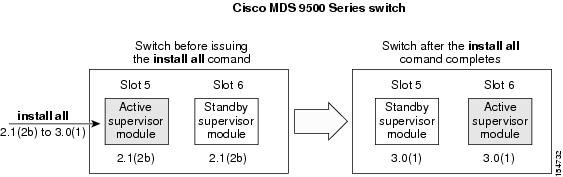
The Software Install Wizard upgrades all modules in any Cisco MDS 9000 Family switch. Figure 15-1 provides an overview of the switch status before and after using Software Install Wizard.

Figure 15-1 The Effect of the Software Install Wizard

The Software Install Wizard automatically verifies if the standby supervisor module is functioning (if present). If it is not functioning, it reloads that module and uses the force download option to force it to function.

Benefits of Using the Software Install Wizard

The Software Install Wizard provides the following benefits:

You can upgrade the entire switch using just one procedurecommand.

You can receive descriptive information on the intended changes to your system before you continue with the installation.

You can upgrade the entire switch using the least disruptive procedure.

You can see the progress of this command on the console, Telnet, and SSH screens:

After a switchover process, you can see the progress from both the supervisor modules.

Before a switchover process, you can only see the progress from the active supervisor module.

The Software Install Wizard automatically checks the image integrity. This includes the running kickstart and system images.

The Software Install Wizard performs a platform validity check to verify that a wrong image is not used—for example, to check if an MDS 9500 Series image is used inadvertently to upgrade an MDS 9200 Series switch.

After issuing the installation, if any step in the sequence fails, the wizard completes the step in progress and ends.

For example, if a switching module fails to be updated for any reason (for example, due to an unstable fabric state), then the command sequence disruptively updates that module and ends. In such cases, you can verify the problem on the affected switching module and upgrade the other switching modules.

Recognizing Failure Cases

The following situations cause the installation to end:

If the standby supervisor module bootflash: file system does not have sufficient space to accept the updated image.

If the specified system and kickstart images are not compatible.

If the fabric or switch is configured while the upgrade is in progress.

If a module is removed while the upgrade is in progress.

If the switch has any power disruption while the upgrade is in progress.

If the entire path for the remote location is not specified accurately.

If images are incompatible after an upgrade. For example, a switching module image may be incompatible with the system image, or a kickstart image may be incompatible with a system image. This is also identified by the Software Install Wizard compatibility check.


Caution If the installation is ended, be sure to verify the state of the switch at every stage and reissue the command after 10 seconds. If you reissue the installation within the 10-second span, it is rejected with an error message indicating that an installation is currently in progress.


Tip All configurations are disallowed while the installation is in progress. However, configurations coming through the CFS applications are allowed and may affect the upgrade procedure.


Using the Software Install Wizard

You can use the Software Install Wizard to install Cisco SAN-OS images on supported switches.


Note The Software Install Wizard supports installation and upgrade for Cisco MDS 9020 Fabric Switch or Cisco FabricWare. For successful installation and upgrade specify the TFTP server address that the Cisco MDS 9020 Fabric Switch should use.


Note Before you use this wizard, be sure the standby supervisor management port is connected.


To use the Software Install Wizard, follow these steps:
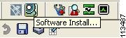

Step 1 Click the Software Install Wizard icon in the toolbar (see Figure 15-2).

Figure 15-2 Software Install Wizard Icon

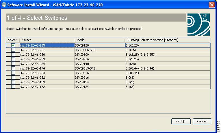
You see the Select Switches dialog box with all switches selected by default.

Figure 15-3 Select Switches Dialog Box

Step 2 Deselect the check box for the switch(es) for which you do not want to install images on. You must have at least one switch selected to proceed (see Figure 15-3).

Step 3 Click Next when finished.

Step 4 Optionally, check the Skip Image Download check box and click Next to use images that are already downloaded (the file is already on the bootflash). Proceed to Step 7.

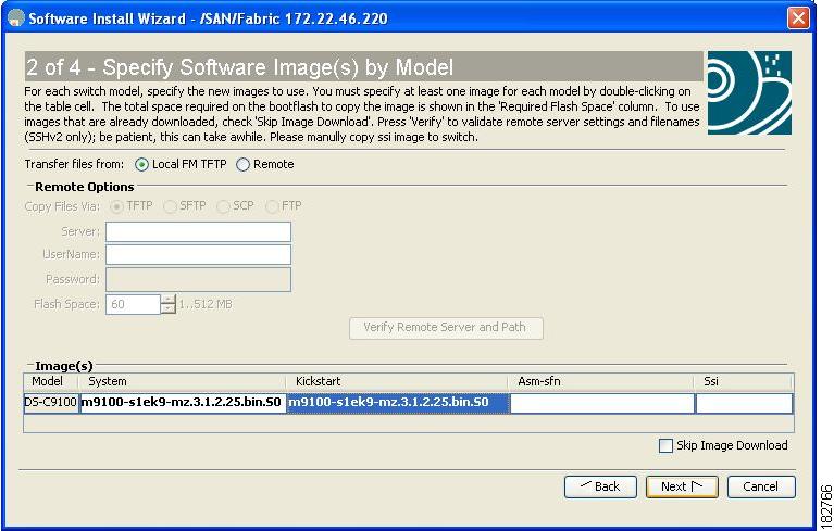
You see the Specify Software Image(s) by Model Dialog Box shown in Figure 15-4.

Figure 15-4 Specify Software Image(s) by Model Dialog Box

Step 5 Click the row under the System, Kickstart, ASM-SFN, or SSI columns to enter image URIs.You must specify at least one image for each switch to proceed.

Step 6 Click Next.

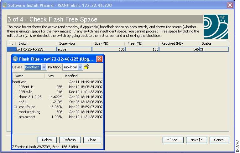
You see the Check Flash Free Space dialog box (see Figure 15-5). This dialog box shows the active (and standby, if applicable) bootflash space on each switch, and shows the status (whether there is enough space for the new images). If any switch has insufficient space, you cannot proceed. Deselect the switch without enough bootflash by going back to the first screen and unchecking the check box for that switch.

Figure 15-5 Check Flash Free Space Dialog Box

Step 7 Click Next.

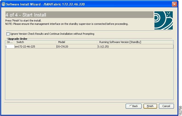
You see the Start Install dialog box shown in Figure 15-6.

Figure 15-6 Start Install Dialog Box


Note There is no limit on the number of switches you can upgrade. However, the upgrade is a serial process; that is, only a single switch is upgraded at a time.


Step 8 Optionally, check the Ignore version check results check box to bypass a version check.


Note The version check provides information about the impact of the upgrade for each module on the switch. It also shows any HA-related incompatibilities that might result. You see a final dialog box at this stage, prompting you to confirm that this check should be performed. We recommend that you do not ignore the version check results.


Caution If Ignore version check results is checked, the upgrade will proceed even if the current switch version is newer than the version you are installing.

Step 9 Click Finish to start the installation.

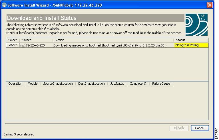
You see the Download and Install Status dialog box shown in Figure 15-7.

Figure 15-7 Download and Install Status Dialog Box


Note On hosts where the TFTP server cannot be started, a warning is displayed. The TFTP server may not start because an existing TFTP server is running or because access to the TFTP port 69 has been denied for security reasons (the default setting on Linux). In these cases, you cannot transfer files from the local host to the switch.


Note Before exiting the session, be sure the upgrade process is complete. The wizard will display a status as it goes along. Check the lower left-hand corner of the wizard for the status message Upgrade Finished. First, the wizard displays the message Success followed a few seconds later by InProgress Polling. Then the wizard displays a second message Success before displaying the final Upgrade Finished.


Upgrading Services Modules

Any Fibre Channel switching module supports nondisruptive upgrades. The14/2-port Multiprotocol Services (MPS-14/2)) module supports nondisruptive upgrades for the Fibre Channel ports. Any software upgrade for the two Gigabit Ethernet ports in this module is disruptive. See Chapter 44, "Configuring IP Storage" for more information on MPS-14/2 modules.


Caution Any software upgrade for the Caching Services Module (CSM) and the IP Storage (IPS) services modules is disruptive.

CSMs and IPS modules use a rolling upgrade install mechanism to guarantee a stable state for each module in the switch:

Each IPS module in a switch requires a 5-minute delay before the next IPS module is upgraded. See Chapter 44, "Configuring IP Storage" for more information on IPS modules.

Each CSM module requires a 30-minute delay before the next CSM module is upgraded. See the Cisco MDS 9000 Family SAN Volume Controller Configuration Guide for more information on CSMs.

Non-Disruptive Upgrades on Fabric and Modular Switches

This section describes how to perform non-disruptive upgrades on the following Cisco Fabric Switches:

Cisco MDS 9124 Multilayer Fabric Switch

Cisco MDS 9134 Multilayer Fabric Switch

Cisco MDS 9222i Multiservice Modular Switch

Cisco Fabric Switch for HP c-Class BladeSystem

Cisco Fabric Switch for IBM BladeCenter

This section includes the following topics:

Preparing for a Non-Disruptive Upgrade on Fabric and Modular Switches

Performing a Non-Disruptive Upgrade on a Fabric Switch

Preparing for a Non-Disruptive Upgrade on Fabric and Modular Switches

You can upgrade software on the following without any disruptions using the Software Install Wizard for the system software images.

Cisco MDS 9124 Multilayer Fabric Switch

Cisco MDS 9134 Multlayer Fabric Switch

Cisco MDS 9222i Multiservice Modular Switch

Cisco Fabric Switch for HP c-Class BladeSystem

Cisco Fabric Switch for IBM BladeCenter

When completed, the supervisor kickstart image, supervisor system image, the linecard image and the system bios are all updated.

Non-disruptive upgrades on these fabric switches take down the control plane for not more than 80 seconds. In some cases, when the upgrade has progressed past the point at which it cannot be stopped gracefully, or if a failure occurs, the software upgrade may be disruptive.


Note During the upgrade the control plane is down, but the data plane remains up. So new devices will be unable to log in to the fabric via the control plane, but existing devices will not experience any disruption of traffic via the data plane.


Before attempting to upgrade any software images on these fabric switches, follow these guidelines:

During the upgrade, the fabric must be stable. None of the following configuration activities are allowed:

zoning changes

telnet sessions

schedule changes

switch cabling

addition or removal of physical devices

Configure the FSPF timers to the default value of 20 seconds.

If there are any CFS commits pending in the fabric, the upgrade is aborted.

If there is a zone server merge in progress, the upgrade is aborted.

Check whether there is sufficient space available in the system to load the new images using the Software Install Wizard. At this point you need to either abort the upgrade or proceed with a disruptive upgrade.

On the Cisco MDS 18/4-port multiservice module, upgrades of the 4 Gigabit Ethernet ports for the hybrid Supervisor 18/4 line card will be disruptive.

Performing a Non-Disruptive Upgrade on a Fabric Switch

Cisco MDS 9124 Multilayer Fabric Switch

Cisco MDS 9134 Multlayer Fabric Switch

Cisco MDS 9222i Multiservice Modular Switch

Cisco Fabric Switch for HP c-Class BladeSystem

Cisco Fabric Switch for IBM BladeCenter

You can use the Software Install Wizard to perform non-disruptive upgrades on Cisco MDS 9124 Fabric Switches. See "Using the Software Install Wizard" section for more information on using the Sofware Install Wizard.


Caution It is recommended that you enable port-fast on the ethernet interface of the catalyst to which the management interface of the fabric switch is connected. This is to avoid spanning-tree convergence time on the catalyst and packets from the fabric switch are forwarded immediately during the non-disruptive upgrade.


Note When selecting images during the upgrade, ASM-SFN and SSI are not supported on the Cisco MDS 9124 Switch and the Cisco MDS 9134 Multilayer Fabric Switch.


Maintaining Supervisor Modules

This section includes general information about replacing and using supervisor modules effectively.

This section includes the following topics:

Replacing Supervisor Modules

Standby Supervisor Module Boot Variable Version

Standby Supervisor Module Bootflash Memory

Standby Supervisor Module Boot Alert

Replacing Supervisor Modules

To avoid packet loss when removing a supervisor module from a Cisco MDS 9500 Series Director, take the supervisor modules out of service before removing the supervisor module.


Note You must remove and reinsert or replace the supervisor module to bring it into service.


Standby Supervisor Module Boot Variable Version

If the standby supervisor module boot variable images are not the same version as those running on the active supervisor module, the software forces the standby supervisor module to run the same version as the active supervisor module.

If you specifically set the boot variables of the standby supervisor module to a different version and reboot the standby supervisor module, the standby supervisor module will only load the specified boot variable if the same version is also running on the active supervisor module. At this point, the standby supervisor module is not running the images set in the boot variables.

Standby Supervisor Module Bootflash Memory

When updating software images on the standby supervisor module, verify that there is enough space available for the image . It is a good practice to remove older versions of Cisco MDS SAN-OS images and kickstart images.

To verify the space on the standby supervisor using Device Manager, follow these steps:


Step 1 Click Admin > Flash Files.

Step 2 Select the standby supervisor from the Partition drop-down list.

At the bottom of the Flash Files dialog box, you see the space used and free space.


Standby Supervisor Module Boot Alert

If a standby supervisor module fails to boot, the active supervisor module detects that condition and generates a Call Home event and a system message and reboots the standby supervisor module approximately 3 to 6 minutes after the standby supervisor module moves to the loader> prompt.

The following system message is issued:

%DAEMON-2-SYSTEM_MSG:Standby supervisor failed to boot up.

This error message is also generated if one of the following situations apply:

You remain at the loader> prompt for an extended period of time.

You do not set the boot variables appropriately.

Installing Generation 2 Modules in Generation 1 Chassis

The Generation 2 modules have the following installation restrictions:

Supervisor-2 modules can be installed on all Cisco MDS 9500 Series Directors.


Note The Cisco MDS 9513 Director does not support Supervisor-1 modules.


Generation 2 switching modules can be installed on all Cisco MDS 9000 Family switches, except the Cisco MDS 9216 switch.

Generation 1 modules can be used with Cisco MDS 9000 Family switches. However, installing Generation 1 modules in combination with Generation 2 switching modules in the same chassis reduces the capabilities of the Generation 2 switching modules (see the "About Combining Generation 1 and Generation 2 Switching Modules" section on page 22-15).

Generation 1 and Generation 2 switching modules can be installed on Cisco MDS 9500 Family switches with either Supervisor-1 modules or Supervisor-2 modules.

Replacing Modules

When you replace any module (supervisor, switching, or services module), you must ensure that the new module is running the same software version as the rest of the switch.

Refer to Cisco MDS 9000 Family SAN Volume Controller Configuration Guide for configuration details on replacing the caching services module (CSM).


Note When a spare standby supervisor module is inserted, it uses the same image as the active supervisor module. The Cisco SAN-OS software image is not automatically copied to the standby flash device.


Tip Use the Software Install Wizard to copy the Cisco SAN-OS software image to the standby supervisor bootflash device.


Using the Software Install Wizard after replacing any module, ensures the following actions:

The proper system and kickstart images are copied on the standby bootflash: file system.

The proper boot variables are set.

The loader and the BIOS are upgraded to the same version available on the active supervisor module.

To replace a module in any switch in the Cisco MDS 9200 Series or 9500 Series using Device Manager, follow these steps:


Step 1 Create a backup of your existing configuration file, if required, by clicking Admin > Copy Configuration and selecting runningConfig to startupConfig.

Step 2 Replace the required module as specified in the Cisco MDS 9200 Series Hardware Installation Guide or the Cisco MDS 9500 Series Hardware Installation Guide.

Step 3 Verify that space is available on the standby supervisor bootflash by clicking Admin > Flash Files and selecting the sup-standby. It is a good practice to remove older versions of Cisco MDS SAN-OS images and kickstart images.

Step 4 Use the Software Install Wizard to ensure that the new module is running the same software as the rest of the switch.

Step 5 Wait until the new module is online and then ensure that the replacement was successful by clicking Physical > Modules in Device Manager.


Default Settings

Table 15-5 lists the default image settings for all Cisco MDS 9000 Family switches.

Table 15-5 Default Image Settings

Parameters
Default

Kickstart image

No image is specified.

System image

No image is specified.