-
Cisco MDS 9000 Family Fabric Manager Configuration Guide, Release 3.4(1a)
-
Index
-
New and Changed Information
-
Preface
- Getting Started
- Installation and Switch Management
- Switch Configuration
-
Fabric Configuration
-
Configuring and Managing VSANs
-
SAN Device Virtualization
-
Creating Dynamic VSANs
-
Configuring Inter-VSAN Routing
-
Configuring and Managing Zones
-
Distributing Device Alias Services
-
Configuring Fibre Channel Routing Services and Protocols
-
Dense Wavelength Division Multiplexing
-
Managing FLOGI, Name Server, FDMI, and RSCN Databases
-
Discovering SCSI Targets
-
Configuring FICON
-
Advanced Features and Concepts
-
-
Security
-
Configuring FIPS
-
Configuring Users and Common Roles
-
Configuring SNMP
-
Configuring RADIUS and TACACS+
-
Configuring IPv4 Access Control Lists
-
Configuring Certificate Authorities and Digital Certificates
-
Configuring IPsec Network Security
-
Configuring FC-SP and DHCHAP
-
Configuring Port Security
-
Configuring Fabric Binding
-
- IP Services
- Intelligent Storage Services
- Network and Switch Monitoring
- Traffic Management
- Troubleshooting
-
Launching Fabric Manager in Cisco SAN-OS Releases Prior to 3.2(1)
-
Cisco Fabric Manager Unsupported Feature List
-
Interface Nonoperational Reason Codes
-
Managing Cisco FabricWare
-
Configuration Limits for Cisco MDS SAN-OS Release 3.1(x) and 3.2(x)
-
 Feedback
Table Of Contents
Trunking Configuration Guidelines
About Trunk-Allowed VSAN Lists
Configuring an Allowed-Active List of VSANs
Configuring Trunking
This chapter describes the trunking feature provided in Cisco MDS 9000 switches. It includes the following sections:
About Trunking
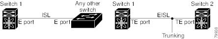
Trunking, also known as VSAN trunking, is a feature specific to switches in the Cisco MDS 9000 Family. Trunking enables interconnect ports to transmit and receive frames in more than one VSAN, over the same physical link, using enhanced ISL (EISL) frame format (see Figure 24-1).
Figure 24-1 Trunking
The trunking feature includes the following restrictions:
•
Trunking configurations are only applicable to E ports. If trunk mode is enabled in an E port and that port becomes operational as a trunking E port, it is referred to as a TE port.
•
•
Note
Trunking Configuration Guidelines
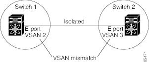
If you misconfigure VSAN configurations across E ports, you could face consequences such as merging the traffic in two VSANs (thus causing both VSANs to mismatch). The trunking protocol validates the VSAN interfaces at both ends of an ISL to avoid merging VSANs (see Figure 24-2).
Figure 24-2 VSAN Mismatch
In this example, the trunking protocol detects potential VSAN merging and isolates the ports involved.
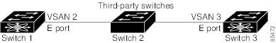
The trunking protocol cannot detect merging of VSANs when a third-party switch is placed in between two Cisco MDS 9000 Family switches (see Figure 24-3).
Figure 24-3 Third-Party Switch VSAN Mismatch
VSAN 2 and VSAN 3 are effectively merged with overlapping entries in the name server and the zone applications. The Cisco MDS 9000 Fabric Manager helps detect such topologies.
Trunking Protocol
The trunking protocol is important for E-port and TE-port operations. It supports the following:
•
•
•
By default, the trunking protocol is enabled. If the trunking protocol is disabled on a switch, no port on that switch can apply new trunk configurations. Existing trunk configurations are not affected—the TE port continues to function in trunk mode, but only supports traffic in VSANs that it negotiated with previously (when the trunking protocol was enabled). Also, other switches that are directly connected to this switch are similarly affected on the connected interfaces. In some cases, you may need to merge traffic from different port VSANs across a non-trunking ISL. If so, disable the trunking protocol.
Note
Tip
This section explains how to configure trunking and contains the following topics:
•
•
About Trunk Mode
By default, trunk mode is enabled in all Fibre Channel interfaces. However, trunk mode configuration takes effect only in E-port mode. You can configure trunk mode as on (enabled), off (disabled), or auto (automatic). The default trunk mode is on. The trunk mode configuration at the two ends of an ISL, between two switches, determine the trunking state of the link and the port modes at both ends (see Table 24-1).
Tip
Note
Configuring Trunk Mode
To configure trunk mode using Fabric Manager, follow these steps:
Step 1
Step 2
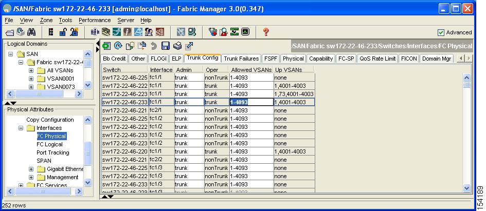
You see the information shown in Figure 24-4.
Figure 24-4 Trunking Configuration
Step 3
Step 4
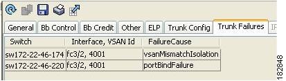
You see the reason listed in the FailureCause column (see Figure 24-5).
Figure 24-5 Trunk Failures Tab
Step 5
About Trunk-Allowed VSAN Lists
Each Fibre Channel interface has an associated trunk-allowed VSAN list. In TE-port mode, frames are transmitted and received in one or more VSANs specified in this list. By default, the VSAN range (1 through 4093) is included in the trunk-allowed list.
The common set of VSANs that are configured and active in the switch are included in the trunk-allowed VSAN list for an interface, and they are called allowed-active VSANs. The trunking protocol uses the list of allowed-active VSANs at the two ends of an ISL to determine the list of operational VSANs in which traffic is allowed.
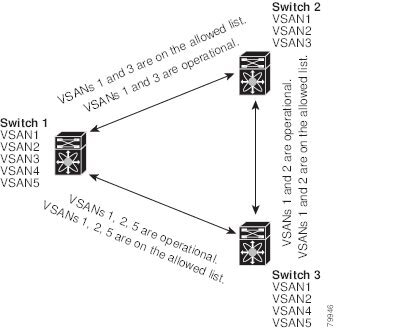
In Figure 24-6, switch 1 has VSANs 1 through 5, switch 2 has VSANs 1 through 3, and switch 3 has VSANs 1, 2, 4, and 5 with a default configuration of trunk-allowed VSANs. All VSANs configured in all three switches are allowed-active. However, only the common set of allowed-active VSANs at the ends of the ISL become operational as shown in Figure 24-6.
Figure 24-6 Default Allowed-Active VSAN Configuration
You can configure a select set of VSANs (from the allowed-active list) to control access to the VSANs specified in a trunking ISL.
Using Figure 24-6 as an example, you can configure the list of allowed VSANs on a per-interface basis (see Figure 24-7). For example, if VSANs 2 and 4 are removed from the allowed VSAN list of ISLs connecting to switch 1, the operational allowed list of VSANs for each ISL would be as follows:
•
•
•
Consequently, VSAN 2 can only be routed from switch 1 through switch 3 to switch 2.
Figure 24-7 Operational and Allowed VSAN Configuration
Configuring an Allowed-Active List of VSANs
To configure an allowed-active list of VSANs for an interface using Fabric Manager, follow these steps:
Step 1
You see the interface configuration in the Information pane.
Step 2
You see the current trunk configuration.
Step 3
Step 4
Default Settings
Table 24-2 lists the default settings for trunking parameters.
Table 24-2 Default Trunk Configuration Parameters
Switch port trunk mode
On.
Allowed VSAN list
1 to 4093 user-defined VSAN IDs.
Trunking protocol
Enabled.