Congestion Management

Low-latency queuing with strict priority queuing

Low-latency queuing with strict priority queuing is a QoS congestion management feature that

  • integrates strict priority queuing into the Class-Based Weighted Fair Queuing (CBWFQ) model

  • ensures delay-sensitive traffic is always dequeued ahead of other traffic classes, and

  • minimizes latency and jitter for critical applications such as voice and real-time video.

CBWFQ is a QoS scheduling model that assigns bandwidth to traffic classes based on configured weights and ensures each class receives its allocated portion of service during congestion.

Priority Queuing is a scheduling method that dequeues packets from the highest-priority queue before any other queue, allowing delay-sensitive traffic to pre-empt lower-priority classes; in strict priority mode, lower-priority queues may not be serviced if high-priority traffic is continuously present.

Table 1. Feature History Table

Feature Name

Release Information

Feature Description

Priority Propagation on Egress Queues

Release 26.3.1

Introduced in this release on: Fixed Systems (8700 [ASIC: K100])(select variants only*)

*This feature is supported on Cisco 8711-28H8F-M routers.

Priority Propagation on Egress Queues

Release 26.3.1

Introduced in this release on: Modular Systems (8800 [LC ASIC: K100])(select variants only*)

*This feature is supported on Cisco 88-LC1-16H16F-EM line cards.

Priority Propagation on Egress Queues

Release 26.1.1

Introduced in this release on: Centralized Systems (8400 [ASIC: K100])(select variants only*)

* This feature is now supported on Cisco 8404-SYS-D routers.

Priority Propagation on Egress Queues

Release 25.4.1

Introduced in this release on: Fixed Systems (8700 [ASIC: K100], 8010 [ASIC: A100]) (select variants only*)

*This feature is supported on:

  • 8711-48Z-M

  • 8011-32Y8L2H2FH

  • 8011-12G12X4Y-A/D

Priority Propagation on Egress Queues

Release 25.1.1

Introduced in this release on: Fixed Systems (8700 [ASIC: K100], 8010 [ASIC: A100])(select variants only*)

This feature is supported on:

  • 8712-MOD-M

  • 8011-4G24Y4H-I

Low Latency Queueing with Strict Priority Queueing

Release 26.3.1

Introduced in this release on: Fixed Systems (8700 [ASIC: K100])(select variants only*)

*This feature is supported on Cisco 8711-28H8F-M routers.

Low Latency Queueing with Strict Priority Queueing

Release 26.3.1

Introduced in this release on: Modular Systems (8800 [LC ASIC: K100])(select variants only*)

*This feature is supported on Cisco 88-LC1-16H16F-EM line cards.

Low Latency Queueing with Strict Priority Queueing

Release 25.4.1

Introduced in this release on: Fixed Systems (8700 [ASIC: K100], 8010 [ASIC: A100]) (select variants only*)

*This feature is supported on:

  • 8011-32Y8L2H2FH

  • 8011-12G12X4Y-A/D

Low Latency Queueing with Strict Priority Queueing

Release 25.1.1

Introduced in this release on: Fixed Systems (8010 [ASIC: A100])(select variants only*)

*This feature is supported on Cisco 8011-4G24Y4H-I routers.

Low Latency Queueing with Strict Priority Queueing

Release 24.4.1

Introduced in this release on: Fixed Systems (8700) (select variants only*)

This feature ensures that time-sensitive traffic receives dedicated priority, ensuring minimal latency and jitter while congestion for other types of traffic is managed fairly, guaranteeing high performance for critical applications and efficient overall traffic management.

*This functionality is now supported on Cisco 8712-MOD-M routers.

Priority Propagation on Egress Queues

Release 24.3.1

Introduced in this release on: Fixed Systems (8200 [ASIC: P100], 8700 [ASIC: P100])(select variants only*); Modular Systems (8800 [LC ASIC: P100])(select variants only*)

You can now ensure that high-priority traffic is consistently prioritized across multiple sub-interfaces on the same network port, enhancing the performance of critical applications.

This is achieved by enabling support for egress queuing policy maps that allow high-priority P1 traffic (on class TC7) to take precedence over non-P1 traffic across sub-interfaces. This feature ensures that critical traffic, such as voice or real-time video, is always given the highest priority, regardless of the sub-interface it is associated with, thereby maintaining optimal network performance and reducing latency for essential services.

*This feature is supported on:

  • 8212-48FH-M

  • 8711-32FH-M

  • 88-LC1-36EH

  • 88-LC1-12TH24FH-E

  • 88-LC1-52Y8H-EM

Low Latency Queueing with Strict Priority Queueing

Release 24.3.1

Introduced in this release on: Modular Systems (8800 [LC ASIC: P100]) (select variants only*), Fixed Systems (8200) (select variants only*), Fixed Systems (8700 (P100, K100)) (select variants only*)

This feature ensures that time-sensitive traffic receives dedicated priority, ensuring minimal latency and jitter while congestion for other types of traffic is managed fairly, guaranteeing high performance for critical applications and efficient overall traffic management.

*This feature is supported on:

  • 88-LC1-12TH24FH-E

  • 88-LC1-52Y8H-EM

  • 8212-48FH-M

  • 8711-32FH-M

Low Latency Queueing with Strict Priority Queueing

Release 24.2.11

Introduced in this release on: Modular Systems (8800 [LC ASIC: P100])(select variants only*)

With this feature, time-sensitive traffic receives dedicated priority, ensuring minimal latency and jitter while congestion for other types of traffic is managed fairly, guaranteeing high performance for critical applications and efficient overall traffic management.

You can also configure low latency queueing with strict priority queueing at the subinterface level, ensuring that the strict priority policy applies only to traffic on that specific subinterface, not the entire physical interface. This configuration is useful in scenarios where multiple services share the same physical link but have different QoS requirements.

*This feature is supported on 88-LC1-36EH.

Guidelines for configuring low-latency queuing with strict priority queuing

Priority and scheduling behavior

  • Only priority levels 1 to 7 are supported, where 1 is the highest and 7 is the lowest priority; the default CoSQ 0 has the lowest priority among all classes.

  • Egress policing is not supported, and in strict priority mode, heavy priority traffic can prevent lower-priority queues from being serviced.

  • The platform enforces a strict class hierarchy, where higher traffic classes take precedence over lower ones. This hierarchy can be redefined through an egress queuing policy map when configuring LLQ with strict priority.

  • When operating in strict-priority mode, egress scheduling follows the default class order TC7 >TC6 > TC5 > TC4 >TC3 > TC2 > TC1 > TC0, unless a queuing policy map overrides this behavior.

Shaping and rate control

  • You can configure shape average and queue-limit commands along with the priority command.

  • An optional shaper can be configured to cap the maximum traffic rate and prevent starvation of lower-priority traffic classes.

Interface-level configuration

LLQ with strict priority queuing can also be applied at the subinterface level, allowing strict priority behavior to affect only the specific subinterface rather than the entire physical interface.

Configure low-latency queuing with strict priority queuing

Before you begin

Ensure that you have an existing QoS class map that classifies the intended traffic.

Follow these steps to configure LLQ with strict priority on an egress interface.

Procedure


Step 1

Create or modify a policy-map that applies LLQ with strict priority.

This policy-map defines the class of traffic that receives strict priority handling.

Example:


            Router# configure
            Router(config)# policy-map test-priority-1
            Router(config-pmap)# class qos1
            Router(config-pmap-c)# priority level 7
            Router(config-pmap-c)# exit
            Router(config-pmap)# exit
          

The policy-map now includes a strict priority class with the specified priority level.

Step 2

(Optional) Shape the strict priority class to a specific bit rate.

Shaping prevents lower-priority queues from starving during high volumes of strict priority traffic.

Example:

Router(config-pmap-c)# shape average percent 40
          

Step 3

Apply the policy-map to the egress interface.

Attaching the policy-map makes strict priority queuing active for egress traffic on the specified interface.

Example:

Router(config)# interface HundredGigE 0/6/0/18
Router(config-if)# service-policy output test-priority-1
Router(config-if)# no shutdown
Router(config-if)# commit
          

The LLQ strict priority policy is now active on the selected output interface.

Step 4

Verify the strict priority behavior on the interface.

Confirm that the strict priority class (for example, HP7) is visible in the queue statistics.

Example:


            Router# show qos interface HundredGigE 0/6/0/18 output
            
            NOTE:- Configured values are displayed within parentheses
            Interface HundredGigE0/6/0/18 ifh 0x3000220  -- output policy
            NPU Id:                        3
            Total number of classes:       3
            Interface Bandwidth:           100000000 kbps
            VOQ Base:                      11176
            VOQ Stats Handle:              0x88550ea0
            Accounting Type:               Layer1 (Include Layer 1 encapsulation and above)
            ------------------------------------------------------------------------------
            Level1 Class (HP7)                       =   qos1
            Egressq Queue ID                         =   11177 (HP7 queue)
            TailDrop Threshold                       =   125304832 bytes / 10 ms (default)
            WRED not configured for this class
            
            Level1 Class (HP6)                       =   qos-2
            Egressq Queue ID                         =   11178 (HP6 queue)
            TailDrop Threshold                       =   125304832 bytes / 10 ms (default)
            WRED not configured for this class
            
            Level1 Class (class-default)
            Egressq Queue ID                         =   11176 (Default LP queue)
            Queue Max. BW.                           =   101803495 kbps (default)
            Queue Min. BW.                           =   0 kbps (default)
            Inverse Weight / Weight                  =   1 (BWR not configured)
            TailDrop Threshold                       =   1253376 bytes / 10 ms (default)
            WRED not configured for this class
          

The interface shows the strict priority class and confirms that LLQ with strict priority is functioning as expected.


Bandwidth remaining percent for class-based queuing

Bandwidth remaining percent for class-based queuing is an egress congestion-management feature that

  • uses the bandwidth remaining percent percentage command to configure percentage-based sharing of available remaining bandwidth for a traffic class,

  • lets you express class-based queue bandwidth shares with values from 1 to 100 instead of ratio values, and

  • supports egress class-based queuing on supported main interfaces and subinterfaces for Layer 2 and Layer 3 use cases.

Use bandwidth remaining percent when you want the configured QoS policy to reflect how service classes, customer classes, AI workload traffic classes, or data center front-end traffic classes share available remaining egress bandwidth during congestion.

Bandwidth remaining percent does not guarantee bandwidth. It distributes available remaining bandwidth among eligible queues after priority traffic and explicit bandwidth reservations are serviced.

Before Cisco IOS XR Release 26.3.1 , supported Cisco 8000 Series routers used bandwidth remaining ratio for remaining-bandwidth allocation. With bandwidth remaining percent, you can configure percentage values directly and avoid translating service intent into ratio values.

The following table provides release information for bandwidth remaining percent.

Table 2. Feature History Table

Feature Name

Release Information

Feature Description

Bandwidth remaining percent for class-based queuing

Release 26.3.1

Introduced in this release on:

Fixed Systems (8200 [ASIC: P100], 8700 [ASIC: P100, K100], 8010 [ASIC: A100]); Centralized Systems (8400 [ASIC: K100]); Modular Systems (8800 [LC ASIC: P100, K100])

You can configure percentage-based sharing of remaining egress bandwidth among class-based queues on supported main interfaces and subinterfaces. This helps service provider and data center operators express bandwidth-sharing policies for customer services, AI workloads, and application traffic more intuitively without calculating scheduler ratios.

Bandwidth remaining percent and bandwidth remaining ratio both define how eligible class-based queues share available remaining egress bandwidth. Choose one method in a policy map.

Table 3. Bandwidth remaining percent and bandwidth remaining ratio

Bandwidth Remaining Percent

Bandwidth Remaining Ratio

Uses percentage values, such as bandwidth remaining percent 10 , to express the remaining-bandwidth share for a class.

Uses ratio values to express the relative remaining-bandwidth share for a class.

Helps align class-based queue bandwidth shares with service or workload intent that is already defined in percentages.

Helps define relative class weights when the policy design uses ratio-based scheduling values.

Is mutually exclusive with bandwidth remaining ratio in the same policy map.

Is mutually exclusive with bandwidth remaining percent in the same policy map.

The following table summarizes how bandwidth remaining percent relates to shaping and policing.

Table 4. Bandwidth remaining percent, shaping, and policing

Bandwidth Remaining Percent

Traffic Shaping

Traffic Policing

Shares available remaining egress bandwidth among eligible queues during congestion.

Controls the egress transmission rate by scheduling packets to a configured rate.

Enforces an ingress or egress traffic contract by transmitting, marking, or dropping traffic.

Uses bandwidth remaining percent percentage .

Uses commands such as shape average .

Uses commands such as police rate .

In show qos interface output, the configured percentage appears in parentheses in the Inverse Weight / Weight field.

Class-based remaining-bandwidth allocation

An operator wants to share available remaining egress bandwidth across service classes on a supported Cisco 8000 Series router. The policy assigns 10 percent shares to several traffic classes, a 5 percent share to another traffic class, and a priority level to latency-sensitive traffic.

During congestion, the bandwidth remaining percent classes share available remaining egress bandwidth according to the configured percentage values. The priority class uses priority queuing behavior, and the configured percentage values appear in the show qos interface output for the bandwidth remaining percent classes.

What bandwidth remaining percent is not

Bandwidth remaining percent is not to be confused with traffic shaping. It does not configure a fixed output rate for a class. Use shaping when you need to cap or smooth egress traffic to a configured rate.

Bandwidth remaining percent is not to be confused with traffic policing. It does not enforce a token-bucket traffic contract or define conform, exceed, or violate actions. Use policing when you need to enforce traffic rates by transmitting, marking, or dropping traffic.

Bandwidth remaining percent is also not a bandwidth guarantee or a tuning interface for the internal inverse-weight conversion. Configure the percentage value that matches the intended remaining-bandwidth sharing policy and use verification output to confirm the programmed value.

Benefits of bandwidth remaining percent for class-based queuing

Use this reference to identify the benefits, supported scope, and verification behavior for bandwidth remaining percent on supported Cisco 8000 Series routers.

Bandwidth remaining percent provides these benefits:

  • Percentage-based policy expression: You can configure remaining-bandwidth sharing with percentage values instead of calculating scheduler ratios.

  • Clearer service intent: QoS policies clarify how customer services, service classes, and application traffic share available remaining egress bandwidth during congestion.

  • Operational readability: Percentage values in policy maps are easier to review, communicate, and audit than ratio-only scheduling values.

  • AI and data center traffic planning: You can express bandwidth-sharing policies for competing non-priority flows, such as inference, storage, telemetry, checkpointing, and data center front-end traffic.

  • Main-interface and subinterface coverage: You can use bandwidth remaining percent on supported main interfaces and subinterfaces for Layer 2 and Layer 3 use cases.

  • Verification clarity: The show qos interface output displays the configured percentage in parentheses in the Inverse Weight / Weight field.

The following table lists the supported scope and behavior for bandwidth remaining percent.

Verification commands for bandwidth remaining percent

The following table shows what to verify in the command output for bandwidth remaining percent.

Table 5. Verification commands and output cues

Command

What the Output Shows

What to Check

show policy-map type qos interface interface output pmap-name policy-map-name

Classification statistics, transmitted traffic, dropped traffic, and queueing statistics for each class.

Check the queue ID and tail-drop counters for each class that is part of the egress queuing policy.

show qos interface interface output

Programmed queue details, including queue type and the Inverse Weight / Weight field.

Check that configured bandwidth remaining percent values appear in parentheses in the Inverse Weight / Weight field.

show policy-map pmap-name policy-map-name detail

The policy-map definition, class maps, bandwidth remaining percent values, and priority configuration.

Confirm that the configured policy contains the expected classes, bandwidth remaining percent values, and any priority class.

The following table shows the visible variations from the sample show qos interface output.

Table 6. Output variations for bandwidth remaining percent

Policy Configuration

Queue Type in Output

Inverse Weight / Weight Output

User Interpretation

bandwidth remaining percent 10

LP queue

5 / (10%)

The class is configured for a 10 percent share of available remaining egress bandwidth.

bandwidth remaining percent 5

LP queue

9 / (5%)

The class is configured for a 5 percent share of available remaining egress bandwidth.

priority level 1

HP1 queue

Not displayed for bandwidth remaining percent

The class uses priority queuing behavior and is not a bandwidth remaining percent class.

class-default without bandwidth remaining percent

Default LP queue

1 / (BWR not configured)

The default class does not have bandwidth remaining percent configured in the sample policy.

Guidelines for bandwidth remaining percent for class-based queuing

Use bandwidth remaining percent for bandwidth-sharing policies

Use bandwidth remaining percent when you want to express how eligible class-based queues share available remaining egress bandwidth during congestion.

  • Choose this option when service intent is easier to describe as percentage-based sharing than as scheduler ratios.

  • Apply it for competing non-priority flows, such as customer services, application traffic, inference, storage, telemetry, checkpointing, and data center front-end traffic.

This guideline applies to egress class-based queuing policies on supported main interfaces and subinterfaces for Layer 2 and Layer 3 use cases.

Percentage values make the policy intent easier to review, communicate, and audit than ratio-only scheduling values.

Bandwidth remaining percent does not guarantee bandwidth. The scheduler distributes available remaining bandwidth among eligible queues after priority traffic and explicit bandwidth reservations are serviced.

If you require a fixed maximum egress rate, configure shaping separately. For traffic-contract enforcement, use policing. For strict latency, use priority queuing.

Choose one remaining-bandwidth method per policy map

Configure either bandwidth remaining percent or bandwidth remaining ratio in a policy map.

  • Use bandwidth remaining percent when the policy design uses percentage-based sharing.

  • Use bandwidth remaining ratio when the policy design uses ratio-based scheduling weights.

This guideline applies within a single policy map.

In two-level queuing, the parent policy performs only traffic shaping. Bandwidth remaining ratio and bandwidth remaining percent apply to the child policy that performs class-based scheduling.

Mixing remaining-bandwidth ratio and percent across parent and child policies is not a valid use case.

Remove one remaining-bandwidth method from the policy map, and keep only the method that matches the policy design.

Configure supported values and interface scope

Configure bandwidth remaining percent percentage with a value from 1 to 100 on supported egress class-based queuing policies.

  • Ensure that the sum of all bandwidth remaining percent values configured across classes in the same policy map does not exceed 100 percent.

  • Apply the policy in the output direction.

  • Use the feature on supported main interfaces and subinterfaces for Layer 2 and Layer 3 scenarios.

  • For subinterface bandwidth distribution, configure bandwidth remaining percent in the parent policy map.

This guideline applies to supported A100, K100, and P100-based Cisco 8000 Series routers.

Staying within the supported value range, direction, and interface scope keeps the policy aligned with the documented feature behavior.

For unsupported interfaces, directions, or platforms, use an existing supported QoS mechanism for the policy goal.

Use shaping only for maximum-rate behavior

Add shaping only when the policy design requires peak information rate (PIR) or maximum-rate behavior.

  • Use bandwidth remaining percent for percentage-based sharing of available remaining egress bandwidth.

  • Use shape average when a class or parent policy must cap egress traffic to a configured rate.

  • Use shaping separately when the policy design requires peak information rate (PIR) or maximum-rate behavior.

This guideline applies when determining whether the bandwidth remaining percent configuration example or deployment policy also needs a shaper.

The bandwidth remaining percent example in this content does not include shape average , and shaping is not always required for this feature. This feature adds percentage-based remaining-bandwidth sharing; it does not add committed information rate (CIR) configuration with the bandwidth command.

Keeping remaining-bandwidth sharing and maximum-rate behavior separate helps users understand whether the policy is sharing remaining bandwidth, capping traffic, or doing both.

If the deployment requires a PIR or maximum-rate behavior, add the appropriate shaping configuration and verify it separately from the bandwidth remaining percent values.

Do not modify parent-class bandwidth remaining percent in place on subinterfaces

You cannot modify the parent-class bandwidth remaining percent value in place when it is configured for a subinterface.

This guideline applies to parent-level bandwidth remaining percent configuration specific to subinterface scheduling.

In-place modification is not supported for this subinterface parent-class configuration.

If you try to modify the value in place, the router displays this error: !!% Unsupported class-action: In Place modification of parent BRR not supported for sub-interfaces: InPlace Modify Error:

To change the value, detach the service policy, update the configuration, and then reapply the service policy.

Configure bandwidth remaining percent for class-based queuing

Use this task to configure percentage-based sharing of available remaining egress bandwidth among class-based queues.

  • Use percentage values when the policy intent is easier to express as service, customer, application, or AI workload bandwidth-sharing percentages than as scheduler ratios.

  • The configured percentage is a share of available remaining bandwidth during congestion. It is not a fixed bandwidth guarantee.

This example matches traffic by traffic-class values and and configures bandwidth remaining percent values to egress queues: 10 percent to traffic classes 1 through 5, 5 percent to class 6, and priority queuing to class 7.

The example does not include shape average . Add shaping only when the policy design requires peak information rate (PIR) or maximum-rate behavior.

Replace the class names, policy-map name, interface, traffic classes, and percentage values with values for your network.

Before you begin

  • Verify that your router supports bandwidth remaining percent on egress class-based queuing policies.

  • Identify the traffic classes that must share available remaining egress bandwidth.

  • Determine the percentage value for each class. The valid range is 1 to 100, and the sum of all bandwidth remaining percent values for classes in the same policy map must not exceed 100 percent.

  • Do not configure bandwidth remaining ratio and bandwidth remaining percent in the same policy map.

  • Identify the interface or subinterface where you want to attach the egress policy.

Follow these steps to configure bandwidth remaining percent for class-based queuing.

Procedure


Step 1

Enter global configuration mode.

Example:

Router#configure 

Step 2

Create class maps to identify the traffic classes that require bandwidth remaining percent or priority queuing.

Example:

Router(config)#class-map match-any classmap_1_1_1_0 
Router(config-cmap)#match traffic-class 1 
Router(config-cmap)#exit 
Router(config)#class-map match-any classmap_1_2_1_0 
Router(config-cmap)#match traffic-class 2 
Router(config-cmap)#exit 
Router(config)#class-map match-any classmap_1_3_1_0 
Router(config-cmap)#match traffic-class 3 
Router(config-cmap)#exit 
Router(config)#class-map match-any classmap_1_4_1_0 
Router(config-cmap)#match traffic-class 4 
Router(config-cmap)#exit 
Router(config)#class-map match-any classmap_1_5_1_0 
Router(config-cmap)#match traffic-class 5 
Router(config-cmap)#exit 
Router(config)#class-map match-any classmap_1_6_1_0 
Router(config-cmap)#match traffic-class 6 
Router(config-cmap)#exit 
Router(config)#class-map match-any classmap_1_7_1_0 
Router(config-cmap)#match traffic-class 7 
Router(config-cmap)#exit 

This example uses traffic-class values as the match criteria. Use the match criteria that apply to your QoS design.

The class maps identify the traffic that the egress policy uses for bandwidth-sharing and priority treatment.

Step 3

Create a policy map and configure bandwidth remaining percent values for the required traffic classes.

Example:

Router(config)#policy-map policymap_1_1_0 
Router(config-pmap)#class classmap_1_1_1_0 
Router(config-pmap-c)#bandwidth remaining percent 10 
Router(config-pmap-c)#exit 
Router(config-pmap)#class classmap_1_2_1_0 
Router(config-pmap-c)#bandwidth remaining percent 10 
Router(config-pmap-c)#exit 
Router(config-pmap)#class classmap_1_3_1_0 
Router(config-pmap-c)#bandwidth remaining percent 10 
Router(config-pmap-c)#exit 
Router(config-pmap)#class classmap_1_4_1_0 
Router(config-pmap-c)#bandwidth remaining percent 10 
Router(config-pmap-c)#exit 
Router(config-pmap)#class classmap_1_5_1_0 
Router(config-pmap-c)#bandwidth remaining percent 10 
Router(config-pmap-c)#exit 
Router(config-pmap)#class classmap_1_6_1_0 
Router(config-pmap-c)#bandwidth remaining percent 5 
Router(config-pmap-c)#exit 
Router(config-pmap)#class classmap_1_7_1_0 
Router(config-pmap-c)#priority level 1 
Router(config-pmap-c)#exit 
Router(config-pmap)#class class-default 
Router(config-pmap-c)#exit 
Router(config-pmap)#end-policy-map 

Classes configured with bandwidth remaining percent share available remaining egress bandwidth after priority traffic and explicit bandwidth reservations are serviced. The class configured with priority level 1 uses priority queuing behavior and is not a bandwidth remaining percent class.

The policy map defines percentage-based remaining-bandwidth shares for the eligible traffic classes.

Step 4

Apply the policy map to the interface in the egress direction.

Example:

Router(config)#interface HundredGigE0/0/0/4/0 
Router(config-if)#service-policy output policymap_1_1_0 

The output direction is the egress direction. Apply the policy to the supported interface or subinterface where you want the scheduler to share available remaining bandwidth by percentage.

Step 5

Commit the configuration.

Example:

Router(config-if)#commit 
Router(config-if)#end 

The router attaches the egress QoS policy to the interface.

Step 6

Verify traffic and queueing statistics for the egress policy.

Example:

Router#show policy-map type qos interface HundredGigE0/0/0/4/0 output pmap-name policymap_1_1_0 

HundredGigE0/0/0/4/0 output: policymap_1_1_0

Class classmap_1_1_1_0
  Classification statistics          (packets/bytes)     (rate - kbps)
    Matched             :          1845070012/674656525964         17297419
    Transmitted         :          1501200962/548657330452         14067302
    Total Dropped       :           343869050/125999195512          3230117
  Queueing statistics
    Queue ID                             : 929
    Taildropped(packets/bytes)           : 343869050/125999195512

Class classmap_1_6_1_0
  Classification statistics          (packets/bytes)     (rate - kbps)
    Matched             :          1845071526/674681793280         17299080
    Transmitted         :           834389984/304799226144          7814944
    Total Dropped       :          1010681542/369882567136          9484136
  Queueing statistics
    Queue ID                             : 934
    Taildropped(packets/bytes)           : 1010681542/369882567136

Class classmap_1_7_1_0
  Classification statistics          (packets/bytes)     (rate - kbps)
    Matched             :          1845071797/674708349485         17300036
    Transmitted         :          1845071797/674708349485         17300036
    Total Dropped       :                   0/0                    0
  Queueing statistics
    Queue ID                             : 935
    Taildropped(packets/bytes)           : 0/0

Class class-default
  Classification statistics          (packets/bytes)     (rate - kbps)
    Matched             :                   0/0                    0
    Transmitted         :                   0/0                    0
    Total Dropped       :                   0/0                    0

The output excerpt shows active classes, queue IDs, transmitted traffic, and tail-drop counters. Use these counters to confirm that the egress policy is active during congestion.

The statistics confirm that the configured classes are participating in egress queuing, which is where the bandwidth remaining percent policy applies.

Step 7

Verify the programmed queue behavior and configured percentages.

Example:

Router#show qos interface HundredGigE0/0/0/4/0 output 
NOTE:- Configured values are displayed within parentheses
Interface HundredGigE0/0/0/4/0 ifh 0x78000408  -- output policy
NPU Id:                        0
Total number of classes:       8
Interface Bandwidth:           100000000 kbps
Policy Name:                   policymap_1_1_0
VOQ Base:                      928
Accounting Type:               Layer1 (Include Layer 1 encapsulation and above)
VOQ Mode:                      8
Shared Counter Mode:           1
------------------------------------------------------------------------------
Level1 Class                             =   classmap_1_1_1_0
Egressq Queue ID                         =   929 (LP queue)
Queue Max. BW.                           =   no max (default)
Inverse Weight / Weight                  =   5 / (10%)
TailDrop Threshold                       =   608256 bytes / 5 ms (default)
WRED not configured for this class

Level1 Class                             =   classmap_1_2_1_0
Egressq Queue ID                         =   930 (LP queue)
Queue Max. BW.                           =   no max (default)
Inverse Weight / Weight                  =   5 / (10%)
TailDrop Threshold                       =   608256 bytes / 5 ms (default)
WRED not configured for this class

Level1 Class                             =   classmap_1_3_1_0
Egressq Queue ID                         =   931 (LP queue)
Queue Max. BW.                           =   no max (default)
Inverse Weight / Weight                  =   5 / (10%)
TailDrop Threshold                       =   608256 bytes / 5 ms (default)
WRED not configured for this class

Level1 Class                             =   classmap_1_4_1_0
Egressq Queue ID                         =   932 (LP queue)
Queue Max. BW.                           =   no max (default)
Inverse Weight / Weight                  =   5 / (10%)
TailDrop Threshold                       =   608256 bytes / 5 ms (default)
WRED not configured for this class

Level1 Class                             =   classmap_1_5_1_0
Egressq Queue ID                         =   933 (LP queue)
Queue Max. BW.                           =   no max (default)
Inverse Weight / Weight                  =   5 / (10%)
TailDrop Threshold                       =   608256 bytes / 5 ms (default)
WRED not configured for this class

Level1 Class                             =   classmap_1_6_1_0
Egressq Queue ID                         =   934 (LP queue)
Queue Max. BW.                           =   no max (default)
Inverse Weight / Weight                  =   9 / (5%)
TailDrop Threshold                       =   608256 bytes / 5 ms (default)
WRED not configured for this class

Level1 Class (HP1)                       =   classmap_1_7_1_0
Egressq Queue ID                         =   935 (HP1 queue)
Queue Max. BW.                           =   no max (default)
TailDrop Threshold                       =   59996160 bytes / 5 ms (default)
WRED not configured for this class

Level1 Class                             =   class-default
Egressq Queue ID                         =   928 (Default LP queue)
Queue Max. BW.                           =   no max (default)
Inverse Weight / Weight                  =   1 / (BWR not configured)
TailDrop Threshold                       =   608256 bytes / 5 ms (default)
WRED not configured for this class

Check the percentage in parentheses in the Inverse Weight / Weight field. The classes configured with bandwidth remaining percent 10 display 5 / (10%) . The class configured with bandwidth remaining percent 5 displays 9 / (5%) .

The priority class appears as an HP1 queue instead of a bandwidth remaining percent queue. The class-default class displays BWR not configured because this example does not configure bandwidth remaining percent under class-default .

The output confirms that the scheduler programmed the configured bandwidth remaining percent values for the eligible queues and preserved priority behavior for the priority class.

Step 8

Verify the configured policy definition.

Example:

Router#show policy-map pmap-name policymap_1_1_0 detail 
class-map match-any classmap_1_1_1_0
 match traffic-class 1
 end-class-map
!
class-map match-any classmap_1_2_1_0
 match traffic-class 2
 end-class-map
!
class-map match-any classmap_1_3_1_0
 match traffic-class 3
 end-class-map
!
class-map match-any classmap_1_4_1_0
 match traffic-class 4
 end-class-map
!
class-map match-any classmap_1_5_1_0
 match traffic-class 5
 end-class-map
!
class-map match-any classmap_1_6_1_0
 match traffic-class 6
 end-class-map
!
class-map match-any classmap_1_7_1_0
 match traffic-class 7
 end-class-map
!
policy-map policymap_1_1_0
 class classmap_1_1_1_0
  bandwidth remaining percent 10
 !
 class classmap_1_2_1_0
  bandwidth remaining percent 10
 !
 class classmap_1_3_1_0
  bandwidth remaining percent 10
 !
 class classmap_1_4_1_0
  bandwidth remaining percent 10
 !
 class classmap_1_5_1_0
  bandwidth remaining percent 10
 !
 class classmap_1_6_1_0
  bandwidth remaining percent 5
 !
 class classmap_1_7_1_0
  priority level 1
 !
 class class-default
 !
 end-policy-map
!

The policy definition confirms that the configured bandwidth remaining percent values and priority level 1 setting match the policy that is attached to the interface.


The interface has an egress class-based queuing policy that shares available remaining bandwidth among eligible queues by percentage. During congestion, the configured bandwidth remaining percent values make the service-class intent easier to verify without calculating bandwidth remaining ratios.

What to do next

After you deploy the policy, monitor the queue statistics for the configured traffic classes and adjust the percentage values if the bandwidth-sharing policy changes.

  • Use show qos interface to confirm that the configured percentages remain visible in the Inverse Weight / Weight field.

  • If you need to cap traffic to a maximum egress rate, configure shaping separately and verify the shaping behavior separately.

Traffic shaping

Traffic shaping is a QoS congestion management feature that

  • regulates the flow of outbound traffic to match the speed or bandwidth profile of the downstream interface

  • buffers excess packets during congestion instead of dropping them, and

  • ensures traffic conforms to contracted or expected rate profiles to prevent bottlenecks in topologies with data-rate mismatches.

Key functions of traffic shaping

  • Buffering: is a key function of traffic shaping in which excess packets are temporarily stored instead of being dropped, allowing the system to release them later at a controlled rate when bandwidth becomes available.

  • Rate profiling: is a traffic-control concept that defines the maximum transmission rate a flow must conform to so that it matches the expected bandwidth or contract of the downstream interface.

Guidelines for configuring traffic shaping

Supported traffic direction

Only egress traffic shaping is supported.

Class and policy requirements

  • You must configure all eight qos-group classes—including class-default—in the egress QoS policy.

  • You can configure the shape average command together with the priority command when shaping traffic.

  • We recommended that you configure all eight traffic-class classes—including class-default—in the egress policies.

  • Only a limited set of traffic-class class combinations is supported.

Traffic-type considerations

Egress interfaces that carry both unicast and multicast traffic may handle traffic classes inconsistently when shaping is enabled. Therefore, configure shaping primarily on ports that carry only unicast traffic.

Configure traffic shaping

This procedure applies only to configuring traffic shaping on main interfaces.

Before you begin

Ensure that you have an existing QoS class map for the traffic class you intend to shape.

Follow these steps to configure traffic shaping on a main interface.

Procedure


Step 1

Create or modify a policy-map to configure traffic shaping for a specific class.

This policy-map defines the shaping rate applied to the outbound traffic class.

Example:

Router# configure
Router(config)# policy-map egress_policy1
Router(config-pmap)# class c5
Router(config-pmap-c)# shape average percent 40
Router(config-pmap-c)# exit
Router(config-pmap)# exit
          

The policy-map now includes a shaping configuration for the selected traffic class.

Step 2

Attach the shaping policy-map to the egress interface.

Applying the service policy activates traffic shaping for outbound traffic on that interface.

Example:

Router(config)# interface HundredGigE 0/1/0/0
Router(config-if)# service-policy output egress_policy1
Router(config-if)# commit
          

The traffic shaping configuration is now active on the selected output interface.

Running Configuration

policy-map egress_policy1
 class c5
  shape average percent 40
 !
 class class-default
 !
 end-policy-map
!

interface HundredGigE0/6/0/18
 service-policy input 100g-s1-1
 service-policy output egress_policy1
!

Step 3

Verify the shaping configuration on the interface.

Check that the class displays the expected shaping rate and queue behavior.

Example:

Router# show qos interface HundredGigE 0/6/0/18 output
            
 NOTE:- Configured values are displayed within parentheses
Interface HundredGigE0/6/0/18 ifh 0x3000220  -- output policy
NPU Id:                        3
Total number of classes:       2
Interface Bandwidth:           100000000 kbps
VOQ Base:                      11176
VOQ Stats Handle:              0x88550ea0
Accounting Type:               Layer1 (Include Layer 1 encapsulation and above)
------------------------------------------------------------------------------
Level1 Class                             =   c5
Egressq Queue ID                         =   11177 (LP queue)
Queue Max. BW.                           =   40329846 kbps (40 %)
Queue Min. BW.                           =   0 kbps (default)
Inverse Weight / Weight                  =   1 (BWR not configured)
Guaranteed service rate                  =   40000000 kbps
TailDrop Threshold                       =   50069504 bytes / 10 ms (default)
WRED not configured for this class

Level1 Class                             =   class-default
Egressq Queue ID                         =   11176 (Default LP queue)
Queue Max. BW.                           =   101803495 kbps (default)
Queue Min. BW.                           =   0 kbps (default)
Inverse Weight / Weight                  =   1 (BWR not configured)
Guaranteed service rate                  =   50000000 kbps
TailDrop Threshold                       =   62652416 bytes / 10 ms (default)
WRED not configured for this class
          

The interface output shows that shaping is applied with the configured rate and class behavior.


Egress class-level traffic shaping on subinterfaces

Egress class-level traffic shaping on subinterfaces is a QoS traffic shaping feature that

  • provides class-level rate limiters or shaping on each traffic class in an egress subinterface queuing policy map

  • provides granular control of outbound traffic on individual classes, and

  • enables efficient bandwidth allocation when multiple services share the same physical link or LAG.

Table 7. Feature History Table

Feature Name

Release Information

Feature Description

Egress class-level traffic shaping for subinterfaces

Release 26.3.1

Introduced in this release on: Fixed Systems (8700 [ASIC: K100])(select variants only*)

*This feature is supported on Cisco 8711-28H8F-M routers.

Egress class-level traffic shaping for subinterfaces

Release 26.3.1

Introduced in this release on: Modular Systems (8800 [LC ASIC: K100])(select variants only*)

*This feature is supported on Cisco 88-LC1-16H16F-EM line cards.

Egress class-level traffic shaping for subinterfaces

Release 26.1.1

Introduced in this release on: Centralized Systems (8400 [ASIC: K100])(select variants only*)

* This feature is now supported on Cisco 8404-SYS-D routers.

Egress class-level traffic shaping for subinterfaces

Release 25.4.1

Introduced in this release on: Fixed Systems (8010 [ASIC: A100], 8700 [ASIC: K100])

*This feature is supported on:

  • 8011-32Y8L2H2FH

  • 8011-12G12X4Y-A/D

  • 8711-48Z-M

Egress class-level traffic shaping for subinterfaces

Release 25.1.1

Introduced in this release on: Fixed Systems (8700 [ASIC: K100], 8010 [ASIC: A100])(select variants only*)

Egress class-level traffic shaping for subinterfaces is now supported on the fixed systems using K100 and A100 Silicon One ASICs.

This feature is supported on:

  • 8712-MOD-M

  • 8011-4G24Y4H-I

Egress class-level traffic shaping for subinterfaces

Release 24.3.1

Introduced in this release on: Fixed Systems (8200 [ASIC: P100], 8700 [ASIC: P100])(select variants only*); Modular Systems (8800 [LC ASIC: P100])(select variants only*)

You can now granularly control the traffic flow on each class in the egress queuing policy map ensuring optimal bandwidth allocation and improved network performance.

This is achieved by introducing support for enabling class-level rate limiting traffic shapers for each class in the egress subinterface-level (main and LAG) queuing policy maps.

*This feature is enabled by default and supported on:

  • 8212-48FH-M

  • 8711-32FH-M

  • 88-LC1-36EH

  • 88-LC1-12TH24FH-E

  • 88-LC1-52Y8H-EM

Guidelines for configuring egress class-level traffic shaping on subinterfaces

Traffic-type considerations

Shaping of multicast traffic is not supported on egress subinterfaces configured in the non-ETM mode.

Traffic policing

Traffic policing is a QoS congestion management feature that

  • limits the maximum rate of traffic entering or leaving an interface by enforcing compliance with a configured bandwidth profile

  • uses a token bucket algorithm to determine whether each packet conforms to or exceeds a configured rate profile and applies the corresponding transmit or drop action, and

  • applies immediate actions—such as transmitting, marking, or dropping packets—without buffering excess traffic.

Key concepts of traffic policing

  • Token bucket: is a rate-control mechanism that accumulates tokens at a configured rate and uses them to determine whether packets conform to or exceed a traffic policer’s allowed bandwidth profile.

  • Conform, exceed, and violate actions: are policing outcomes that classify each packet based on whether it fits within the allowed rate: conforming packets are transmitted, exceeding packets may be marked or dropped, and violating packets are typically dropped according to the configured policing mode.

  • Committed Information Rate (CIR): is the sustained bandwidth level that a policer guarantees for a traffic flow, defining the average rate at which tokens are added to the token bucket.

  • Peak Information Rate (PIR): is the upper bandwidth limit configured for two-rate policers, defining the maximum rate at which traffic is allowed to be sent when both the committed and peak token buckets contain sufficient tokens.

  • Committed Burst (Bc): or Committed Burst Size (CBS) is the maximum amount of data that can be sent at once while still conforming to the CIR, representing the number of bytes or time interval that the committed token bucket can hold at full capacity.

    This value represents the capacity of the primary token bucket. The larger the value, the more tolerant the policer is of momentary traffic bursts above the average rate.

  • Excess Burst (Be): or Excess Burst Size (EBS) is the additional amount of data that may be permitted beyond the committed burst when excess tokens are available, allowing short-term transmission above the CIR before packets are treated as exceeding or violating the rate.

    Excess Burst (Be) is an optional parameter used in traffic policing, specifically within a two-bucket, three-color policing mode, to allow for a secondary, higher level of burst tolerance beyond the Committed Burst (Bc)

Types of traffic policing modes

This section outlines the traffic-policing modes supported on your router.

  • Single-Rate policer

    • Single-rate two-color (1R2C) policer: is a rate-control mode that uses a single token bucket and classifies each packet as either conform or exceed based on the CIR, applying corresponding actions such as transmit or drop.

  • Two-rate policer

    • Two-rate three-color (2R3C) policer: is a metering mode that uses two token buckets—one for the CIR and one for the peak information rate (PIR)—to classify packets into conform, exceed, or violate actions, enforcing both a sustained rate limit and a peak rate limit.

Single-rate two-color policers

The single-rate two-color (1R2C) policer is a traffic-policing feature that

  • uses a single token bucket to meter packets against a configured committed information rate (CIR)

  • classifies each packet as either conforming or exceeding the allowed rate based solely on the available committed burst tokens, and

  • applies fixed policing actions—transmit for conforming packets and drop for exceeding packets—without buffering excess traffic.

Guidelines for configuring single-rate two-color policers

Default policer actions

  • The policer always transmits packets that conform to the CIR.

  • The policer always drops packets that exceed the CIR.

  • The default actions cannot be modified, regardless of class configuration or policy-map settings.

How the single-rate two-color policer works

Summary

The key components involved in the single-rate two-color policer are:

  • Traffic policer: A metering function on the interface that evaluates each packet against a configured committed information rate (CIR) and burst parameters, then applies a conform or exceed action based on that evaluation.

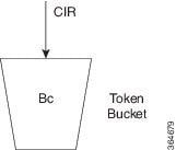
  • Token bucket (Tc): A logical bucket that accumulates tokens at the CIR up to a configured committed burst value (Bc). The number of tokens represents how much traffic can be sent at any given moment.

  • Committed information rate (CIR): The configured average rate (in bits per second) at which the policer replenishes tokens and against which packet sizes are evaluated.

The single-rate two-color policer meters traffic by updating a single token bucket at the committed information rate and comparing the size of each packet against the available tokens. Based on this comparison, the policer classifies each packet as conforming or exceeding the CIR and applies the corresponding default action. This process limits the maximum traffic rate on the interface without buffering excess packets.

Workflow

Figure 1. Workflow for single-rate two-color policers

These stages describe how the single-rate two-color policer works.

  1. The router receives packets on an interface with a single-rate two-color policer configured. The traffic policer on the interface inspects each incoming packet and prepares to meter it against the configured committed information rate (CIR) and burst parameters.
  2. The policer updates the token bucket based on the committed information rate. At every refresh interval, the policer adds tokens to the token bucket (Tc) at a rate equal to the CIR, up to the committed burst value (Bc). Tokens represent the amount of traffic that can be sent at the committed rate.
  3. The policer compares the packet size to the available tokens. For each packet of size B, the policer checks whether the current token count in the bucket is sufficient to accommodate the packet. If the bucket holds enough tokens, the packet can conform to the CIR; otherwise, the packet exceeds the CIR.
  4. The policer classifies conforming packets and applies the conform action. If the packet size B is less than or equal to the number of tokens in the bucket, the packet conforms. The policer decrements the token bucket by B and applies the conform action, which transmits the packet.
  5. The policer classifies exceeding packets and applies the exceed action. If the packet size B is greater than the number of available tokens in the bucket, the packet exceeds the CIR. The policer applies the exceed action, which drops the packet for the single-rate two-color policer. Excess packets are not buffered for later transmission.
  6. The policer continues metering traffic to enforce the configured rate.

Result

As traffic continues to arrive, the policer repeats the cycle of replenishing tokens, classifying packets as conform or exceed, and applying the corresponding actions. This ongoing process enforces the configured committed information rate on the interface without buffering excess packets.

Configure single-rate two-color policers

Before you begin

Prepare or identify a class map that matches the traffic you want to police.

Follow these steps to configure traffic policing (1R2C) on an ingress interface.

Procedure

Step 1

Create or modify a policy-map to apply the single-rate two-color policer to a traffic class.

This step creates a policy-map that applies a 1R2C policer to a class of traffic. The policer limits the rate for that class on the ingress interface.
Example:
Router# configure
Router(config)# policy-map test-police-1R2C
Router(config-pmap)# class dscp1
Router(config-pmap-c)# police rate 10 gbps
Router(config-pmap-c-police)# exit
Router(config-pmap-c)# exit
Router(config-pmap)# exit
          

The policy-map now includes a single-rate two-color policer that enforces a 10-Gbps committed rate for the dscp1 class.

Step 2

Attach the policing policy-map to the ingress interface.

Attaching the policy-map enables traffic policing on the selected interface in the ingress direction.
Example:
Router(config)# interface HundredGigE 0/0/0/18
Router(config-if)# service-policy input test-police-1R2C
Router(config-if)# commit
          

The single-rate two-color policer is now active on the specified input interface.

Running Configuration:

class-map match-any dscp1
 match dscp ipv4 1
 end-class-map
!
!
policy-map test-police-1R2C
 class dscp1
  police rate 10 gbps
  !
 !
 class class-default
  !
 !
 end-policy-map
!
!
interface HundredGigE0/0/0/8
service-policy input test-police-1R2C
!

Step 3

Verify the traffic policing configuration and policer statistics.

Example:
Router# show qos interface HundredGigE 0/0/0/8 input
NOTE:- Configured values are displayed within parentheses
Interface HundredGigE0/0/0/8 ifh 0xf0001e8  -- input policy
NPU Id:                        0
Total number of classes:       2
Interface Bandwidth:           100000000 kbps
Policy Name:                   test-police-1R2C
Accounting Type:               Layer1 (Include Layer 1 encapsulation and above)
------------------------------------------------------------------------------
Level1 Class                             =   dscp1
Policer committed rate                   =   10000000 kbps (10 gbits/sec)
Policer conform burst                    =   1024000 bytes (default)
Policer conform action                   =   Just TX
Policer exceed action                    =   DROP PKT

Level1 Class                             =   class-default
Policer not configured for this class
          

The output confirms that the input interface is using the test-police-1R2C policy and that the dscp1 class is policed at the configured rate with the expected conform and exceed actions.


Two-rate three-color policers

The two-rate three-color (2R3C) policer is a traffic-policing feature that

  • uses two token buckets, a committed bucket and a peak bucket, to meter traffic at both the committed information rate (CIR) and the peak information rate (PIR)

  • classifies each packet into one of three conformance levels—conform, exceed, or violate—based on the configured rates and burst parameters, and

  • applies predefined per-color actions in which conform and exceed traffic are transmitted and violate traffic is dropped.

Guidelines for configuring two-rate three-color policers

Default policer actions

  • The policer always transmits packets that conform to the committed or peak information rates.

  • The policer always drops packets that violate the configured rate thresholds.

  • You cannot modify these default actions, regardless of class configuration or policy-map settings.

How the two-rate three-color policer works

Summary

The key components involved in two-rate three-color policing are:

  • Committed information rate (CIR): The configured average rate (in bits per second) at which the policer replenishes tokens and against which packet sizes are evaluated.

  • Peak information rate (PIR): The higher metering rate that allows short-term bursts above the CIR, up to a configured peak limit.

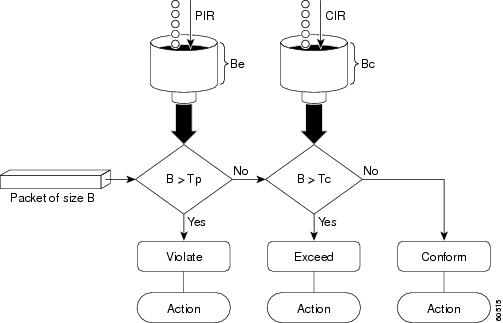
  • Committed token bucket (Tc): A token bucket associated with the CIR that determines whether packets conform to the committed rate.

  • Peak token bucket (Tp): A token bucket associated with the PIR that determines whether packets exceed the committed rate but still remain within the peak rate.

The two-rate three-color policer uses the committed and peak token buckets together to meter packets against CIR and PIR and to assign a color-based action that enforces the configured traffic policy at the ingress interface.

Workflow

Figure 2. Workflow for two-rate three-color policers

These stages describe how the two-rate three-color policer works.

  1. The policer initializes the committed and peak token buckets. The committed bucket is sized by the committed burst (Bc), and the peak bucket is sized by the peak burst (Be). Both buckets start accumulating tokens as soon as the policer is active. Based on the configured committed information rate (CIR), peak information rate (PIR), and burst parameters, the router initializes the committed and peak token buckets used to meter incoming traffic.
  2. The policer refreshes tokens based on the CIR and PIR. When a packet arrives at the interface, then
    • the committed bucket is refilled at the CIR rate, up to Bc, and
    • the peak bucket is refilled at the PIR rate, up to Be.
    This dual-rate update occurs each time traffic arrives, ensuring both long-term and peak-rate metering.
  3. The policer evaluates the packet size against both token buckets. The policer compares the packet’s size (B) with the committed and then the peak bucket.
    Table 8. Packet evaluation against token buckets
    When… Then…
    the packet size B is less than or equal to the committed token bucket (Tc) the policer determines that the committed bucket has enough tokens and classifies the packet as conform.
    the packet size B is greater than Tc but less than or equal to the peak token bucket (Tp) the policer determines that the committed bucket overflows, but the peak bucket can accommodate the packet, and classifies it as exceed.
    the packet size B is greater than Tp the policer determines that neither bucket has enough tokens and classifies the packet as violate.
  4. The policer assigns a color to the packet based on CIR and PIR.
    Table 9. Packet color assignment
    When… Then…
    the packet size B is less than or equal to the committed token bucket (Tc) the policer assigns the packet the conform (green) color.
    the packet size B is greater than Tc but less than or equal to the peak token bucket (Tp) the policer assigns the packet the exceed (yellow) color because it does not fit in the committed bucket but still fits within the peak bucket.
    the packet size B is greater than Tp the policer assigns the packet the violate (red) color because it does not fit in either token bucket and exceeds the PIR.
  5. The policer applies the default transmit or drop actions for each color.
    Table 10. Color-based policer actions
    When… Then…
    a packet is classified as conform (green) the packet is transmitted, and the policer decrements both the committed and peak token buckets by the packet size B.
    a packet is classified as exceed (yellow) the packet is transmitted, the committed bucket is decremented by B, and the peak bucket is decremented by the overflow amount.
    a packet is classified as violate (red) the packet is dropped, and the peak token bucket is not decremented.

Result

As traffic continues to arrive, the policer repeatedly refreshes tokens in both the committed and peak buckets, evaluates packet sizes against the available tokens, assigns each packet a conform, exceed, or violate color, and applies the corresponding predefined actions. This continuous metering process enforces both the committed and peak information rates on the interface and ensures that exceeding and violating traffic is handled according to the policer’s color-based rules.

Configure two-rate three-color policers

Before you begin

Prepare or identify a class map that matches the traffic you want to police.

Follow these steps to configure two-rate three-color traffic policing (2R3C) on an ingress interface.

Procedure

Step 1

Create or modify a policy-map to apply the two-rate three-color policer to a traffic class.

This step creates a policy-map that applies a 2R3C policer to a class of traffic. The policer meters traffic using a committed information rate (CIR) and a peak information rate (PIR).
Example:
Router# configure
Router(config)# policy-map test-police-2R3C
Router(config-pmap)# class dscp1
Router(config-pmap-c)# police rate 10 gbps peak-rate 20 gbps
Router(config-pmap-c-police)# exit
Router(config-pmap-c)# exit
Router(config-pmap)# exit

The policy-map now includes a two-rate three-color policer with a 10 Gbps committed rate and a 20 Gbps peak rate for the dscp1 class.

Step 2

Attach the policing policy-map to the ingress interface.

Attaching the policy-map enables two-rate three-color traffic policing on the selected interface in the ingress direction.
Example:
Router(config)# interface HundredGigE 0/0/0/8
Router(config-if)# service-policy input test-police-2R3C
Router(config-if)# commit

The two-rate three-color policer is now active on the specified input interface.

Running Configuration:

class-map match-any dscp1
match dscp ipv4 1
end-class-map
!
!
policy-map test-police-2R3C
class dscp1
police rate 10 gbps peak-rate 20 gbps
!
!
class class-default
!
!
end-policy-map
!
!
interface HundredGigE0/0/0/8
service-policy input test-police-2R3C
!

Step 3

Verify the two-rate three-color traffic policing configuration and policer statistics.

  1. Verify the policer configuration applied on the ingress interface.

    Example:
    Router# show qos interface HundredGigE 0/0/0/8 input
    NOTE:- Configured values are displayed within parentheses
    |Interface HundredGigE0/0/0/8 ifh 0xf0001e8  -- input policy
    |NPU Id:||0
    |Total number of classes:       2
    |Interface Bandwidth:           100000000 kbps
    |Policy Name:|       test-police-2R3C
    |Accounting Type:|   Layer1 (Include Layer 1 encapsulation and above)
    |------------------------------------------------------------------------------
    |Level1 Class||     =   dscp1
    |Policer committed rate|       =   10000000 kbps (10 gbits/sec)
    |Policer peak rate||=   20000000 kbps (20 gbits/sec)
    |Policer conform burst|        =   1024000 bytes (default)
    |Policer exceed burst|         =   2048000 bytes (default)
    |Policer conform action|       =   Just TX
    |Policer exceed action|        =   DROP PKT
    |Policer violate action|       =   DROP PKT
    |
    |Level1 Class||     =   class-default
    |Policer not configured for this class
  2. Review detailed policer statistics on the ingress interface.

    Example:
    Router# policy-map interface HundredGigE 0/0/0/8 input
    |HundredGigE0/0/0/8 input: test-police-2R3C
    |
    |Class dscp1
    |Classification statistics          (packets/bytes)     (rate - kbps)
    |Matched| :           289228439/289228439000         27734775
    |Transmitted         :|56422213/56422213000          5410359
    |Total Dropped       :           232806226/232806226000         22324416
    |Policing statistics|    (packets/bytes)     (rate - kbps)
    |Policed(conform)    :|56422213/56422213000          5410359
    |Policed(exceed)     :|56422215/56422215000          5410358
    |Policed(violate)    :           176384011/176384011000         16914058
    |Policed and dropped :           232806226/232806226000
    |Class class-default
    |Classification statistics          (packets/bytes)     (rate - kbps)
    |Matched| :|61136620/61136620000          0
    |Transmitted         :|61136620/61136620000          0
    |Total Dropped       :|       0/0|        0
    |Policy Bag Stats time: 1570155764000  [Local Time: 10/04/19 02:22:44.000]

The output confirms that the input interface is using the test-police-2R3C policy and that the dscp1 class is metered at the configured committed and peak rates with the expected conform, exceed, and violate actions.


Two-level hierarchical ingress policing

Two-level hierarchical ingress policing is an ingress QoS traffic-policing feature that

  • uses a parent policer to enforce an aggregate ingress rate for a customer, service, or traffic aggregate,

  • preserves child policers for per-class or per-application committed and peak rate treatment, and

  • prioritizes traffic that child policers classify as conforming over child exceed or violate traffic when the policy is designed for child-conform-aware behavior.

From Cisco IOS XR Release 26.3.1 , you can configure the parent policer under the parent class-default class. The parent policy contains only the default parent class, and the child policy is attached under that class.

Use this model when you need both aggregate ingress enforcement and child class-level policing in the same policy hierarchy. For example, a service provider can enforce a contracted customer aggregate while individual application classes keep their own policers.

Table 11. Feature History Table

Feature Name

Release Information

Feature Description

Two-level hierarchical ingress policing

Release 26.3.1

Introduced in this release on: Fixed Systems (8200 [ASIC: P100], 8700 [ASIC: P100, K100], 8010 [ASIC: A100]); Centralized Systems (8400 [ASIC: K100]); Modular Systems (8800 [LC ASIC: P100, K100]).

You can enforce an aggregate bandwidth limit for a customer, service, or traffic aggregate while preserving per-class traffic policies. This helps keep aggregate ingress traffic within contracted bandwidth limits while maintaining application-level and class-level traffic handling.

The parent policer and child policers provide different levels of control in the same ingress policy hierarchy.

Table 12. Parent and child policer roles

Aspect

Parent Policer

Child Policers

Policy level

Configured under parent class-default in the parent policy map.

Configured under classes in the child policy map that is attached to the parent class.

Primary role

Enforces the aggregate ingress rate for the policy hierarchy.

Enforce class-level or application-level committed and peak rates.

Traffic treatment

Evaluates traffic after child policing and determines the final aggregate policing behavior.

Classify packets as conform, exceed, or violate before parent policing.

Verification output

Appears as Level1 Class = class-default in show qos interface interface input output.

Appear as Level2 Class entries in show qos interface interface input output.

Two-level hierarchical ingress policing uses the same policer concepts as the existing single-rate, two-rate, and configurable-burst policer content. The difference is the hierarchy: the parent policer controls the aggregate ingress rate, and the child policers control the traffic classes under that aggregate.

Applications under a customer aggregate

A service provider applies an ingress policy to keep a customer aggregate within its contracted bandwidth. Under that aggregate, child policers continue to enforce class-level treatment for application traffic, such as voice, business-critical data, storage, telemetry, checkpointing, or AI inference traffic.

When the parent CIR is greater than or equal to the sum of the child CIRs and the parent actions support the intended excess-traffic handling, the parent policer can prioritize child-conforming traffic over child-exceed or child-violate traffic. This design helps keep traffic within the aggregate ingress contract without flattening all application classes into one policer.

What two-level hierarchical ingress policing is not

Two-level hierarchical ingress policing is not automatically child-conform-aware for every parent and child policer configuration. A parent committed information rate (CIR) lower than the sum of child CIRs, or a parent action configuration that drops traffic the design expects to transmit, does not provide the intended child-conform-aware behavior.

Household budget analogy

Think of hierarchical policing as managing a household budget. You can set spending controls for individual categories, such as groceries, travel, and entertainment, while also enforcing an overall monthly spending limit. Similarly, child policers control individual traffic classes, while the parent policer controls their aggregate traffic rate.

Benefits and scope of two-level hierarchical ingress policing

Use this reference to identify the benefits and supported scope for two-level hierarchical ingress policing.

Two-level hierarchical ingress policing provides these benefits:

  • Aggregate ingress enforcement: You can enforce an aggregate ingress rate for a customer, service, or traffic aggregate.

  • Class-level traffic control: You can preserve child policers for individual traffic classes or applications under the aggregate policer.

  • Child-conform-aware design: You can design policies so that the parent policer gives preference to traffic that child policers classify as conforming over child exceed or violate traffic.

  • Existing MQC workflow: You use the existing policy-map , service-policy , and police rate command model.

  • Flexible hierarchical policy design: You can combine aggregate ingress rate enforcement with class-specific traffic controls in a single hierarchical policy structure.

    This capability can be useful in service provider and data center networks that carry multiple application or workload traffic classes under a common aggregate bandwidth limit.

The following table lists key reference details for two-level hierarchical ingress policing.

Table 13. Reference details for two-level hierarchical ingress policing

Reference Item

Supported Value or Behavior

Applies To

Notes

Direction

Ingress (input)

Ingress QoS policy maps

The feature enforces traffic contracts at ingress by using parent and child policers.

Parent policy scope

Parent class-default

Parent policy map

The parent policy contains only the default parent class. Attach the child policy under this class and configure the parent policer under the same class.

Child policy scope

Child classes with 1R2C or 2R3C policers

Child policy map

Child policers continue to classify traffic as conform, exceed, or violate before parent policing.

Interface scope

Physical main interfaces and subinterfaces, bundle main interfaces and subinterfaces

Layer 2 and Layer 3 interface scenarios

This scope reflects the supported interface coverage for Cisco IOS XR Release 26.3.1.

Parent policer variants

1R3C parent, 2R3C parent, and 1R2C parent with user-configured burst

Parent policer under parent class-default

A single-rate parent policer is 1R3C by default. You can configure a 1R2C parent policer by using police rate with a user-defined burst value. You can configure a 2R3C parent policer by using police rate with the peak-rate keyword to specify the peak information rate (PIR).

Parent policer processing

Parent policing occurs after child policing

Packets not dropped by child policers

The child policer result is available to the parent policer when the parent policer evaluates the aggregate traffic.

Guidelines and restrictions for two-level hierarchical ingress policing

Configure the parent policer under parent class-default

Configure the parent policer under the parent class-default class.

  • Use only the parent class-default class in the parent policy map.

  • Attach the child policy map under the parent class-default class by using service-policy .

  • Configure the parent policer under the same parent class-default class.

This guideline applies to two-level hierarchical ingress policing.

For two-level hierarchical ingress policing, parent policer support is delivered for the default parent class.

The parent policer appears as Level1 Class = class-default in show qos interface interface input output.

Apply the parent policy in the input direction

Apply the parent policy map to the interface in the input direction.

This guideline applies when you attach a parent policy map that contains a parent policer and a child service policy to a supported interface.

Two-level hierarchical ingress policing is an ingress QoS feature.

The parent and child policers are programmed for the input policy on the interface.

Attach the parent policy by using service-policy input parent-policy-name .

Use supported platforms and interfaces

Configure two-level hierarchical ingress policing only on supported Cisco 8000 Series routers and supported interface types.

  • Use this feature on A100, K100, and P100- based Cisco 8000 Series routers.

  • Use this feature on supported physical main interfaces and subinterfaces, and on supported bundle main interfaces and bundle subinterfaces.

This guideline applies when you attach a parent policy map with a parent policer to an interface.

If you apply a policy with a parent policer to an unsupported fixed system or line card, the commit fails and the router displays this error in show configuration failed output: !!% 'DPA_QOSEA' detected the 'warning' condition 'Hierarchical policers are not supported.'

Use a supported Cisco 8000 Series router and supported interface type, or remove the parent policer from the policy.

Configure child-conform-aware policies deliberately

Configure the parent committed information rate (CIR) greater than or equal to the sum of the child CIRs when you want child-conform-aware behavior.

  • Configure child policers for the child classes that must participate in child-conform-aware behavior.

  • Configure exceed-action transmit on the parent policer when the design requires the parent policer to transmit child exceed traffic.

This guideline applies to policies designed to prioritize child-conforming traffic over child exceed or violate traffic.

A child-conform-aware parent policer honors the child policer classification when deciding whether to admit traffic.

If the parent CIR is lower than the sum of the child CIRs, the configuration is allowed, but the parent policer does not provide child-conform-aware behavior. Parent policing behavior is also not child-conform-aware if exceed-action transmit is not configured on the parent policer. Child-conform-aware behavior is not possible when one or more child classes are unpoliced.

Adjust the parent CIR, child CIRs, child policer coverage, or parent policer actions so that the configured policy matches the intended child-conform-aware behavior.

Align child transmit actions with parent transmit actions

Do not configure a child policer exceed-action transmit action when the parent policer has the corresponding drop action.

This guideline applies when a child policer is configured to transmit exceed traffic under a parent policer.

A parent drop action overrides the corresponding child transmit action.

When the child policer action has no effect because the parent policer overwrites it, the router displays a system message such as: %QOS-DPA_QOSEA-5-CHILD_POLICER_ACTION_HAS_NO_EFFECT : In policy-map parent, the class-default child class policer's configured exceed action has no effect, the action is unconditionally overwritten by the parent policer drop action

If the design requires child exceed traffic to be transmitted, configure the corresponding parent policer action to transmit. Otherwise, remove the child transmit action if you do not want to configure an action that the parent policer overrides.

If the child policer is configured with exceed-action transmit and the parent policer is configured with exceed-action drop, child transmit and drop stats may be inaccurate. The child policer counts the exceeding packets as transmitted, even though those packets are later dropped by the parent policer.

Plan discard-class marking at the parent policer

Do not rely on child policer set discard-class marking when a parent policer is configured.

This guideline applies when a child policer action sets discard-class in a two-level hierarchical ingress policing policy.

The parent policer sets the final discard-class value and unconditionally overwrites the child policer discard-class marking.

When the child policer discard-class action has no effect because the parent policer overwrites it, the router displays a system message such as: %QOS-DPA_QOSEA-5-CHILD_POLICER_ACTION_HAS_NO_EFFECT : In policy-map parent, the class-default child class policer's 'set discard-class' exceed action has no effect, the action is unconditionally overwritten by the parent policer

Replace the child set discard-class action with the transmit action to avoid the QOS-DPA_QOSEA-5-CHILD_POLICER_ACTION_HAS_NO_EFFECT system message.

Interpret child policer statistics carefully

Interpret child policer statistics carefully because parent policing can affect child policer counters in a two-level hierarchical ingress policing policy.

The configured policer actions and final traffic throughput are as expected. However, child policer counters can be inaccurate in these scenarios:

  • A child policer is configured with exceed-action transmit, and the parent policer is configured with exceed-action drop. In this scenario, the child policer transmit and drop counters may be inaccurate. The child policer counts the exceeding packets as transmitted, even though the parent policer later drops those packets.

  • The parent policer is congested, and one of these rate conditions is true: the parent committed information rate (CIR) is lower than the sum of the child policer CIRs, or the parent peak information rate (PIR) is lower than the sum of the child policer PIRs. In this scenario, the child policer conform, exceed, and transmit counters may be inaccurate.

    Parent policer congestion occurs when the sum of the child conforming traffic rates is greater than the configured parent CIR, or when the sum of the child exceeding traffic rates is greater than the configured parent PIR.

In the parent policer congestion scenario, child policer conform, exceed, and transmit counters may be higher than expected for the child policer configuration. These counters may be close to the child matched counters, depending on traffic patterns. The child matched counters remain accurate.

Use show policy-map interface <interface><input> to review parent policer statistics and child policer statistics together when you verify policy behavior.

Configure two-level hierarchical ingress policing

Use this task to configure a two-level hierarchical ingress policing policy for a customer, service, or traffic aggregate.

  • The parent policer enforces the aggregate ingress rate.

  • The child policers enforce per-class committed and peak rates under the parent policer.

This example configures four child classes under a parent policer. The child committed information rates (CIRs) are 1 Gbps, 2 Gbps, 6 Gbps, and 7 Gbps. The parent CIR is 16 Gbps, which equals the sum of the child CIRs.

The complete configuration in this task uses a two-rate, three-color (2R3C) parent policer with a 16 Gbps committed information rate (CIR) and a 20 Gbps peak information rate (PIR). For a one-rate, three-color (1R3C) parent policer, retain the same child CIRs and configure the parent with a 16 Gbps CIR without a peak rate. The two variants therefore use the same child policing rates but apply different rate models at the parent level.

Replace the class names, policy-map names, interface, match criteria, and policer rates with values for your network.

Before you begin

  • Verify that your Cisco 8000 Series router supports two-level hierarchical ingress policing.

  • Identify the interface where you want to apply the parent policy map in the input direction.

  • Identify the child traffic classes and the committed or peak rates that each class requires.

  • Use only the parent class-default class in the parent policy map.

  • Configure the parent CIR greater than or equal to the sum of the child CIRs when you want child-conform-aware behavior.

Follow these steps to configure two-level hierarchical ingress policing.

Procedure

Step 1

Enter global configuration mode.

Example:
Router# configure

Step 2

Create class maps to identify the child traffic classes.

Example:
Router(config)# class-map match-all IN_CMAP_DSCP_56
Router(config-cmap)# match dscp 56
Router(config-cmap)# exit
Router(config)# class-map match-all IN_CMAP_DSCP_48
Router(config-cmap)# match dscp 48
Router(config-cmap)# exit
Router(config)# class-map match-any IN_CMAP_DSCP_40
Router(config-cmap)# match dscp 40
Router(config-cmap)# exit

This example uses DSCP values as the match criteria. Use the match criteria that apply to your QoS design.

The class maps identify the child traffic classes that the child policy map polices.

Step 3

Create the child policy map and configure child policers.

Example:
Router(config)# policy-map IN_4_CHILD_TEST
Router(config-pmap)# class IN_CMAP_DSCP_56
Router(config-pmap-c)# set traffic-class 7
Router(config-pmap-c)# police rate 1 gbps
Router(config-pmap-c)# exit
Router(config-pmap)# class IN_CMAP_DSCP_48
Router(config-pmap-c)# set traffic-class 6
Router(config-pmap-c)# police rate 2 gbps
Router(config-pmap-c)# exit
Router(config-pmap)# class IN_CMAP_DSCP_40
Router(config-pmap-c)# set traffic-class 5
Router(config-pmap-c)# police rate 6 gbps peak-rate 20 gbps
Router(config-pmap-c-police)# exceed-action transmit
Router(config-pmap-c-police)# exit
Router(config-pmap-c)# exit
Router(config-pmap)# class class-default
Router(config-pmap-c)# police rate 7 gbps peak-rate 20 gbps
Router(config-pmap-c-police)# exceed-action transmit
Router(config-pmap-c-police)# exit
Router(config-pmap-c)# exit
Router(config-pmap)# end-policy-map

This child policy map uses the 2R3C parent policer example. For the 1R3C parent policer variant, use peak-rate 16 gbps for the two-rate child policers in classes IN_CMAP_DSCP_40 and class-default .

The child policy map defines per-class policers and marks traffic classes before parent policing.

Step 4

Create the parent policy map, attach the child policy, and configure the parent policer.

Example:
Router(config)# policy-map IN_PARENT_4_CHILD_TEST
Router(config-pmap)# class class-default
Router(config-pmap-c)# service-policy IN_4_CHILD_TEST
Router(config-pmap-c)# police rate 16 gbps peak-rate 20 gbps
Router(config-pmap-c-police)# exceed-action transmit
Router(config-pmap-c-police)# exit
Router(config-pmap-c)# exit
Router(config-pmap)# end-policy-map

This example configures a 2R3C parent policer. To configure the 1R3C parent policer variant, use police rate 16 gbps with exceed-action transmit under the parent class-default class.

The parent policy map contains the child policy and the parent policer under parent class-default .

Step 5

Apply the parent policy map to the interface in the input direction.

Example:
Router(config)# interface HundredGigE0/0/0/3
Router(config-if)# service-policy input IN_PARENT_4_CHILD_TEST

The input direction is the ingress direction.

The router applies the parent ingress QoS policy to the interface.

Step 6

Commit the configuration.

Example:
Router(config-if)# commit
Router(config-if)# end

Step 7

Verify the configured parent and child policy hierarchy.

Example:
Router# show policy-map pmap-name IN_PARENT_4_CHILD_TEST detail
class-map match-any class-default
 end-class-map
!
class-map match-all IN_CMAP_DSCP_56
 match dscp 56
 end-class-map
!
class-map match-all IN_CMAP_DSCP_48
 match dscp 48
 end-class-map
!
class-map match-any IN_CMAP_DSCP_40
 match dscp 40
 end-class-map
!
policy-map IN_4_CHILD_TEST
 class IN_CMAP_DSCP_56
  set traffic-class 7
  police rate 1 gbps
  !
 !
 class IN_CMAP_DSCP_48
  set traffic-class 6
  police rate 2 gbps
  !
 !
 class IN_CMAP_DSCP_40
  set traffic-class 5
  police rate 6 gbps peak-rate 20 gbps
   exceed-action transmit
  !
 !
 class class-default
  police rate 7 gbps peak-rate 20 gbps
   exceed-action transmit
  !
 !
 end-policy-map
!
policy-map IN_PARENT_4_CHILD_TEST
 class class-default
  service-policy IN_4_CHILD_TEST
  police rate 16 gbps peak-rate 20 gbps
   exceed-action transmit
  !
 !
 end-policy-map
!

The output confirms that the child policy map is attached under parent class-default and that the parent policer is configured under the same class.

Step 8

Verify that the parent and child policers are programmed on the interface.

Example:
Router# show qos interface HundredGigE0/0/0/3 input
NOTE:- Configured values are displayed within parentheses
Interface HundredGigE0/0/0/3 ifh 0x780001b0  -- input policy
NPU Id:                        0
Total number of classes:       5
Interface Bandwidth:           100000000 kbps
Policy Name:                   IN_PARENT_4_CHILD_TEST
Accounting Type:               Layer1 (Include Layer 1 encapsulation and above)
------------------------------------------------------------------------------
Level1 Class                             =   class-default
Policer committed rate                   =   16000000 kbps (16 gbits/sec)
Policer peak rate                        =   20000000 kbps (20 gbits/sec)
Policer conform burst                    =   4096000 bytes (default)
Policer exceed burst                     =   4096000 bytes (default)
Policer conform action                   =   Just TX
Policer exceed action                    =   Just TX
Policer violate action                   =   DROP PKT

   Level2 Class                             =   IN_CMAP_DSCP_56
   New traffic class                        =   7
   Policer committed rate                   =   1000000 kbps (1 gbits/sec)
   Policer conform burst                    =   1024000 bytes (default)
   Policer conform action                   =   Just TX
   Policer exceed action                    =   DROP PKT

   Level2 Class                             =   IN_CMAP_DSCP_48
   New traffic class                        =   6
   Policer committed rate                   =   2000000 kbps (2 gbits/sec)
   Policer conform burst                    =   1024000 bytes (default)
   Policer conform action                   =   Just TX
   Policer exceed action                    =   DROP PKT

   Level2 Class                             =   IN_CMAP_DSCP_40
   New traffic class                        =   5
   Policer committed rate                   =   6000000 kbps (6 gbits/sec)
   Policer peak rate                        =   20000000 kbps (20 gbits/sec)
   Policer conform action                   =   Just TX
   Policer exceed action                    =   Just TX
   Policer violate action                   =   DROP PKT

   Level2 Class                             =   class-default
   Policer committed rate                   =   7000000 kbps (7 gbits/sec)
   Policer peak rate                        =   20000000 kbps (20 gbits/sec)
   Policer conform action                   =   Just TX
   Policer exceed action                    =   Just TX
   Policer violate action                   =   DROP PKT

The parent policer appears as Level1 Class = class-default . The child policers appear as Level2 Class entries.

For the 1R3C parent policer variant, the parent Level1 Class = class-default output displays the 16 Gbps committed rate and does not display a parent peak rate. The two-rate child classes display 16 Gbps as their peak rate.

The output confirms that the parent and child policers are programmed on the input policy.

Step 9

Verify parent and child policer statistics.

Example:
Router#<userinput>show policy-map interface HundredGigE0/0/0/3 input</userinput>

HundredGigE0/0/0/3 input: IN_PARENT_4_CHILD_TEST

Class class-default
  Classification statistics          (packets/bytes)     (rate - kbps)
    Matched             :          6036378230/6036378230000        98038979
    Transmitted         :          1218109401/1218109401000        19768818
    Total Dropped       :          4818268829/4818268829000        78270161
  Policing statistics                (packets/bytes)     (rate - kbps)
    Policed(conform)    :           973485880/973485880000         15798604
    Policed(exceed)     :           244623521/244623521000         3970214
    Policed(violate)    :          4818268829/4818268829000        78270161
    Policed and dropped :          4818268829/4818268829000

  Policy IN_4_CHILD_TEST Class IN_CMAP_DSCP_56
    Classification statistics          (packets/bytes)     (rate - kbps)
      Matched             :          1509094690/1509094690000        24509737
      Transmitted         :            60817814/60817814000          987093
      Total Dropped       :          1448276876/1448276876000        23522644
    Policing statistics                (packets/bytes)     (rate - kbps)
      Policed(conform)    :            60817814/60817814000          987093
      Policed(exceed)     :          1448276876/1448276876000        23522644
      Policed(violate)    :                   0/0                    0
      Policed and dropped :          1448276876/1448276876000
      Policed and dropped(parent policer)  : 0/0

  Policy IN_4_CHILD_TEST Class IN_CMAP_DSCP_48
    Classification statistics          (packets/bytes)     (rate - kbps)
      Matched             :          1509094800/1509094800000        24509747
      Transmitted         :           121696005/121696005000         1975211
      Total Dropped       :          1387398795/1387398795000        22534536
    Policing statistics                (packets/bytes)     (rate - kbps)
      Policed(conform)    :           121696005/121696005000         1975211
      Policed(exceed)     :          1387398795/1387398795000        22534536
      Policed(violate)    :                   0/0                    0
      Policed and dropped :          1387398795/1387398795000
      Policed and dropped(parent policer)  : 0/0

  Policy IN_4_CHILD_TEST Class IN_CMAP_DSCP_40
    Classification statistics          (packets/bytes)     (rate - kbps)
      Matched             :          1509094905/1509094905000        24509746
      Transmitted         :          1509094905/1509094905000        24509746
      Total Dropped       :                   0/0                    0
    Policing statistics                (packets/bytes)     (rate - kbps)
      Policed(conform)    :           365170865/365170865000         5926650
      Policed(exceed)     :          1143924040/1143924040000        18583096
      Policed(violate)    :                   0/0                    0
      Policed and dropped :                   0/0
      Policed and dropped(parent policer)  : 0/0

  Policy IN_4_CHILD_TEST Class class-default
    Classification statistics          (packets/bytes)     (rate - kbps)
      Matched             :          1509095016/1509095016000        24509742
      Transmitted         :          1509095016/1509095016000        24509742
      Total Dropped       :                   0/0                    0
    Policing statistics                (packets/bytes)     (rate - kbps)
      Policed(conform)    :           425801627/425801627000         6909638
      Policed(exceed)     :          1083293389/1083293389000        17600104
      Policed(violate)    :                   0/0                    0
      Policed and dropped :                   0/0
      Policed and dropped(parent policer)  : 0/0

The parent class statistics show the aggregate parent policer behavior. The child policy statistics show all four child classes: IN_CMAP_DSCP_56 , IN_CMAP_DSCP_48 , IN_CMAP_DSCP_40 , and class-default . On Cisco 8000 Series routers, the Policed and dropped (parent policer) field is not supported and always displays 0/0 .

Child policer statistics can be inaccurate in specific scenarios because of parent policing behavior. The configured policer behavior and throughput are as expected, but review parent policer statistics and child policer statistics together when you verify policy behavior. For details, see Guidelines and restrictions for two-level hierarchical ingress policing.


The interface has an ingress QoS policy that enforces an aggregate parent policer rate while preserving per-class child policer behavior.

Use these traffic-rate outcomes to interpret the verified policy behavior.

Table 14. Verified behavior for parent policer variants

Parent Policer Variant

Traffic Condition

Observed Behavior

Statistics Note

1R3C parent policer

25 Gbps ingress rate for all four child classes.

All four child classes transmit at their CIRs: 1 Gbps, 2 Gbps, 6 Gbps, and 7 Gbps. The parent policer transmits at its 16 Gbps CIR.

Transmitted-rate statistics for child classes IN_CMAP_DSCP_40 and class-default , which use exceed-action transmit , can be inaccurate.

1R3C parent policer

The ingress rate is reduced to 1 Gbps for classes IN_CMAP_DSCP_48 and IN_CMAP_DSCP_40 .

Class IN_CMAP_DSCP_56 still transmits at its 1 Gbps CIR. Classes IN_CMAP_DSCP_48 and IN_CMAP_DSCP_40 transmit at their 1 Gbps ingress rate. Class class-default uses 6 Gbps of excess bandwidth and transmits at 13 Gbps. The parent policer transmits at its 16 Gbps CIR.

Transmitted-rate statistics for child class class-default can be inaccurate. Transmitted-rate statistics for child class IN_CMAP_DSCP_40 are accurate in this case because all packets are conforming.

2R3C parent policer

25 Gbps ingress rate for all four child classes.

Classes IN_CMAP_DSCP_56 and IN_CMAP_DSCP_48 transmit at their 1 Gbps and 2 Gbps CIRs. Classes IN_CMAP_DSCP_40 and class-default share 4 Gbps of excess bandwidth and each transmits about 2 Gbps above its CIR. The parent policer transmits at its 20 Gbps PIR.

Transmitted-rate statistics for child classes IN_CMAP_DSCP_40 and class-default , which use exceed-action transmit , can be inaccurate.

2R3C parent policer

The ingress rate is reduced to 1 Gbps for class IN_CMAP_DSCP_48 and to 3 Gbps for class class-default .

Class IN_CMAP_DSCP_56 still transmits at its 1 Gbps CIR. Classes IN_CMAP_DSCP_48 and class-default transmit at their 1 Gbps and 3 Gbps ingress rates. Class IN_CMAP_DSCP_40 uses all 9 Gbps of excess bandwidth and transmits at 15 Gbps. The parent policer transmits at its 20 Gbps PIR.

Transmitted-rate statistics for child class IN_CMAP_DSCP_40 can be inaccurate. Transmitted-rate statistics for child class class-default are accurate in this case because all packets are conforming.

What to do next

After you verify the policy, use clear qos counters interface interface before another verification run if you need fresh parent and child policer statistics.

Configurable burst values for ingress QoS policers

Configurable burst values for ingress QoS policers is a QoS policing capability that

  • enables configurable conform and exceed burst values for ingress policers

  • applies to supported 1R2C, 2R3C, and parent 1R3C policers, and

  • uses default burst values when the burst values are not explicitly configured.

Table 15. Feature History Table

Feature Name

Release Information

Feature Description

Configurable burst values for ingress QoS policers

Release 26.2.1

Introduced in this release on: Fixed Systems (8200 [ASIC: P100, A100], 8700 [ASIC: P100, K100]); Centralized Systems (8400 [ASIC: K100]); Modular Systems (8800 [LC ASIC: P100])

You can now configure conform and exceed burst values for ingress QoS policers instead of relying only on platform-calculated default burst values. This capability enables ingress policers to have granular control over short-term traffic bursts for efficient traffic congestion management.

If you do not configure burst values, the router uses the default burst values.

The feature introduces these changes:

CLI:

  • The burst and peak-burst keywords are introduced in the police rate command.

YANG Data Model:
  • Cisco-IOS-XR-8000-qos-oper.yang

  • Cisco-IOS-XR-qos-ma-oper.yang

(see GitHub, YANG Data Models Navigator)

Guidelines for configuring burst values for ingress QoS policers

Supported interfaces

User-configurable burst values for ingress QoS policers are supported on physical, VLAN, bundle, PWHE, and BVI interfaces.

Burst value configuration defaults

If you do not explicitly configure a burst value, the policer uses the platform-calculated default burst value.

Configure burst values for ingress QoS policers

Before you begin

Before you begin, ensure that the QoS policy is applied in the ingress direction on a supported interface and platform.

Procedure

Step 1

Configure a class map for traffic classification using the ingress policer.

Example:
Router(config)# class-map match-any INGRESS_POLICER_CLASS
Router(config-cmap)# match traffic-class 5
Router(config-cmap)# end-class-map

Step 2

Configure an ingress policy map with explicit burst values.

Use the burst keyword to configure the conform burst value. For a 2R3C policer, use the peak-burst keyword to configure the exceed burst value.

  • Configure a 1R2C policer with an explicit conform burst value.

    Router(config)# policy-map INGRESS_POLICER_BURST
    Router(config-pmap)# class INGRESS_POLICER_CLASS
    Router(config-pmap-c)# police rate 5 gbps burst 400 kbytes
    Router(config-pmap-c-police)# conform-action transmit
    Router(config-pmap-c-police)# exceed-action drop
    Router(config-pmap-c-police)# exit
    Router(config-pmap-c)# exit
    Router(config-pmap)# end-policy-map
  • Configure a 2R3C policer with explicit conform and exceed burst values.

    Router(config)# policy-map INGRESS_POLICER_BURST
    Router(config-pmap)# class INGRESS_POLICER_CLASS
    Router(config-pmap-c)# police rate 1 gbps burst 4 mbytes peak-rate 2 gbps peak-burst 8 mbytes
    Router(config-pmap-c-police)# conform-action transmit
    Router(config-pmap-c-police)# exceed-action transmit
    Router(config-pmap-c-police)# violate-action drop
    Router(config-pmap-c-police)# exit
    Router(config-pmap-c)# exit
    Router(config-pmap)# end-policy-map

Step 3

Apply the policy map to the ingress interface.

Example:
Router(config)# interface HundredGigE0/0/0/1
Router(config-if)# service-policy input INGRESS_POLICER_BURST
Router(config-if)# commit

Step 4

Verify the ingress policer configuration.

Use either command depending on whether you want to verify the programmed QoS values or view policing statistics.

  • Verify the programmed burst values on the interface.

    Router# show qos interface HundredGigE0/0/0/1 input
    
    Interface HundredGigE0/0/0/1 -- input policy
    Policy Name: INGRESS_POLICER_BURST
    ------------------------------------------------------------------------------
    Level1 Class                             =   INGRESS_POLICER_CLASS
    Policer committed rate                   =   5000000 kbps (5 gbits/sec)
    Policer conform burst                    =   400000 bytes
  • Verify policing statistics for the policy applied to the interface.

    Router# show policy-map interface HundredGigE0/0/0/1 input
    
    HundredGigE0/0/0/1 input: INGRESS_POLICER_BURST
    
    Class INGRESS_POLICER_CLASS
      Classification statistics          (packets/bytes)     (rate - kbps)
        Matched             :                   0/0                    0
        Transmitted         :                   0/0                    0
        Total Dropped       :                   0/0                    0
      Policing statistics                (packets/bytes)     (rate - kbps)
        Policed(conform)    :                   0/0                    0
        Policed(exceed)     :                   0/0                    0
        Policed(violate)    :                   0/0                    0
        Policed and dropped :                   0/0                    0

The command output displays the configured burst values or the policing statistics for the ingress policer.


Egress QoS policing

Egress QoS policing is a QoS congestion management feature that

  • meters outbound Layer 2 and Layer 3 traffic against configured rate and burst limits
  • applies to outbound traffic on interfaces with egress feature capability
  • supports flat and two-level hierarchical policing, and
  • applies conform, exceed, or violate actions according to the configured policer mode.
Table 16. Feature History Table
Feature Name Release Information Feature Description
Egress QoS policing Release 26.3.1

Introduced in this release on: Fixed Systems (8700 [ASIC: K100])(select variants only*); Centralized Systems (8400 [ASIC: K100])(select variants only*); Modular Systems (8800 [LC ASIC: P100, K100])(select variants only*)

You can now enforce bandwidth limits on outbound Layer 2 and Layer 3 traffic and configure burst values to control how the policer handles short-term traffic bursts on interfaces with egress feature capability enabled. This capability helps prevent excessive outbound traffic from affecting downstream network resources while providing granular control over permitted burst traffic.

This capability is achieved by applying a policy map containing a single-rate two-color (1R2C) or two-rate three-color (2R3C) policer to a supported interface in the output direction. If you do not configure burst values, the router uses platform-calculated default values.

Egress feature capability is enabled by default on P100-based routers. On K100-based routers, you must enable egress feature capability by configuring the hw-module profile edge-mode CLI command.

*This feature is supported on:

  • 8712-MOD-M 
  • 8711-48Z-M
  • 8404-SYS-D
  • 88-LC1-12TH24FH-E
  • 88-LC1-52Y8H-EM

Flat egress policing

A flat egress policer is a QoS policer that meters a traffic class at a single policy level. Each class in the policy map can contain a policer that applies the configured rate, burst, and traffic actions.

Flat egress policing supports the following color-blind policer modes:

  • Single-rate two-color (1R2C)
  • Two-rate three-color (2R3C)

Two-level hierarchical egress policing

A two-level hierarchical egress policer is a QoS policy structure that

  • uses a parent policer to enforce an aggregate outbound traffic rate
  • uses child policers to enforce rate limits for individual traffic classes, and
  • attaches the child policy under the class-default class of the parent policy.

The parent and child policers provide separate levels of control. The parent policer meters the aggregate traffic, while the child policers meter the traffic that matches individual classes within that aggregate.

Color-blind policing

A color-blind policer is a traffic policer that meters each packet without considering a previously assigned packet color. The policer assigns a new conform, exceed, or violate result according to the configured rate and burst limits.

Color-blind operation is the default for supported 1R2C, 1R3C, and 2R3C egress policers.

Configurable burst values on egress policer

A configurable burst value is a policer setting that specifies how much traffic can arrive in a short interval before the policer assigns a different policing result.

The burst value specifies the committed burst allowance. The peak-burst value specifies the additional burst allowance used by a supported three-color policer.

Explicit burst values provide greater control over short-term traffic bursts. If you do not configure the burst values, the router calculates and applies default values.

Benefits of egress QoS policing

Use these benefits to evaluate egress policing for outbound traffic management.

  • Downstream resource protection: Limits excessive outbound traffic before it reaches downstream network resources.

  • Aggregate and class-level control: Combines a parent policer for an aggregate traffic limit with child policers for individual traffic classes.

  • Short-term burst control: Uses configurable burst allowances to accommodate expected traffic bursts without changing the sustained traffic rate.

  • Flexible policing models: Provides 1R2C and 2R3C modes for different rate-control and traffic-treatment requirements.

  • Layer 2 and Layer 3 coverage: Applies egress policing to supported Layer 2 and Layer 3 traffic.

  • Operational visibility: Reports programmed policer values and conform, exceed, violate, and drop statistics through QoS operational commands.

Limitations for egress QoS policing

Control-packet drops with a congested default-class policer

When a flat or two-level hierarchical egress policy has a policer configured on class-default and that class is congested, control packets, such as Bidirectional Forwarding Detection (BFD) and Connectivity Fault Management (CFM) packets, can be dropped by the policer. These drops can result in control session flaps and affect end-to-end traffic.

Configure egress QoS policing with configurable burst values

Enforce rate and burst limits on outbound traffic at a single policy level or at aggregate and child-class levels.

Before you begin

  • Ensure that the target interface has egress feature capability on a supported router variant.

  • Identify the Layer 2 or Layer 3 traffic that you want to police.

  • Determine whether the traffic requires a flat policy or a two-level hierarchical policy.

  • Determine the required policing mode, rates, burst values, and actions.

Procedure

Step 1

Create the child policy map and configure the child policers.

Example:
Router# configure
Router(config)# policy-map policymap_2_0_1_0
Router(config-pmap)# class classmap_2_0_1_1_0
Router(config-pmap-c)# set traffic-class 1
Router(config-pmap-c)# police rate 1770000 kbps
Router(config-pmap-c-police)# exit
Router(config-pmap-c)# exit
Router(config-pmap)# class classmap_2_0_1_2_0
Router(config-pmap-c)# set traffic-class 2
Router(config-pmap-c)# police rate 1770000 kbps
Router(config-pmap-c-police)# exit
Router(config-pmap-c)# exit
Router(config-pmap)# class classmap_2_0_1_3_0
Router(config-pmap-c)# set traffic-class 3
Router(config-pmap-c)# police rate 1770833 kbps
Router(config-pmap-c-police)# exit
Router(config-pmap-c)# exit
Router(config-pmap)# class classmap_2_0_1_4_0
Router(config-pmap-c)# set traffic-class 4
Router(config-pmap-c)# police rate 1770000 kbps
Router(config-pmap-c-police)# exit
Router(config-pmap-c)# exit
Router(config-pmap)# class classmap_2_0_1_5_0
Router(config-pmap-c)# set traffic-class 5
Router(config-pmap-c)# police rate 1770000 kbps
Router(config-pmap-c-police)# exit
Router(config-pmap-c)# exit
Router(config-pmap)# class classmap_2_0_1_6_0
Router(config-pmap-c)# set traffic-class 6
Router(config-pmap-c)# police rate 1770000 kbps
Router(config-pmap-c-police)# exit
Router(config-pmap-c)# exit
Router(config-pmap)# class classmap_2_0_1_7_0
Router(config-pmap-c)# set traffic-class 7
Router(config-pmap-c)# police rate 1770000 kbps
Router(config-pmap-c-police)# exit
Router(config-pmap-c)# exit
Router(config-pmap)# class class-default
Router(config-pmap-c)# exit
Router(config-pmap)# end-policy-map

The child class-default has no explicitly configured policer in this example. The parent default class is configured separately.

Step 2

(Optional) Configure explicit burst values for a child policer.

Use burst to configure the conform burst value. For a 2R3C policer, use peak-burst to configure the exceed burst value.

  • Configure a 1R2C policer with an explicit conform burst value.

    Router(config)# policy-map policymap_2_0_1_0
    Router(config-pmap)# class classmap_2_0_1_1_0
    Router(config-pmap-c)# police rate 500000 kbps burst 563200 bytes
    Router(config-pmap-c-police)# conform-action transmit
    Router(config-pmap-c-police)# exceed-action drop
    Router(config-pmap-c-police)# exit
    Router(config-pmap-c)# exit
    Router(config-pmap)# end-policy-map
  • Configure a 2R3C policer with explicit conform and exceed burst values.

    Router(config)# policy-map policymap_2_0_1_0
    Router(config-pmap)# class classmap_2_0_1_1_0
    Router(config-pmap-c)# police rate 500000 kbps burst 563200 bytes peak-rate 2000000 kbps peak-burst 4999936 bytes
    Router(config-pmap-c-police)# conform-action transmit
    Router(config-pmap-c-police)# exceed-action transmit
    Router(config-pmap-c-police)# violate-action drop
    Router(config-pmap-c-police)# exit
    Router(config-pmap-c)# exit
    Router(config-pmap)# end-policy-map

Step 3

Create the parent policy map, attach the child policy, and configure the parent policer.

Example:
Router(config)# policy-map policymap_2_1_0
Router(config-pmap)# class class-default
Router(config-pmap-c)# service-policy policymap_2_0_1_0
Router(config-pmap-c)# police rate 7083000 kbps
Router(config-pmap-c-police)# exit
Router(config-pmap-c)# exit
Router(config-pmap)# end-policy-map

Step 4

Apply the parent policy to the output interface and commit the configuration.

Example:
Router(config)# interface HundredGigE0/1/0/0/1
Router(config-if)# service-policy output policymap_2_1_0
Router(config-if)# commit
Router(config-if)# end

The committed output policy attaches the parent and child policy hierarchy to the interface.

Step 5

Verify the parent and child policy map attachments.

Example:
Router# show policy-map targets

1) Policymap: policymap_2_0_1_0    Type: qos
     Targets (applied as main policy):
     Total targets: 0

     Targets (applied as child policy):
       HundredGigE0/1/0/0/1 output
     Total targets: 1

2) Policymap: policymap_2_1_0    Type: qos
     Targets (applied as main policy):
       HundredGigE0/1/0/0/1 output
     Total targets: 1

     Targets (applied as child policy):
     Total targets: 0

Confirm that the parent policy is attached as the main policy and the child policy is attached as a child policy to the same output interface.

Step 6

Verify the programmed policer values.

Example:
Router# show qos interface HundredGigE0/1/0/0/1 output

NOTE: Configured values are displayed within parentheses
Interface HundredGigE0/1/0/0/1 -- output policy
Policy Name: policymap_2_1_0

Level1 Class                 = class-default
Policer committed rate       = 7083000 kbps (7083 mbits/sec)
Policer conform burst        = 8192000 bytes (default)
Policer exceed burst         = 8192000 bytes (default)
Policer conform action       = Just TX
Policer exceed action        = DROP PKT
Policer violate action       = DROP PKT

  Level2 Class               = classmap_2_0_1_1_0
  Policer committed rate     = 1770000 kbps (1770 mbits/sec)
  Policer conform burst      = 1024000 bytes (default)
  Policer conform action     = Just TX
  Policer exceed action      = DROP PKT

  Level2 Class               = classmap_2_0_1_2_0
  Policer committed rate     = 1770000 kbps (1770 mbits/sec)
  Policer conform burst      = 1024000 bytes (default)
  Policer conform action     = Just TX
  Policer exceed action      = DROP PKT

Locate the parent class-default under Level1 and the child classes under Level2. Review configured and programmed values where both are displayed. Default burst values are platform-calculated and are not explicit configuration commands.

If you selected a burst option in Step 2, check the first child class against that option's rate and burst values instead of the baseline excerpt. For the 2R3C option, also check the peak rate and exceed burst.

Step 7

Verify the policing statistics.

Example:
Router# show policy-map interface HundredGigE0/1/0/0/1 output

HundredGigE0/1/0/0/1 output: policymap_2_1_0

Class class-default
  Classification statistics (packets/bytes) (rate - kbps)
    Matched             : ...
    Transmitted         : ...
    Total Dropped       : ...
  Policing statistics (packets/bytes) (rate - kbps)
    Policed(conform)    : ...
    Policed(exceed)     : ...
    Policed(violate)    : ...
    Policed and dropped : ...

  Policy policymap_2_0_1_0 Class classmap_2_0_1_1_0
    Classification statistics (packets/bytes) (rate - kbps)
      Matched             : ...
      Transmitted         : ...
      Total Dropped       : ...
    Policing statistics (packets/bytes) (rate - kbps)
      Policed(conform)    : ...
      Policed(exceed)     : ...
      Policed(violate)    : 0/0  0
      Policed and dropped : ...
      Policed and dropped(parent policer) : 0/0

The output interface has a parent and child policing policy. The verification commands identify its attachment and display programmed policing values and traffic statistics.

Queue buffer optimization based on average packet size

Queue buffer optimization based on average packet size is a QoS buffering capability that

  • allows a queue to use higher buffer capacity based on the configured average packet size,

  • increases burst absorption before packet drops in non-PFC deployments, and

  • helps prevent queue drops in PFC deployments that use high pause thresholds and headroom.

Non-PFC deployments—Use the profile to allow higher maximum buffering per queue for the configured average packet size. The additional buffering increases the amount of traffic burst that a queue can absorb before packet drops occur.

PFC deployments—Use the profile for deployments that require high pause thresholds and headroom. The additional usable queue buffering helps prevent packet drops while PFC controls upstream traffic.

Data Center Interconnect deployments—For PFC-based Data Center Interconnect (DCIX) roles, the profile supports long links up to 120 km where high pause thresholds and headroom are required to prevent packet drops.

Table 17. Feature History Table

Feature Name

Release Information

Feature Description

Queue buffer optimization based on average packet size

Release 26.3.1

Introduced in this release on: Fixed Systems (8200 [ASIC: Q200]); Centralized Systems (8600 [ASIC: Q200]); Modular Systems (8800 [LC ASIC: Q200])

You can now optimize the maximum buffering available to a queue for a configured average packet size. This increases burst absorption before packet drops in non-PFC deployments and helps prevent queue drops in PFC deployments that use high pause thresholds and headroom, including Data Center Interconnect (DCI) links up to 120 km.

The feature enables this behavior by configuring the NPU average-packet-size profile and reloading the router to apply the profile.

Benefits of queue buffer optimization based on average packet size

Queue buffer optimization based on average packet size provides these benefits:

  • Higher burst absorption in non-PFC deployments—Allows a queue to use higher buffer capacity for the configured average packet size, enabling it to absorb larger traffic bursts before packet drops occur.

  • Reduced queue drops in PFC deployments—Provides additional usable queue buffering for deployments that require high pause thresholds and headroom, helping prevent packet drops while PFC controls upstream traffic.

  • Long-distance PFC deployment support—Provides the additional buffering required for PFC-based deployment scenarios, such as Data Center Interconnect roles over links up to 120 km that use high pause thresholds and headroom.

  • Supports jumbo frames beyond 4K over long links—Enables deployments to use jumbo frames larger than 4K across long-distance links, extending the buffering capability for higher packet-size traffic without relying on a 4K MTU limit.

Usage guidelines for queue buffer optimization

High-buffering requirements

Configure the average-packet-size profile when a queue must use higher buffer capacity for the expected average packet size.

  • In non-PFC deployments, use the additional buffering to increase burst absorption before packet drops.

  • In PFC deployments, use the additional buffering for high pause threshold and headroom use cases that must prevent queue drops.

Long-distance PFC deployments

Use the profile for Long-distance PFC deployments, such as PFC-based Data Center Interconnect (DCI) deployments over links up to 120 km when high pause thresholds and headroom are required to prevent queue drops.

Configure the average packet size profile

Use this task to configure the average packet size that the NPU uses for queue buffer optimization.

Before you begin

Complete these prerequisites before you begin:

  • Determine the average packet size value required for your deployment.

  • Plan a router reload after you configure the profile.

  • For PFC deployments, determine whether the deployment requires high pause thresholds and headroom.

Procedure


Step 1

Configure the NPU average-packet-size profile.

Example:

Router(config)# hw-module profile qos hbm-average-pkt-size 4178
Router(config)# commit

Step 2

Reload the router to apply the profile.

Example:

Router# reload location all

Step 3

Verify that the profile is configured and applied.

Example:

Router# show hw-module hbm-average-pkt-size

Location       Configured     Applied          Action
------------------------------------------------------------
0/6/CPU0       Yes            Yes              N/A
0/4/CPU0       Yes            Yes              N/A

The command shows whether the profile is configured and applied and whether further action is required.


The configured average-packet-size profile is applied to the NPU after the router reloads. The verification output shows the profile state for each location.

Queue buffer optimization details

Use this information to identify the expected buffering outcome for each deployment type and interpret the profile verification output.

Table 18. Queue buffer optimization use cases

Deployment

Buffering requirement

Result

Non-PFC

Higher maximum buffering per queue for the configured average packet size

Increases burst absorption before packet drops.

PFC

High pause threshold and headroom

Helps prevent queue drops.

NPU average packet size profile verification

Use the show hw-module hbm-average-pkt-size command to check the current profile state.

Table 19. Verification output fields

Field

Description

Configured

Indicates whether the average-packet-size profile is configured for the location.

Applied

Indicates whether the configured profile is applied for the location.

Action

Indicates whether further action, such as a reload, is required.

RP/0/RP0/CPU0:R1# show hw-module hbm-average-pkt-size

Location       Configured     Applied          Action
------------------------------------------------------------
0/6/CPU0       Yes            Yes              N/A
0/4/CPU0       Yes            Yes              N/A