HSR-HSR quad box

HSR-HSR QuadBox

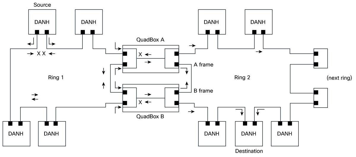
High-availability Seamless Redundancy (HSR)-HSR QuadBox is a quadruple port specialized device used to interconnect two independent HSR networks. This network redundancy feature:

  • provides enhanced protection against a failure on one QuadBox device,

  • utilizes four specific ports to bridge traffic between two HSR domains for seamless failover, and

  • ensures continuous network operation with minimal packet loss even during link or node failures.

Table 1. Feature History Table

Feature Name

Release information

Description

HSR-HSR QuadBox

26.1.1

This feature enables you to interconnect two distinct High-availability Seamless Redundancy (HSR) rings, providing continuous, fault-tolerant communication between them. This capability is crucial in industrial and critical infrastructure environments where zero packet loss and high network availability are paramount. It allows for robust network segmentation and enhanced resilience on IE3505 and IE3505H platforms.

The HSR-HSR QuadBox mode is a specialized configuration that enables the system to interconnect two independent HSR rings. This functionality explicitly supports HSR port assignments across both base and expansion modules, overriding general HSR limitations that typically restrict a system to a single HSR ring or HSR ports to base modules only.

The QuadBox connects multiple HSR rings by linking two rings through four dedicated ports without causing any learning or forwarding delays. It is designed for industrial networks that demand zero downtime, high fault tolerance, and reliability. The HSR-HSR QuadBox mode is a specialized switch configuration with fixed port assignments that vary based on the module type, ensuring seamless and efficient bridging of the two HSR rings.


Note


The interface assignment for HSR-HSR QuadBox is fixed and cannot be changed.


Table 2. Interface assignment for HSR-HSR QuadBox
Port Pair Module Ring 1 ports Ring 2 ports
Copper Base Module Gig1/4, Gig1/5 Gig1/6, Gig1/7
Mixed (SFP + Cu) Base Module Gig1/1, Gig1/2 Gig1/6, Gig1/7
SFP

Base + 8P SFP Expansion Module

Gig1/1, Gig1/2 Gig2/1, Gig2/2
Base + 8P Mixed Expansion Module Gig1/1, Gig1/2 Gig2/7, Gig2/8
Base + 16P Mixed Expansion Module Gig1/1, Gig1/2 Gig2/15, Gig2/16

The port pair option is chosen via CLI and in case of SFP, based on the expansion module attached too.

Guidelines and limitations for configuring HSR-HSR QuadBox

Activation, configuration, and management limitations and restrictions

  • Activate a new FPGA profile and reload the box to enable HSR QuadBox.

  • The feature is available in Network Essentials license.

  • When you enable HSR-HSR QuadBox mode, only the four HSR-HSR ports stay active. All other ports shut down, and their features stop working. You receive a warning for this mode change.

  • You can manage the switch through interfaces such as the device manager, CLI, or SNMP, using an in-band Switched Virtual Interface (SVI) over the HSR Ring, but expect a temporary loss of connection when you enable or disable QuadBox mode.

    So, we strongly recommend you to use a console connection when switching into or out of HSR-HSR mode.

  • Disabling HSR-HSR mode resets all physical interfaces to their default configuration and erases settings on non-QuadBox ports.

  • Set the same native VLAN on both QuadBox rings and all connected ports.

Functional limitations and restrictions

  • QuadBox disables MAC address learning.

  • When the topology has more than one QuadBox, the VLAN and multicast filter configuration must match on all the QuadBoxes and both the HSR rings.

  • HSR-HSR mode restricts switchport access.

  • HSR-HSR mode sets MTU to 2020 and you cannot change it.

  • QuadBox disables PTP.

  • HSR-HSR FPGA profile does not support show and clear commands for Node and VDAN tables, HSR ring proxyNodeTableForgetTime, HSR ring nodeforgetTime, or creation of independent HSR ring interfaces.

  • Multicast filters drop only multicast MAC addresses. They do not drop unicast MAC addresses

HSR-HSR QuadBox workflow

Summary

A HSR QuadBox, or quadruple port device, connects two HSR rings to each other. Two of these ports connect to the first ring, and the other two connect to the second ring, while any other ports on the device remain inactive.

To segregate traffic between the two rings, you can configure the QuadBox with VLAN and multicast filters. This allows you to restrict the specified VLAN and multicast groups from crossing the rings. VLAN filtering uses the VLAN allowed list to restrict VLANs. Multicast filtering matches packets with the same MAC destination address (MACDA) and optional mask as configured in the filters. If there is a match, the packets are dropped.

A QuadBox manages duplicate information. If two QuadBoxes are on the same ring and both try to send the same data from the first ring to the second, the system prevents it. If a QuadBox receives a piece of information that it has already sent, or the another QuadBox on the same ring has already sent, it recognizes the duplicate and do not forward it further. This prevents four copies to be circulated on the second ring.

The key components involved in the process are:

  • Doubly Attached Node for HSR (DANH) source node: Duplicates each outgoing frame and injects the copies into the ring in opposite directions.

  • Ring 1: Redundant path that carries the two counter-rotating frame copies and continues service even when a link is broken.

  • QuadBox A: Interconnect device that receives frames from Ring 1 and forwards a copy to Ring 2 or vice versa.

  • QuadBox B: Interconnect device that receives frames from Ring 1 and forwards a copy to Ring 2 or vice versa.

  • Ring 2: Second redundant ring that transports both frame copies (labeled as A frame and B Frame as per HSR-HSR QuadBox workflow figure) toward destination nodes and onward to the next ring if present.

  • DANH destination node: Accepts the first-arriving frame and discards the duplicate to avoid loops and duplicates.

  • Next ring: Downstream ring link that can receive forwarded traffic for extended topologies.

Workflow

Figure 1. HSR-HSR QuadBox workflow

The process involves these stages:

  1. The DANH source node sends a data frame and immediately creates two copies, injecting those copies into Ring 1 in opposite directions.
  2. The two frame copies propagate around Ring 1. If a link is broken (as indicated by the cross marks), the intact path still carries the frames to the interconnects.
  3. QuadBox A receives the Ring 1 frame traveling in one direction (clockwise) and forwards a copy to Ring 2, preserving redundancy.
  4. QuadBox B receives the Ring 1 frame traveling in the opposite direction (counter‑clockwise) and forwards a copy to Ring 2, ensuring both directions of Ring 2 carry the duplicated frames.
  5. On Ring 2, the A frame and B frame travel in opposite directions, so that all attached DANH nodes can receive at least one copy.
  6. The DANH destination node takes the first-arriving frame, processes it, and discards the second copy to prevent duplicate delivery.
  7. If the topology includes a downstream link, Ring 2 forwards traffic toward the next ring to extend connectivity.

Result

The switch provides seamless interconnection between two HSR rings, ensuring redundancy and network resilience in industrial environments.

Enable HSR-HSR QuadBox mode

You can activate HSR-HSR QuadBox mode to bridge two HSR rings using four dedicated ports on an IE3505 or IE3505H switch.

Use this task when you need to interconnect two HSR rings for redundancy.

Procedure


Step 1

Use the fpga-profile activate hsr-quadbox command to activate FPGA profile for QuadBox.

Example:

Switch# fpga-profile activate hsr-quadbox

Use the reload command to reload the device to apply the new profile.

Step 2

Use the configure terminal command to enter configuration mode.

Example:

Switch# configure terminal

Step 3

Use the hsr-hsr-mode enable pair [copper | sfp | mixed] command to enable HSR-HSR QuadBox based on the port pair option mentioned in the Interface configuration for HSR-HSR QuadBox table.

Example:

Switch(config)# hsr-hsr-mode enable pair sfp
PLEASE READ THE FOLLOWING INFORMATION ABOUT THE HSR-HSR MODE:

By enabling this mode, Ethernet ports that are not part of the feature will
no longer be operational.

When operating in this mode note the following:
        1. When this mode is configured and enabled, all other ports apart
           from the mode ports, will be shut down. Any feature running on these
           Ethernet ports will no longer function.
        2. The only means to manage the Switch will be available through the Serial Console.
        3. IP management of the Switch will be restored once "inband access via HTTP/HTTPS" 
           is configured and Device Manager will be not be accessible until inband 
           IP management is operational.

        4. Make sure Native VLAN is same on both the Quadboxes.
        5. Make sure Vlan allowed list configuration and Multicast
           filters configured are same on both quadboxes 
        6. The CLI switchport mode acess will be disabled
           when quadbox is enabled 
        7. Switchport access mode will be disabled when HSR-HSR is configured.
        8. MTU size is restricted to 2020.


ACCEPT? (yes/[no]): yes
Creating a HSR-ring interface HSR-ring 1

Creating a HSR-ring interface HSR-ring 2

Interface GigabitEthernet1/1 set to default configuration
Interface GigabitEthernet1/2 set to default configuration
Interface GigabitEthernet1/3 set to default configuration
Interface GigabitEthernet1/8 set to default configuration
Interface GigabitEthernet1/9 set to default configuration

Confirm acceptance of the mode change and acknowledge the warning about port shutdown and management changes.

Table 3. Syntax description

Keyword

Description

copper

Configures both HSR rings to use built-in copper ports.

sfp

Configures both HSR rings to use SFP ports.

mixed

Configures one HSR ring to use SFP ports and the other to use copper ports.

Refer to Interface assignment for HSR-HSR QuadBox table for additional ports information.

Step 4

(Optional) Use the hsr-ring ring_number multicast-filter deny group multicast_group_number_with_mask [ multicast_group_number_without_mask] address multicast address [mask multicast_address_mask] command to configure multicast filtering for the QuadBox.

Example:

Switch(config)# hsr-ring 1 multicast_filter_deny_group 1 0000.0100.0a00 ffff.ffff.ffff
Switch(config)# hsr-ring 2 multicast_filter_deny_group 5 0000.0100.0b00
Table 4. Syntax description

Keyword

Description

multicast_group_number_with_mask

The multicast group number configured with a mask. Configure the 48-bit multicast address and mask. The MAC destination address (MACDA) of a frame is matched with the configured 48-bit match-pattern up to the number of bits configured in the 48-bit mask. Once a match is found between the frame’s MACDA and the mask/match-pattern setting, the frame is dropped and not forwarded from the QuadBox. It ranges from 1 to 4.

multicast_group_number_without_mask

The multicast group number configured without a mask. These 256 filters allow you to specify a single group that can be blocked. Because there is no mask, each filter can block only one multicast group. Any packets with a MACDA matching the configured MAC addresses are then dropped by the QuadBox. It ranges from 5 to 260.

multicast_address_mask

The 48-bit MAC destination address written as a dotted triple of four-digit hexadecimal numbers. The ones bits in the mask are the bits to be ignored in the MAC Address.

Step 5

(Optional) Perform these steps to configure VLAN filtering for HSR ring interface 1 or 2.

  1. Use the interface hsr-ringring_number command to configure the interface for HSR ring.

    Example:

    Switch(config)# interface hsr-ring 1
  2. Use the switchport mode trunk allowed vlan vlan_num command to configure the switch mode.

    Example:

    Switch(config-if)# switchport mode trunk allowed vlan 1

    The allowed vlan_num value on the HSR ring ranges from 1 to 4096. All other VLANs are dropped.

  3. Use the exit command to exit from the configuration mode.

    Example:

    Switch(config-if)# exit

Step 6

Use the show hsr ring [multicast-filter | allowed-vlan | vlan-filter-drop-count | multicast-filter-drop] command to monitor the information.

Example:

Switch# show hsr ring multicast-filter
                HSR-ring listing:
                --------------------
HSR-ring: HS1
---------------

Filter No.  Address         Mask
=============================================
2           0000.0100.0a00 ffff.ffff.ffff

HSR-ring: HS2
---------------

Filter No.  Address         Mask
=============================================
5           0000.0100.0b00 0000.0000.0000
Switch# 
Switch# show hsr ring allowed-vlan
                HSR-ring listing:
                --------------------
HSR-ring: HS1
---------------
Vlan allowed list
----------------------
0-4094

HSR-ring: HS2
---------------
Vlan allowed list
----------------------
0-4094
Switch# show hsr ring vlan-filter-drop-count 
HSR-ring listing: 
--------------------
HSR-ring: HS1
---------------
VLAN filter drop count : 0
 HSR-ring: HS2
---------------
VLAN filter drop count : 0
Switch# show hsr ring multicast-filter-drop
                HSR-ring listing:
                --------------------
HSR-ring: HS1
---------------
Multicast filter drop count: 0
HSR-ring: HS2
---------------
Multicast filter drop count: 0
Switch# show hsr ring detail 
HSR-ring listing: 
--------------------
HSR-ring: HS1
------------
Layer type = L2 
Operation Mode = mode-H
Ports: 2	Maxports = 2
Port state = hsr-ring is In use
Protocol = Enabled  Redbox Mode = hsr-hsr  
Ports in the ring:
  1) Port: Gi1/1
   Logical slot/port = 1/1	Port state = In use 
Protocol = Enabled
  2) Port: Gi1/2
   Logical slot/port = 1/2	Port state = In use 
Protocol = Enabled
 
Ring Parameters: 
Redbox MacAddr: 9433.d845.5002
Node Forget Time: 60000 ms
Node Reboot Interval: 500 ms
Entry Forget Time: 400 ms
Proxy Node Forget Time: 60000 ms
Supervision Frame COS option: 0
Supervision Frame CFI option: 0
Supervision Frame VLAN Tag option: Disabled
Supervision Frame MacDa: 0x00
Supervision Frame VLAN id: 0
Supervision Frame Time: 3 ms
Life Check Interval: 1600 ms
Pause Time: 25 ms
fpgamode-DualUplinkEnhancement: Enabled 
 
HSR-ring: HS2
------------
Layer type = L2 
Operation Mode = mode-H
Ports: 2	Maxports = 2
Port state = hsr-ring is In use
Protocol = Enabled  Redbox Mode = hsr-hsr  
Ports in the ring:
  1) Port: Gi2/7
   Logical slot/port = 1/19	Port state = In use 
Protocol = Enabled
  2) Port: Gi2/8
   Logical slot/port = 1/20	Port state = In use 
Protocol = Enabled
 
Ring Parameters: 
Redbox MacAddr: 9433.d845.5013
Node Forget Time: 60000 ms
Node Reboot Interval: 500 ms
Entry Forget Time: 400 ms
Proxy Node Forget Time: 60000 ms
Supervision Frame COS option: 0
Supervision Frame CFI option: 0
Supervision Frame VLAN Tag option: Disabled
Supervision Frame MacDa: 0x00
Supervision Frame VLAN id: 0
Supervision Frame Time: 3 ms
Life Check Interval: 1600 ms
Pause Time: 25 ms
fpgamode-DualUplinkEnhancement: Enabled