PROFINET

Information About Configuring PROFINET

PROFINET is the leading Industrial Ethernet standard that uses TCP/IP and IT standards to connect and control machines in real time. It is widely used in industrial automation and process control networks, especially for motion control and precision instrumentation. PROFINET emphasizes fast, reliable data exchange and defines communication paths to meet different speed requirements.

Communication Levels: PROFINET communication is scalable across three levels:

  • Non-Real-Time (NRT): Uses TCP/IP with bus cycle times around 100 ms.

  • Real-Time (RT): Enables faster cycle times, approximately 10 ms.

  • Isochronous Real-Time (IRT): Achieves highly precise synchronization with cycle times as low as 1 ms (not supported in Class B).

PROFINET I/O System: PROFINET I/O is a flexible communication framework for distributed automation. It uses cyclic data transfer to exchange information, alarms, and diagnostics between controllers, I/O devices, and automation systems like motion controllers.

PROFINET Conformance Class B Support

All Cisco IE switches support PROFINET Conformance Class B.

Conformance Classes: PROFINET has different conformance classes that define supported features.

  • Class B: Common in factory automation, it supports fast, real-time communication and diagnostics — ideal for applications like production lines and equipment monitoring. Class B includes PROFINET Real Time (RT), which prioritizes important data to reduce delays, with cycle times around 10 ms. This makes RT suitable for tasks like conveyor belt and packaging machine control. However, the switches do not support Isochronous Real Time (IRT), which is required for ultra-precise synchronization.

PROFINET Device Roles

An I/O controller is a programmable logic controller (PLC) that controls I/O devices and exchanges data such as configuration, alarms, and I/O data through an automation program. The I/O controller and the I/O supervisor exchange diagnostic information. The I/O controller shares configuration and I/O information with an I/O device and receives alarms from the I/O device.

There are three main types of I/O devices:

  • I/O Devices: Field devices connected to controllers.

  • I/O Controllers: Manage and control field devices.

  • I/O Supervisors: Tools for diagnostics and configuration.
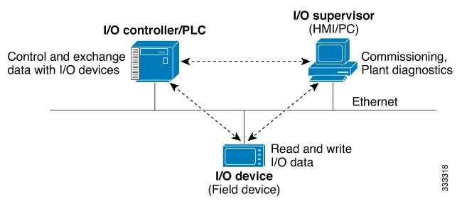
Figure 1. PROFINET Device Roles

PROFINET is designed to serve as the sole or primary management system platform for industrial networks. It streamlines device configuration and communication, reducing the need for manual setup.

Automatic Device Detection and Configuration:The I/O controller automatically detects switches using the Discovery and Configuration Protocol (DCP). It sets the device name and IP address, so you don’t need to enter Cisco IOS commands for basic configurations.

Advanced Configuration with Cisco IOS: For advanced features, like Quality of Service (QoS), DHCP, and similar capabilities, you’ll need to configure the switch using Cisco IOS commands. These advanced settings cannot be managed directly through PROFINET.

An I/O supervisor is an engineering station, such as a human machine interface (HMI) or PC, used for commissioning, monitoring, and diagnostic analysis. The I/O supervisor exchanges diagnostic, status, control, and parameter information with the I/O device.

An I/O device is a distributed I/O device such as a sensor, an actuator, or a motion controller.


Note


If Profinet DCP cannot detect the switch, PLC, or IO mac addresses, temporarily disable the firewall or virus scan from the Windows PC that installed the Siemens STEP7 or TIA Portal Automation application.


In a PROFINET I/O system, all the I/O devices communicate over an Ethernet communication network to meet the automation industry requirement for bus cycle times of less than 100 ms. The network uses switches and full-duplex data exchange to avoid data collisions. The switches play the role of I/O device in PROFINET Device Roles.

PROFINET Device Data Exchange

After PROFINET uses DCP to discover devices, including the switch, the devices establish application relationships (ARs) and communication relationships (CRs). After a connection is established and information about device parameters is exchanged, I/O data is exchanged. The switch uses non-real-time CRs to exchange the data attributes listed below.

Table 1. PROFINET I/O Switch Attributes

PROFINET I/O Switch Configuration Attributes

Value or Action

Device name

Configures a name for the device.

TCP/IP

IP address, subnet mask, default gateway, and switch virtual interface (SVI).

Primary temperature alarm

Enables or disables monitoring for the specified alarm.

Secondary temperature alarm

Enables or disables monitoring for the specified alarm.

SD card alarm

Enables or disables monitoring for the specified alarm.

RPS failed alarm

Enables or disables monitoring for the redundant power supply alarm.

Note


Before enabling monitoring for the RPS failed alarm, the user must configure the command "power-supply dual" in CLI to trigger an alarm when one of the power supplies is missing or inoperable.

Relay major alarm

Enables or disables monitoring for the specified alarm.

Reset to factory

Reset to factory (Mode 2: Communication parameter) Uses the PROFINET I/O controller to reset the switch communication parameter. This action removes the Profinet device ID, IP address, and configured SNMP writable MIBs.

Relay major configuration

Specifies the type of port alarm, for example, link fault, that triggers the major relay. Any port configured with the specified alarm type can trigger the major relay.

Table 2. PROFINET I/O Port Attributes

PROFINET I/O Port Configuration Attributes

Value or Action

Speed

10, 100, 1000, or auto.

Duplex

half, full, or auto.

Port mode

access or trunk.

Link status

shut down or no shut down.

Configure rate limiting

Broadcast, unicast, or multicast threshold exceeds configured levels.

Port link fault alarm

Enables or disables monitoring for specified alarm.

Port not forwarding alarm

Enables or disables monitoring for specified alarm.

Port not operating alarm

Enables or disables monitoring for specified alarm.

Port FCS threshold alarm

Enables or disables monitoring for specified alarm.

General Station Description File

PROFINET devices are integrated by using a general station description (GSD) file that contains the data for engineering and data exchange between the I/O controller, the I/O supervisor, and the I/O devices, including the switch. Each PROFINET I/O field device must have an associated GSD file that describes the properties of the device and contains all this information required for configuration:

  • Device identification information (device ID, vendor ID and name, product family, number of ports)

  • Number and types of pluggable modules

  • Error text for diagnostic information

  • Communication parameters for I/O devices, including the minimum cycle time, the reduction ratio, and the watch dog time

  • Configuration data for the I/O device modules, including speed, duplex, VLAN, port security information, alarms, and broadcast rate limiting thresholds

  • Parameters configured for I/O device modules for the attributes listed above

The PROFINET GSD file is bundled with the Cisco IOS release. After the switch boots at least one time, the GSD files for the switch are located in a directory called ProfinetGSD. In this directory, there is a zip file containing all the GSDs for all Cisco IE3500 Series Switch SKUs. The file is called CISCO_product_id.zip, for example, CISCO_IE35xx.zip.

The GSD file is in the switch and the I/O supervisor uses this file to manage the switch. For IOS XE-based platforms, the GSD file can be found in the Flash: or SDFlash: file system. If you want to load the GSD file for the Cisco IOS XE platform into the I/O supervisor, you need to copy it from the switch.


Note


You must use the GSD file that is associated with the Cisco IOS release on the switch to manage your PROFINET network. Both the I/O supervisor and the Cisco IOS software alert you to a mismatch between the GSD file and the switch's Cisco IOS software version.

The status of GSD match or mismatch can be determined using the show profinet status command.


Configuring PROFINET

You can use either the SIMATIC STEP7 or TIA Portal Automation application on the I/O supervisor, or you can use the Cisco IOS software to configure PROFINET on the switch.

After you enable PROFINET, Link Layer Discovery Protocol (LLDP) is automatically enabled on the switch because PROFINET relies on LLDP to fully function. If you disable PROFINET, you can enable or disable LLDP as needed.

Table 3. Feature history table

Feature

Release information

Feature description

VLAN 0 Priority Tagging

Release 17.18.1

This feature enables prioritization of critical traffic using 802.1Q frames with a VLAN ID of zero, ensuring higher processing priority without VLAN assignment.

VLAN 0 priority tagging

You can prioritize traffic without assigning it to a specific VLAN.

Starting with Cisco IOS XE Release 17.18.1, the VLAN 0 priority tagging feature allows you to prioritize traffic without assigning it to a specific VLAN. This feature enables the transmission and reception of 802.1Q Ethernet frames with the VLAN ID set to zero, by retaining the 802.1P priority bits of the VLAN 0 Ethernet packets. These Ethernet frames are known as priority tagged frames. As a result, critical traffic receives higher processing priority.

Perform these steps to configure the default PROFINET settings on a switch:

Procedure


Step 1

Use the configure terminal command to enter global configuration mode.

Example:

Switch# configure terminal

Step 2

Use the interface vlan 1 command to access the VLAN 1 interface.

Example:

Switch(config)# interface vlan 1

Step 3

Use the no shut command to enable VLAN 1.

Example:

Switch(config-if)# no shut

Step 4

Use the end command to exit the configuration mode.

Example:

Switch(config-if)#end

Step 5

To enable PROFINET on the switch, refer to Enable PROFINET.

Note


Cisco devices undergo the Profinet Certification process to ensure compliance with industrial automation standards. During this process, the use of non-standard protocols such as CDP results in test failures, preventing certification. As a result, Cisco devices intended for Profinet environments must use IEEE standard LLDP instead of CDP.


Enabling PROFINET

To enable PROFINET, follow these steps:

Procedure


Step 1

Enter global configuration mode:

Switch# configure terminal

Step 2

Enable PROFINET on the switch:

Switch(config)# profinet

After PROFINET is enabled, you can configure the device as described in Configuring the Switch with STEP7/TIA (recommended) or by using the Cisco IOS commands provided in the subsequent steps.

Step 3

(Optional) Set the PROFINET device identifier (ID) by using the Cisco IOS software:

Switch(config)# profinet id line

The maximum length of the ID string can be 240 characters. The only special characters allowed are period (.) and hyphen (-), and they are allowed only in specific positions within the ID string. The ID can have multiple labels within the string. Each label can be from 1 to 63 characters, and labels must be separated by a period (.). The final character in the string must not be zero (0).

For more details about configuring the PROFINET ID, see the PROFINET specification, document number TC2-06-0007a, filename PN-AL-protocol_2722_V22_Oct07, available at PROFIBUS.

This step is optional and can be done through STEP7 or TIA PORTAL STEP 7 or the TIA Portal Automation application installed on the Supervisor (recommended).

Step 4

(Optional) Change the VLAN number. The default VLAN number is 1. The VLAN ID range is from 1 to 4096. One PROFINET VLAN is supported per switch.

Switch(config)# profinet vlan vlan_id

Note


You must create a VLAN before assigning a new VLAN to PROFINET if you are using a nondefault VLAN.

Step 5

Return to privileged EXEC mode:

Switch(config)# end 

Step 6

Verify your entries:

Switch# show running-config

Step 7

(Optional) Save your entries in the configuration file:

Switch# copy running-config startup-config

Configuring the Switch with STEP7/TIA

Complete the following steps to configure the switch with STEP7/TIA. TIA v15.1 is used in the following example. Ensure that you do not use the CLI to configure or modify the switch configuration when PROFINET and TIA are in use.

Procedure


Step 1

Check the availability of the GSD file on the switch. You must use the same version that matches the GSD file bundled with the Cisco IOS release image.

See General Station Description File for more information.

Step 2

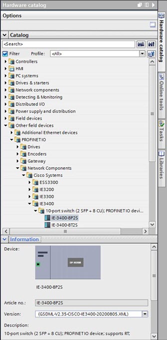
Install the GSD file in STEP7/ TIA:

  1. In STEP7/TIA, choose Options > Manage general stations description files, and browse to the location of the GSD file on the PC through source path.

    The tool displays all the available GSD files.

  2. Check the check box adjacent to the appropriate the desired GSD file and click Install.

Step 3

After the installation is completed, give it a few seconds to update the Hardware catalog. Add the switch from the Hardware catalog:

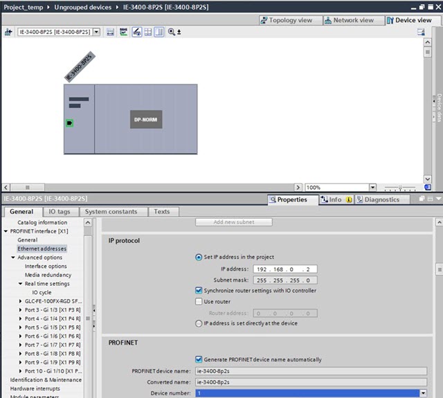
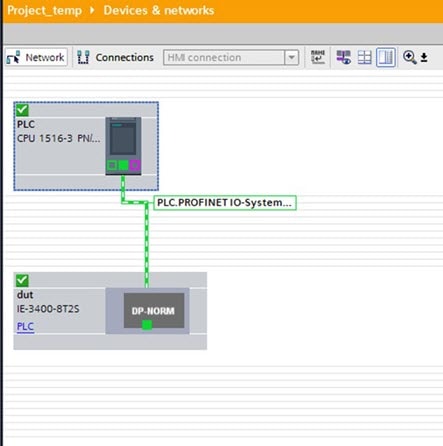
  1. In the Device view, configure IP address and PROFINET device name and save the configuration. These settings are for STEP7/TIA only; the switch is actually configured later during discovery steps.

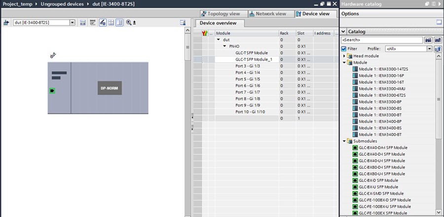
  2. Configure the required expansion module or pluggable modules in Device view.

Step 4

After the device is added in the program, discover the device through the interface of the PC connected to the PROFINET topology.

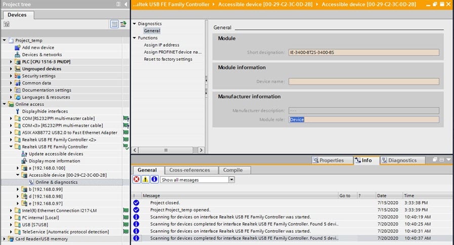
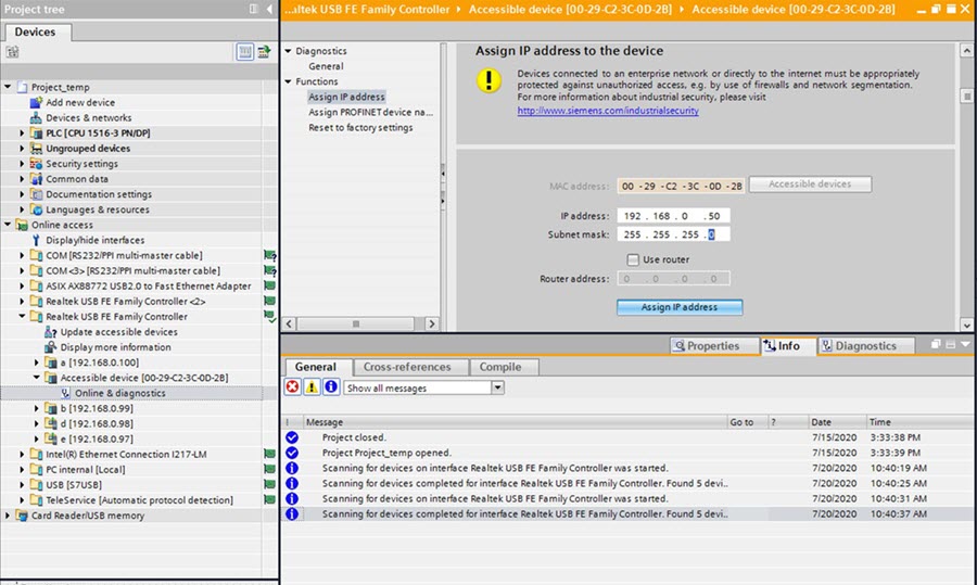
Topology discovery uses LLDP for discovery. LLDP is enabled by default on the switch. You will see the new device listed as Accessible device followed by the MAC address under the network card of the PC.

In the Devices pane on the left, under Online access, find the PC network card and click Update accessible device. This initiates the discovery of all the devices in the network.

Step 5

In the Devices pane, expand the Accessible device folder, and click Online & diagnostics to further configure the device.

  1. In the IP address field, enter the IP address and click Assign IP address to push the IP address configuration to the switch.

  2. In the PROFINET device name field, enter the device name and click Assign name to push the device name configuration to the switch.

Step 6

Download the project from STEP7/TIA and go online.

  1. Compile, download, and load the project to the PLC (I/O Controller).

  2. Go online.


PROFINET Subsystem

The switch enables the PROFINET subsystem. By default, the switch automatically configures its interfaces to manage PROFINET frames with priority tagging. When the IOSd detects PROFINET traffic, it automatically applies the configuration at runtime, using the switchport voice vlan dot1p command on each active interface. This runtime configuration ensures the switch receives the priority-tagged PROFINET frames from the LAN.

!
interface GigabitEthernet1/1
switchport voice vlan dot1p
!

Profinet connection configuration

When a Profinet connection/session is established, the network device automatically applies and saves the CLI configurations (including SNMP) given in the table below.

Table 4. CLI for the PROFINET Configuration

CLI

Purpose

snmp-server community private RW

snmp-server community public RO

Configure two Simple Network Management Protocol (SNMP) community strings, each with a read-write and read-only access.

LLDP

lldp timer 5

lldp holdtime 20

lldp run

Enable the Link Layer Discovery Protocol (LLDP) with a frame transmission interval of 5 seconds and a holdtime of 20 seconds.

CDP

no cdp run

Disable the Cisco Discovery Protocol (CDP).

Power-supply

power-supply dual

Set up the device to manage dual power supplies, ensuring it can operate redundantly if one power supply fails.

Preventing Default Gateway and CDP Loss During Reloads and Upgrades

Cisco IE switches have Profinet (PN) enabled by default to facilitate management through the Siemens TIA application portal, similar to other I/O devices, Programmable Logic Controllers (PLCs), and I/O devices within the Local Area Network (LAN).

Upon reloading an Industrial Ethernet (IE) switch operating on Cisco IOS XE 17.x or performing an upgrade from version 16.x, you may experience unexpected network connectivity disruptions. This phenomenon arises because the default gateway configuration fails to persist in the running configuration, resulting in its silent disappearance. Moreover, the Cisco Discovery Protocol (CDP) may also be disabled during this process. To rectify the loss of default gateway and CDP configurations, see the Recommended Solution section. While both the default gateway and CDP configurations are retained in the startup configuration, they do not appear in the running configuration post-reload or upgrade.

Technical Evaluation

When the Profinet feature is active, the Profinet subsystem conducts several critical checks to ensure proper configuration:

  • Non-Zero Values: The switch IP address configured on the Profinet VLAN, gateway address, and netmask must all be non-zero.

  • Subnet Consistency: The IP address and gateway address must reside within the same subnet.

  • Uniqueness: The IP address and gateway address must not be identical.

If any of these conditions are not met while the Profinet feature is enabled, the default gateway configuration is removed from the running configuration. Additionally, if you save this incomplete configuration to the startup configuration using the write mem command, the erroneous settings will persist through power cycles.

Recommended Solution

To rectify the loss of default gateway and CDP configurations, execute the following steps:

  1. Disable Profinet.

    Enter the no profinet command to disable the Profinet feature.

  2. Reconfigure settings.

    Manually re-enter the CDP and default gateway configurations.

  3. Save configuration.

    Use the write mem command to save the updated configuration.

  4. Verify configuration.

    Optionally, reload the switch to confirm that the configurations are correctly reflected in the running configuration post-reload.

  5. Check Profinet status.

    Use the show profinet status to ensure that Profinet is disabled.

Monitoring and Maintaining PROFINET

Table 5. Commands for Displaying the PROFINET Configuration

Command

Purpose

show profinet alarm

Displays all the alarms supported by PROFINET.

show profinet lldp

Displays whether LLDP is active or inactive on the ports.

show profinet sessions

Displays the currently connected PROFINET sessions.

show profinet status

Displays the status of the PROFINET subsystem.

Show profinet mrp ring 1

Displays the status of the MRP ring.

show lldp neighbor interface interface_number detail

Displays information about the adjacent interface.

The following example displays the PROFINET status and currently connected PROFINET sessions.

Switch#sh profinet status
Profinet                        : Enabled
Connection Status               : Connected
Vlan                            : 1
Profinet ID                     : dut
GSD version                     : Match
Reduct Ratio                    : 128
MRP                             : Enabled
MRP License Status              : Active
MRP Max Rings Allowed           : 3 

Switch#sh profinet session
Session #1
----------
Connected: Yes
Number Of IO CR's: 2
Number Of DiffModules: 0

Session #2
----------
Connected: No
Number Of IO CR's: 0
Number Of DiffModules: 2

Session #3
----------
Connected: No
Number Of IO CR's: 0
Number Of DiffModules: 0

Session #4
----------
Connected: No
Number Of IO CR's: 0
Number Of DiffModules: 0
**************************
Mode = Standard Mode

Monitoring Configuration Changes in PROFINET Sub-Systems

The PROFINET sub-system operates in real-time and adjusts the configuration of the device based on provisions made by remote engineering tools such as TIA Portal or in response to incoming network traffic. These dynamic updates to the running configuration often occur without your awareness. As a result, this can potentially lead to unexpected changes in system behavior.

To enhance user awareness and system transparency, syslog messages are generated whenever modifications occur in critical configuration fields. By monitoring these syslog messages, you can stay informed about real-time changes to the system configuration, ensuring better management and understanding of the PROFINET environment.

The following fields or protocols generate syslogs:

  • Link Layer Discovery Protocol (LLDP)

  • Cisco Discovery Protocol (CDP)

  • Simple Network Management Protocol (SNMP)

  • IP address and gateway configurations

Example of the syslog messages:

*Jun 19 14:41:11.247: %PROFINET_MODULE-6-PN_RUNNING_CONFIG: IP / netmask: persistent configuration applied
*Jun 19 14:41:11.248: %PROFINET_MODULE-6-PN_RUNNING_CONFIG: Gateway IP criteria met, configuring default gateway
*Jun 19 14:41:11.260: %SYS-5-CONFIG_I: Configured from console by vty0
*Jun 19 14:41:11.260: %PROFINET_MODULE-6-PN_RUNNING_CONFIG: CDP Global: service stopped
*Jun 19 14:41:11.276: %SYS-5-CONFIG_I: Configured from console by vty0
*Jun 19 14:41:11.280: %SYS-5-CONFIG_I: Configured from console by vty0
*Jun 19 14:41:11.280: %PROFINET_MODULE-6-PN_RUNNING_CONFIG: SNMP Global: service started
%PROFINET_MODULE-6-PN_RUNNING_CONFIG: LLDP Global: Tx Freq = 5 secs & Holdtime = 20 secs
*Jun 19 14:41:44.283: %PROFINET_MODULE-6-PN_RUNNING_CONFIG: Applying dot1p config on one or more interfaces

Troubleshooting PROFINET

The PLC has LEDs that display red for alarms. The I/O supervisor software monitors those alarms.

To troubleshoot PROFINET, use the debug profinet privileged EXEC command with the keywords listed in the following table.


Caution


Be aware that the output of a debug command might cause a Telnet connection to fail due to long debug outputs. When you use this command, use the serial or console port rather than Telnet using Ethernet to access the Cisco IOS CLI. You should use these commands only under the guidance of a Cisco Technical Support engineer.


Table 6. Commands for Troubleshooting the PROFINET Configuration

Command

Purpose

debug profinet alarm

Displays the alarm status (on or off) and content of the PROFINET alarms.

debug profinet cyclic

Displays information about the time-cycle-based PROFINET Ethernet frames.

debug profinet error

Displays the PROFINET session errors.

debug profinet packet ethernet

Displays information about the PROFINET Ethernet packets.

debug profinet packet udp

Displays information about the PROFINET Upper Layer Data Protocol (UDP) packets.

debug profinet platform

Displays information about the interaction between the Cisco IOS software and PROFINET.

debug profinet topology

Displays the PROFINET topology packets received.

debug profinet trace

Displays a group of traced debug output logs.

PROFINET system redundancy

A PROFINET system redundancy is a communication architecture that

  • allows IO devices and IO controllers to maintain communication in the event of device or connection failure, and

  • ensures higher availability and reliability in industrial automation networks.

Starting from 26.1.1, Cisco Industrial Ethernet (IE) switches support only S2 controller redundancy as per the PN-AL-Protocol_2722_V24MU5 and PN-AL-Services_2712_V24Mu5 specifications.


Note


After you upgrade the software, download and install the updated Generic Station Description Markup Language (GSDML) configuration files to enable S2 redundancy.


Prerequisites to PROFINET system Reduncandy modes opration

  • Enable S2 mode so that each PROFINET device forms two communication relationships (Application Relationships (ARs)) with two controllers.

  • Ensure both the IO device and the controllers support S2 redundancy features.

  • Ensure that the device is connected to both controllers through a single PROFINET interface (NAP).

  • Maintain only one active controller connection at a time.

Restrictions for PROFINET system redundancy

  • Only S2 PROFINET redudandcy is supported. R1 and R2 PROFINET redudandcy modes are not supported.

How PROFINET system redundancy modes work

Summary

PROFINET system redundancy modes ensure continuous communication between IO controllers and IO devices. This increases system availability by enabling failover paths if a controller or network component fails.

Table 7. key components of PROFINET system redundancy workflflow

Component

Function

PLC (Programmable Logic Controller)

Acts as the IO controller, managing the communication and control logic for the automation system.

IO device (IOD)

The field device (such as ET 200SP, Cisco IE switches) that connects to the controller and exchanges process data.

Network Access Point (NAP)

The PROFINET interface on the IO device, which may be single or provide redundancy.

Application Relationship (AR)

The logical connection for data exchange between a controller and an IO device.

Workflow

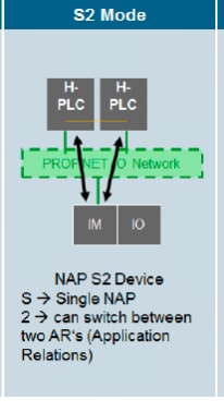
Figure 2. PROFINET system redundancy in S2 mode

The process involves these stages:

  1. The IO device supports two ARs, each with a separate PLC, but has only a single NAP.
  2. Only one AR is active for IO data exchange and the other AR is in standby.
  3. If the primary connection fails, the IO device quickly switches to the backup AR, minimizing downtime.

Result

PROFINET system redundancy modes provide graded levels of redundancy to maintain process continuity in industrial networks. These modes range from no failover (S1 redundancy mode) to controller failover (S2 redundancy mode).

Feature history for PROFINET System Redundancy

Table 8. Feature history

Feature Name

Releases

Description

PROFINET system redundancy

Cisco IOS XE 26.1.1

This feature enables Cisco Industrial Ethernet (IE) switches to interoperate with existing high available systems by providing robust controller failover using PROFINET S2 controller redundancy mode. It aims to minimize potential issues and downtime in the event of network or controller failures.

Read-only PROFINET

The read-only PROFINET feature is a configuration mode that prevents modifications to critical network parameters, including IP address, subnet mask, gateway, device name, and factory reset settings. While write operations are restricted, the feature still allows read and identification functions. Additionally, it preserves existing configurations for LLDP, SNMP, and CDP, ensuring these services remain fully operational.

Configure read-only PROFINET

Enable read-only PROFINET.

Procedure


Step 1

Use the configure terminal command to enter configuration mode.

Example:

Switch# configure terminal

Step 2

Use the profinet read-only command to enable PROFINET as read-only.

Example:

Switch(config)# profinet read-only 

Use the no profinet read-only command to disable this feature.

Step 3

(Optional) Use the Show profinet status command to monitor PROFINET status.

Example:

Switch# show profinet status 
Profinet                        : Enabled
Connection Status               : Disconnected
Vlan                            : 1
Profinet ID                     : 
GSD version                     : Unknown
Reduct Ratio                    : 128
MRP                             : Enabled
MRP License Status              : Not Applicable
MRP Max Rings Allowed           : 3
Profinet read-only              : Enabled

Feature history for Read-only PROFINET

Table 9. Feature history

Feature Name

Releases

Description

Read-only PROFINET

Cisco IOS XE 26.1.1

This feature increases device security and network flexibility by placing Discovery and Configuration Protocol (DCP) operations in read‑only mode. It:

  • Protects the IP address, gateway, and device name from changes.

  • Protects critical network settings and prevents unexpected loss of connectivity.

  • Maintains compatibility with LLDP, SNMP, and CDP.

  • Allows devices to perform identification and basic network discovery.