Resilient Ethernet Protocol

Resilient Ethernet Protocol

Resilient Ethernet Protocol (REP) is a Cisco proprietary protocol that provides an alternative to Spanning Tree Protocol (STP) to control network loops, handle link failures, and improve convergence time. REP controls a group of ports that are connected in a segment, ensures that the segment does not create any bridging loops, and responds to link failures within the segment. REP provides a basis for constructing more complex networks and supports VLAN load balancing.

REP segment is a chain of ports that are connected to each other and configured with a segment ID. Each segment consists of standard (nonedge) segment ports and two user-configured edge ports. A switch can have no more than two ports that belong to the same segment, and each segment port can have only one external neighbor. A segment can go through a shared medium, but on any link, only two ports can belong to the same segment. REP is supported only on Trunk ports.

The following figure shows an example of a segment consisting of six ports spread across four switches. Ports E1 and E2 are configured as edge ports. When all ports are operational (as in the segment on the left), a single port is blocked, shown by the diagonal line. This blocked port is also known as the Alternate port (ALT port). When there is a failure in the network, the blocked port returns to the forwarding state to minimize network disruption.

Figure 1. REP Open Segment

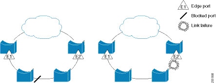
The segment shown in the preceding figure is an open segment; there is no connectivity between the two edge ports. The REP segment cannot cause a bridging loop, and you can safely connect the segment edges to any network. All hosts connected to switches inside the segment have two possible connections to the rest of the network through the edge ports, but only one connection is accessible at any time. If a failure occurs on any segment or on any port on a REP segment, REP unblocks the ALT port to ensure that connectivity is available through the other gateway.

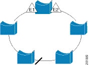
The segment in the following figure is a closed segment, also known as Ring Segment, with both edge ports located on the same router. With this configuration, you can create a redundant connection between any two routers in the segment.

Figure 2. REP Ring Segment

REP segments have the following characteristics:

  • If all ports in a segment are operational, one port (referred to as the ALT port) is in the blocked state for each VLAN. If VLAN load balancing is configured, two ALT ports in the segment control the blocked state of VLANs.

  • If a port is not operational, and causes a link failure, all ports forward traffic on all VLANs to ensure connectivity.

  • In case of a link failure, alternate ports are unblocked as quickly as possible. When the failed link is restored, a logically blocked port per VLAN is selected with minimal disruption to the network.

You can construct almost any type of network that is based on REP segments.

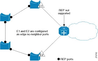
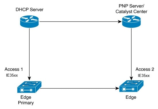
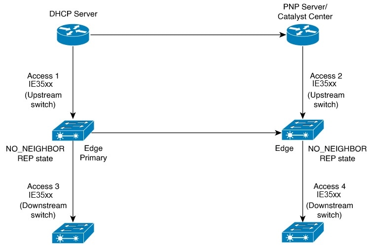
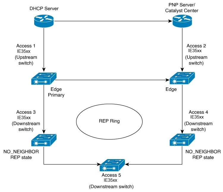
In access ring topologies, the neighboring switch might not support REP as shown in the following figure. In this case, you can configure the non-REP facing ports (E1 and E2) as edge no-neighbor ports. The edge no-neighbor port can be configured to send an STP topology change notice (TCN) towards the aggregation switch.

Figure 3. Edge No-Neighbor Ports

REP has these limitations:

  • You must configure each segment port; an incorrect configuration can cause forwarding loops in the networks.

  • REP can manage only a single failed port within the segment; multiple port failures within the REP segment cause loss of network connectivity.

  • You should configure REP only in networks with redundancy. Configuring REP in a network without redundancy causes loss of connectivity.

Link Integrity

REP does not use an end-to-end polling function between edge ports to verify link integrity. It implements local link failure detection. The REP Link Status Layer (LSL) detects its REP-aware neighbor and establishes connectivity within the segment. All the VLANs are blocked on an interface until the neighbor is detected. After the neighbor is identified, REP determines which neighbor port should become the alternate port and which ports should forward traffic.

Each port in a segment has a unique port ID. The port ID format is similar to that used by the spanning tree algorithm: a port number (unique on the bridge) associated to a MAC address (unique in the network). When a segment port is coming up, its LSL starts sending packets that include the segment ID and the port ID. The port is declared as operational after it performs a three-way handshake with a neighbor in the same segment.

A segment port does not become operational if:

  • No neighbor has the same segment ID.

  • More than one neighbor has the same segment ID.

  • A neighbor does not acknowledge a local port as a peer.

Each port creates an adjacency with its immediate neighbor. After the neighbor adjacencies are created, the ports negotiate with each other to determine the blocked port for the segment, which will function as the alternate port. All the other ports become unblocked. By default, REP packets are sent to a bridge protocol data unit-class MAC address. The packets can also be sent to a Cisco multicast address, which is used only to send blocked port advertisement (BPA) messages when there is a failure in the segment. The packets are dropped by the devices not running REP.

Fast Convergence

REP runs on a physical link basis and not on a per-VLAN basis. Only one hello message is required for all the VLANs, and this reduces the load on the protocol. We recommend that you create VLANs consistently on all the switches in a given segment and configure the same allowed VLANs on the REP trunk ports. To avoid the delay introduced by relaying messages in software, REP also allows some packets to be flooded to a regular multicast address. These messages operate at the hardware flood layer (HFL) and are flooded to the entire network, not just the REP segment. Switches that do not belong to the segment treat them as data traffic. You can control flooding of these messages by configuring an administrative VLAN for the entire domain or for a particular segment.

VLAN Load Balancing

One edge port in the REP segment acts as the primary edge port; and another as the secondary edge port. It is the primary edge port that always participates in VLAN load balancing in the segment. REP VLAN balancing is achieved by blocking some VLANs at a configured alternate port and all the other VLANs at the primary edge port. When you configure VLAN load balancing, you can specify the alternate port in one of three ways:

  • By entering the port ID of the interface. To identify the port ID of a port in the segment, enter the show interface rep detail interface configuration command for the port.

  • By entering the preferred keyword to select the port that you previously configured as the preferred alternate port with the rep segment segment-id preferred interface configuration command.

  • By entering the neighbor offset number of a port in the segment, which identifies the downstream neighbor port of an edge port. The neighbor offset number range is –256 to +256; a value of 0 is invalid. The primary edge port has an offset number of 1; positive numbers above 1 identify downstream neighbors of the primary edge port. Negative numbers indicate the secondary edge port (offset number -1) and its downstream neighbors.


    Note


    Configure offset numbers on the primary edge port by identifying a port’s downstream position from the primary (or secondary) edge port. Never enter an offset value of 1 because that is the offset number of the primary edge port.


    The following figure shows neighbor offset numbers for a segment, where E1 is the primary edge port and E2 is the secondary edge port. The red numbers inside the ring are numbers offset from the primary edge port; the black numbers outside of the ring show the offset numbers from the secondary edge port. Note that you can identify all the ports (except the primary edge port) by either a positive offset number (downstream position from the primary edge port) or a negative offset number (downstream position from the secondary edge port). If E2 became the primary edge port, its offset number would then be 1 and E1 would be -1.

    Figure 4. Neighbor Offset Numbers in a Segment

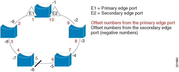
When the REP segment is complete, all the VLANs are blocked. When you configure VLAN load balancing, you must also configure triggers in one of two ways:

  • Manually trigger VLAN load balancing at any time by entering the rep preempt segment segment-id privileged EXEC command on the switch that has the primary edge port.

  • Configure a preempt delay time by entering the rep preempt delay seconds interface configuration command. After a link failure and recovery, VLAN load balancing begins after the configured preemption time period elapses. Note that the delay timer restarts if another port fails before the time has elapsed.


Note


When VLAN load balancing is configured, it does not start working until triggered by either manual intervention or a link failure and recovery.


When VLAN load balancing is triggered, the primary edge port sends out a message to alert all the interfaces in the segment about the preemption. When the secondary port receives the message, the message is sent to the network to notify the alternate port to block the set of VLANs specified in the message and to notify the primary edge port to block the remaining VLANs.

You can also configure a particular port in the segment to block all the VLANs. Only the primary edge port initiates VLAN load balancing, which is not possible if the segment is not terminated by an edge port on each end. The primary edge port determines the local VLAN load-balancing configuration.

Reconfigure the primary edge port to reconfigure load balancing. When you change the load-balancing configuration, the primary edge port waits for the rep preempt segment command or for the configured preempt delay period after a port failure and recovery, before executing the new configuration. If you change an edge port to a regular segment port, the existing VLAN load-balancing status does not change. Configuring a new edge port might cause a new topology configuration.

Spanning Tree Interaction

REP does not interact with STP, but it can coexist. A port that belongs to a segment is removed from spanning tree control and STP BPDUs are not accepted or sent from segment ports. Therefore, STP cannot run on a REP segment.

To migrate from an STP ring configuration to REP segment configuration, begin by shutdown the interface and proceed with configuring a single port in the ring as part of the segment and continue by configuring contiguous ports to minimize the number of segments.

Each segment always contains a blocked port, so multiple segments means multiple blocked ports and a potential loss of connectivity. When the segment has been configured in both directions up to the location of the edge ports, you then configure the edge ports. After the configuration, enable or unshut the ports.

REP Ports

REP segments consist of Failed, Open, or Alternate ports:

  • A port configured as a regular segment port starts as a failed port.

  • After the neighbor adjacencies are determined, the port transitions to alternate port state, blocking all the VLANs on the interface. Blocked-port negotiations occur, and when the segment settles, one blocked port remains in the alternate role and all the other ports become open ports.

  • When link flap is triggered, only the link that is shut moves to Failed state. When the Alternate port receives the failure notification, it changes to the Open state, forwarding all the VLANs.

A regular segment port converted to an edge port, or an edge port converted to a regular segment port, does not always result in a topology change. If you convert an edge port into a regular segment port, VLAN load balancing is not implemented unless it has been configured. For VLAN load balancing, you must configure two edge ports in the segment.

A segment port that is reconfigured as a spanning tree port restarts according to the spanning tree configuration. By default, this is a designated blocking port. If PortFast is configured or if STP is disabled, the port goes into the forwarding state.

Resilient Ethernet Protocol Fast

The Resilient Ethernet Protocol (REP) Fast feature allows faster link failure detection and convergence on the switch copper Gigabit Ethernet (GE) ports.

On Fiber GE ports, link down detection time is also 10 ms, but on GE copper interfaces, the link drop detection and recovery times are between 750 ms and 350 ms. As a result, link loss and recovery can be detected a lot more quickly on GE fiber interfaces than on corresponding copper interfaces. This in turn means that the convergence time for REP is a lot higher when using GE copper interfaces.

To improve link down detection time, a beacon mechanism is implemented to trigger faster link failure detection when a REP interface is configured for REP Fast mode. The switch has two timers for each REP interface. The first timer is triggered every 3 ms to transmit the beacon frame to the neighbor node. After successful transmission and reception of the frame, both the timers are reset. If the packet is not received after the transmission, then the second timer is triggered to check the reception within 10 ms. If the packet is not received, upon the timer expiry, a link down message is sent to the switch.

REP Fast works on an individual link basis. It does not impact the REP Protocol. REP Fast requires both ends of the link to support REP Fast to work. REP Fast can be used on any interface link pair that is configured for REP, but it was created to solve an issue on Gigabit copper links. REP Fast speeds up detection of the link failure on Gigabit copper interfaces.

A switch can have a combination of REP rings and REP Fast rings, with each configured as a separate segment. REP Fast enablement does not impact REP ring size since it operates only on the pair of interfaces that are configured for it. Because REP Fast has to generate Beacon frames, only six interfaces on a single REP node can be configured for REP Fast at a time.


Note


It is recommended to not have a mix of REP and REP Fast on a single ring.


If the neighbor acknowledges and is configured for REP Fast mode, convergence occurs within 50 ms. If a neighbor switch does not support the REP Fast feature, normal REP mode must be used for link up/down detection. In this case, you must disable fast mode on both ends of the link.

For information about configuring REP Fast, see Configure REP Fast in this guide.

REP fast configuration guidelines and limitations

Follow these guidelines when configuring REP fast:

  • REP fast must be configured on all ports involved in the REP ring for proper operation.

  • REP fast segments can be fiber, copper, or a combination, enabling convergence within 50 ms from a single failure.

  • It is recommended not to mix REP and REP fast on the same ring.

  • A maximum of three REP segments can have REP Fast enabled simultaneously on a switch.

  • REP fast over EtherChannel is not supported.

  • Switch supports a maximum of 3 REP fast segments.

Configure REP Fast

Follow these steps to configure REP Fast:

Before you begin

Enable REP on the switch and configure the REP topology as described in Configuring REP.

Procedure


Step 1

Enter global configuration mode:

configure terminal

Step 2

Specify the interface and enter interface configuration mode:

interface interface-id

Step 3

Enable REP Fast:

REP fastmode

Step 4

Return to privileged exec mode:

end


Example

gigabitethernet1/1
switch(config-if)#rep seg
switch(config-if)#rep segment ?
<1-1024> Between 1 and 1024

switch(config-if)#rep segment 10
switch(config-if)#rep fastmode
switch(config)#int <interface number>
switch(config-if)#
switch(config-if)#rep ?
  fastmode       REP fastmode
switch (config-if)#rep fastmode ?
  <cr>  <cr>

switch#sh run int <interface number> 
Building configuration...

Current configuration : 89 bytes
!
interface <interface number>
 switchport mode trunk
 rep segment <segment id>
 rep fastmode 
end
switch#

switch#sh run int <interface number> 
Building configuration...

Current configuration : 89 bytes
!
interface <interface number>
 switchport mode trunk
 rep segment <segment id>
 rep fastmode 
end

REP Zero Touch Provisioning

Before a network device such as a router or a switch is deployed online and fully functional, a fair amount of manual configuration is required. Zero Touch Provisioning (ZTP) technologies automate these processes, bringing up network devices into a functional state with minimal to no manual configuration. The Cisco Network Plug and Play (PnP) and Autoinstall Day Zero solutions provide a simple, secure, unified, and integrated offering for enterprise and industrial network customers to ease device rollouts for provisioning updates to an existing network. However, PnP does not support Resilient Ethernet Protocol (REP) due to the way REP is designed. Prior to the REP ZTP feature, REP ring provisioning for Day Zero required manual intervention. The REP ZTP feature introduces a new type-length-value (TLV) extension into the REP LSL packets to support configuring REP rings with zero-touch technologies.

REP and Day Zero

In a typical switch deployment using ZTP, the switch, with no startup configuration in the NVRAM, triggers the Cisco Open Plug-n-Play (PnP) agent to initiate a DHCP discovery process. This process acquires the IP configuration required for the switch from the DHCP server. The DHCP server can be configured to insert additional information in a DHCP message using vendor specific option 43. After the DHCP server receives a DHCP DISCOVER message with option 60 and the string "cisco pnp" from the switch, the DHCP server sends the IP address or hostname of the PnP server to the requesting switch. When the switch receives the DHCP response, the PnP agent extracts the option 43 from the response to get the IP address or the hostname of the PnP server. The PnP agent on the switch then uses this IP address or hostname to communicate with the PnP server. Finally, the PnP server downloads the required Day Zero configuration to the switch to complete the provisioning.

The example shown in the following diagrams illustrates REP ring provisioning on Day Zero, prior to the introduction of REP ZTP.

Figure 5. Adding Edge Nodes to the REP Ring

Note


The DHCP Server and the PnP Server/Cisco Catalyst Center are not part of the REP ring.


The first set of nodes to be provisioned are Access 1 and Access 2 in the diagram. These are the 2 edge nodes of the REP ring. Note that PnP has configured the downlink port as primary edge on Access 1 and secondary edge on Access 2.

Figure 6. Adding Downstream Nodes
When either Access 3 or Access 4 are powered on, the REP edge primary port starts the REP protocol negotiation and discovers that the neighbor port is not a REP enabled port. (Recall that the switch will be added to the REP ring only after PnP provisioning, for which it needs to first contact the DHCP server as explained earlier.) When an upstream switch port has REP configured and a downstream switch is getting on-boarded with PnP, the REP port goes into the NO_NEIGHBOR state because it is not able to discover its REP peer. In the NO_NEIGHBOR state, REP blocks all the VLANs on that port. This means that the DHCP discovery message from the new switch on the PnP startup VLAN is dropped by the upstream switch because its REP state is NO_NEIGHBOR. The same sequence of blocked ports continues for all new switches added to the REP ring (see Access 5 in figure below).
Figure 7. NO_NEIGHBOR REP State

REP ZTP Overview

The REP ZTP enhancements require that both the upstream and the downstream switches support the feature. When the new downstream switch is powered on, it initiates PNP/autoinstall. The upstream switch's interface is configured for REP and blocks the interface to the downstream switch because the downstream switch is not REP by default (the upstream switch is in REP_NO_NEIGHBOR state).

Even though the interface on the upstream switch is blocked, it will transmit REP LSL packets to the downstream switch. This is normal. With the enhancement of the REP ZTP feature, the downstream switch will start transmitting REP LSL packets with a new TLV to inform the upstream switch that its neighbor is attempting PNP provisioning.

When the upstream switch reads this REP LSL with the new TLV, it will unblock the interface for the PNP startup VLAN only. All other VLANs for which the upstream interface is a member continue to be blocked. Because the upstream switch is forwarding packets on the PNP startup VLAN for this interface, the downstream switch can complete the PNP process.

The intent of this feature is to allow new switches to join a REP ring with no manual intervention. The interface on the upstream switch keeps the startup VLAN unblocked until the downstream switch has received its configuration and has configured its own interface for REP. If there's a failure in the PNP proccess, the interface on the upstream switch reverts to blocking on the PNP startup VLAN. If the configuration received by the downstream switch does configure the interface for REP, the upstream switch reverts to blocking the PNP startup VLAN.

The downstream behavior to transmit the REP LSL with new TLV to request the PnP startup VLAN be unblocked is the default behavior for switches with no startup configuration. For security purposes, the upstream switch must have the interface to the downstream switch explicitly enabled to put the PnP startup VLAN into unblocked state. The interface level command is rep ztp-enable. See Configuring REP ZTP.


Note


The upstream switch can be part of multiple REP rings and thereby connected to multiple downstream neighbours. The PnP startup VLAN is unblocked only on the interfaces to which the downstream switch is connected.


REP segment ID auto-discovery

A REP segment ID auto-discovery feature is a network feature that

  • automatically configures and retains segment IDs in REP segments,

  • allows switches to learn and store segment ID information through dedicated CLI commands, and

  • supports both standard REP and REP Fast protocols starting with Cisco IOS XE 26.1.x or later.

REP segment ID auto-discovery reference information

REP segment ID auto-discovery reduces manual configuration errors and supports deployments with multiple REP rings by automating segment ID assignment and retention. This feature simplifies the process of adding switches to existing REP segments or creating new ones without manual intervention.

Table 1. Feature history for REP Segment ID auto discovery

Feature name

Release

Description

REP Segment ID auto discovery

Cisco IOS XE 26.1.1

REP segment ID auto-discovery was introduced in Cisco IOS XE 26.1.x to automate segment ID configuration, reduce manual errors, and simplify deployment in REP networks.

REP segment ID auto-discovery deployment

You can configure REP Segment-ID auto-discovery when you add a switch to a REP segment or when you create a REP segment. In both situations, manual configuration is reduced.

This section explains the recommended deployment order for configuring and expanding REP segments in industrial networks.

Add new switch to an REP segment

Build new REP segment

Build a REP segment with uplinks (daisy-chain)

Add new switch to an REP segment

  • When you add a switch to an existing REP segment, use the rep autodisc command on the switches connected to the upstream and downstream devices to enable auto-discovery.

  • After connecting the new switch, the upstream and downstream switches send Cisco Discovery Protocol (CDP) packets with REP segment ID information to the new switch interfaces.

  • Use the rep segment auto command on the new switch interfaces. This action allows the interfaces to learn the segment ID.

Build new REP segment

  • When you build a closed REP segment, you must start with a static REP segment ID configuration from an edge device. The primary and secondary edge devices in a closed segment are on the same switch.

  • When you build an open REP segment, you must start a static REP segment ID configuration from both primary and secondary edge devices.

  • The remaining steps apply to both closed and open REP segments. Begin by bringing up the next node in the REP ring. Then, add a new node between the two switches to enable auto-discovery.

Build REP segment with uplinks (daisy-chain)

  • When you build a ring segment with uplinks (daisy chain), you must start with a static REP Segment ID configuration from the REP edge node. Connect the next device to one of the uplinks to the edge node and enable auto-discovery on the connected uplink. Port pairing support duplicates the REP configuration on the paired uplink port.

  • After connecting each device to the uplink, the process repeats to bring the REP segment in a daisy chain manner. Each new REP node joins the ring automatically by learning the REP Segment ID from its connected node. In an REP open ring, the last device on the segment acts as an edge device with static REP configuration.

REP segment ID auto-discovery limitations

  • If you configure a REP segment on a downlink port, the switch receives the segment ID from the upstream switch and connects the partner downlink port to the same segment. The switch does not pass the segment ID to its partner port. As a result, you must explicitly configure the partner port of the downlink pair.

  • This feature does not support the insertion of an edge node into an existing segment. Configure static or manual REP segment IDs on both the primary and secondary edge devices.

  • When inserting a new switch between two existing segment switches, connect the interface of the new switch to the corresponding interfaces on the existing switches that transmit the same segment ID. Incorrect connections cause segment failure. This requirement also applies when you remove a node between two others.

    For example, if Gi1/1 of switch1 and Gi1/2 of switch2 are part of an existing segment, and you insert switch3 between them, ensure that the interfaces connect to Gi1/1 of switch1 and Gi1/2 of switch2. This approach includes switch3 in the same segment.

  • If you configure REP automatically on an interface using the rep segment auto command, and later remove the REP configuration with the no rep segment command or overwrite it with the rep segment <> command, you cannot configure REP automatically again by using the rep segment auto command. To restore automatic configuration, shut down the interface, bring it up, and enter the rep segment auto command again.

  • REP segment ID auto-discovery depends on the CDP protocol. It does not support EtherChannel links.

Configuring Resilient Ethernet Protocol

A segment is a collection of ports that are connected to one another in a chain and configured with a segment ID. To configure REP segments, configure the REP administrative VLAN (or use the default VLAN 1) and then add the ports to the segment, using interface configuration mode. You should configure two edge ports in a segment, with one of them being the primary edge port and the other the secondary edge port by default. A segment should have only one primary edge port. If you configure two ports in a segment as primary edge ports, for example, ports on different switches, the REP selects one of them to serve as the segment's primary edge port. If necessary, you can configure the location to which segment topology change notices (STCNs) and VLAN load balancing are to be sent.

Default REP Configuration

  • REP is disabled on all the interfaces. When enabled, the interface is a regular segment port unless it is configured as an edge port.

  • When REP is enabled, the task of sending segment topology change notices (STCNs) is disabled, all the VLANs are blocked, and the administrative VLAN is VLAN 1.

  • When VLAN load balancing is enabled, the default is manual preemption with the delay timer disabled. If VLAN load balancing is not configured, the default after manual preemption is to block all the VLANs in the primary edge port.

  • REP Fast is disabled by default.

  • REP Zero Touch Provisioning is enabled by default at the global level and disabled at the interface level.

REP configuration guidelines and limitations

Follow these guidelines when configuring REP:

  • Begin by configuring one port, then contiguous ports to minimize the number of segments and blocked ports.

  • If more than two ports in a segment fail without external neighbors, one port transitions to a forwarding state to maintain connectivity.

  • In the show interfaces rep command output, failed ports show roles as Fail Logical Open and Fail No Ext Neighbor. When external neighbors are configured, ports transition through alternate states to open or remain alternate.

  • REP ports must be Layer 2 IEEE 802.1Q or trunk ports.

  • Configure all trunk ports in the segment with the same allowed VLANs.

  • Avoid enabling REP through a SSH or Telnet on the same interface used for the session, as REP blocks all VLANs until unblocked by another REP interface, risking loss of connectivity.

  • For configuration changes, shut down or disable the interface, apply changes, then enable or unshut the interface

  • REP and STP cannot run on the same segment or interface.

  • STP connections to REP segments must be at the segment edge to avoid bridging loops; all STP BPDUs are dropped at REP interfaces.

  • The rep stcn command is mandatory at REP-STP boundaries where ENN is configured to allow status change notifications.

  • On a switch, if REP is enabled on two ports, both must be either regular segment ports or edge ports:

    • Only two ports per switch can belong to the same REP segment.

    • If one port is configured, it should be an edge port.

    • Two ports in the same segment must be both edge, both regular, or one regular and one edge no-neighbor port.

    • Misconfiguration treating an edge port and regular segment port on the same switch results in the edge port being treated as regular.

  • REP interfaces start and remain blocked until safe to unblock; monitor status to avoid connection loss.

  • REP sends all LSL PDUs untagged on the native VLAN; BPA messages use the administration VLAN (default VLAN 1).

  • The rep lsl-age-timer command configures how long a REP interface stays up without receiving a hello (120 ms to 10,000 ms). The LSL hello timer is age-timer divided by three.

    • Use rep lsl-age-timer only for non-REP fast copper Gigabit interfaces.

    • EtherChannel port channels do not support values less than 1000 ms; attempts to configure lower values are rejected.

    • The rep lsl-age-timer command is intended for scenarios where normal link down detection is too slow.

  • FastEthernet and fiber connections do not require lsl-age-timer. Gigabit copper can use REP fast instead of lsl-age-timer.

  • REP ports cannot be configured as:

    • Switched Port Analyzer (SPAN) destination port

    • Tunnel port

    • Access port

  • REP is supported on EtherChannels but not on individual ports within an EtherChannel.

  • Switch supports a maximum of 26 open REP segments or 3 REP fast segments.


    Note


    To increase the number of REP segments, an expansion module can be attached to the base module.


  • REP ring size is unlimited, but rings larger than 20 nodes may not achieve desired convergence.

REP ZTP Configuration Guidelines

  • REP ZTP requires the PnP feature to be present on the switches.

  • This transient state change in port forwarding behavior in NO_NEIGHBOR state allows a DHCP request message to reach a DHCP server and unblock PnP provisioning of a new switch. There should not be any impact to the REP state machine after PnP completion.

  • The changes in REP behavior during the NO_NEIGHBOR state apply only to REP Zero Touch Provisioning (ZTP). If the PnP feature is not present, normal REP functionality should work as expected.

  • REP ZTP is supported on physical and EtherChannel interfaces.

  • REP ZTP is supported on both copper (downlink) and fiber (uplink) interfaces.

  • REP ZTP is interoperable only with other IE switching products running IOS XE that claim REP ZTP support.

Configure REP Administrative VLAN

To avoid the delay created by link-failure messages, and VLAN-blocking notifications during load balancing, REP floods packets to a regular multicast address at the hardware flood layer (HFL). These messages are flooded to the whole network, and not just the REP segment. You can control the flooding of these messages by configuring an administrative VLAN.

Follow these guidelines when configuring the REP administrative VLAN:

  • If you do not configure an administrative VLAN, the default is VLAN 1.

  • You can configure one admin VLAN on the switch for all segments.

  • The administrative VLAN cannot be the RSPAN VLAN.

To configure the REP administrative VLAN, follow these steps, beginning in privileged EXEC mode:

Procedure

  Command or Action Purpose

Step 1

enable

Example:

Device> enable

Enables privileged EXEC mode.

Enter your password if prompted.

Step 2

configure terminal

Example:

Device# configure terminal

Enters global configuration mode.

Step 3

rep admin vlan vlan-id

Example:

Device(config)# rep admin vlan 2

Specifies the administrative VLAN. The range is from 2 to 4094.

To set the admin VLAN to 1, which is the default, enter the no rep admin vlan global configuration command.

Step 4

end

Example:

Device(config)# end
Exits global configuration mode and returns to privileged EXEC mode.

Step 5

show interface [ interface-id] rep detail

Example:

Device# show interface gigabitethernet1/1 rep detail

(Optional) Verifies the configuration on a REP interface.

Step 6

copy running-config startup config

Example:

Device# copy running-config startup config

(Optional) Saves your entries in the switch startup configuration file.

Configure a REP Interface

To configure REP, enable REP on each segment interface and identify the segment ID. This task is mandatory, and must be done before other REP configurations. You must also configure a primary and secondary edge port on each segment. All the other steps are optional.

Follow these steps to enable and configure REP on an interface:

Procedure

  Command or Action Purpose

Step 1

enable

Example:

Device> enable

Enables privileged EXEC mode.

Enter your password if prompted.

Step 2

configure terminal

Example:

Device# configure terminal

Enters global configuration mode.

Step 3

interface interface-id

Example:

Device(config)# interface gigabitethernet1/1

Specifies the interface, and enters interface configuration mode. The interface can be a physical Layer 2 interface or a port channel (logical interface).

Step 4

switchport mode trunk

Example:

Device(config-if)# switchport mode trunk

Configures the interface as a Layer 2 trunk port.

Step 5

rep segment segment-id [edge [ no-neighbor] [primary ]] [preferred ]

Example:

Device(config-if)# rep segment 1 edge no-neighbor primary

Enables REP on the interface and identifies a segment number. The segment ID range is from 1 to 1024.

Note


You must configure two edge ports, including one primary edge port, for each segment.

These optional keywords are available:

  • (Optional) edge : Configures the port as an edge port. Each segment has only two edge ports. Entering the keyword edge without the keyword primary configures the port as the secondary edge port.

  • (Optional) primary : Configures the port as the primary edge port, the port on which you can configure VLAN load balancing.

  • (Optional) no-neighbor : Configures a port with no external REP neighbors as an edge port. The port inherits all the properties of an edge port, and you can configure the properties the same way you do for an edge port.

Note


Although each segment can have only one primary edge port, if you configure edge ports on two different switches and enter the keyword primary on both the switches, the configuration is valid. However, REP selects only one of these ports as the segment primary edge port. You can identify the primary edge port for a segment by entering the show rep topology command in privileged EXEC mode.

  • (Optional) preferred : Indicates that the port is the preferred alternate port or the preferred port for VLAN load balancing.

Note


Configuring a port as preferred does not guarantee that it becomes the alternate port; it merely gives the port a slight edge over equal contenders. The alternate port is usually a previously failed port.

Step 6

rep stcn {interface interface id | segment id-list | stp }

Example:

Device(config-if)# rep stcn segment 25-50
(Optional) Configures the edge port to send segment topology change notices (STCNs).
  • interface interface-id : Designates a physical interface or port channel to receive STCNs.

  • segment id-list : Identifies one or more segments to receive STCNs. The range is from 1 to 1024.

  • stp : Sends STCNs to STP networks.

Note


Spanning Tree (MST) mode is required on edge no-neighbor nodes when rep stcn stp command is configured for sending STCNs to STP networks.

Note


The incorrect configuration of STCN on the edge leads to a loop in the network topology.

Step 7

rep block port {id port-id | neighbor-offset | preferred } vlan {vlan-list | all }

Example:

Device(config-if)# rep block port id 0009001818D68700 vlan 1-100

(Optional) Configures VLAN load balancing on the primary edge port, identifies the REP alternate port in one of three ways (id port-id , neighbor_offset , preferred ), and configures the VLANs to be blocked on the alternate port.

  • id port-id : Identifies the alternate port by port ID. The port ID is automatically generated for each port in the segment. You can view interface port IDs by entering the show interface type number rep [detail ] privileged EXEC command.

  • neighbor_offset : Number to identify the alternate port as a downstream neighbor from an edge port. The range is from -256 to 256, with negative numbers indicating the downstream neighbor from the secondary edge port. A value of 0 is invalid. Enter -1 to identify the secondary edge port as the alternate port.

Note


Because you enter the rep block port command at the primary edge port (offset number 1), you cannot enter an offset value of 1 to identify an alternate port.

  • preferred : Selects the regular segment port previously identified as the preferred alternate port for VLAN load balancing.

  • vlan vlan-list : Blocks one VLAN or a range of VLANs.

  • vlan all : Blocks all the VLANs.

Note


Enter this command only on the REP primary edge port.

Step 8

rep preempt delay seconds

Example:

Device(config-if)# rep preempt delay 100

(Optional) Configures a pre-empt time delay.

  • Use this command if you want VLAN load balancing to be automatically triggered after a link failure and recovery.

  • The time delay range is between 15 to 300 seconds. The default is manual pre-emption with no time delay.

Note


Enter this command only on the REP primary edge port.

Step 9

rep lsl-age-timer value

Example:

Device(config-if)# rep lsl-age-timer 2000

(Optional) Configures a time (in milliseconds) for which the REP interface remains up without receiving a hello from a neighbor.

The range is from 120 to 10,000 ms in 40-ms increments. The default is 5000 ms (5 seconds).

Note

 
  • EtherChannel port channel interfaces do not support LSL age-timer values that are less than 1000 ms.

  • Ensure that both the ports on the link have the same LSL age configured in order to avoid link flaps.

Step 10

end

Example:

Device(config-if)# end

Exits global configuration mode and returns to privileged EXEC mode.

Step 11

show interface [ interface-id] rep [detail ]

Example:

Device# show interface gigabitethernet1/1 rep detail

(Optional) Displays the REP interface configuration.

Step 12

copy running-config startup-config

Example:

Device# copy running-config startup-config

(Optional) Saves your entries in the router startup configuration file.

Setting Manual Preemption for VLAN Load Balancing

If you do not enter the rep preempt delay seconds interface configuration command on the primary edge port to configure a preemption time delay, the default is to manually trigger VLAN load balancing on the segment. Be sure that all the other segment configurations have been completed before manually preempting VLAN load balancing. When you enter the rep preempt delay segment segment-id command, a confirmation message is displayed before the command is executed because preemption might cause network disruption.

Procedure

  Command or Action Purpose

Step 1

enable

Example:

Device> enable

Enables privileged EXEC mode.

Enter your password if prompted.

Step 2

rep preempt segment segment-id

Example:

Device# rep preempt segment 100
The command will cause a momentary traffic disruption.
Do you still want to continue? [confirm]

Manually triggers VLAN load balancing on the segment.

You need to confirm the command before it is executed.

Step 3

show rep topology segment segment-id

Example:

Device# show rep topology segment 100

(Optional) Displays REP topology information.

Step 4

end

Example:

Device# end

Exits privileged EXEC mode.

Configuring SNMP Traps for REP

You can configure a router to send REP-specific traps to notify the Simple Network Management Protocol (SNMP) server of link-operational status changes and port role changes.

Procedure

  Command or Action Purpose

Step 1

enable

Example:

Device> enable

Enables privileged EXEC mode.

Enter your password if prompted.

Step 2

configure terminal

Example:

Device# configure terminal

Enters global configuration mode.

Step 3

snmp mib rep trap-rate value

Example:

Device(config)# snmp mib rep trap-rate 500

Enables the switch to send REP traps, and sets the number of traps sent per second.

  • Enter the number of traps sent per second. The range is from 0 to 1000. The default is 0 (no limit is imposed; a trap is sent at every occurrence).

Step 4

end

Example:

Device(config)# end

Returns to privileged EXEC mode.

Step 5

show running-config

Example:

Device# show running-config

(Optional) Displays the running configuration, which can be used to verify the REP trap configuration.

Step 6

copy running-config startup-config

Example:

Device# copy running-config startup-config

(Optional) Saves your entries in the switch startup configuration file.

Configuring REP ZTP

To configure REP ZTP, you enable or disable it at the global level and the interface level. The default states are:

  • Global level: Enabled

  • Interface level: Disabled

You must explicitly enable the feature at the interface level on the upstream device interface connected to the downstream device. When enabled, only that interface will receive notification from the downstream switch to block or unblock the PnP startup VLAN.

Procedure


Step 1

Enter global configuration mode:

Switch# configure terminal

Step 2

Globally enable REP ZTP:

Switch(config)# rep ztp

Use the no form of the command to disable REP ZTP: Switch(config)# no rep ztp

Step 3

Enter interface configuration mode on the upstream device interface that is connected to the downstream device:

Switch(config)# interface <interface-name>

Step 4

Enable REP ZTP on the interface:

Switch(config-if)#rep ztp-enable

Use the no form of the command to disable REP ZTP on the interface: Switch(config-if)#no rep ztp-enable


Example

The following example shows the minimum configuration required to enable the REP ZTP feature on the upstream device interface that is connected to a downstream device.

Switch#show running-config interface gigabitEthernet 1/1
Building configuration...

Current configuration : 93 bytes
!
interface GigabitEthernet1/1
 switchport mode trunk
 rep segment 100
 rep ztp-enable 
end

Configure REP segment ID auto-discovery

Use this configuration during new REP ring deployments, ring expansions, or when you want to minimize manual configuration steps. This process simplifies and accelerates ring deployments.

Before you begin

  • Verify that your switch model and software version support REP segment ID auto-discovery.

  • Identify which devices will be configured as edge nodes (these require static configuration).

  • Ensure that CDP is enabled on all devices.

Perform these steps to configure REP segment ID auto-discovery:

Procedure


Step 1

Use the configure terminal command to enter global configuration mode.

Example:

Device# configure terminal

Step 2

Use the rep autodisc command to configure REP auto discovery.

Example:

Device(config)# rep autodisc
Use no rep autodisc command to disable the REP auto discovery.

Step 3

Use the interface interfacename interface-id command to enter the interface configuration mode.

Example:

Device(config)# interface GigabitEthernet1/3

Step 4

Use the rep segment auto command to enable auto-discovery on an interface that participates in the REP ring.

Example:

Device(config-if)# rep segment auto
Use no rep segment command to disable auto-discovery.

Step 5

Use the rep segment segment-id edge command to configure static REP on edge nodes with static REP segment ID.

Example:

Device(config-if)# rep segment 100 edge

Step 6

(Optional) Use the show interfaces rep detail command to check the status of REP segment ID auto-discovery on the segment.

Example:

This example shows that the REP segment ID auto-discovery is globally enabled on a device.

Device# show interfaces rep detail
REP Segment Id Auto Discovery Status: Enabled
This example shows that the REP segment ID auto-discovery is globally disabled on a device.
Device# show interfaces rep detail
REP Segment Id Auto Discovery Status: Disabled 

This example shows that the REP segment ID on the interface is configured automatically.

Device# show interfaces rep detail
REP Segment Id Type: Auto

This example shows that the REP segment ID on the interface is configured manually.

Device# show interfaces rep detail
REP Segment Id Type: Manual 

Monitoring Resilient Ethernet Protocol Configurations

This is an example of the output for the show interface [ interface-id] rep [ detail] command. This output shows the REP configuration and status on an uplink port.

Device# show interfaces GigabitEthernet1/1 rep detail

GigabitEthernet1/1 REP enabled
Segment-id: 3 (Primary Edge)
PortID: 03010015FA66FF80
Preferred flag: No
Operational Link Status: TWO_WAY
Current Key: 02040015FA66FF804050
Port Role: Open
Blocked VLAN: <empty>
Admin-vlan: 1
REP-ZTP Status: Disabled
Preempt Delay Timer: disabled
Configured Load-balancing Block Port: none
Configured Load-balancing Block VLAN: none
STCN Propagate to: none
LSL PDU rx: 999, tx: 652
HFL PDU rx: 0, tx: 0
BPA TLV rx: 500, tx: 4
BPA (STCN, LSL) TLV rx: 0, tx: 0
BPA (STCN, HFL) TLV rx: 0, tx: 0
EPA-ELECTION TLV rx: 6, tx: 5
EPA-COMMAND TLV rx: 0, tx: 0
EPA-INFO TLV rx: 135, tx: 136

This is an example of the output for the show interface [ interface-id] rep [ detail] command. This output shows the REP configuration and status on a downlink port.

Device#show interface GigabitEthernet1/1 rep detail
GigabitEthernet1/1   REP enabled
Segment-id: 1 (Segment)
PortID: 019B380E4D9ACAC0
Preferred flag: No
Operational Link Status: NO_NEIGHBOR
Current Key: 019B380E4D9ACAC0696B
Port Role: Fail No Ext Neighbor
Blocked VLAN: 1-4094
Admin-vlan: 1
REP-ZTP Status: Disabled
Preempt Delay Timer: 100 sec
LSL Ageout Timer: 2000 ms
LSL Ageout Retries: 5
Configured Load-balancing Block Port: 09E9380E4D9ACAC0
Configured Load-balancing Block VLAN: 1-100
STCN Propagate to: segment 25
LSL PDU rx: 292, tx: 340
HFL PDU rx: 0, tx: 0
BPA TLV rx: 0, tx: 0
BPA (STCN, LSL) TLV rx: 0, tx: 0
BPA (STCN, HFL) TLV rx: 0, tx: 0
EPA-ELECTION TLV rx: 0, tx: 0
EPA-COMMAND TLV rx: 0, tx: 0
EPA-INFO TLV rx: 0, tx: 0

This is an example for the show rep topology [ segment segment-id] [ archive ] [ detail] command. This output shows the REP topology information for all the segments.

Device# show rep topology

REP Segment 1
BridgeName       PortName     Edge Role
---------------- ----------   ---- ----
10.64.106.63     Gi1/4        Pri  Open
10.64.106.228    Gi1/4             Open
10.64.106.228    Gi1/3             Open
10.64.106.67     Gi1/3             Open
10.64.106.67     Gi1/4             Alt 
10.64.106.63     Gi1/4        Sec  Open

REP Segment 3
BridgeName       PortName     Edge Role
---------------- ----------   ---- ----
10.64.106.63     Gi1/1        Pri  Open
SVT_3400_2       Gi1/3             Open
SVT_3400_2       Gi1/4             Open
10.64.106.68     Gi1/2             Open
10.64.106.68     Gi1/1             Open
10.64.106.63     Gi1/2        Sec  Alt

Displaying REP ZTP Status

Use the show command to identify the state of REP ZTP on an interface. In the following example, the feature is disabled on interface GigabitEthernet 1/1 and it is enabled on interface GigabitEthernet 1/1. The status of pnp_startup_vlan is "Blocked".

Procedure


Step 1

In priviledged exec mode, enter:

show interfaces rep detail

Example:

GigabitEthernet1/1   REP enabled
Segment-id: 100 (Segment)
PortID: 00016C13D5AC4320
Preferred flag: No
Operational Link Status: TWO_WAY
Current Key: 00026C13D5AC43209DAB
Port Role: Open
Blocked VLAN: <empty>
Admin-vlan: 1
REP-ZTP Status: Disabled
REP Segment Id Auto Discovery Status: Enabled
REP Segment Id Type: Manual
Preempt Delay Timer: disabled
LSL Ageout Timer: 5000 ms
LSL Ageout Retries: 5
Configured Load-balancing Block Port: none
Configured Load-balancing Block VLAN: none
STCN Propagate to: none
LSL PDU rx: 382, tx: 297
HFL PDU rx: 0, tx: 0
BPA TLV rx: 1, tx: 19
BPA (STCN, LSL) TLV rx: 0, tx: 0
BPA (STCN, HFL) TLV rx: 0, tx: 0
EPA-ELECTION TLV rx: 95, tx: 0
EPA-COMMAND TLV rx: 0, tx: 0
EPA-INFO TLV rx: 95, tx: 95

GigabitEthernet1/1   REP enabled
Segment-id: 100 (Segment)
PortID: 00026C13D5AC4320
Preferred flag: No
Operational Link Status: NO_NEIGHBOR
Current Key: 00026C13D5AC43209DAB
Port Role: Fail No Ext Neighbor
Blocked VLAN: 1-4094
Admin-vlan: 1
REP-ZTP Status: Enabled
REP-ZTP PnP Status: Unknown
REP-ZTP PnP Vlan: 1
REP-ZTP Port Status: Blocked
REP Segment Id Auto Discovery Status: Enabled
REP Segment Id Type: Manual
Preempt Delay Timer: disabled
LSL Ageout Timer: 5000 ms
LSL Ageout Retries: 5
Configured Load-balancing Block Port: none
Configured Load-balancing Block VLAN: none
STCN Propagate to: none
LSL PDU rx: 11, tx: 11
HFL PDU rx: 0, tx: 0
BPA TLV rx: 0, tx: 0
BPA (STCN, LSL) TLV rx: 0, tx: 0
BPA (STCN, HFL) TLV rx: 0, tx: 0
EPA-ELECTION TLV rx: 0, tx: 0
EPA-COMMAND TLV rx: 0, tx: 0
EPA-INFO TLV rx: 0, tx: 0     

Step 2

Use the show command again to display the status of pnp_startup_vlan.

When the downstream device is booted up, it sends notification to the connected upstream switch interface to unblock the pnp_startup_vlan for it to get the DHCP IP address and further establish communication with the PNP server or Cisco Catalyst Center. The show command indicates the status as "Unblocked".

The following syslogs on the upstream switch notify you about FWD and BLK of ports. There are no syslogs in the downstream switch as PnP takes control of the console and no syslogs can be printed on the console.

REP-6-ZTPPORTFWD: Interface GigabitEthernet1/1 moved to forwarding on ZTP notification
REP-6-ZTPPORTBLK: Interface GigabitEthernet1/1 moved to blocking on ZTP notification

Example:

Switch#show interfaces rep detail                         
GigabitEthernet1/1   REP enabled
Segment-id: 100 (Segment)
PortID: 00016C13D5AC4320
Preferred flag: No
Operational Link Status: TWO_WAY
Current Key: 00026C13D5AC43209DAB
Port Role: Open
Blocked VLAN: <empty>
Admin-vlan: 1
REP-ZTP Status: Disabled
REP Segment Id Auto Discovery Status: Enabled
REP Segment Id Type: Manual
Preempt Delay Timer: disabled
LSL Ageout Timer: 5000 ms
LSL Ageout Retries: 5
Configured Load-balancing Block Port: none
Configured Load-balancing Block VLAN: none
STCN Propagate to: none
LSL PDU rx: 430, tx: 358
HFL PDU rx: 0, tx: 0
BPA TLV rx: 1, tx: 67
BPA (STCN, LSL) TLV rx: 0, tx: 0
BPA (STCN, HFL) TLV rx: 0, tx: 0
EPA-ELECTION TLV rx: 107, tx: 0
EPA-COMMAND TLV rx: 0, tx: 0
EPA-INFO TLV rx: 107, tx: 108
          
GigabitEthernet1/1   REP enabled
Segment-id: 100 (Segment)
PortID: 00026C13D5AC4320
Preferred flag: No
Operational Link Status: NO_NEIGHBOR
Current Key: 00026C13D5AC43209DAB
Port Role: Fail No Ext Neighbor
Blocked VLAN: 1-4094
Admin-vlan: 1
REP-ZTP Status: Enabled
REP-ZTP PnP Status: In-Progress
REP-ZTP PnP Vlan: 69
REP-ZTP Port Status: Unblocked
REP Segment Id Auto Discovery Status: Enabled
REP Segment Id Type: Manual
Preempt Delay Timer: disabled
LSL Ageout Timer: 5000 ms
LSL Ageout Retries: 5
Configured Load-balancing Block Port: none
Configured Load-balancing Block VLAN: none
STCN Propagate to: none
LSL PDU rx: 32, tx: 40
HFL PDU rx: 0, tx: 0
BPA TLV rx: 0, tx: 0
BPA (STCN, LSL) TLV rx: 0, tx: 0
BPA (STCN, HFL) TLV rx: 0, tx: 0
EPA-ELECTION TLV rx: 0, tx: 0
EPA-COMMAND TLV rx: 0, tx: 0
EPA-INFO TLV rx: 0, tx: 0

Step 3

Use the show platform hardware fed switch active vlan vlan-id command to check the interface state of the PnP startup VLAN:

Example:

Switch#show platform hardware fed switch active vlan 901
vlan id is:: 901
Interfaces in forwarding state: : Gig1/1(Untagged), Gig1/2(Untagged)
flood list: : Gig1/1, Gig1/2

Step 4

(Optional) Use the following debug commands to troubleshoot REP ZTP:

  • debug rep lslsm: This command helps you understand LSL state machine events in the NO_NEIGHBOR state.

  • debug rep packet: Use this command to dump LSL packets with the REP ZTP LSL TLV to check the PnP status on the peer client node.