Wireless RF Reference Guide
Available Languages
Bias-Free Language
The documentation set for this product strives to use bias-free language. For the purposes of this documentation set, bias-free is defined as language that does not imply discrimination based on age, disability, gender, racial identity, ethnic identity, sexual orientation, socioeconomic status, and intersectionality. Exceptions may be present in the documentation due to language that is hardcoded in the user interfaces of the product software, language used based on RFP documentation, or language that is used by a referenced third-party product. Learn more about how Cisco is using Inclusive Language.
- US/Canada 800-553-2447
- Worldwide Support Phone Numbers
- All Tools
 Feedback
 Feedback
This document is hardware focused and serves as an update to be used with Cisco’s existing Wi-Fi deployment guides and best practices.
This document is an RF reference design guide. It provides an updated overview of all the various Cisco® and Meraki® products and technologies currently available. It focuses primarily on hardware and RF technologies that operate under the Wi-Fi 6 and 6E standards but also covers several RF fundamentals and technologies, such as self-identifying (smart) antennas and other aspects unique to different access point models. This guide is in addition to the many WLAN deployment guides already posted.
At the back of this guide you will find a list of deployment guides and other resources that you should find helpful.
Understanding Wi-Fi history: IEEE and the Wi-Fi Alliance
RF capabilities within each access point, such as channel bonding, data rates, multiple spatial streams, maximum link rates and frequencies used, etc., are defined by the IEEE in what is known as the 802.11 specification and are listed in the data sheet for each access point.
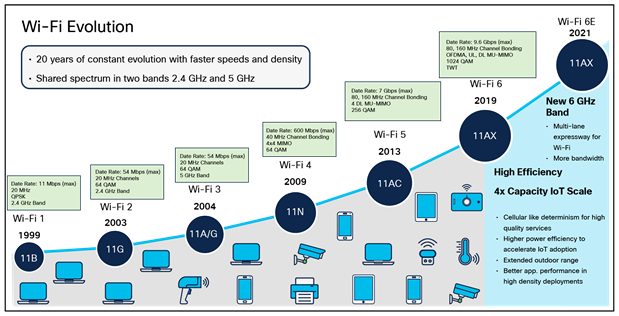
With each advancement of the IEEE 802.11 specification, letters were appended to the name, and after eight or so generations of 802.11 with revisions such as 802.11a, b, g, n, ac, ax, and now 802.11be, the Wi-Fi Alliance (a nonprofit organization), which owns the Wi-Fi trademark and is responsible for certifying interoperability among different manufacturers, created a more consumer-friendly approach similar to what is used in the cellular industry. Like the cellular approach of 3G, 4G, and 5G, the Wi-Fi Alliance now refers to these IEEE enhancements as Wi-Fi 0 through Wi-Fi 6E, with future generations being 7, 8, 9, etc. The figure below illustrates the evolution of Wi-Fi.
For an overview of the different IEEE standards, see “The Evolution of Wi-Fi Technology and Standards” at https://standards.ieee.org/beyond-standards/the-evolution-of-wi-fi-technology-and-standards/.
Interestingly, while the figure above shows 802.11a coming out in 2004, it actually came out at about the same time as .11b but was slower to be adopted.
Table 1. Wi-Fi generations (Source: https://en.wikipedia.org/wiki/IEEE_802.11)
| Generation |
IEEE Standard |
Adopted |
Maximum link rate (Mbit/s) |
Radio frequency (GHz) |
| Wi-Fi 7 |
802.11be |
(2024) |
1376-46120 |
2.4, 5, 6 |
| Wi-Fi 6E |
802.11ax |
2020 |
574-9608[3] |
6[a] |
| Wi-Fi 6 |
2019 |
|
2.4, 5 |
|
| Wi-Fi 5 |
802.11ac |
2014 |
433-6933 |
5[b] |
| Wi-Fi 4 |
802.11n |
2008 |
72-600 |
2.4, 5 |
| (Wi-Fi 3)* |
802.11g |
2003 |
6-54 |
2.4 |
| (Wi-Fi 2)* |
802.11a |
1999 |
|
5 |
| (Wi-Fi 1)* |
802.11b |
1999 |
1-11 |
2.4 |
| (Wi-Fi 0)* |
802.11 |
1997 |
1-2 |
2.4 |
| * Wi-Fi 0, 1, 2, and 3 are by retroactive inference. [4][5][6] |
||||
For an overview of the Wi-Fi Alliance, see the “Who We Are” page at https://www.wi-fi.org/who-we-are.
For an interesting perspective on the creation of Wi-Fi, see the following videos:
The History of Wi-Fi, Part 1: https://www.youtube.com/watch?v=1cStzl8AOf0
The History of Wi-Fi, Part 2: https://www.youtube.com/watch?v=8Mpq_A4RPzE
Overview of RF frequency bands
In the United States and many other places worldwide, three central frequency allocations (radio bands) permit the operation of Wi-Fi devices. These bands are referred to as the 2.4-, 5-, and 6-GHz bands. Access points, depending on the model, will support a minimum of 2.4 GHz, with most models supporting both 2.4 and 5 GHz. Some newer, more powerful access points, like the Cisco Catalyst™ 9162, 9164, and 9166 Series, support 2.4 and 5 GHz as well as the recently allocated 6-GHz band, sometimes called 6E. More on this later.
For an overview of Cisco Catalyst wireless products, see the following URL: https://www.cisco.com/c/en/us/products/wireless/product-listing.html
For an overview of Cisco Meraki products, see the Meraki product catalog at https://meraki.cisco.com/product-catalog/wi-fi/.
Wi-Fi radio bands and the frequencies used
Step 1. The 2.4-GHz band: 2.400 to 2.472 GHz
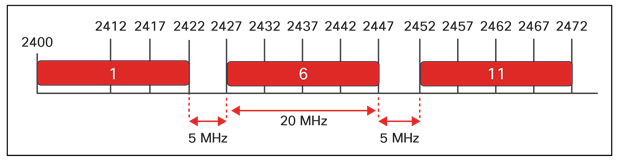
The 2.4-GHz band consists of frequencies between 2400 MHz and 2483 MHz, for 83 MHz of usable spectrum in most of the world. These channels are 20 MHz wide, and while it is possible to channel bond (combine two or more channels for higher throughput), this is not recommended or typically supported in enterprise-class networks because of the limited spectrum (channels supported).
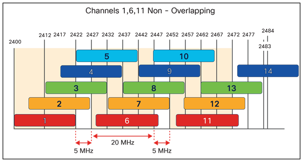
Channel frequency plans for the 2.4-GHz band identify 14 channels, but only 3 of these are nonoverlapping channels, 1, 6, and 11, highlighted in the figure; note that all other channels overlap or share boundaries and, in the U.S., only 1, 6, and 11 are available for noninterfering channel operation.
In some regulatory domains, it has been suggested that a 4-channel plan will work. However, this continues to come up repeatedly without going into much detail about what happens outside of the channel boundaries. There needs to be more space left between channels for this scheme to work practically in anything but the least dense environments. Also, consider that most of the world agrees on 1, 6, and 11, and most radios will default to this channel plan; in such a case, if you have selected 1, 5, 9, and 13, any radio using the standard channels will interfere with at least one—and in most cases two—of your channels. We do not recommend it for these reasons.
Many other non-Wi-Fi technologies also use the 2.4-GHz band for operation: microwave ovens, baby monitors, gaming consoles, Bluetooth devices, and cordless phones, to name just a few.
These other non-Wi-Fi devices represent interference to Wi-Fi signals, as they can interfere with Wi-Fi operations in the 2.4-GHz band. Does this mean that you won't be able to deploy Wi-Fi at 2.4 GHz successfully? No. It simply means that the 2.4-GHz band will fill up faster and support fewer users than the 5- and 6-GHz bands will. Often, enterprise deployments reserve 2.4 GHz for best effort or perhaps “guest access,” with the bulk of service being provided on 5 GHz and soon 6 GHz.
Tip: Valid strategies for reducing the congestion in 2.4 GHz include reducing self-interference by:
● Disabling the 802.11b (Wi-Fi 1) data rates to reduce the area of coverage/interference and eliminate the least efficient protocols, so you’re not cluttering the airwaves with slow throughput.
● Choosing a relatively high minimum mandatory data rate to reduce effective coverage and interference, as data rates of 12 to 18 Mbps are used in high-density deployments
The 5-GHz band: 5.150 to 5.925 GHz
While the 5-GHz channels don’t overlap, it is interesting to note that they do butt up against each other, unlike channels 1, 6, and 11, which have 5 MHz of separation, meaning that you can have adjacent channel interference. So in practice, you would want some spatial separation between 5-GHz access points on adjacent channels.
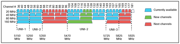
The 802.11 standard defines twenty-three 20-MHz-wide channels in the 5-GHz spectrum. Each channel is spaced 20 MHz apart and separated into three Unlicensed National Information Infrastructure (UNII) bands. Wireless devices specified as 802.11a/n/ac/ax can operate within these bands.
In the U.S., 5-GHz spectrum usage is defined with permitted channels being:
● UNII-1 (5.150 to 5.250 GHz) containing channels 36, 40, 44, and 48
● UNII-3 (5.725-5.825) containing channels 149, 153, 157, and 161
UNII-2 (5.250 to 5.350 GHz and 5.470 to 5.725 GHz), which contains channels 52, 56, 60, 64, 100, 104, 108, 112, 116, 120, 124, 128, 132, 136, and 140, is permitted in the U.S. but is shared with radar systems.
Therefore, access points operating on UNII-2 channels must use Dynamic Frequency Selection (DFS) to avoid interfering with radar signals. If an access point detects a radar signal, it must immediately stop using that channel and randomly pick a new channel. In the U.S., even without using the UNII-2 band, 5 GHz is well suited for high-density deployments because of its significant number of nonoverlapping channels.
Due to the limited spectrum, 40-MHz channels are used most often because 40 MHz is the “sweet spot” for high-density deployments to support a 7-channel plan.
The 6-GHz band: 5.925 to 7.125 GHz
Wi-Fi at 6 GHz is referred to by the Wi-Fi Alliance as Wi-Fi 6E and takes the IEEE 802.11ax protocol to the next level by introducing a brand new spectrum, 6 GHz. This new spectrum band is much broader than the legacy bands (2.4 GHz and 5 GHz), allowing wireless devices to take advantage of the performance enhancements introduced with Wi-Fi 6. The new spectrum is reserved for greenfield (a term that means fresh or new), meaning only Wi-Fi 6E (802.11ax) clients are supported in this band. In other words, no previous generations of Wi-Fi will be permitted to operate there.
Using 6 GHz eliminates the performance-robbing requirements of backward compatibility often experienced in previous spectrums. In addition, the amount of spectrum provided encourages and enables wider 80- and 160-MHz channels, dramatically increasing the speed while giving enough room to operate without the co-channel interference issues experienced in the 2.4- and 5-GHz spectrums.
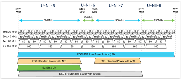
With the introduction of Wi-Fi 6E, the spectrum has been significantly expanded compared with 5 GHz and especially 2.4 GHz. From 5925 MHz to 7125 MHz, we now have fifty-nine 20-MHz channels, twenty-nine 40-MHz channels, fourteen 80-MHz channels, and seven 160-MHz channels.
For a deeper dive into 6-GHz spectrum regulations and deployment options, see the following URLs:
Some of this material is covered in this paper.
6-GHz Unlicensed Spectrum Regulations and Deployment Options white paper: https://www.cisco.com/c/en/us/products/collateral/wireless/catalyst-9100ax-access-points/ghz-unlicensed-spectrum-reg-wp.html.
The State of 6 GHz (video): https://www.youtube.com/watch?v=Ny0t-WiLk70
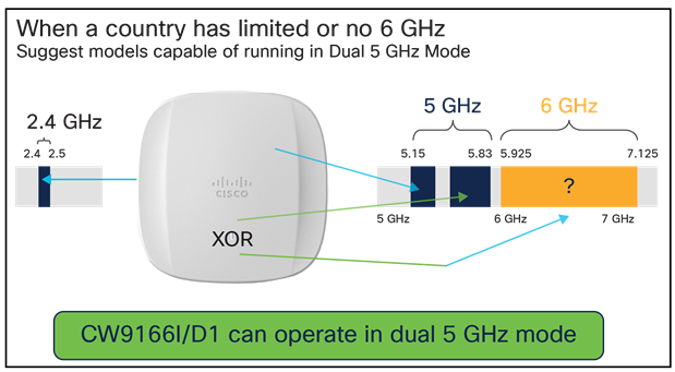
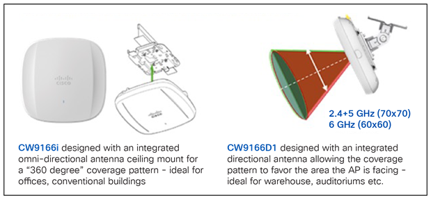
Tip: If you are not ready to deploy 6 GHz, or it is not currently permitted in your area, there are access points, such as the Cisco Catalyst 9166I (conventional omnidirectional) and 9166D1 with its integrated directional antenna, that will allow for XOR dual 5-GHz operation, and then the additional 5-GHz radio can be changed to 6 GHz when you are ready to support it.
Tip: If you are in a country that does not permit the full 6-GHz spectrum and perhaps supports only the lower 500 MHz, then as in 5 GHz, the use of 40-MHz channels is the channel plan that scales best.
● Unlike a telephone, Wi-Fi is half-duplex (listens and then sends). Slower protocols like Wi-Fi 0 take more time “on the air,” slowing networks down overall (we recommend turning off slower 802.11b data rates).
● 2.4 GHz is limited in bandwidth and has only three nonoverlapping channels.
● 5 GHz is ideal for faster Wi-Fi 4 and above networks (it is the most popular today).
● 6 GHz has new spectrum (more than 2.4 and 5 GHz), but only Wi-Fi 6E or later devices can use the spectrum.
● The higher the frequency, the shorter the radio wave (this typically means more energy to go the same distance). That is why 2.4 GHz travels farther than 5 GHz (5 and 6 GHz are similar).
● The strength of a transmitted signal is measured in decibel-milliwatts (dBm). +3 dBm is a noticeable improvement of a client signal, and +6 dBm often doubles the range.
● Antenna gain determines how the power is radiated. Lower-gain antennas are usually omnidirectional, much like a light bulb with no lampshade (360 degrees). Higher-gain antennas do not give you more power; they focus the power in a given direction. High gain omnidirectional flattens that signal like a pancake, and directional focuses the energy in a given direction.
● In addition, the farther the signal travels, the weaker it gets. 2.4 GHz goes farther because the radio wave is more significant (it is a physically bigger radio wave), so it takes less power to travel the same distance than 5 or 6 GHz would.
● Access points should be in close proximity to the users. Much like a reading light, an access point will work best if it is in the near field, so the signal doesn’t have to travel as far.
● Wi-Fi can transmit through objects, but as it does, the signal gets significantly weaker, referred to as attenuation (measured in dB). Sometimes higher-gain antennas can help with this.
● As Wi-Fi signals travel through objects, signal loss (attenuation) occurs. Some objects have more loss than others. Typical objects are brick walls (10 dB attenuation); concrete, which has more metal (12 dB); and drywall (typically 3 dB). The amount of attenuation depends on metal, moisture, thickness, and conductivity.
● Each access point creates a wireless cell. Cells should slightly overlap and, if possible, not be on the same channel. In the case of 2.4 GHz, you have only channels 1,6, and 11. Other bands have plenty of nonoverlapping channels to develop a proper channel plan.
● When measured at the receiver, signal strength is expressed as a negative dBm number. -66 dBm is often used as a standard value to survey for client cell coverage. Note: At one time, -67 was used. However, for newer Cisco IOS® devices and newer Wi-Fi phones, -66 dBm is a better number.
● Radio waves often reflect off objects; this is called multipath. Typically, if a signal bounces, it arrives at the access point or client antenna perhaps two or more times. These signals can add to, subtract from, or distort the signal. This is very bad when using Wi-Fi 0 through 3; Wi-Fi 4 and above uses multiple antennas and Orthogonal Frequency-Division Multiplexing (OFDM) modulation to overcome some of the more problematic issues with multipath.
● Channel bonding is when more than one channel is used for additional throughput.
● In 5 GHz (under U.S. Federal Communications Commission [FCC] rules), when you bond, a channel signal goes down 3 dB because the same power is spread over two channels. In 6 GHz (low power), the power increases when you bond a channel. This is why the range 5 GHz at 20 MHz is like 6 GHz at 40 MHz. Note that the opposite holds true in other countries, such as the UK.
● The amount of information transmitted over the air is a factor of bandwidth, number of streams, data rate, length of time on the air, and, of course, the type of complex modulation used.
● A site survey is the act of physically testing the coverage area of the WLAN cell.
● WLAN cells can be modeled in software using third-party tools like Ekahau, Hamina, IB Wave, etc.
● 6-GHz products (in the U.S.) can use the entire band (if low power), but other areas worldwide can be limited to 500 MHz. Also in the U.S., if standard power is used, it must be frequency coordinated, and there are limitations on the frequencies, which we will address in this guide.
● In the upcoming Wi-Fi 7, you will hear the term Multi-Link Operation or MLO, a method by which one client can communicate with an access point using multiple radios concurrently for a faster and more robust connection.
● In Wi-Fi 4 and above, the access points have multiple radios/antennas on each band. 4x4 or 3x3 refers to the number of radios in that band. If you see something like 4x4:3, it has four radios in the band capable of three spatial streams.
● Three or four spatial streams mean the radios can send different information on each radio in a “stream,” so in 4x4:3, the access point would have four radios but only three other signals. In this case, the fourth radio augments the three signals.
Tip: Confusion can arise when discussing the number of radios versus the number of spatial streams. Technically, when discussing the number of radios in each access point, the radio is often designated as a “slot” in software. For example, the Catalyst 9120 has one 2.4-GHz radio (slot 0) and one 5-GHz radio (slot 1); therefore, it has two serving radios. A radio that supports multiple spatial streams is still a single “radio” in a sense, but one that supports multiple transmit (Tx) and receive (Rx) chains. Thus, a 3x4:3 radio is one radio with three Tx chains and four Rx chains supporting a total of three spatial streams. The confusion is that it can be considered as multiple radios (because a given radio that supports multiple Tx and Rx chains is, in a sense, a radio with multiple internal radios to support these chains). Therefore, each Tx/Rx chain is technically a radio, but the software defines it as a single “radio slot.”
6-GHz deployment considerations
The actual frequency (6 GHz) isn’t much different than 5 GHz, but there is a big difference in the methods by which RF transmit power is assigned and when external antennas and outdoor deployments are permitted.
Most access points today operate in what is known as low power in the 6-GHz band. This works well in access points used for indoor deployments and can use frequencies across the entire band without any limitation on the spectrum or requiring Automatic Frequency Coordination (AFC), discussed in more detail later.
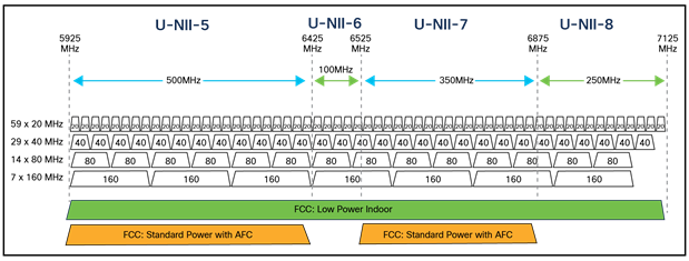
One key advantage of a low-power operation is the ability to use the entire 1.2-GHz bandwidth in the UNII-5 to UNII-8 range. This allows wider channels, with up to seven 160-MHz channels in nonoverlapping operation. Why would 160 MHz even be considered for a multiclient deployment? First, the output power, defined as dBm per MHz (dBm/MHz), allows the link to keep the same system gain no matter what bandwidth is used. This is not the case in the 5-GHz spectrum. Second, all clients in 6 GHz will support Orthogonal Frequency-Division Multiple Access (OFDMA). OFDMA uses a “resource allocation” concept that effectively subdivides the channel. Therefore, small packets can be aggregated into the broader spectrum efficiently. In addition, the low-power operation has no AFC requirements, simplifying its deployment model.
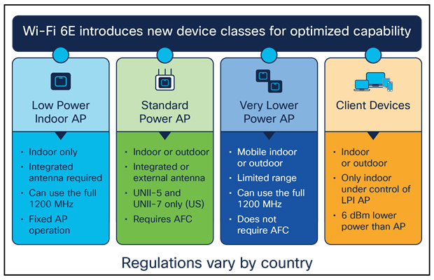
Requirements for low-power use
● Must be indoors (the access point cannot be “weatherized”).
● Must have a permanently attached antenna.
● May not be battery powered.
● Must employ a contention-based protocol.
● Maximum Equivalent Isotropic Radiated Power (EIRP) is 5 dBm/MHz.
● Client maximum power is 6 dB below the access point’s maximum power, like the requirement in standard power.
● As in standard power, mesh/extender devices can operate with the same conditions as the access point.
● Must be clearly labeled with a notice that states that “FCC regulations restrict operation of this device to indoor use only.”
The defining condition of the low-power mode is a constant Power Spectral Density (PSD) of 5 dBm/MHz. The maximum power level for a chosen bandwidth can then be calculated as 5(dBm/MHz) + 10log(B(MHz)). This means that the allowed EIRP will range from 18 to 27 dBm based on bandwidth (20 MHz to 160 MHz). When using the higher bandwidth, the allowed transmitted power is very similar to the maximum transmitted power in the 5-GHz spectrum.
Takeaway: A 6-GHz access point radio can provide coverage similar to a 5-GHz cell while dramatically increasing capacity, allowing for a one-to-one replacement of a 5-GHz cell, assuming an average access point density of 1200 to 2000 square feet in a carpeted office with a standard ceiling height (3 meters or approximately 10 feet). Standard access point deployment densities typically vary from 1000 to 1500 square feet. A density of 1000 square feet = 1 access point every 36 feet (11 meters), 1200 square feet = 1 access point every 40 feet (12 meters), and 1500 square feet = 1 access point every 44 feet (13.5 meters). Ideally, access points should be on different nonoverlapping channels and should not hear one another on the same channel above -82 dBm. Cisco Radio Resource Management (RRM) is typically used to automate this method, dynamically assigning channels and bandwidths.
Cisco and Meraki access points that operate in low-power mode
● Cisco Catalyst 9136 Series
● Cisco Meraki MR57
● Cisco Catalyst 9162I, 9164I, and 9166I can operate in either Meraki or EN mode
The products above have integrated omnidirectional antenna systems. For customers who typically use external directional antennas (given that they are prohibited in low-power mode), Cisco has introduced the Cisco Catalyst 9166D1 (based on the 9166 access point design but with an integrated 6-dBi directional antenna array. This not only satisfies most indoor directional antenna use cases but also satisfies the requirements for low power. This model works on both Meraki and EN platforms. All the access points listed previously can also operate at standard power. We will define this below.
Standard power can operate only in a subset of the 6-GHz band (the UNII-5 and UNII-7 bands). Standard power works most like the FCC rules for the 5-GHz spectrum. EIRP is the amount of power transmitted by the antenna of a device. The maximum EIRP possible is 36 dBm for either band (6 GHz adds a full PSD of 23 dBm/MHz, which limits power for narrower-band applications). However, to use these higher power levels in the 6-GHz band (UNII-5 and UNII-7), there must be governance to protect incumbents (licensed band users). It should also be mentioned that standard power is optimized for 20-MHz (not bonding) operation, which is a bit different from low power, which is optimized for 80 MHz (4-channel scenario).
The FCC has set up a framework whereby commercial entities can offer this governance as a service that will dictate how much EIRP an unlicensed device can transmit on any given channel or whether the device will be allowed to transmit at all. This service is called Automatic Frequency Coordination (AFC). Efforts are ongoing to define the interaction between the AFC systems and between AFC systems and devices. The current attempt revolves around developing the test cases for these systems, which was planned to conclude near the end of 2022. At the time of this paper (February 2024), FCC approval of AFC is expected to occur very soon, with approvals in other countries expected to follow.
AFC (and the aspects below) should be utterly transparent to the customer, with customer interaction limited to GPS placement and enabling AFC in software, but here is an overview of how it works.
Unlike AFC for the Citizen Broadband Radio Service (CBRS) spectrum, AFC for 6 GHz will not provide any policing between newly deployed devices. It will police only interference between new devices being added and incumbent devices.
To do this, the location of the new device must be determined with 95% confidence of reported accuracy. For example, if the accuracy reported is +/- 1 cm, the confidence that the device is within that boundary would likely be low. If, however, the accuracy reported is +/- 1 km, the confidence that the actual location is within this boundary would be very high. This 95% accuracy boundary then becomes the location from which calculations are performed to determine whether interference exists.
The calculations to determine what power level to use are based on two primary factors. First, industry-standard propagation models, along with margin (such as indoor/outdoor loss or fade margins), are used to compute the potential signal seen at the incumbent’s site. Second, the signal level at the incumbent’s receiver must be at least 6 dB lower than the noise floor. This is a typical calculation used for RF measurements, in that adding a signal that is 6 dB below a given signal will increase the total signal power by 1 dB and consequently create a 1-dB loss of sensitivity to the incumbent (both in-band and adjacent channel interference are considered). Different propagation models are used depending on how far away the new device is from the incumbent, such as near field, clutter-based, and over-the-horizon models).
Standard-power devices can be deployed indoors or outdoors, and the antenna height must be reported along with the location and the previously mentioned accuracy level. Height above ground can be either automatically or manually determined. Given the height, uncertainty boundaries, and appropriate propagation model, a maximum EIRP the device can transmit can be defined. The device can operate at a given frequency if it meets the “6 dB below the noise floor” requirement in the incumbent’s system.
Devices must demonstrate that they will operate at or below the power limit provided by the AFC system. In addition, devices must contact the AFC system at least every 24 hours to ensure that any changes to the incumbent’s occupancy are reflected in the power levels of the devices, or they must cease operation (up to 11:59 p.m. the day following the missed 24-hour window).
Deployments can meet the required AFC condition in different ways. A single outdoor access point with an internal location device (GPS in most cases) will report that device’s location, height, and accuracy. This is a straightforward implementation example. Indoor locations, however, often cannot place a GPS at every access point or device. In this case, a proxy can be used. This proxy performs two primary functions. First, it guarantees that the power level allowed by the access point is what the AFC requires. Second, it provides a location based on where the GPS antenna is relative to the locations of the access points. The access points’ locations close to the GPS location will then be reported as “inaccuracies” and added to the accuracy boundary to ensure a 95% confidence level that all access points are located within this boundary.
It is therefore essential to consider where the antenna will be located relative to the farthest access point. Placing the antenna at the corner of a rectangular building would result in greater inaccuracy than putting it in the center of the building.
The AFC system must provide a power control resolution of 3-dB increments or less and a range of 21 to 36 dBm to the devices under the control of the AFC system. In addition, the AFC must reflect the addition of incumbent sites within 24 hours of the incumbent reporting the additional site.
In addition to AFC requirements, several other requirements apply to a standard-power deployment, as described below.
Additional requirements for standard-power use
● EIRP 30 degrees above the horizon must be below 21 dBm.
● Probing is not allowed (this is an effort to reduce neighbor messages).
● Hotspots are not allowed.
● Vehicular deployments (even battery-powered devices) are not allowed (except for commercial aircraft above 10,000 feet).
● All devices (or the proxy) must report their serial number and FCC ID.
● Permanently fixed client devices can be registered with AFC and transmit the same power level (under the same restrictions) as a reporting access point (these include devices such as workgroup bridges or mesh access points that are permanently fixed).
Client devices for both standard power and low power have similar requirements. They can transmit only up to 6 dB below the maximum transmit power “allowed” for the access point. If the access point is transmitting at 6 dB below its allowed maximum (such as for radio resource management reasons), the access point and the client could transmit at the same power. The purpose of this requirement is to limit the maximum distance a client can be from an access point, but keep in mind that most access points have at least four antennas for the receive function, which will provide a 6-dB (10log(4)) increase in receive gain (effective sensitivity) to balance the link.
On November 2, 2022, the FCC released a public notification announcing “conditional approval” for AFC systems. While this does not mean the AFC system is ready for operation, it provides the green light for public trials for each of the 13 AFC applicants to demonstrate compliance with the FCC commission rules.
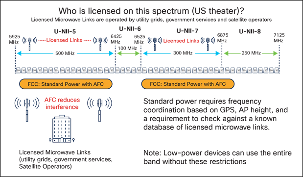
Table 2. Expanded unlicensed use of the 6-GHz band (Source: FCC DA 22-1146)
| Device Class |
Operating Bands |
Maximum EIRP |
Maximum EIRP Power Spectral Density |
| Standard-Power Access Point (AFC Controlled) |
U-NII-5 (5.925-6.425 GHz) U-NII-7 (6.525-6.875 GHz) |
36 dBm |
23 dBm/MHz |
| Fixed Client (AFC Controlled) |
36 dBm |
23 dBm/MHz |
|
| Client Connected to Standard- Power Access Point |
30 dBm |
17 dBm/MHz |
|
| Low-Power Access Point (indoor only) |
U-NII-5 (5.925-6.425 GHz) U-NII-6 (6.425-6.525 GHz) U-NII-7 (6.525-6.875 GHz) U-NII-8 (6.875-7.125 GHz) |
30 dBm |
5 dBm/MHz |
| Client Connected to Low-Power Access Point |
24 dBm |
-1 dBm/MHz |
Cisco and Meraki standard-power update as of February 2024
At the time of this writing, Cisco is in a beta program, with customers testing access points with the FCC’s AFC for customer release. The FCC is expected to approve AFC for Wi-Fi use at any time, with other countries expected to adopt similar functionality.
All the access points listed earlier for low-power mode can also operate in standard-power mode, provided these conditions are met:
● Some of the access points will need to have a GPS module installed (CW-ACC-GPS1=).
● Access points with GPS modules will need to be located where a suitable GPS (GNSS) lock can be acquired. If the access point is indoors, this usually means it should be located near a window. If this is not possible and it cannot get a GPS lock, the module does support an external antenna so that the antenna can be located near the window or outdoors.
● The network will need to always connect to the internet to coordinate with the AFC server, as there is a requirement to coordinate with the AFC at least once every 24 hours.
● Meraki and/or EN software needs to be configured for standard power and AFC.
The access point GPS module is an option because it is unnecessary when the access point operates in low-power mode. In standard-power mode, only a few access points are likely to be in areas capable of receiving a GPS/GNSS signal. It is recommended that units near windows with a sky view have GPS/GNSS functionality, assuming standard power is desirable.
The GPS/GNSS module uses the USB port. The power draw is minimal and will not impact Power over Ethernet (PoE) requirements. Wi-Fi 6E access points for outdoor use will have integrated GPS/GNSS, but it made more sense (in terms of sustainability, environmental, cost, etc.) not to embed it into every access point product.
Cisco and Meraki access points that operate in standard-power mode
● Cisco Catalyst 9136 Series
● Meraki MR57
● Cisco Catalyst 9162I, 9164I, and 9166I can operate in either Meraki or EN mode
In addition to the above access points, as new products for outdoor use are released, they can be found at the following URLs:
Additional thoughts on Wi-Fi 6E
Regardless of your choice to deploy in low-power or standard-power modes, both Wi-Fi 6E and Wi-Fi 6 are based on the throughput and performance enhancements gained in IEEE 802.11ax.
Some of these enhancements include:
● Higher capacity (better user experience even with high utilization)
● Improved power efficiency (improving battery life of portable devices)
● Reduced latency (optimizing packet scheduling and improving radio airtime efficiency)
● Increased speed, four times faster than previous versions of Wi-Fi
● Improved security: Wi-Fi Protected Access (WPA3) is available in Wi-Fi 6 and mandatory in Wi-Fi 6E
The OFDMA enhancements allow for more regular and consistent packet delivery over OFDM, and users don’t have to wait as long.
Here’s another way to put it. With OFDM, any time a user requests a data packet, it would essentially send out one truck to meet each user’s request, which isn’t very efficient. OFDMA is different; one truck delivers the packet to individual users in one round. This way is far more efficient and takes less time. The figure below illustrates the difference between OFDM and OFDMA.
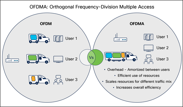
All previous versions of Wi-Fi enhancement (as well as Wi-Fi 6 and 6E) centered around channel bonding, spatial streams, more complex modulation, and other features that improve throughput. OFDMA is all about reducing latency by using the time on the airwaves as efficiently as possible, which is one of the main reasons you want your network to be Wi-Fi 6 and 6E capable.
All the improvements in Wi-Fi 6 (used in 5 GHz) are replicated in Wi-Fi 6E (6 GHz), but the main advantage of 6 GHz is that it is new and has been designed from the ground up with these key features:
● Many more channels: 59 at 20 MHz, 29 at 40 MHz,14 at 80 MHz, and 7 at 160 MHz.
● Channel bonding scales better due to the much greater number of channels (spectrum available).
● Entry into 6E requires the latest and best clients (no slow legacy devices).
● Requires the most efficient clients with the latest security (WPA3).
● Low-power 6E is easy to deploy; cell sizes can scale with 5-GHz cells.
● Standard-power 6E allows for outdoor and external antenna deployments requiring a longer range.
Understanding Wi-Fi 6E clients
The Wi-Fi 6E specification was proposed by FCC Chairman Pai on April 1, 2020, after winding through the IEEE for ratification, emerging as 802.11ax. The Wi-Fi Alliance, in January 2021, began its Wi-Fi 6E certification program. As of this writing, almost two years have passed since enterprise-class 6E access points have been available. A significant number of 6E clients are on the market today, including the latest products from companies like Apple, Intel, and Samsung. Wi-Fi 6E is being integrated into tablets, phones, notebooks, and application-specific devices at a breakneck pace; newer WLAN deployments should certainly consider supporting 6E in the future.

Tip: Only Microsoft Windows 11 or later supports 6E. Regardless of the operating system, review the client drivers and operating system used to determine suitability when possible.
Tip: You should consider enabling WPA3 on 2.4 and 5 GHz to support roaming of 6-GHz clients. You will also want to review the WPA3 Deployment Guide at: https://www.cisco.com/c/en/us/products/collateral/wireless/catalyst-9100ax-access-points/wpa3-dep-guide-og.html
Tip: Avoid using “hidden” SSIDs, as they can cause issues with 6-GHz probe behavior. This behavior is not specific to Cisco but is how the standard is defined and how clients behave. Older non-6-GHz clients can send probes, so hidden SSIDs can work for them, but 6-GHz clients do not send probes, making hidden SSIDs are problematic.
A few popular 6E clients and versions tested:
| Client Vendor |
6E Clients |
Version Tested |
6E Preference |
| Apple |
iPad Pro, Macbook Pro M2 |
iPad OS 16.4, MacOS: 13.5.2 |
Prefers 6G |
| iPhone 15 Pro (under testing) |
iOS 17 |
||
| Samsung |
S21 Ultra, Galaxy Z Fold, S22+, S23 |
Android 13 |
Prefers 6G |
| Intel |
AX210, AX211, AX411 |
22.250.1 |
Prefers 6G |
| Google-Pixel |
Pixel 6, 6 Pro, 7 and 8 |
Android 13 |
Prefers 6G |
| Google Chrome OS |
ChromeOS with Intel AX211 |
116.0.5845.120 |
Prefers 6G |
| ChromeOS with Mediatek MT7922 |
116.0.5845.120 |
||
| ChromeOS with QCA WCN6856 |
116.0.5845.120 |
||
| Zebra |
TC22, TC53, TC58, TC73, TC78 |
Android 13 |
Prefers 6G |
Cisco has relationships with most of the 6E client manufacturers; Cisco engineering tests interoperability with Wi-Fi 6 and 6E clients on our WLAN networks. The table above is a snapshot (as of this writing) listing some of the popular 6E clients and the versions we have tested. In addition to those clients, other clients such as Broadcom, Qualcomm, NXP, Xiaomi, Asus, and Redmagic also work with a preference of 6E.
Tip: The client list in the table above is only a snapshot and will likely become outdated as newer products enter the market. The testing was done to verify our interoperability internally and is shared as a courtesy.
Consult the Wi-Fi Alliance for an updated list to determine interoperability between different Wi-Fi 6 and 6E clients. To determine if the Wi-Fi Alliance has tested a 6E client for interoperability, see the Certification page at https://www.wi-fi.org/certification.
Antennas: Solving multipath distortion (Wi-Fi 4 through 6E)
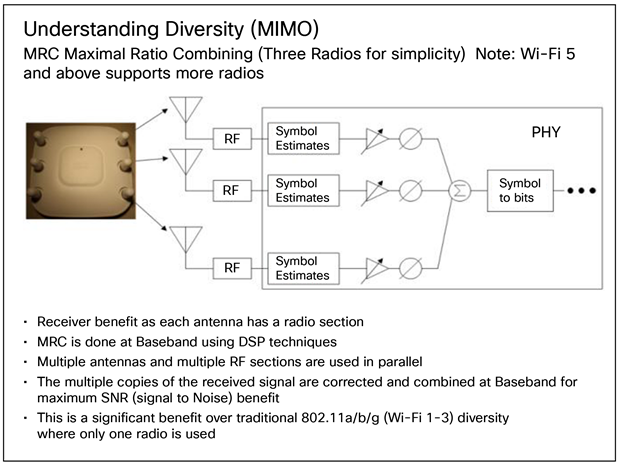
Before Wi-Fi 4, it was one radio (sharing two antennas in a switching fashion) working as a Single-Input Single-Output (SISO) device; however, the advent of IEEE 802.11n (Wi-Fi 4) introduced Multiple-Input Multiple-Output (MIMO).
This is an entirely new concept; instead of a single radio, multiple radios (each with its own antenna) are now used to increase the data rates. Additionally, a weak signal or a signal with multipath distortion is now heard by more than one radio, and MIMO can be used to reconstruct the data with frame aggregation. This approach to solving multipath distortion means that, instead of one radio switching antenna, you typically have four radios, each with a discrete antenna, hearing the signal simultaneously and “putting it back together.”
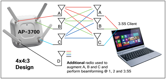
The notation 4x4:3 indicates the antenna’s behavior on a given band (2.4 or 5 GHz). However, these antennas are “dual band” (orange stripe), so it is a dual-band access point. This means that there are eight radios (four radios in each band) and all eight radios are sharing the four antennas. This dual-band antenna design is also called a Dual Radiating Element (DRE), as the antenna is resonant (tuned to operate on both 2.4 and 5 GHz). This was done to reduce the number of antennas present on the access point. As you can see in the figure below, using a better signal processing method called Maximal Ratio Combining (MRC) allows data from all three antennas to be combined for best decoding.
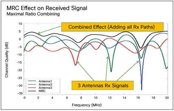
MRC results in a better-decoded signal with a much better signal-to-noise ratio (SNR). (This is only one of the many improvements found in later versions of Wi-Fi. Because this section focuses on the antenna technology, it does not attempt to cover all the improvements within the different versions of Wi-Fi.) In addition to combining antennas, antennas can be used in other fashions, such as sending additional data to different clients or the same client. This is known as a “spatial stream,” and the nomenclature goes like this:
4x4:4 indicates 4 transmitters, 4 receivers, and 4 spatial streams; 2x2:2 indicates 2 Tx, 2 Rx, and 2 spatial streams, etc.
Brief overview of MIMO, multipath, and MU-MIMO
MIMO has been around for a long time. It was first introduced in the Cisco Aironet® 3500 Series, and one of the significant advancements in Wi-Fi 4 and above is the parallel processing of RF signals.
In addition to spatial streams, another improvement called transmit beamforming (TxBF) in later versions of Wi-Fi allows the access point to focus the signal using multipath benefits, also referred to as constructive/destructive interference, along with more complex modulation schemes (OFDM, etc.) to take advantage of multipath.
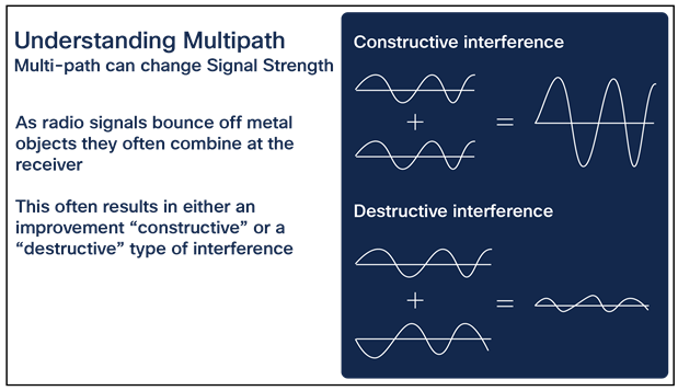
Takeaway: As signals bounce and arrive at the receiving end, they can combine and get stronger. Inversely, if the goal is to send different data to different clients (say, one spatial stream to one client while sending an additional spatial stream with other data to yet another client concurrently), all these antennas can use “destructive” interference as a tool (provided the clients are spatially apart, meaning not next to each other). This essentially allows different signals to reach additional clients without interfering with the individual client streams. Of course, the purpose of all this is to get more data “out in the air” more quickly, as the faster the access point can send the data, the faster it can service other clients, with the benefit being more data, lower latency, and fewer retries, for a better user experience.
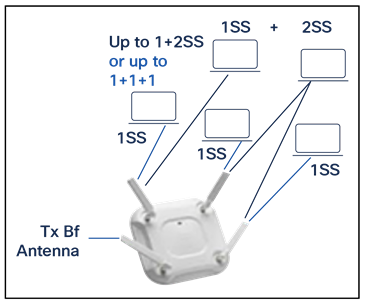
Referred to as multiple-user MIMO (MU-MIMO), in this case the extra transmit beamforming antenna reinforces the different signals (taking advantage of constructive and destructive interference). Note: This assumes that the clients are not right next to each other; there must be spatial distance between clients to make this work.
Understanding external and internal antennas beyond Wi-Fi 3
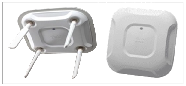
Now would be a good time to start understanding access point antennas. Wi-Fi 1 through 3, as previously stated, tended to have a maximum of four antennas (two on 2.4 GHz and two on 5 GHz). With more radios (typically eight radios), it quickly became untenable to have eight antennas “sprouting” from the access point.
For aesthetic purposes, a push was made for integrated antennas (hiding the antennas from view), and the external antenna models were designed to rely on a “shared” DRE (dual-band) approach, so the eight radios onboard the access point could share the four antennas in both 2.4- and 5-GHz mode.
The internal antenna designs could be Single Radiating Element (SRE) or DRE, with the design intended to allow the access point to be ceiling mounted and have the antennas radiate downward in a 360-degree fashion; this is referred to as “omnidirectional,” which is basically how the external dipole antennas were designed to radiate.
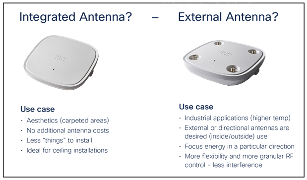
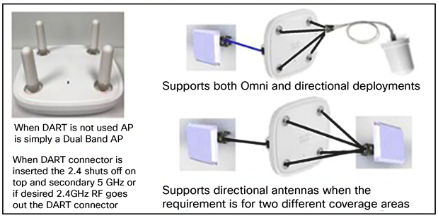
In addition to the Wi-Fi antennas that service clients growing to eight in number, additional technology features, such as radios for Bluetooth and security monitoring/spectrum analysis, required additional antennas. Another feature referred to as XOR permits some access point models to switch from 2.4 and 5 GHz to a mode in which 2.4 GHz is disabled and converted into an additional 5 GHz for coverage. Products like the Cisco Catalyst 9166 Series can be converted from 5 and 6 GHz to one supporting dual 5 GHz.
Some access point models, especially those with internal antennas, required the dual 5 GHz to be broken down into a micro-macro cell configuration to get the needed RF isolation between bands. This is not an issue with external antenna models, as the antennas can operate at full power when spatially separated for better isolation and/or to cover two different cell areas. Use cases include covering two different aisles in a warehouse, covering two different classrooms in a school, or segmenting the RF into two different cells to cover two different areas of an auditorium or a large venue. Also, the two sets of external antennas can be configured to cover (approximately) the same cell area to provide greater capacity.
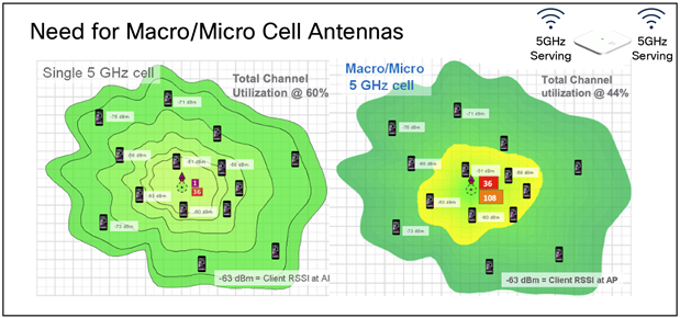
Starting with the Catalyst 9166 Series, Cisco is moving toward a macro-macro approach. While the macro-micro cell approach works, it is best suited for areas with a heavy concentration of stationary clients, for example, a call center, or an area with fixed users in, say, an executive conference room priority.
Tip: The micro-macro cell can be problematic once you have many actively moving clients running real-time media applications such as voice over Wi-Fi or Microsoft Teams. These “microcells” may be an attractive nuisance for such a client, yielding a choppy user experience. Why?
● A client near the access point may scan the microcell radio as a good candidate and then the user may briskly walk out of range of that radio. Then, when the client needs to roam, it may pick the microcell, only to suffer a failed roam and perhaps a multisecond audio/video gap as the client performs a panic scan.
● Understand that even a client optimally designed for active scanning may have entries in its scan list that are, at best, 5 seconds old. Within 5 seconds, a lot can happen—a user can move around a hallway corner, close a metal door, etc.
● For these reasons, macro-macro cells are preferred and can be accomplished using products with external antennas.
Antennas are designed to cover specific frequencies.
1. If the wrong antenna is used, the energy will not leave the antenna properly (poor performance).
2. Radio waves are a specific physical size (the higher the frequency, the smaller the radio wave).
3. If the antenna covers only one band, it is a Single Radiating Element (SRE).
4. If the antenna covers more than one band, it is a Dual Radiating Element (DRE), or a tri-band (TRE) if it also includes 6 GHz.
5. Antennas have gain measured in decibels relative to isotropic gain (dBi), measured against dipole in free space. The higher the gain, the better the range; gain helps transmit and receive.
6. Each access point model has an approved antenna list showing the type and maximum gains permitted.
7. Antennas can be omnidirectional (360-degree pattern) or directional, allowing the energy to be focused.
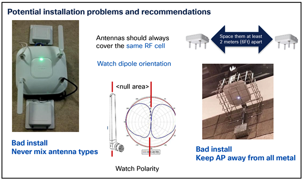
8. Access points with internal antennas should be at least 2 meters from any other access point or radio device.
9. Avoid placing access points or antennas near metal objects, as these objects will affect the antennas’ directional properties.
Antenna properties and ratings
An antenna gives the wireless system three fundamental properties: gain, direction, and polarization. Gain is a measure of an increase in power. Direction is the shape of the transmission pattern. A good analogy for an antenna is the reflector in a flashlight. The reflector concentrates and intensifies the light beam in a particular direction, as a parabolic dish antenna would do to a RF source in a radio system. Polarization is the orientation of the radio wave; typical polarities are vertical, horizontal, or circular.
Antenna gain is measured in decibels as a ratio between two values (dBi). The gain of a specific antenna is compared to the gain of an isotropic antenna. An isotropic antenna is a theoretical antenna with a uniform three-dimensional radiation pattern (like a light bulb with no reflector). dBi is used to compare the power level of a given antenna to the theoretical isotropic antenna. The U.S. FCC uses dBi in its calculations. An isotropic antenna is said to have a power rating of 0 dB, meaning that it has zero gain or loss compared to itself.
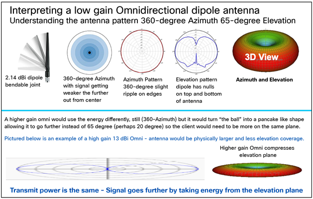
Unlike isotropic antennas, dipole antennas are real antennas. Dipole antennas have a different radiation pattern compared to isotropic antennas. The dipole radiation pattern is 360 degrees in the horizontal plane and 75 degrees in the vertical plane (assuming the dipole antenna is standing vertically) and resembles a doughnut in shape. Because the beam is slightly concentrated, dipole antennas have a gain over isotropic antennas of 2.14 dB in the horizontal plane. Thus, dipole antennas are said to have a gain of 2.14 dBi (in comparison to an isotropic antenna).
Some antennas are rated in comparison to dipole antennas. This is denoted by the suffix dBd. Dipole antennas have a gain of 0 dBd (2.14 dBi). It is interesting to note that most of the sales documentation refers to dipole antennas as having a gain of 2.2 dBi. The actual figure is 2.14 dBi, but it is often rounded up.
Cisco offers several different styles of antennas for use with access points and bridges in both 2.4-GHz and 5/6-GHz products. Every antenna offered for sale has been FCC-approved. Each type of antenna will offer different coverage capabilities. As the gain of an antenna increases, there is some tradeoff in its coverage area. Usually, high-gain antennas offer longer coverage distances, but only in a certain direction. The radiation patterns below will help to show the coverage areas of the styles of antennas that Cisco offers: omnidirectional, Yagi, and patch antennas.
An omnidirectional antenna is designed to cover a 360-degree radiation pattern. Most integrated antenna access points use this type of design unless expressly stated otherwise.
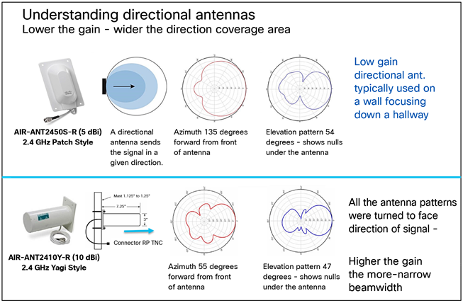
Directional antennas come in many different styles and shapes. An antenna does not offer any added power to the signal; it simply redirects the energy it receives from the transmitter. Redirecting this energy has the effect of providing more energy in one direction and less energy in all other directions. As the gain of a directional antenna increases, the radiation angle usually decreases, providing a greater coverage distance but with a reduced coverage angle. Directional antennas include patch antennas, Yagi antennas, and parabolic dishes. The higher the gain of an antenna (above 6 dBi), the more directional it is. In some cases, the installer must be very accurate in aiming these antennas to get the proper cell area covered.
In the case of point-to-point bridging or workgroup bridge applications, two directional antennas pointing at each other can be extremely difficult to aim (especially high-gain antennas like parabolic dishes). Installers will often align the first high-gain directional antenna to an omnidirectional one (because it is easier to link), then replace the omnidirectional antenna with another high-gain directional one, aligning it to the already focused directional. Some products have alignment software; other times, it is up to the installer to align using lasers, balloons, or other visual or hardware devices.
A directional antenna can often improve a weak signal because the gain works in both directions, Tx and Rx. Since the directional antenna receives signals only where it is pointing and is not “hearing in 360,” it often encounters less interference, resulting in a much higher SNR.
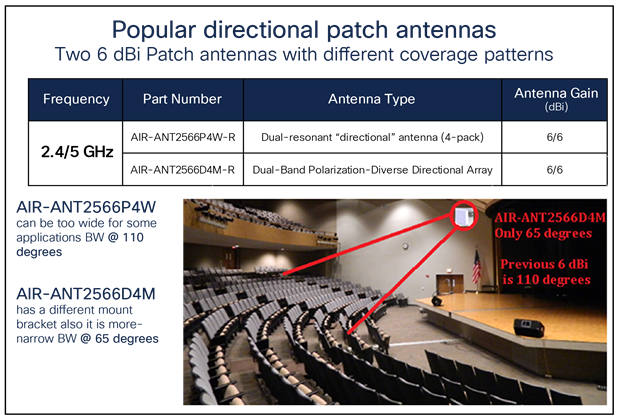
Some access points have a maximum of 6 dBi for regulatory reasons. When this happens, it is sometimes desirable to create more than one directional antenna with the same gain. In the use case shown in the figure above, a narrower beamwidth (65 degrees) was needed to best cover two different areas of the theater.
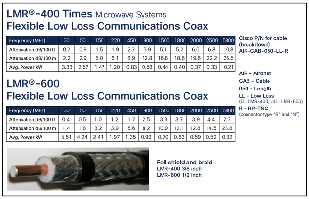
Cabling introduces losses into the system, negating some gains and reducing the range of the RF coverage. If a cable is outdoors, using lightning arrestors is a good practice.
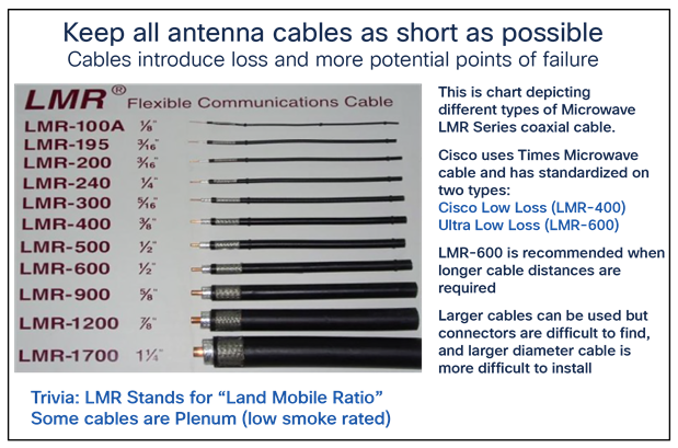
Tip: “Leaky coaxial cable,” where the cable is functioning as a long antenna, should not be used. While it was a viable option on older single-antenna systems, such as 802.11a and 802.11b, that used only one radio, leaky coaxial cable cannot support the multiple radio transmit and receive chains used by 802.11g and above.
According to the U.S. Federal Code of Regulations, products used in the 2.4- and 5-GHz industrial, scientific, and medical (ISM) bands manufactured after June 1994 must either use connectors that are unique and nonstandard (meaning not readily available on the market for the average user) or be designed to be professionally installed (“professional” here indicates a person trained in RF installation and regulations). Since many of the 2.4-GHz products are installed by non-RF-trained personnel, these products must comply with the unique connector ruling. The Cisco outdoor access and bridge products are designed for installation by an RF professional and therefore may use a standard N-type connector. Cisco Aironet indoor products use reverse polarity-TNC (RP-TNC) and sometimes N-type connectors (mostly outdoor products).
To ensure compatibility with Cisco Aironet products, use antennas and cabling from Cisco.
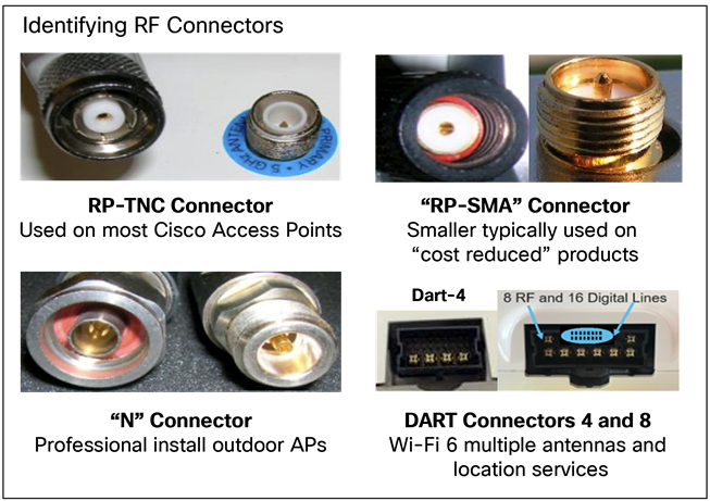
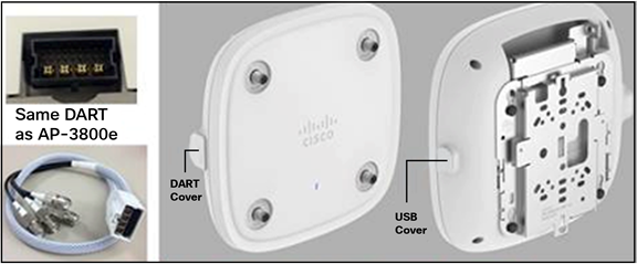
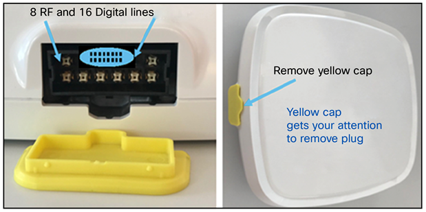
RP-TNC is the most popular RF connector and is found on the top of most access points. RP-SMA is a much smaller connector that doesn’t lend itself well to the use of thicker coaxial cables. N is an industry-standard connector used by professional installers. DART is an Amphenol trademark and is used in newer Cisco access point antenna designs (such as the Catalyst 9120AXE and 9130AXE) because it can pass along Self-Identifying Antenna (SIA) information and allows for a single insertion point for multiple antenna connections (with data lines). This single antenna connector dramatically reduces installation time and antenna installation errors.
A DART connector is a digital (16 lines) analog (either 4 or 8 RF connections) Radio Termination connector. DART-4 is used on the Cisco Aironet 3800e and Cisco Catalyst 9120AXE access points. DART-8 is used on the Cisco Catalyst 9130AXE access point. DART-4 and DART-8 are not interchangeable; refer to the approved antennas listed in the deployment guides. Note: DART connectors are also called smart connectors in the Cisco product literature.
Tip: The use of DART (smart) connectors and suitable antennas is defined in the Catalyst 9120AX and 9130AX Series deployment guides, which can be found at the links below.
Cisco Catalyst 9120AX Series Access Point Deployment Guide: https://www.cisco.com/c/en/us/products/collateral/wireless/catalyst-9100ax-access-points/guide-c07-742311.html
Cisco Catalyst 9130AX Series Access Point Deployment Guide: https://www.cisco.com/c/en/us/products/collateral/wireless/catalyst-9100ax-access-points/deployment-guide-c07-743490.html
Understanding self-identifying antennas
Starting with the Cisco 9120 Series Access Points, a new antenna referred to as a self-identifying antenna (SIA, typically indicated by a purple band) was introduced and contained circuitry to enable self-identification of the antenna by the Cisco Catalyst 9100 Access Points. There are several advantages to using an SIA:
● Access point hardware and software can sense the presence of the antenna and make decisions based on the same.
● An SIA provides software information elements such as the type and gain of the antenna.
● An SIA permits changes in the allowable Tx gain as the access point has confirmation as to the type of antenna being used.
● DART adapters have SIA information, allowing antennas with specific gains, such as 6 dBi or 13 dBi, to be used.
Two use cases for an SIA (and there are many) would be the following.
Overview: Previous products and newer access points that support external antennas like the Catalyst 9120AXE (without the detection of an SIA) would typically be hard-wired for a maximum gain of 6 dBi, so it wouldn’t matter if you attached a 2.2-dBi or 6-dBi antenna (the access point without SIA detection would set the Tx power for 6 dBi). So you would be slightly disadvantaged as to Tx power if you used an antenna with a gain lower than 6 dBi.
However, the integrated antenna models have always had embedded antennas with gains that do not change, as they are not removable, so the access point has always been optimized to the fixed gain of the embedded antennas. In the case of the Catalyst 9120AXI, it has an internal antenna of 4 dBi at 2.4 GHz and 5 dBi at 5 GHz, so the access point has been programmed to those embedded internal antenna gains for maximum RF power.
The adoption of SIA on access point models with external antennas remedies the 6-dBi cap by bringing the antenna gain more into parity with the actual antenna being used. If a dipole SIA (purple band) of, say, 2.2 dBi were connected to the access point, it would optimize RF power for 2.2 dBi.
Inversely, if a DART-8 adapter is used on the Catalyst 9130AXE (external antenna model) and the DART-8 adapter has an SIA value of 13 dBi, then a 13-dBi antenna could be connected to the DART connector, optimizing power for the same. DART adapters are available in 6 dBi (RP-TNC connector) or 13 dBi (N-type connector).
Prior to the introduction of SIA-enabled access points, Cisco had offered a “-P” model for professional installation (that was hard-coded for 13 dBi). Now this can be efficiently handled within the DART adapter or using an SIA-enabled antenna.
The use of DART (smart) connectors and SIA technology is unique to Cisco and brings value and flexibility beyond what is typically found in competitor-type products.
The following section is from the Cisco Catalyst 9130AX Series Access Point Getting Started Guide at https://www.cisco.com/c/en/us/td/docs/wireless/access_point/9130ax/quick/guide/ap9130ax-getstart.html.
Self-identifying antennas on the Catalyst 9130AXE
The Catalyst 9130AXE access point supports SIAs with 8-port DART connectors. When the 9130AXE access point is powered up with an 8-port DART SIA connected to it, the access point’s circuitry reads the EEPROM in the SIA. This enables the access point to automatically configure the antenna gain.
Antennas with RP-TNC and N-type connectors for the 9130AXE access point can be found in the “List of External Antennas Supported on C9130AXE” table at: https://www.cisco.com/c/en/us/td/docs/wireless/access_point/9130ax/quick/guide/ap9130ax-getstart.html#48142. These antennas can be connected to the 9130AXE using an AIR-CAB002-D8-R= (RP-TNC) or AIR-CAB003-D8-N= (N-type). When using the RP-TNC adapter, the 9130AXE sets the antenna gain to 6 dBi. When using the N-type adapter, the 9130AXE sets the antenna gain to 13 dBi.
When using either adapter, connectors A, B, C, and D provide dual-band functionality. Connectors E, F, G, and H provide 5-GHz functionality. Additionally, connector H connects to the Bluetooth low energy (BLE) radio. When using the breakout cables and connecting to legacy dual-band antennas, the BLE radio will experience the gain of that antenna at 2.4 GHz.
As an accessory, a 3-foot extension cable (AIR-CAB003-D8-D8=) is available for installations where a longer cable is required to connect the Catalyst 9130AXE with any of the supported SIAs.
Radio Frequency (RF) signals are subject to losses and gains as they pass from the transmitter through the cable to the antenna, through air (or solid obstruction), to the receiving antenna, cable, and receiving radio. Except for solid obstructions, most of these figures and factors are known and can be used in the design process to determine whether an RF system such as a WLAN will work.
The decibel (dB) scale is a logarithmic scale used to denote the ratio of one power value to another. For example: X1`dB = 10 log10 (Power A / Power B)
An increase of 3 dB indicates a doubling (2x) of power. An increase of 6 dB indicates a quadrupling (4x) of power. Conversely, a decrease of 3 dB reduces power by one-half, and a decrease of 6 dB results in one-fourth of the power. Some examples of decibel values and corresponding factors are shown in the table below.
Table 3. Decibel values and corresponding factors
| Increase |
Factor |
Decrease |
Factor |
| 0 dB |
1 x (same) |
0 dB |
1 x (same) |
| 1 dB |
1.25 x |
-1 dB |
0.8 x |
| 3 dB |
2 x |
-3 dB |
0.5 x |
| 6 dB |
4 x |
-6 dB |
0.25 x |
| 10 dB |
10 x |
-10 dB |
0.10 x |
| 12 dB |
16 x |
-12 dB |
0.06 x |
| 20 dB |
100 x |
-20 dB |
0.01 x |
| 30 dB |
1000 x |
-30 dB |
0.001 x |
| 40 dB |
10,000 x |
-40 dB |
0.0001 x |
WLAN equipment is usually specified in decibels compared to known values. Transmit power and receive sensitivity is specified in dBm, where “m” means 1 milliwatt (mW). So 0 dBm is equal to 1 mW, 3 dBm is equal to 2 mW, 6 dBm is equal to 4 mW, and so on, as shown in the table below.
Table 4. dBm to mW conversion
| Increase |
Factor |
Decrease |
Factor |
| 0 dBm |
1 mW |
0 dBm |
1 mW |
| 1 dBm |
1.25 mW |
-1 dBm |
0.8 mW |
| 3 dBm |
2 mW |
-3 dBm |
0.5 mW |
| 6 dBm |
4 mW |
-6 dBm |
0.25 mW |
| 7 dBm |
5 mW |
-7 dBm |
0.20 mW |
| 10 dBm |
10 mW |
-10 dBm |
0.10 mW |
| 12 dBm |
16 mW |
-12 dBm |
0.06 mW |
| 13 dBm |
20 mW |
-13 dBm |
0.05 mW |
| 15 dBm |
32 mW |
-15 dBm |
0.03 mW |
| 17 dBm |
50 mW |
-17 dBm |
0.02 mW |
| 20 dBm |
100 mW |
-20 dBm |
0.01 mW |
| 30 dBm |
1000 mW (1 W) |
-30 dBm |
0.001 mW |
| 40 dBm |
10,000 mW (10 W) |
-40 dBm |
0.0001 mW |
Isolation and access point placement
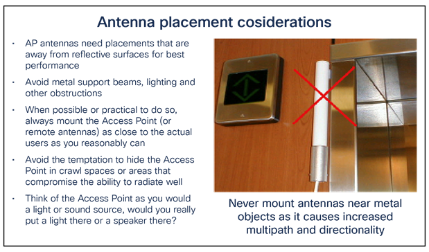
When mounting access points, it is recommended that you do not co-locate them near each other or other RF devices. Always try to keep at least a 2-meter distance between devices. Avoid mounting access points near metal objects, as the antennas are designed to be free from metal. Any metal object in the near field can affect the properties of the antenna, causing unwanted nulls (dead spots) and changing the characteristics of the radiated signal (perhaps adding unwanted directional properties).
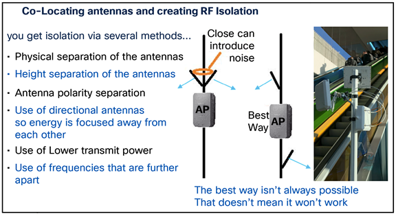
Sometimes, you must co-locate access points and/or antennas much closer than the recommended 2 meters. Perhaps you have only one mounting structure, or you are trying to set up a network where another already exists.
● Any co-located device is likely to work well with little or no utilization, so test any co-located devices with both devices operating at moderate to heavy load concurrently, then shut each unit off and measure performance without the co-location (that will tell you if co-locating is acceptable).
● If devices are similar (for example, access points), choose frequencies that are as far apart as possible. For example, use 2.4 GHz on one and 5 GHz on another, or use two 5 GHz (choosing channels that are as far apart as possible or practical).
● Try not to run the devices at full RF power; reducing power can help reduce retries.
● If the product supports directional antennas, try to use them (pointing each antenna away from the other device).
● If the product supports omnidirectional antennas, try to get some vertical space isolation (mounting one significantly higher than the other), or if it is a directional antenna, mount one antenna higher (in both cases, ideally on the same pole).
● Try to get some isolation with items in the near field (for example, a directional antenna on each side of, say, an I-beam.
● If outdoor or point-to-point, perhaps change polarity (with horizontal on one link, vertical on another),
Wi-Fi 6 antenna implementations using the Catalyst 9120AXE
The 9120AXE and 9130AXE are some of the most current access point designs that use the newer Wi-Fi 6 technology. The “AX” in the model number reflects the IEEE 802.11ax specification that Wi-Fi 6 (a simpler term the Wi-Fi alliance uses) is based upon.
Cisco chose two slightly different approaches in the design of these access points:
The Catalyst 9120AXE was designed to use standard dipoles (on top of the unit for dual-band operation and simplicity), but then presents a DART-4 connector on the side of the unit for more flexible antenna options should you choose to use the XOR feature of the access point to, say, create two different 5-GHz cells.
Wi-Fi 6 antenna implementations using the Catalyst 9130AXE
The Catalyst 9130AXE has no RP-TNC connectors and therefore does not have the support structure on top for dipoles. It was designed to hide the appearance of external antennas that typically hang down from the access point and to elegantly move those antenna connectors within a single connector for aesthetics and ease of installation. This also allows the 9130AXE, with its plenum UL2034 rating, to be placed above the ceiling, with the antenna co-located below it. The DART-8 (smart) adapters come in RP-TNC (6 dBi) and N-type (13 dBi) connectors.
The 9130AXE can run 5 GHz in 8x8 mode plus 2.4 GHz in 4x4 mode. It is really one of the most flexible and powerful Wi-Fi 6 access points on the market and one of the few that can support external antennas. The innovation of a single-insertion connector coupled with SIA functionality allows the 9130AXE to easily discover and configure different kinds of external antennas. In addition, there are several DART adapters for many standard antennas supporting RP-TNC and N-type connectors. Below are the three most popular single-insertion antennas for the 9130AXE.
Popular Wi-Fi 6 and 6E access point models and supported antennas
Cisco Catalyst 9130AXE
Cisco Catalyst 9130AX Series Access Points data sheet: https://www.cisco.com/c/en/us/support/wireless/catalyst-9130ax-series-access-points/series.html
Cisco Catalyst 9130AX Series Access Points Getting Started Guide (has an approved antenna list): https://www.cisco.com/c/en/us/td/docs/wireless/access_point/9130ax/quick/guide/ap9130ax-getstart.html
Cisco Catalyst 9130 Series Access Point Deployment Guide: https://www.cisco.com/c/en/us/products/collateral/wireless/catalyst-9100ax-access-points/deployment-guide-c07-743490.html
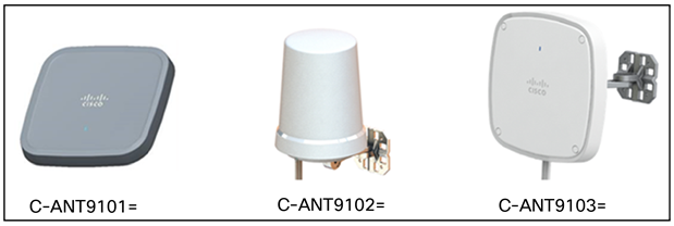
There are three antennas with SIA functionality expressly designed for this model that can be used without the need for adapter cables. The data sheets and patterns can be found at the following URLs:
● C-ANT9101= Omnidirectional Ceiling Mount Antenna, 2 dBi (2.4 GHz) and 6 dBi (5 GHz): https://www.cisco.com/c/en/us/td/docs/wireless/antenna/installation/guide/ant9101.html
● C-ANT9102= Omnidirectional Wall-Mount Antenna, 4 dBi (2.4 GHz) and 4 dBi (5 GHz): https://www.cisco.com/c/en/us/td/docs/wireless/antenna/installation/guide/ant9102.html
● C-ANT9103= Directional Patch Antenna, 6 dBi (2.4 GHz) and 6 dBi (5 GHz): https://www.cisco.com/c/en/us/td/docs/wireless/antenna/installation/guide/ant9103.html
Other legacy antennas may also be used with the DART adapters:
● Cisco AIR-CAB-002-D8-R= connector for conventional antennas up to 6 dBi with RP-TNC connectors
● Cisco AIR-CAB-003-D8-N= for conventional antennas up to 13 dBi with N-type connectors
● Cisco AIR-CAB-003-D8-D8= a 3-foot extension cable (DART male to female with right-angle connector)
Legacy antennas supported using the DART adapters above
The non-DART-based SIAs below are not detected as SIAs. They use the SIA in the DART adapter to determine gain. Also, dipoles are not supported, as there is no mounting structure to support this.
● AIR-ANT2513P4M-N=. Patch antenna, 4 ports, with N-type connectors, 13 dBi (2.4 GHz) and 13 dBi (5 GHz) https://www.cisco.com/c/en/us/td/docs/wireless/antenna/installation/guide/ant2513p4mn.html
● AIR-ANT2524V4C-R= and AIR-ANT2524V4C-RS=. Ceiling-mount omni antenna, 4 ports, with RP-TNC connectors, 2 dBi (2.4 GHz) and 4 dBi (5 GHz) https://www.cisco.com/c/en/us/td/docs/routers/connectedgrid/antennas/installing-combined/b-cisco-industrial-routers-and-industrial-wireless-access-points-antenna-guide/m-air-ant2524v4c-r.html
● AIR-ANT2544V4M-R= and AIR-ANT2544V4M-RS=. Wall-mount omni antenna, 4 ports, with RP-TNC connectors. 4 dBi (2.4 GHz) and 4 dBi (5 GHz) https://www.cisco.com/c/en/us/td/docs/wireless/antenna/installation/guide/ant2544v4m-r.html
● AIR-ANT2566D4M-R= and AIR-ANT2566D4M-RS=. 60° patch antenna, 4 ports, with RP-TNC connectors, 6 dBi (2.4 GHz) and 6 dBi (5 GHz) https://www.cisco.com/c/en/us/td/docs/wireless/antenna/installation/guide/ant2566d4m.html
● AIR-ANT2566P4W-R= and AIR-ANT2566P4W-RS=. Directional antenna, 4 ports, with RP-TNC connectors, 6 dBi (2.4 GHz) and 6 dBi (5 GHz) https://www.cisco.com/c/en/us/td/docs/wireless/antenna/installation/guide/ant2566p4w.pdf
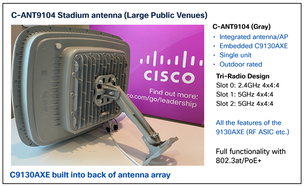
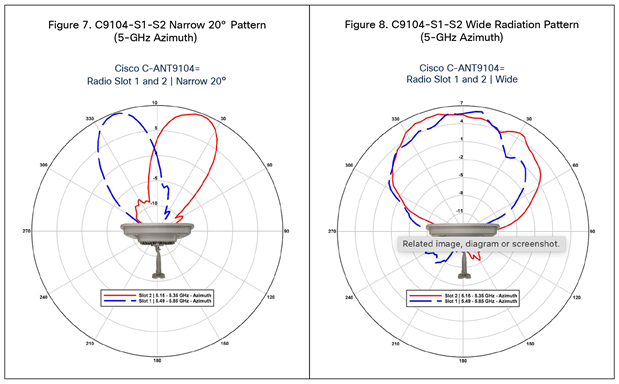
Cisco Catalyst 9130 with 9104 stadium antenna (C-ANT9104)
Cisco Catalyst 9104 stadium antenna plus access point data sheet and installation guide: https://www.cisco.com/c/en/us/td/docs/wireless/antenna/installation/guide/b-ant9104ax_ig/introduction.html
Tip: Unlike the 9130AXE access point (without the 9104 antenna), when the 9130AXE is integrated into the 9104 antenna, the 5-GHz radios are band-locked (for RF isolation), so local regulations for outdoor use should be checked to confirm that both radios will be allowable.
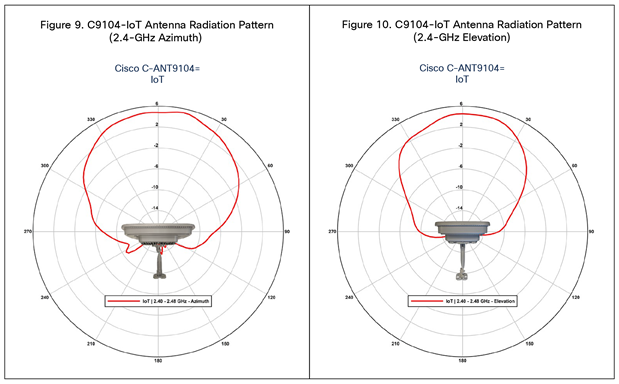
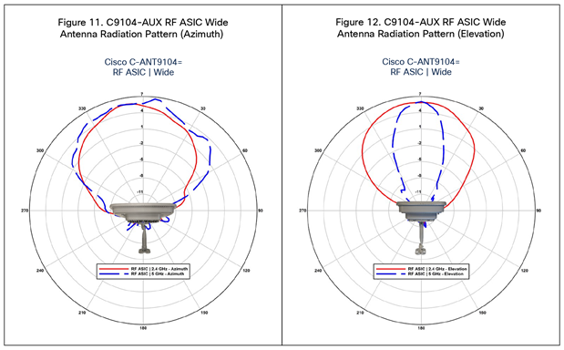
This antenna is 6 dBi at 2.4 GHz, 7 dBi wide beamwidth at 5 GHz, 10 dBi narrow beamwidth at 5 GHz, and 6 dBi IoT at 2.4 GHz.
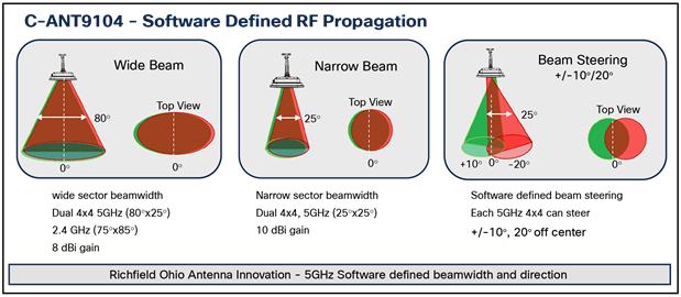
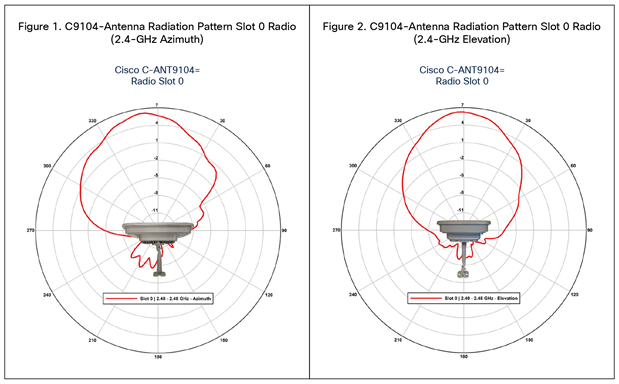
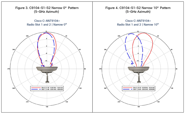
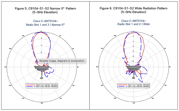
C-ANT9104 azimuth and elevation radiation patterns
Cisco Catalyst 9120AXE and 9120AXP
Cisco Catalyst 9120AX Series Access Point data sheet: https://www.cisco.com/c/en/us/products/collateral/wireless/catalyst-9120ax-series-access-points/datasheet-c78-742115.html
Cisco Catalyst 9120AX Series Access Point Getting Started Guide (approved antenna list): https://www.cisco.com/c/en/us/td/docs/wireless/access_point/9120ax/quick/guide/ap9120ax-getstart.html
Cisco Catalyst 9120 Access Point Deployment Guide: https://www.cisco.com/c/en/us/products/collateral/wireless/catalyst-9100ax-access-points/guide-c07-742311.html.
Three antennas are used with the newer 9130AXE: C-ANT9101=, C-ANT9102=, and C-ANT9103=. These antennas use a DART-8 connector and therefore are not compatible with the Catalyst 9120AX Series access points, as the 9120AXE uses a DART-4 connector on the side for dual 5-GHz operation and RP-TNC connectors on the top for dual-band operation.
Supported antennas for use with the 9120AXE and 9120AXP:
● AIR-ANT2524DB-R=, AIR-ANT2524DG-R=, AIR-ANT2524DW-R=, and AIR-ANT2524DW-RS. Dipole (black, gray, white, and white with SIA) with RP-TNC connectors, 2 dBi (2.4 GHz) and 4 dBi (5 GHz) https://www.cisco.com/c/en/us/td/docs/wireless/antenna/installation/guide/ant2524.html
● AIR-ANT2535SDW-R and AIR-ANT2535SDW-RS. Dual-band low-profile white mono pole similar in appearance to a dipole but physically smaller. Uses the metal access point as the ground plane. https://www.cisco.com/c/en/us/td/docs/wireless/antenna/installation/guide/ant2535sdwr.html
● AIR-ANT2524V4C-R= and AIR-ANT2524V4C-RS=. Ceiling-mount omni antenna, 4 ports, with RP-TNC connectors, 2 dBi (2.4 GHz) and 4 dBi (5 GHz) https://www.cisco.com/c/en/us/td/docs/routers/connectedgrid/antennas/installing-combined/b-cisco-industrial-routers-and-industrial-wireless-access-points-antenna-guide/m-air-ant2524v4c-r.html
● AIR-ANT2544V4M-R= and AIR-ANT2544V4M-RS=. Wall-mount omni antenna, 4 ports, with RP-TNC connectors, 4 dBi (2.4 GHz) and 4 dBi (5 GHz) https://www.cisco.com/c/en/us/td/docs/wireless/antenna/installation/guide/ant2544v4m-r.html
● AIR-ANT2566D4M-R= and AIR-ANT2566D4M-RS=. 60° patch antenna, 4 ports, with RP-TNC connectors, 6 dBi (2.4 GHz) and 6 dBi (5 GHz) https://www.cisco.com/c/en/us/td/docs/wireless/antenna/installation/guide/ant2566d4m.html
● AIR-ANT2566P4W-R= and AIR-ANT2566P4W-RS=. Directional antenna, 4 ports, with RP-TNC connectors, 6 dBi (2.4 GHz) and 6 dBi (5 GHz) https://www.cisco.com/c/en/us/td/docs/wireless/antenna/installation/guide/ant2566p4w.pdf
● AIR-ANT2513P4M-N=. Patch antenna, 4 ports, with N-type connectors, 13 dBi (2.4 GHz) and 13 dBi (5 GHz) https://www.cisco.com/c/en/us/td/docs/wireless/antenna/installation/guide/ant2513p4mn.html
This antenna is for use only with the Catalyst 9120AXP (professional installation).
The secondary 5-GHz radio is on the DART connector. If used, the antenna should have a DART-4 connector; otherwise, a DART-4 adapter, AIR-CAB002-DART-R=, should be used.
Other antennas and accessories (Aironet and Catalyst) can be viewed at the Cisco Aironet and Catalyst Antennas and Accessories Reference Guide: https://www.cisco.com/c/en/us/products/collateral/wireless/aironet-antennas-accessories/product_data_sheet09186a008008883b.html
Cisco Catalyst 9124 Outdoor Access Point
Cisco Catalyst 9124 Series Access Points data sheet: https://www.cisco.com/c/en/us/products/collateral/wireless/catalyst-9100ax-access-points/nb-06-cat9124-ser-ap-ds-cte-en.html
Cisco Catalyst 9124 Series Access Points Hardware Installation Guide: https://www.cisco.com/c/en/us/td/docs/wireless/access_point/9124ax/install-guide/b-hig-9124ax.html
Cisco Catalyst 9124AX Series Outdoor Access Point is a Wi-Fi 6 technology based outdoor access point. This access point (AP) series has three models:
● Cisco Catalyst 9124AXI AP with omni antennas
● Cisco Catalyst 9124AXD AP with directional antennas
● Cisco Catalyst 9124AXE AP with external antennas
This AP series support the following Wi-Fi 6 features:
● 4x4:4SS on the 2.4-GHz and 5-GHz bands
● Orthogonal Frequency Division Multiple Access (OFDMA) on downlink and uplink supported
● Multi-User, Multiple Input, Multiple Output (MU-MIMO)
The Cisco Catalyst 9124AX Series Outdoor Access Point configurations are:
● C9124AXI-x
● C9124AXD-x
● C9124AXE-x
Antenna and Radios
The C9124AXI-x and 9124AXD-x AP models have four internal dual-band antennas with dedicated 2.4-GHz and 5-GHz radios, one internal single-band antenna with a dedicated 2.4-GHz IoT radio, and two dual-band antennas with a dedicated 2.4-GHz and 5-GHz AUX radio.
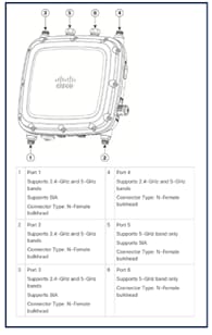
The C9124AXE-x AP model has six antenna ports to support multiple antenna options, such as the self-identifying antennas (SIA) on designated three SIA ports, dual-band antennas, and single-band antennas. To see the list of supported antennas and the radio bands they operate at, see the Supported External Antennas section.
The C9124AXE-x AP model supports 1 to 6 antenna configurations for the 2.4GHz and 5GHz radios. In addition, the IoT radio has its separate internal antenna, and Aux radio shares the same antennas with serving radios through splitters.
The C9124AXE supports a Dual Radio mode and a dynamic Tri-Radio mode.
C9124AXE in Dual Radio mode:
● 2.4GHz and 5GHz 802.11ax concurrent radios
● 2G - 4TX x 4RX; four spatial streams
● 5G - 4TX x 4RX; four spatial streams (2SS for 80+80 contiguous channel)
The C9124AXE in Tri-Radio mode:
● 5G Radio1 - 2TX x 2RX; 2SS for channel bandwidth <= 80MHz
● 5G Radio2 - 2TX x 2RX; 2SS for channel bandwidth <= 80MHz
● 2G Radio - 2TX x 2RX; 2SS for 20 MHz only
C9124AXE Port Configurations
C9124AXE Supported Antenna
Table 5. dBm to mW conversion
| PID |
Antenna Gain (dBi) |
Antenna Name |
|
|
|
2.4–GHz |
5–GHz |
|
| AIR-ANT2547V-N |
4 |
7 |
Cisco Aironet Dual-Band Omnidirectional Colinear Array Antenna (White) Connectors: N-Male |
| AIR-ANT2547VG-N |
4 |
7 |
Cisco Aironet Dual-Band Omnidirectional Colinear Array Antenna (Gray) Connectors: N-Male |
| AIR-ANT2547VG-NS |
4 |
7 |
Cisco Aironet Dual-Band Omnidirectional Colinear Array (Gray), Self-Identifying Antenna Connectors: N-Male |
| AIR-ANT2588P4M-NS= |
8 |
8 |
Cisco Aironet 2.4–GHz/5–GHz 8–dBi 4-Element Dual-Polarized Patch Self-Identifying Antenna Connectors: N-Female Bulkhead |
| AIR-ANT2450V-N= |
5 |
— |
Cisco Aironet 5–dBi Omnidirectional Antenna |
| AIR-ANT2480V-N= |
8 |
— |
Cisco Aironet 8–dBi Omnidirectional Antenna |
| AIR-ANT2413P2M-N= |
13 |
— |
Cisco Aironet 2.4–GHz 13–dBi Directional Antenna |
| AIR-ANT2413P2M-NS= |
13 |
— |
Cisco Aironet 2.4–GHz 13–dBi Directional Antenna, Self-Identifying |
| AIR-ANT5180V-N= |
— |
8 |
Cisco Aironet 8–dBi Omnidirectional Antenna |
| AIR-ANT5114P2M-N= |
— |
14 |
Cisco Aironet 5–GHz 14–dBi Directional Antenna |
| AIR-ANT5114P2M-NS= |
— |
14 |
Cisco Aironet 5–GHz 14–dBi Directional Antenna, Self-Identifying |
| AIR-ANT2568VG-N |
6 |
8 |
Cisco Aironet Dual-Band Omnidirectional Antenna |
| AIR-ANT2568VG-NS |
6 |
8 |
Cisco Aironet Dual-Band Omnidirectional Antenna, Self-Identifying |
| AIR-ANT2513P4M-N= |
13 |
13 |
Cisco Aironet Four-Port Dual-Band Polarization-Diverse Array Antenna |
| AIR-ANT2513P4M-NS= |
13 |
13 |
Cisco Aironet Four-Port Dual-Band Polarization-Diverse Array Antenna, Self-Identifying |
To know more about the RF Patterns of these Antenna, refer to this guide,
Cisco Catalyst 9166I and 9166D1 (Cisco and Meraki)
Cisco Catalyst 9166 Series Access Points data sheet: https://www.cisco.com/c/en/us/products/collateral/wireless/catalyst-9166-series-access-points/catalyst-9166-series-access-points-ds.html.
Cisco Catalyst 9166D1 Access Point Deployment Guide: https://www.cisco.com/c/en/us/products/collateral/wireless/catalyst-9164-series-access-points/catalyst-9166i-9164i-dg.html.
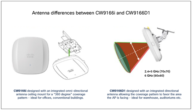
The Cisco Catalyst 9166D1 is very similar to the Catalyst 9166I; the internal hardware features and functionality are essentially the same, with a few features added that we will discuss later in this guide. The takeaway is that the 9166I has an omnidirectional antenna, and the CW9166D1 has an integrated directional antenna array.
This internal directional antenna differs slightly from previous directional access point products that used external (removable) antennas. This difference is due mostly to regulatory constraints placed upon products operating using 6 GHz (Wi-Fi 6E), especially when the product (in the U.S.) covers the entire 6-GHz spectrum and when the desire is to focus the access point’s energy in a given direction.
Tip: It is important to note that in countries that do not currently support standard power and AFC, external antennas are not permitted, so the 9166D1 explicitly addresses deployments that would have previously (2.4 and 5 GHz) used external directional antennas.
Cisco Catalyst 9163E (Cisco and Meraki) Wi-Fi 6E supported
The Cisco Catalyst 9163E is an outdoor-rated, enterprise-class 802.11ax cloud-managed access point. The access point has tri-band concurrent radios geared toward low- to medium-density applications. It will work with different external antennas for required directivity.
It features 2x2 tri-band traffic radios (2x2 at 2.4 GHz plus 2x2 at 5 GHz plus 2x2 at 6 GHz), a 1x1 tri-band scanning radio, and a 2.4-GHz IoT radio for BLE, Zigbee, Thread, etc. It also has a built-in GNSS receiver for 6-GHz AFC compliance.
This access point initially supports an omnidirectional and GPS/GNSS antenna. This is an early look and is subject to change. Check the released documentation when available. Additionally, a tri-band directional antenna will be available. Part numbers break down like this: CW (Cisco Wireless) ANT (antenna) O1 (omni) D1 (directional) NS (N-type connector supporting SIA mode).
If you choose to deploy without 6 GHz (meaning 6 GHz is disabled in software), you should either install 6-GHz antennas so 6 GHz will be available when you choose to enable it or cap the two N-type connectors using suitable weatherproofing or Cisco N-type weatherized caps (AIR-ACC15-N-CAP=).
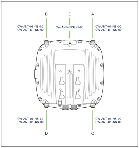
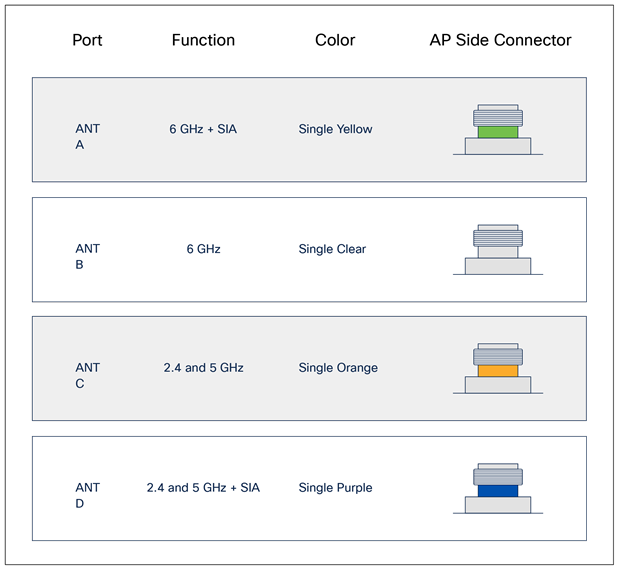
At the time of this writing, this product is just being released. More data will be available online; however, at the initial release, these are the antenna part numbers that should be available:
● CW-ANT-01-NS-00. Tri-band omnidirectional antenna with N-type connector (directly attached).
● CW-ANT-D1-NS-00. Tri-band patch, two 2.4-/5-GHz dual-band ports, and two 5-/6-GHz ports (total 4 antenna ports) with a cable that matches the color scheme in the figure above.
● CW-ANT-GPS2-00. L1/L5 dual-band RHCP GNSS antenna (active).
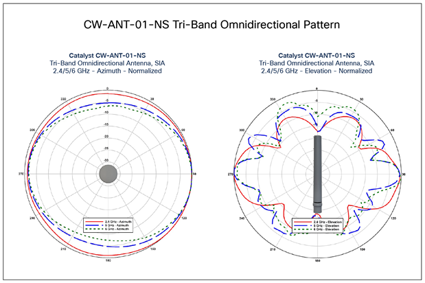
Cisco Meraki access points with external antenna support
Cisco Meraki outdoor access points (including the MR74, MR76, MR84, and MR86) and specific indoor access points (MR42E, MR53E, and MR46E) support external antennas to focus their signal into a particular coverage pattern.
Cisco Meraki antennas come in three types (omni, patch, and sector antennas). In addition, there are band-specific antennas and dual-band antennas. Omnidirectional antennas are designed to radiate (and collect) RF signals 360 degrees around the access point in the horizontal plane.
Directional antennas focus the RF energy into a smaller coverage area. They are not “amplifying” the signal but provide passive gain to project the signal farther in one direction (as well as collect signals from clients farther away in the same direction). Sector antennas focus the RF energy into a cone shape, whereas a patch antenna tends to be a more giant cone or almost hemispherical.
The Meraki outdoor MA-ANT-20 is a dual-band omnidirectional antenna that appears cylindrical and supports both 2.4- and 5-GHz bands, with a signal that radiates evenly in a 360-degree horizontal pattern around the antenna. These antennas are typically used on access points for client association due to the evenly distributed signal pattern.
Patch and sector antennas are flat and either square or rectangular, and the RF signals are radiated and collected on the flat front surface of the antenna housing. Patch and sector antennas can be a single band, such as the 5-GHz MA-ANT-21 or 2.4-GHz MA-ANT-23, or dual-band, such as the MA-ANT-25 patch or MA-ANT-27 sector antenna.
Patch and sector antennas focus the RF energy in a particular direction. Typically, a sector antenna is more focused than a patch antenna and can transmit a signal farther away and “hear” signals from farther away. These are commonly used to serve clients gathered in a particular direction instead of evenly spread around the access point. Patch and sector antennas are also often used for wireless mesh connections or other point-to-point wireless links, since the signal is focused in a single direction for longer-distance links.
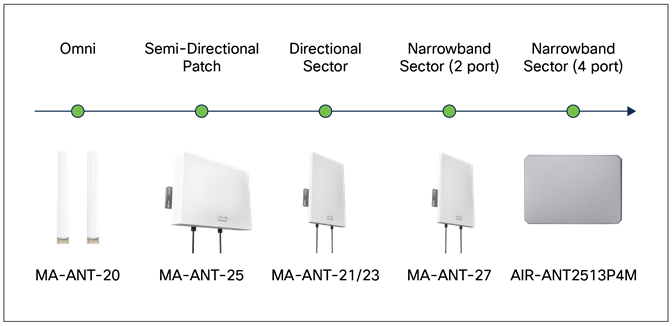
Table 6. Current list of approved Meraki antennas for outdoor Meraki access points
| Antenna SKU |
Type |
Band(s) |
2.4 GHz Gain |
5 GHz Gain |
Density |
Half Power Beamwidth |
| MA-ANT-20 |
Omni |
Dual |
4 dBi |
7 dBi |
Any |
H: 360° V: 45° |
| MA-ANT-21 |
Sector |
5 GHz |
N/A |
13 dBi |
High |
H: 80° V: 30° |
| MA-ANT-23 |
Sector |
2.4 GHz |
11 dBi |
N/A |
High |
H: 70° V: 40° |
| MA-ANT-25 |
Patch |
Dual |
8 dBi |
6.5 dBi |
Medium/High |
H: 60°/75° V: 70°/84° |
| MA-ANT-27 |
Sector |
Dual |
9 dBi |
12 dBi |
High |
H: 86°/65° V: 34°/18° |
| AIR-ANT2513P4M-N |
Patch |
Dual |
13 dBi |
13 dBi |
Very High |
H: 31°/31° V: 33°/27° |
* Half Power (-3dB) Beam Width listed for both horizontal (azimuth) and vertical (elevation).
* Number pairs such as 60°/75° are listed as 24GHz value / 5Ghz value.
Outdoor Meraki antennas for use with MR74, MR76, MR84, and MR86 access points
● Meraki MA-ANT-20. Dual-band omni, 4 dBi (2.4 GHz) and 7 dBi (5 GHz).
Data sheet: https://meraki.cisco.com/product-collateral/dual-band-omni-antennas-4-7-dbi-datasheet/?file
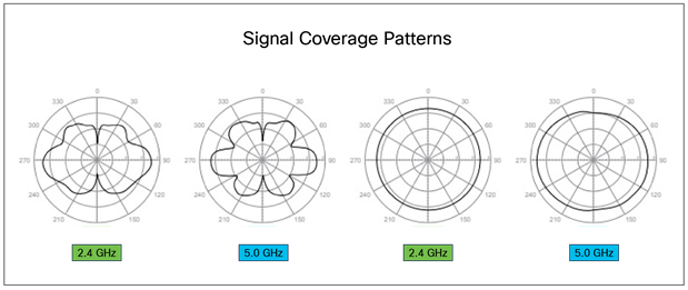
● Meraki MA-ANT-21 directional sector antenna with N-type connectors, 13 dBi (5 GHz)
Data sheet: https://meraki.cisco.com/lib/pdf/meraki_datasheet_antenna_5GHz_sector_13dBi.pdf
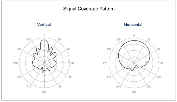
● Meraki MA-ANT-23 directional sector antenna with N-type connectors, 11 dBi (2.4 GHz)
Data sheet: https://meraki.cisco.com/lib/pdf/meraki_datasheet_antenna_2GHz_sector_11dBi.pdf
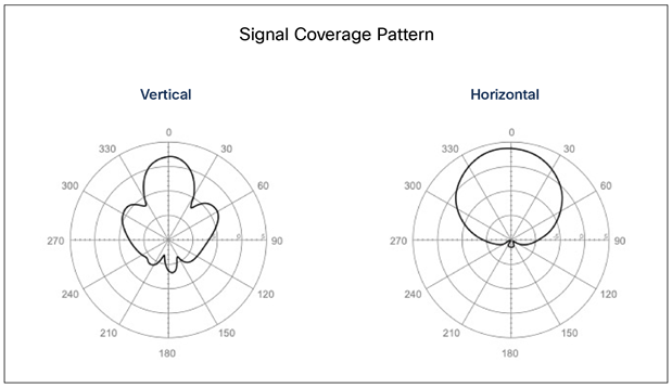
● Meraki MA-ANT-25 dual-band patch with N-type connectors, 8 dBi (2.4 GHz) and 6.5 dBi (5 GHz)
Data sheet: https://meraki.cisco.com/product-collateral/ma-ant-25-datasheet/?file
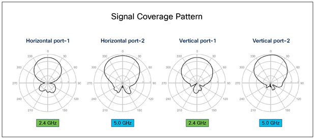
● Meraki MA-ANT-27 dual-band sector with N-type connectors, 9 dBi (2.4 GHz) and 12 dBi (5 GHz)
Data sheet: https://meraki.cisco.com/product-collateral/dual-band-sector-antenna-datasheet/?file
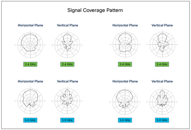
Indoor Meraki antennas for use with Meraki MR53E and MR46E
Indoor access points (MR42E, MR53E, and MR46E) support the following antennas.
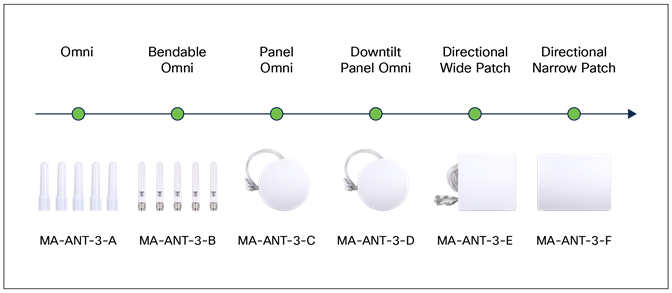
● MA-ANT-3-A5/6 straight dipole antenna, 3.8 dBi (2.4 GHz) and 5.5 dBi (5 GHz)
Data sheet: https://meraki.cisco.com/lib/pdf/meraki_datasheet_MA-ANT-3-A.pdf
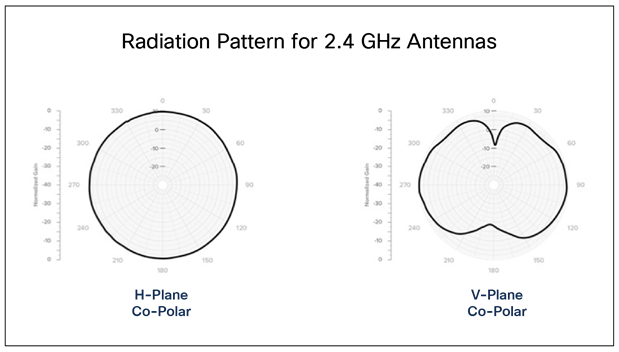
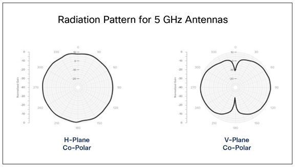
● MA-ANT-3-B5/6 swivel dipole antenna, 3 dBi (2.4 GHz) and 5.7 dBi (5 GHz)
Data sheet: https://meraki.cisco.com/lib/pdf/meraki_datasheet_MA-ANT-3-B.pdf
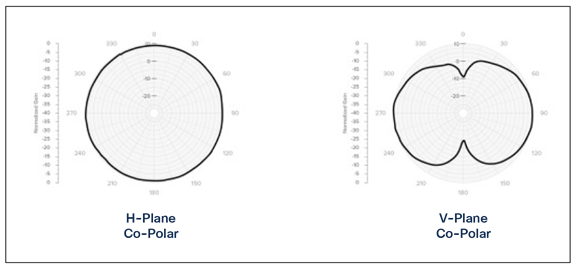
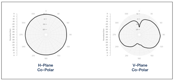
● MA-ANT-3-C5/6 ceiling-mount omni, 4.9 dBi (2.4 GHz) and 4.9 dBi (5 GHz)
Data sheet: https://meraki.cisco.com/lib/pdf/meraki_datasheet_MA-ANT-3-C.pdf

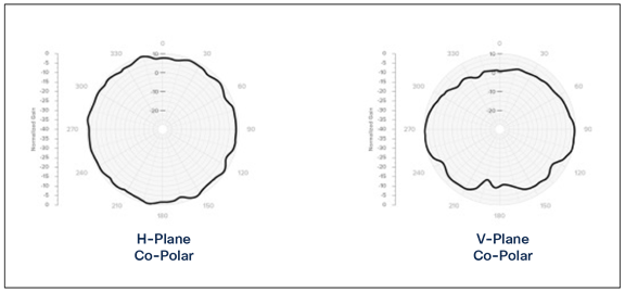
● MA-ANT-3-D5/6 omni with down-tilt, 2.4 dBi (2.4 GHz) and 3.7 dBi (5 GHz)
Data sheet: https://meraki.cisco.com/product-collateral/downtilt-panel-omni-antenna-datasheet/?file
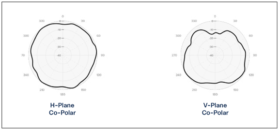
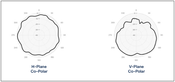
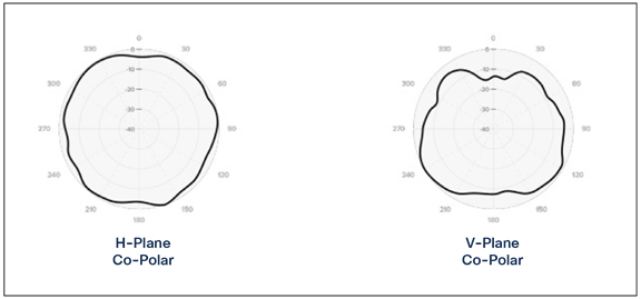
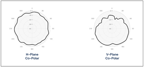
● MA-ANT-3-E5/6 wall-mount patch (wide), 7 dBi (2.4 GHz) and 6.3 dBi (5 GHz)
Data sheet: https://meraki.cisco.com/lib/pdf/meraki_datasheet_MA-ANT-3-E.pdf
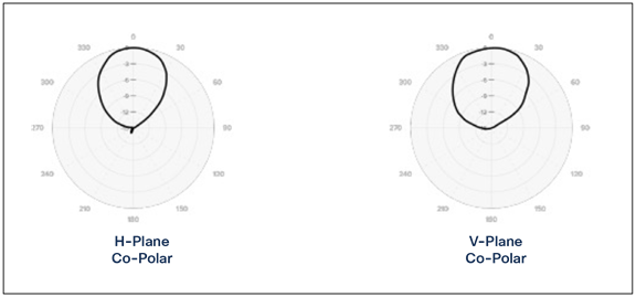
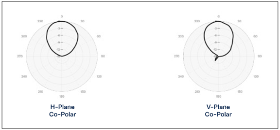
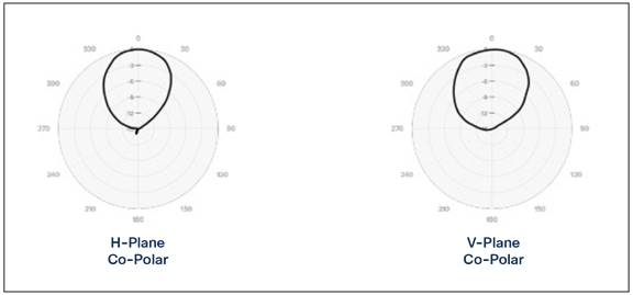
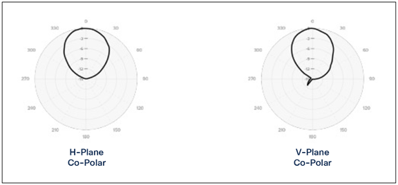
● MA-ANT-3-F5/6 wall-mount patch (narrow), 11.2 dBi (2.4 GHz) and 10.8 dBi (5 GHz)
Data sheet: https://meraki.cisco.com/product-collateral/narrow-patch-antenna-datasheet/?file
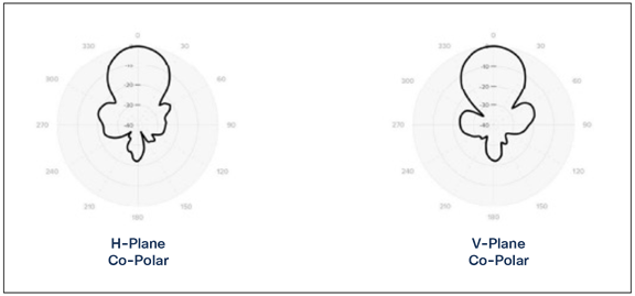
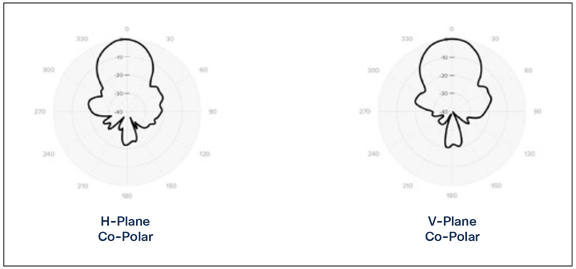
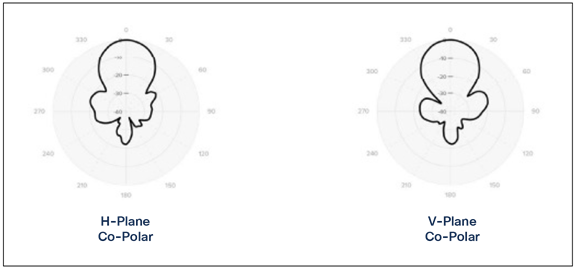
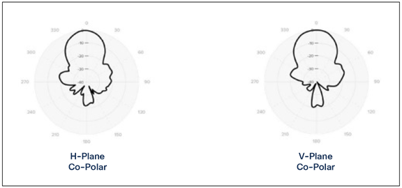
Considerations when access points are used outdoors (lighting and weather concerns)
Anytime an access point or antenna is located outdoors, here are a few things to consider:
● If the access point is outdoors, it is subject to corrosion—antenna and Ethernet connections, as well as mechanical mounting solutions, can be affected over time. If near the ocean, salt water can also be a concern.
● Moldable sealants such as Coax-seal or 3M’s Temflex 2155 can be used to weatherproof coaxial and Ethernet connections. For a tutorial, see “Weatherproof and UV Protect Your Coax Cable Connector” (video): https://www.youtube.com/watch?v=CcHiHCw0lsY.
● Rainwater can often hit a cable and “ride down the cable,” so consider adding a drip loop to ensure that water cannot run down into the RF or Ethernet connectors.
● Any cables entering a building (Ethernet or antenna) should have lighting arrestor(s) connected to a suitable ground before entering the building. Some fire and insurance codes require this, and to be clear, the goal is really to protect the building and IT equipment from damage; the outdoor product is secondary.
● If the entire unit is self-contained and located outdoors, lighting arrestors are less important, but the Ethernet cable feeding the device should be the type that is shielded, and lighting protection becomes a concern at the point the Ethernet cable enters the building. An Ethernet lighting arrestor should be used. Some customers convert the Ethernet to fiber where it enters the building, as fiber is not conductive.
● No amount of protection will keep your equipment completely safe from a direct lightning strike. Lighting protection helps by draining off charges from static created by wind, nearby strikes, etc.
● A system should be installed to be taken apart later, so mounting hardware should be stainless steel when possible. If not possible, apply a dielectric grease. A popular material is Super Lube: https://www.super-lube.com/silicone-dielectric-grease-91003.
● If Ethernet cables have long runs indoors, the cable should be plenum-rated above ceiling tiles and shielded if going over light fixtures and other areas where noise might be present.
● If the product uses electricity directly from, say, an outdoor light pole, good practices such as installing circuit breaker protection or other methods of disconnect should be considered.
● All mounting hardware should be secured well to withstand the elements, and perhaps the owner’s contact information should be attached to the installation if it is in a shared or multitenant location.
Configuring the network for 6-GHz operation
Catalyst configuration
Different options are available; here are a few popular methods.
Option 1: Pure WPA3
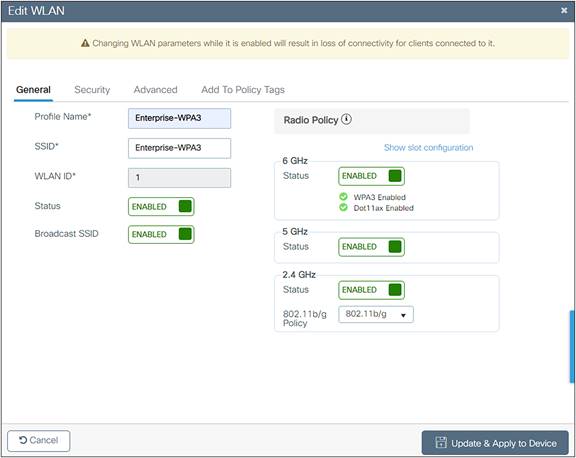

Pros: Single SSID, roaming bandwidth bands are supported, highly secure.
Cons: May not fit in an environment where legacy devices are more pervasive.
Option 1 alternative: Pure WPA3 – Fast Transition
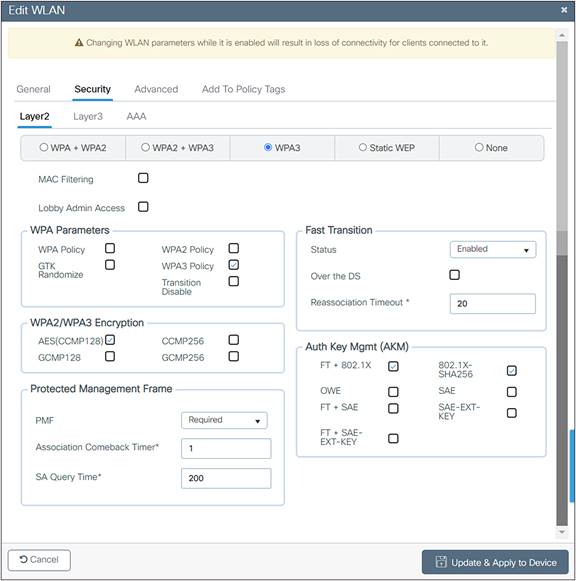
Option 2: Legacy-friendly 2.4/5-GHz profile 1
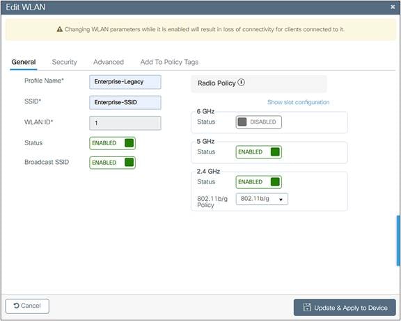
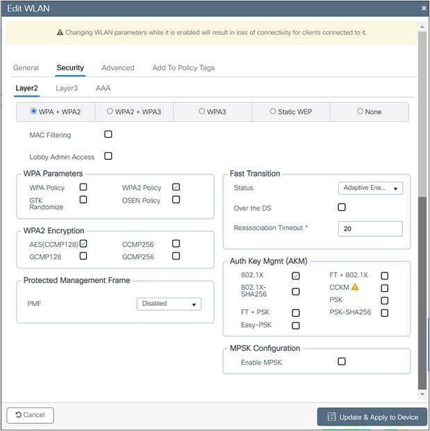
Option 2: Legacy-friendly 6-GHz profile 2
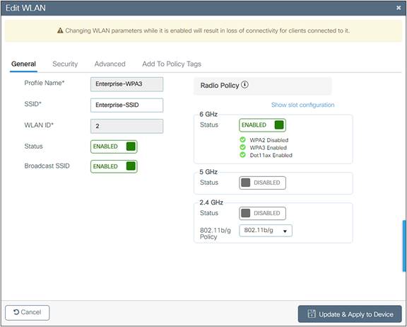
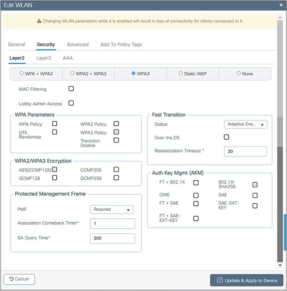
Pros: Can accommodate legacy clients, benefits Eduroam deployments.
Cons: Multiple profiles, roaming bandwidth bands are full roam.
Option 2 alternative: Legacy-friendly Fast Transition – 2.4/5-GHz profile 1
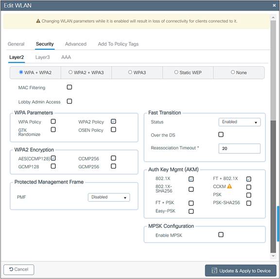
Option 2: Legacy-friendly Fast Transition – 6-GHz profile 2

Option 3: Transition mode
Starting from Cisco IOS XE version 17.12.x, we can use Transition mode with 6 GHz enabled.
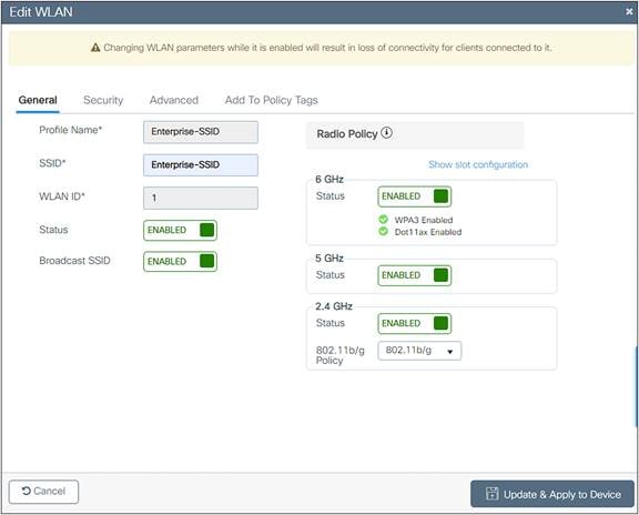
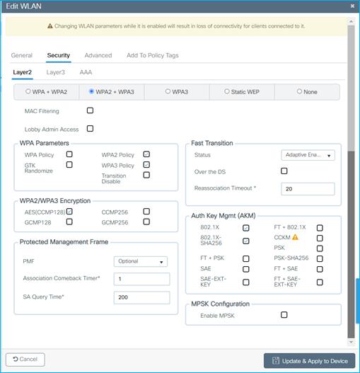
Transition mode, Security tab
Pros: Single SSID, single profile, roaming bandwidth bands are supported (WPA3 authentication and key management).
Option 3 alternative: Transition Mode ‒ Fast Transition
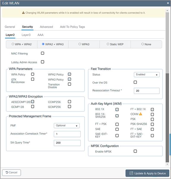
Meraki Enterprise
Option 1:
Reconfigure the existing SSID to meet Wi-Fi 6E requirements (WPA3 and Protected Management Frames [PMF]). Single SSID with WPA3 only selected.
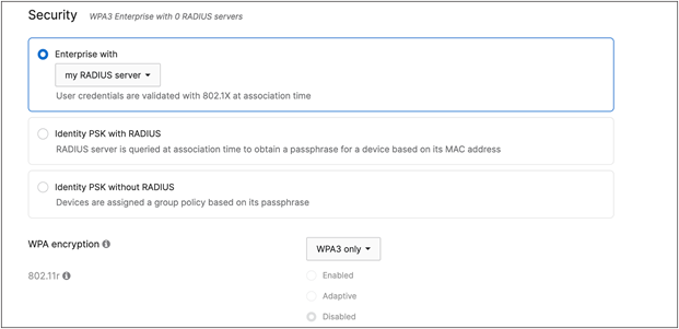
Option 2:
Add a separate WLAN with a different SSID name for WPA3 and broadcast it in all bands. Leave the existing WLAN/SSID untouched.
Legacy SSID: Existing WPA2 SSID in 2.4 and 5 GHz for legacy clients.
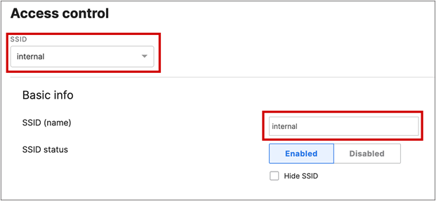
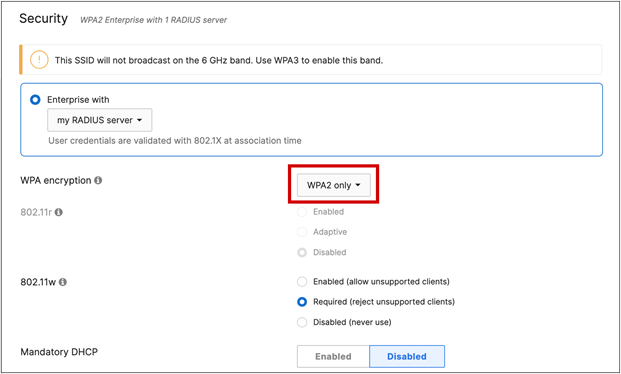
Dedicated SSID (use a new name) for WPA3-capable clients in all bands. This is the SSID for 6 GHz.
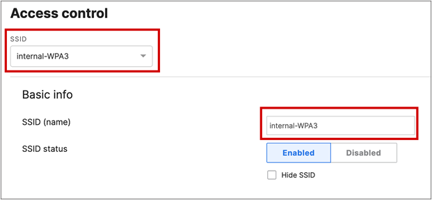
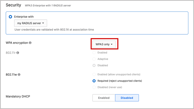
Meraki: Best Practice Design ‒ MR Wireless (August 2023): https://documentation.meraki.com/Architectures_and_Best_Practices/Cisco_Meraki_Best_Practice_Design/Best_Practice_Design_-_MR_Wireless
Cisco: Enterprise Mobility 8.5 Design Guide (November 2020): https://www.cisco.com/c/en/us/td/docs/wireless/controller/8-5/Enterprise-Mobility-8-5-Design-Guide/Enterprise_Mobility_8-5_Deployment_Guide.pdf
Cisco: 6 GHz Planning (January 2023): https://www.youtube.com/watch?v=0KmHCZy3PnY
Meraki: High-Density Wi-Fi Deployments Design Guide (October 2023): https://documentation.meraki.com/Architectures_and_Best_Practices/Cisco_Meraki_Best_Practice_Design/Best_Practice_Design_-_MR_Wireless/High_Density_Wi-Fi_Deployments
Cisco: Wireless High Client Density Design Guide (July 2018): https://www.cisco.com/c/en/us/td/docs/wireless/controller/technotes/8-7/b_wireless_high_client_density_design_guide.pdf
Cisco: All wireless products, including outdoor and industrial wireless: https://www.cisco.com/c/en/us/products/wireless/product-listing.html
Meraki: Wireless product catalog: https://meraki.cisco.com/product-catalog/wi-fi/
6-GHz Unlicensed Spectrum Regulations and Deployment Options White Paper (March 2023): https://www.cisco.com/c/en/us/products/collateral/wireless/catalyst-9100ax-access-points/ghz-unlicensed-spectrum-reg-wp.html
Mobility Field Day: 6 GHz and Beyond ‒ Catalyst and Meraki (video, November 2023): https://www.youtube.com/watch?v=BgpmFmsHS_I
The State of 6 GHz – Mobility Field Day Discussion (video, May 2023): https://www.youtube.com/watch?v=Ny0t-WiLk70
IEEE: The Evolution of Wi-Fi Technology and Standards (May 2023): https://standards.ieee.org/beyond-standards/the-evolution-of-wi-fi-technology-and-standards/
Overview – Technical white paper on 802.11ac (Wi-Fi 5): https://www.cisco.com/c/dam/en/us/products/collateral/wireless/aironet-3600-series/white-paper-c11-713103.pdf
Wi-Fi Alliance – Who We Are: https://www.wi-fi.org/who-we-are
WPA3 Deployment Guide (December 2023): https://www.cisco.com/c/en/us/td/docs/wireless/controller/9800/technical-reference/wpa3-dg.html
Cisco Aironet and Catalyst Antennas and Accessories Reference Guide ‒ has Cisco antenna patterns (November 2022): https://www.cisco.com/c/en/us/products/collateral/wireless/aironet-antennas-accessories/product_data_sheet09186a008008883b.html
Optimized Wi-Fi Connectivity and Prioritized Business Apps ‒ 802.11r/k/v overview: https://www.cisco.com/c/dam/en/us/td/docs/wireless/controller/technotes/8-3/Optimizing_WiFi_Connectivity_and_Prioritizing_Business_Apps.pdf
Cisco Catalyst CW9166D1 Access Point Deployment Guide (November 2023): https://www.cisco.com/c/en/us/products/collateral/wireless/catalyst-9164-series-access-points/catalyst-9166i-9164i-dg.html
Weatherproof and UV Protect Your Coax Cable Connector (video): https://www.youtube.com/watch?v=CcHiHCw0lsY
Additional reading material
Wireless: A Total Beginner’s Guide to Modern Wireless Communication Technologies by Oscar Bejarano. Written by a previous co-worker who leveraged his time and experience at Cisco Aironet, this book takes you through simple RF principles and then does a great job of explaining complex aspects of RF and wireless communications: www.thewirelessbook.com.