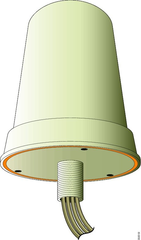
Cisco Aironet Dual-Band MIMO Wall-Mounted Omnidirectional Antenna (AIR-ANT2544V4M-R and AIR-ANT2544V4M-RS)
This document outlines the specifications for the Cisco Aironet 2.4-GHz/5-GHz Dual-Band MIMO Wall-Mounted Omnidirectional Antennas (AIR-ANT2544V4M-R and AIR-ANT2544V4M-RS) and provides instructions for mounting them. Both antennas operate in the 2.4 GHz and 5 GHz frequency ranges and are designed for indoor or outdoor use. The AIR-ANT2544V4M-RS antenna includes self-identifying circuitry.
The following information is provided in this document.
Technical Specifications
|
Brand |
CISCO |
 |
|
Model |
AIR-ANT2544V4M-RS |
|
|
Antenna type |
4-element MIMO omnidirectional |
|
|
Operating frequency range |
2400–2484 MHz |
|
|
5150–5850 MHz |
||
|
Nominal input impedance |
50 Ohms |
|
|
VSWR |
2:1 or less |
|
|
Peak gain |
2.4-GHz band: 4 dBi |
|
|
5-GHz band: 4 dBi |
||
|
Polarization |
Linear, vertical |
|
|
Azimuth plane(3 dB beamwidth) |
Ominidirectional |
|
|
Elevation plane(3 dB beamwidth) |
2.4-GHz band: 60° |
|
|
5-GHz band: 33° |
||
|
Length |
8.6 in (21.8 cm) |
|
|
Diameter |
6.3 in (16 cm) |
|
|
Weight |
Antenna: 1.48 lb. (671.5 g); |
|
|
Cable |
3-ft. (91.4 cm) plenum |
|
|
Connector |
RP-TNC |
|
|
Environment |
Indoor/outdoor |
|
|
Standard |
IEEE 802.11n |
|
|
Temperature range |
-22° F to 158° F(-30° C to 70° C) |
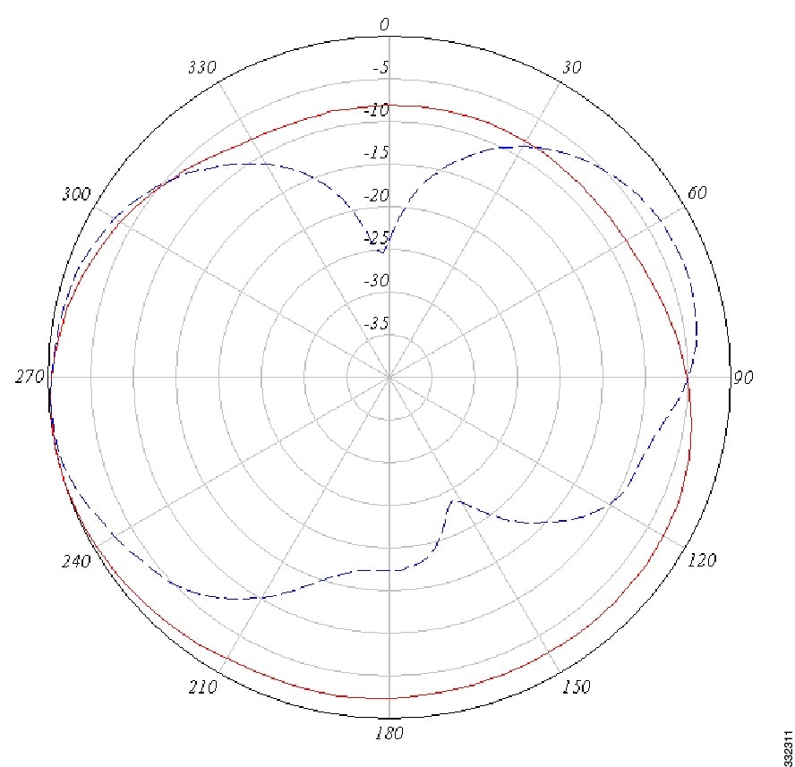
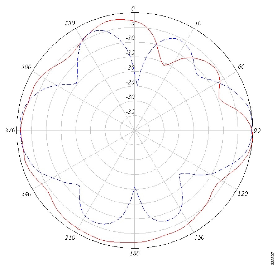
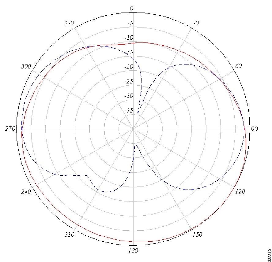
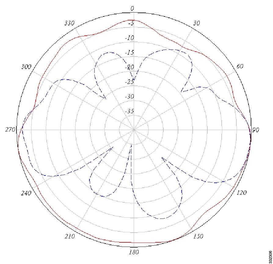
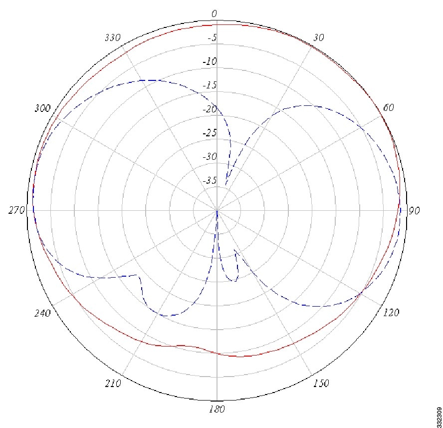
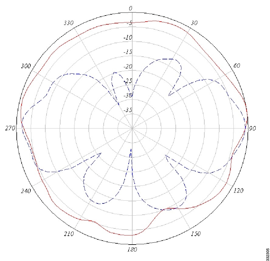
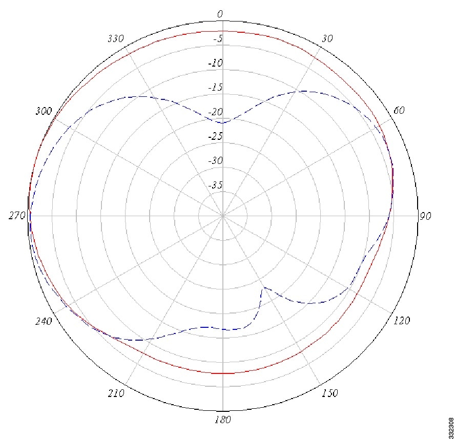
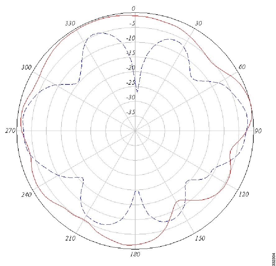
The figures below show the azimuth plane patterns (indicated by red lines) and elevation plane patterns (indicated by blue lines) for each element in the antenna.
| 2.4-GHz Antenna 1 Azimuth and Elevation Plane Patterns | 5-GHz Antenna 1 Azimuth and Elevation Plane Patterns |
|
|
|
| 2.4-GHz Antenna 2 Azimuth and Elevation Plane Patterns | 5-GHz Antenna 2 Azimuth and Elevation Plane Patterns |
|
|
|
| 2.4-GHz Antenna 3 Azimuth and Elevation Plane Patterns | 5-GHz Antenna 3 Azimuth and Elevation Plane Patterns |
|
|
|
| 2.4-GHz Antenna 4 Azimuth and Elevation Plane Patterns | 5-GHz Antenna 4 Azimuth and Elevation Plane Patterns |
|
|
|
System Requirements
This antenna is designed for indoor and outdoor use with any Cisco Aironet radio device with dual-band (2.4- and 5-GHz) RP-TNC connectors.
The Self Identifying Antenna model AIR-ANT2544V4M-RS= is supported only on Cisco Catalyst 9800 Series Wireless Controllers running an IOS-XE 17.4.1 release or a later release. This antenna model is not supported on Cisco AireOS Wireless Controllers.
Safety Precautions
 Warning |
Do not locate the antenna near overhead power lines or other electric light or power circuits, or where it can come into contact with such circuits. When installing the antenna, take extreme care not to come into contact with such circuits, as they may cause serious injury or death. For proper installation and grounding of the antenna, please refer to national and local codes (e.g. U.S.: NFPA 70, National Electrical Code, Article 810, Canada: Canadian Electrical Code, Section 54). Statement 280 |
For your safety, read and follow these safety precautions.
-
Before you install an antenna, contact your Cisco account representative to explain which mounting method to use for the size and type of antenna that you are about to install.
-
Find someone to help you—installing an antenna is often a two-person job.
-
Select your installation site with safety, as well as performance, in mind. Remember that electric power lines and phone lines look alike. For your safety, assume that any overhead line can kill you.
-
Contact your electric power company. Tell them your plans and ask them to come look at your proposed installation.
-
Plan your installation carefully and completely before you begin. Each person involved in an installation should be assigned to a specific task, and should know what to do and when to do it. One person should be in charge of the operation to issue instructions and watch for signs of trouble.
-
When installing your antenna, follow these guidelines:
-
Do not use a metal ladder.
-
Do not work on a wet or windy day.
-
Do dress properly—wear shoes with rubber soles and heels, rubber gloves, and a long-sleeved shirt or jacket.
-
-
If the assembly starts to drop, move away from it and let it fall. Because the antenna, mast, cable, and metal guy wires are all excellent conductors of electrical current, even the slightest touch of any of these parts to a power line completes an electrical path through the antenna and the installer.
-
If any part of the antenna system should come in contact with a power line, do not touch it or try to remove it yourself. Call your local power company to have it removed safely.
-
If an accident should occur with the power lines, call for qualified emergency help immediately.
Installation Notes
Antennas transmit and receive radio signals which are susceptible to RF obstructions and common sources of interference that can reduce throughput and range of the device to which they are connected. Follow these guidelines to ensure the best possible performance:
-
Install the antenna vertically and mount it with the cables pointing towards the ground.
-
Keep the antenna away from metal obstructions such as heating and air-conditioning ducts, large ceiling trusses, building superstructures, and major power cabling runs. If necessary, use a rigid conduit to lower the antenna away from these obstructions.
-
The density of the materials used in a building’s construction determines the number of walls the signal can pass through and still maintain adequate signal strength. Consider the following before choosing the location for your antenna:
-
Signals penetrate paper and vinyl walls with little change to signal strength.
-
Signals penetrate only one or two solid and pre-cast concrete walls without degrading signal strength.
-
Signals penetrate three or four concrete and wood block walls without degrading signal strength.
-
Signals penetrate five or six walls constructed of drywall or wood without degrading signal strength.
-
Signals will likely reflect off a thick metal wall and may not penetrate it at all.
-
Signals will likely reflect off a chain link fence or wire mesh spaced between 1 and 1 1/2 in. (2.5 and 3.8 cm). The fence acts as a harmonic reflector that blocks the signal.
-
-
Install the antenna away from microwave ovens and 2-GHz cordless phones. These products can cause signal interference because they operate in the same frequency range as the device to which your antenna is connected.
Choosing a Mounting Location
The antenna should be mounted clear of any obstructions to the sides of the radiating elements. Generally, the higher an antenna is above the floor, the better it performs. If possible, find a mounting place directly above your wireless device to ensure the lead-in cable can be as short as possible.
Installing the Antenna
You can install the antenna on any flat vertical surface, on a pole, or on a ceiling. All hardware for mounting the antenna on a wall or ceiling is provided. If you intend to install your antenna on another surface, you must provide the appropriate hardware.
Tools and Equipment Required
A mounting installation kit is included with the antenna and consists of the following hardware:
-
Mount interface bracket
-
Mount base
-
Wall bracket
-
One 1/4–20 x ½-in. cap screw
-
One 1/4–20 wing screw
-
Two #10 x ¾-in. screws
-
Two #10 x ½-in. screws
-
One screen mesh washer
-
One spherical washer
-
3/16 allen wrench
-
Rubber gasket
-
Jam nut
You may need the following tools and equipment, which are not provided.
-
A #2 Phillips screwdriver
-
A drill and drill bit
-
A pencil
-
Two hose clamps
Mounting on a Vertical Surface
Before you begin
Follow these steps to mount your antenna on a vertical surface.
Procedure
|
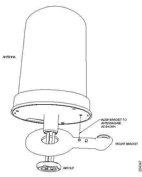
Step 1 |
Attach the antenna bracket to the antenna using the jam nut provided (Figure 1).
|
|
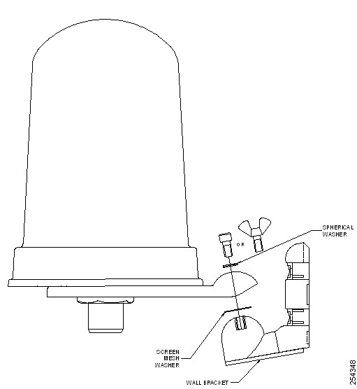
Step 2 |
With the screen mesh washer between the two brackets, attach the antenna bracket to the mounting bracket using the spherical washer and wing bolt provided (Figure 2).
|
|
Step 3 |
Determine the mounting location for the antenna. |
|
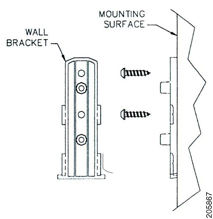
Step 4 |
Attach the wall bracket to the wall using the two screws provided (Figure 3).
|
|
Step 5 |
Slide the mounting bracket onto the wall bracket and secure it in place (optional) with the two screws provided (Figure 4). Once the antenna is secured on the wall, you can adjust the azimuth and elevation. 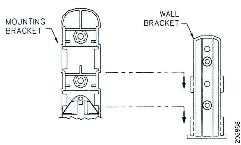 |
|
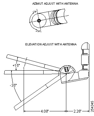
Step 6 |
To adjust the azimuth and elevation, loosen the bolt that attaches the antenna bracket to the mounting bracket (Figure 5). Azimuth can be adjusted ±90 degrees. Elevation can be adjusted +15 degrees and -35 degrees.
|
Mounting on a Ceiling
Before you begin
To mount the antenna on a ceiling, follow these steps:
Procedure
|
Step 1 |
Drill a hole in the ceiling approximately 1.25 in. in diameter. |
|
Step 2 |
Fit the rubber gasket onto the bottom of the antenna. |
|
Step 3 |
Insert the antenna shaft through the hole in the ceiling. |
|
Step 4 |
Thread the jam nut onto the antenna shaft and tighten. Figure 6 shows the ceiling mount process. 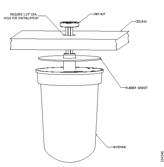 |
Mounting on a Mast
To mount the antenna on a mast, follow these steps:
Before you begin
The antenna can be mounted on a mast rather than on a wall using two 1/2 inch-wide hose clamps (not provided).
Procedure
|
Step 1 |
Follow Steps 1 and Step 2 from the “Mounting on a Vertical Surface” section. |
|
Step 2 |
Position the antenna, mounting bracket, and hose clamps on the mast. |
|
Step 3 |
Tighten the hose clamps until the antenna is secure on the mast. Once the antenna is secured on the mast, you can adjust the azimuth and elevation. |
|
Step 4 |
To adjust the azimuth and elevation, loosen the bolt that attaches the antenna bracket to the mounting bracket (Figure 5). Azimuth can be adjusted ±90 degrees. Elevation can be adjusted +15 degrees and -35 degrees. |
Connecting the Antenna to the Access Point
The AIR-ANT2544V4M-R has four cables with orange labels. The four cables can be connected to any of the four ports on the access point.
The AIR-ANT2544V4M-RS includes circuitry to enable self-identification of the antenna by the Cisco Catalyst 91xx Series Indoor Access Points. The antenna has three cables with orange labels and one cable with a purple label. The self identifying function is indicated by the purple label on this cable. Ensure that this antenna cable is connected to Port A on the AP, which is also designated by purple text around the RP-TNC connector. The AIR-ANT2544V4M-RS antenna has a built-in EEPROM that can be read by the AP to automatically configure the antenna type and gain in the wireless controller.
Suggested Cable
Cisco recommends a high-quality, low-loss cable for use with the antenna.
 Note |
Coaxial cable loses efficiency as the frequency increases, resulting in signal loss. The cable should be kept as short as possible because cable length also determines the amount of signal loss (the longer the run, the greater the loss). |
Communications, services, and additional information
-
To receive timely, relevant information from Cisco, sign up at Cisco Profile Manager.
-
To get the business impact you’re looking for with the technologies that matter, visit Cisco Services.
-
To submit a service request, visit Cisco Support.
-
To discover and browse secure, validated enterprise-class apps, products, solutions, and services, visit Cisco DevNet.
-
To obtain general networking, training, and certification titles, visit Cisco Press.
-
To find warranty information for a specific product or product family, access Cisco Warranty Finder.
Cisco Bug Search Tool
Cisco Bug Search Tool (BST) is a gateway to the Cisco bug-tracking system, which maintains a comprehensive list of defects and vulnerabilities in Cisco products and software. The BST provides you with detailed defect information about your products and software.
Documentation feedback
To provide feedback about Cisco technical documentation, use the feedback form available in the right pane of every online document.
Corporate address
Americas headquarters
Cisco Systems, Inc.
170 West Tasman Drive
San Jose, CA 95134-1706
USA
Tel: 408 526-4000; 800 553-NETS (6387)
Fax: 408 527-0883
 Feedback