Cisco Catalyst 9130 Series Access Point Deployment Guide
Available Languages
Bias-Free Language
The documentation set for this product strives to use bias-free language. For the purposes of this documentation set, bias-free is defined as language that does not imply discrimination based on age, disability, gender, racial identity, ethnic identity, sexual orientation, socioeconomic status, and intersectionality. Exceptions may be present in the documentation due to language that is hardcoded in the user interfaces of the product software, language used based on RFP documentation, or language that is used by a referenced third-party product. Learn more about how Cisco is using Inclusive Language.

Important Lifecycle Notice
Cisco announced the end-of-sale and end-of-life dates for this product. Read notice for further details and recommended new products.
This document is intended for trained and experienced technical personnel familiar with the existing Cisco® wireless enterprise networking product line and features.
Cisco Catalyst 9130 Series overview
Designed for next-generation mobility
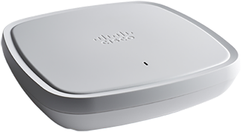
The Cisco Catalyst® 9130 Series Access Points, with high-performance Wi-Fi 6 capabilities and innovations in RF performance, security, and analytics, enable end-to-end digitization and help accelerate the rollout of business services by delivering beyond Wi-Fi.
● Resilient: Increased efficiency and cellular-like determinism with up to 4 times the capacity of 802.11ac access points, even in demanding environments
● Secure: Along with built-in security, and Software-Defined Access (SD-Access) support, these access points can deliver standards-compliant, enhanced security on open Wi-Fi
● Intelligent: With multi-RF support paramount for Internet of Things (IoT) devices and expanded ecosystem partnerships, the Cisco Catalyst 9100 portfolio provides unprecedented visibility from mobile devices on the Cisco network, along with enhanced Cisco DNA Assurance
The Cisco Catalyst 9100 Access Points come with built-in security in the form of secure boot, runtime defenses, image signing, integrity verification, and hardware authenticity. The 9100 portfolio, with Wi-Fi 6, provides reliable wireless to meet the needs of your branch and campus network deployments.
Cisco Catalyst 9130 Series key features
● Next-generation Wi-Fi 6 (802.11ax) access points with 4x4 Multiple-Input Multiple-Output (MIMO) and four spatial streams:
◦ 8x8:8 single or dual 4x4:4 on 5 GHz and downlink/uplink Orthogonal Frequency-Division Multiple Access (OFDMA)
◦ 4x4:4 on 2.4 GHz with multiuser MIMO (MU-MIMO) and downlink/uplink OFDMA
● Cisco DNA ready
● Cisco RF Application-Specific Integrated Circuit (ASIC) with next-generation Cisco CleanAir® and upgradable RF features
● Built-in Bluetooth Low Energy (BLE) radio (Bluetooth 5.0)
● Multigigabit Ethernet (1 Gbps, 2.5 and 5 Gbps)
● USB
● Supports up to 500 Wi-Fi devices
● IoT ready (BLE)
● Internal and external antenna options
● Operating temperature for 9130I: -32° to 122°F (0° to 50°C)
● Operating temperature for 9130E: -4° to 122°F (-20° to 50°C)
Cisco Catalyst 9130 Series key capabilities
● OFDMA and MU-MIMO: Deliver more predictable performance for advanced applications and IoT
● Superior security with RF signature capture, rogue detection, and device classification
● Container support: Multilingual access point with Docker support to host IoT applications
● Multigigabit support: Seamlessly offload network traffic without any bottlenecks and allow for higher throughputs with minimum cost
● Integrated Bluetooth 5.0: Multi-RF technologies to enable IoT use cases
● Internal and external antenna support: Flexible deployment options for various campus types
● Multiple-input power options, ranging from 802.3af (limited) to 802.3bt
In addition, the Cisco Catalyst 9100 Access Points support SD-Access, Cisco’s leading enterprise architecture.
Choosing the right access point, Models 9130I and 9130E
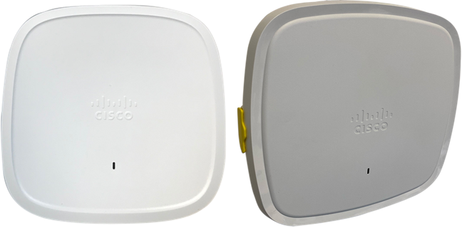
Cisco Catalyst 9130I (with internal antennas) and 9130E (requires an external antenna) access points
Use cases for 9130I model
● Aesthetics (carpeted areas)
● No additional antenna costs
● Fewer items to install
● Sometimes better for high ceilings
Use cases for 9130E model
● Industrial applications requiring operation in higher temperatures
● Need for external or directional antennas (inside/outside use)
● Longer ranges or need to focus energy
● Dual 5-GHz (covering different cell areas) directional or omnidirectional
● Use of legacy single-band antennas or different 2.4-GHz and 5-GHz cells
Cisco Catalyst 9130 Series new mechanical design
The Cisco Catalyst 9100 Access Points are built from the ground up, with a new aerodynamic look and smooth finish, integrating RF excellence and next-generation technologies to provide a best-in-class wireless experience without compromise. While incorporating several high-performance features, the hardware has been redesigned to deliver greater efficiencies in a more compact form factor to make visually appealing Wi-Fi deployments commonplace.
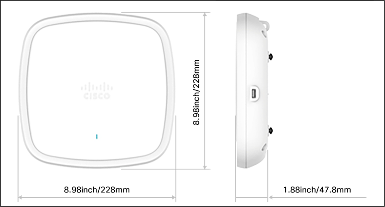
Mechanicals: 9130I model
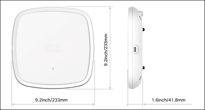
Mechanicals: 9130E model
Note: The 9130 Series is approximately 13 percent lighter and has 25 percent lower volume than the Cisco Aironet® 2800 Series, yet is easy to deploy using the same AIR-BRACKET-1 and AIR-BRACKET-2 mounting hardware.
Many different installation options are available, depending upon the requirements of the customer. Brackets are available from Cisco as well as third-party companies. During the ordering process, the customer may choose one of two brackets (but not both). Each bracket is a zero-dollar ($0) option at the time of configuration. If the customer does not choose a bracket, the default is AIR-AP-BRACKET-1, which is the most popular for ceiling installations. The other choice is a universal bracket that carries part number AIR-AP-BRACKET-2.
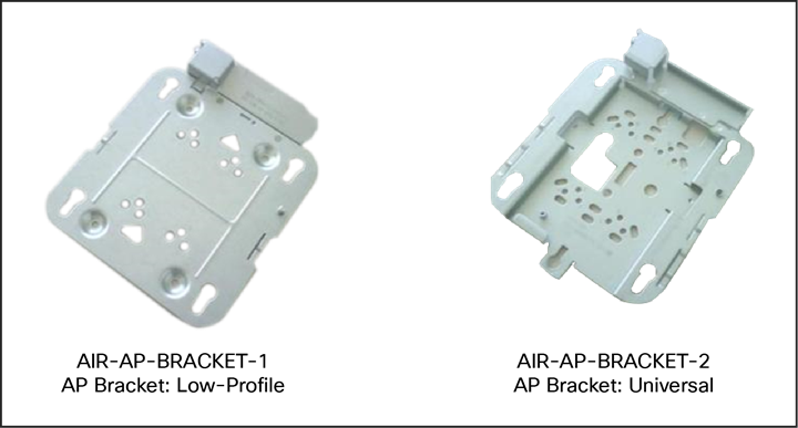
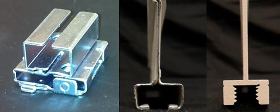
Two different types of mounting brackets
If the AP will be mounted directly to a ceiling on the gridwork, the AIR-AP-BRACKET-1 bracket mounts flush and has the lowest profile. However, if the AP will be mounted to an electrical box or other wiring fixture, inside a National Electrical Manufactuers Association (NEMA) enclosure, or on a wall, AIR-AP-BRACKET-2 is a better choice. The extra space in this bracket allows for wiring, and the extra holes line up with many popular electrical boxes. When the bracket is mounted to the ceiling gridwork, some ceiling tiles are recessed. For this reason, two different styles of ceiling clips, recessed and flush rails, are available. See the figure below.
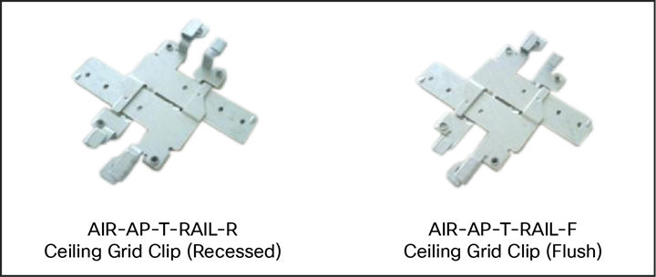
Clips for attaching to ceiling gridwork
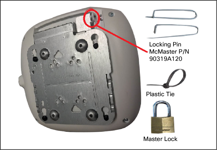
Securing the AP
If the AP needs to be secured in the bracket, it can be done as shown in the figure above.
When mounting APs to ceiling channel rails such as the ones shown in the figure below, an optional channel adapter is used: AIR-CHNL-ADAPTER. It comes in a two-pack and attaches to the ceiling grid clip. Refer to Figures 8 and 9.
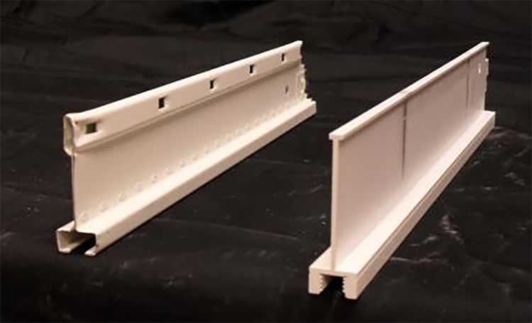
Example of channel rails
AIR-CHNL-ADAPTER (left) slides onto the rails
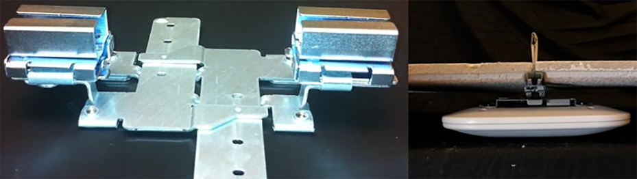
AIR-CHNL-ADAPTER mounted to rail clip (left) and finished installation (right)
Wall-mounting the AP
When wall mounting is desired, the installer should understand that walls can be physical obstacles to the wireless signal; therefore, the ability to maintain 360-degree coverage may be compromised. If the wall is an outside wall and/or the goal is to send the signal in a 180-degree pattern instead, a directional antenna, often referred to as a “patch” antenna, may be a better choice, assuming that the external antenna model is used.
Avoid wall-mounting APs with internal antennas unless you use an optional right-angle mount (available from third-party companies), as the internal antenna model was designed to mount to a ceiling to provide 360-degree coverage.
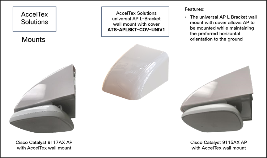
AccelTex wall-mounting solutions for 9115AX, 9117AX, 9120AX, and 9130 Series access points
The following third-party companies are recommended for different types of mounting solutions.
If wall-mounted in a non-ceiling orientation, the signal may penetrate the floor above and below, causing unintended coverage that could result in additional needless roaming access when a mobility client (for example, a user with a Wi-Fi phone) walks by on an adjacent floor.
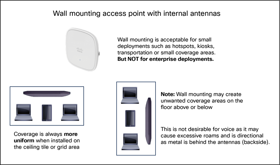
Caveats when wall mounting the 9130 Series
Changing the color of an AP
If there is a desire to change the color of an AP, rather than painting it, which would void the warranty, consider using colored vinyl tape or a colored plastic cover from Oberon.
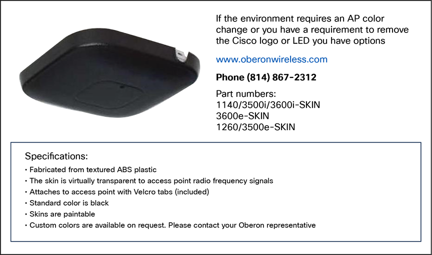
Oberon third-party option for changing the AP color, adding a custom logo, or hiding the LED

Vinyl “skins” from AccelTex
Another third-party option is a vinyl “skin” such as the ones shown above.
Above the ceiling tiles
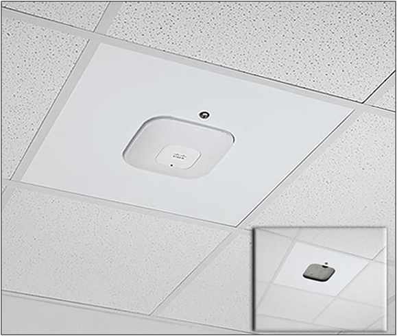
The Cisco Catalyst 9130I and 9130E are rated for installation in the plenum area (UL-2043). Many customers prefer to locate the AP so that nothing is visible on the ceiling, for aesthetic reasons. If so, you may install the AP above a drop ceiling. This also may be preferred in high-theft areas such as classrooms or in areas where policy dictates that nothing can be visible on the ceiling.
When this is a hard requirement, optional T-bar hanger accessories from third-party companies such as Erico and Cooper can be used. The Erico Caddy 512a, the Cooper B-Line BA50a, or similar T-bar grid can be used.
For more information, see:
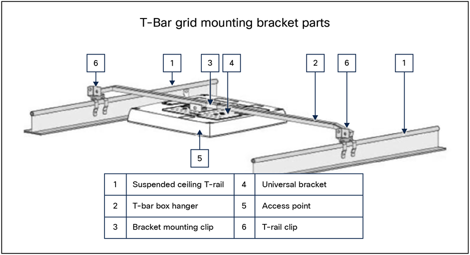
Example of how to hang an AP above the ceiling tiles
Note: Installing APs above the ceiling tiles should be done only when mounting below the ceiling is not an option. The tiles must not be conductive; such installations can degrade advanced RF features such as voice and location, so verify coverage and performance. Always try to mount the AP as close to the inside middle of the tile as possible, and avoid areas with obstructions.
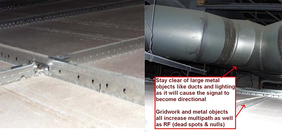
Installing the AP above ceiling tiles: Pick an area clear of obstructions, and avoid ceiling clutter
Areas with high vibration
If the access point is installed using a “side arm” type mount or in a mounting location where there is a likelihood of high vibration, it is recommended that a padlock or metal pin be used to prevent the AP from vibrating loose from the bracket.
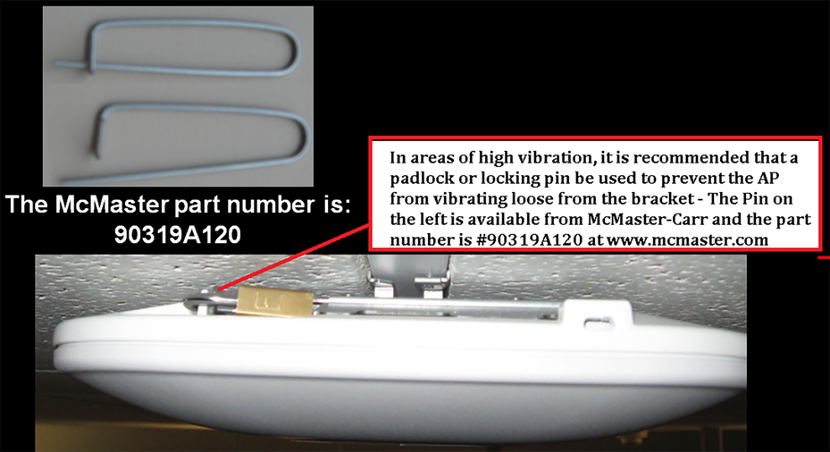
A metal pin or padlock will not deteriorate over time, and so is better than a plastic tie
The 9130 Series offers flexible power options even with limited 802.3af power.
Table 1. 9130 Series power draw
| Catalyst 9130AXI |
||||||
| PoE Power Consumption |
2.4-GHz radio |
5-GHz radio |
Link speed |
USB |
LLDP |
|
| 802.3at (PoE+) |
4x4 |
8x8 |
5G |
N |
25.5W |
|
| 802.3at (PoE+) |
4x4 |
4x4 |
5G |
N |
25.5W |
|
| 802.3bt (UPoE) |
4x4 |
8x8 |
5G |
Y [4.5W] |
30.5W |
|
| Catalsyt 9130AXE |
||||||
| PoE Power Consumption |
2.4-GHz radio |
5-GHz radio |
Link speed |
USB |
LLDP |
|
| 802.3at (PoE+) |
4x4 |
4x4 |
5G |
N |
25.5W |
|
| 802.3bt (UPoE) |
4x4 |
8x8 |
5G |
Y [4.5W] |
30.5W |
|
| Catalyst 9130AXI / 9130AXE |
||||||
| PoE Power Consumption |
2.4-GHz radio |
5-GHz radio |
Link speed |
USB |
LLDP |
|
| 802.3af |
PoE |
1x1 |
1x1 |
1G |
N |
13.4W |
Note: The Ethernet cable recommended is CAT-6 with a maximum distance of 328 feet (100 meters). Power required at the Power Source Equipment (PSE) will depend on the cable length and other environmental issues.
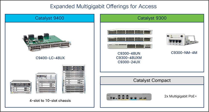
Cisco Multigigabit products
Cisco has a line of Multigigabit products that can easily power these access points.
The RF ASIC integrated into the Cisco Catalyst 9130 Series improves the RF spectrum and performance of the access points’ client-serving radios.
Next-generation Wi-Fi 6 access points such as the Cisco Catalyst 9130 Series now contain a new radio based on custom-designed Cisco silicon referred to as an ASIC (application-specific integrated circuit). This analytics radio enhances the performance of the access points’ client-serving radios, as all this deep RF analysis is done on the RF ASIC.
The function of the Cisco RF ASIC (actually two ASIC chips) is to analyze a frequency or range of frequencies of interest, converting the received RF signal into quadrature signals known as I/Q data. This I/Q data is then passed on to a second ASIC that is a dedicated baseband processor for a deep RF analysis, such as determining granular changes in the phase and amplitude as well as the modulation characteristics of the inspected signal.
The I/Q data is evaluated by the Spectrum Analysis Engine (SAgE), which is custom designed to identify sources of non-Wi-Fi interference, at the highest resolution, in the most simple and effective way.
Think of the RF ASIC as a unique piece of hardware that not only contains CleanAir and SAgE but is also much more advanced and has the capability to support advanced features in the future with software upgrades.
The initial capabilities of the RF ASIC include all the features of CleanAir and SAgE as well as the ability to sense Dynamic Frequency Selection (DFS) events to augment the serving radio’s analysis of DFS. This greatly improves spectrum analysis and provides an always-on “second opinion” of the radio spectrum. This is referred to as dual DFS. In addition, the RF ASIC also plays a key role in Cisco’s RRM (Radio Resource Management) by providing off-channel analysis.
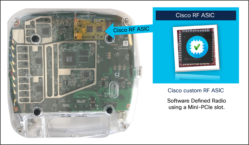
Cisco Catalyst 9130I with the Cisco RF ASIC chip
Cisco Catalyst 9130I internal antenna system
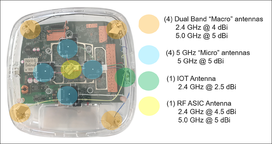
9130I internal antenna system
The 9130I has one of the most advanced antenna systems available on an access point.
The main serving radios default to this configuration:
● A dedicated 5-GHz radio is tied to the dual-band client-serving antennas at 4 dBi.
● When in 5-GHz 8x8 mode, the four dual-band antennas and the four micro antennas are fully used, while the 2.4-GHz radio is also active in 4x4 mode using the dual-band antennas.
● Unlike in previous models, the (eXclusive OR) known as XOR radio is no longer tied to the 2.4-GHz radio (which is active regardless of XoR state).
● In dual 5-GHz mode, the 8x8 5-GHz radio changes state from 8x8 to 4x4, enabling a secondary 5-GHz radio to run independently on the micro antennas for a true dual micro/macro cell approach.
In addition to the serving radio antennas, there are two other antennas:
● BLE (IoT) antenna with a gain of 2.5 dBi
● RF ASIC antenna with a gain of 2.4 GHz at 4.5 dBi and 5 GHz at 5 dBi
The RF ASIC antenna is connected to a dedicated software-defined radio for spectrum analysis and other advanced RF features. The RF ASIC antenna is of the same design as the serving radio antennas to provide a similar view of the network as the serving radios.
The newer antenna design on the Cisco Catalyst 9130 Series is an improvement over the older Aironet 4800i, as the micro-cell antenna coverage has been improved to allow for a new concept called a “meso” cell. A meso cell is a hybrid between a macro and a micro cell. This hardware innovation may lead to improved coverage in the micro cell with newer software releases.
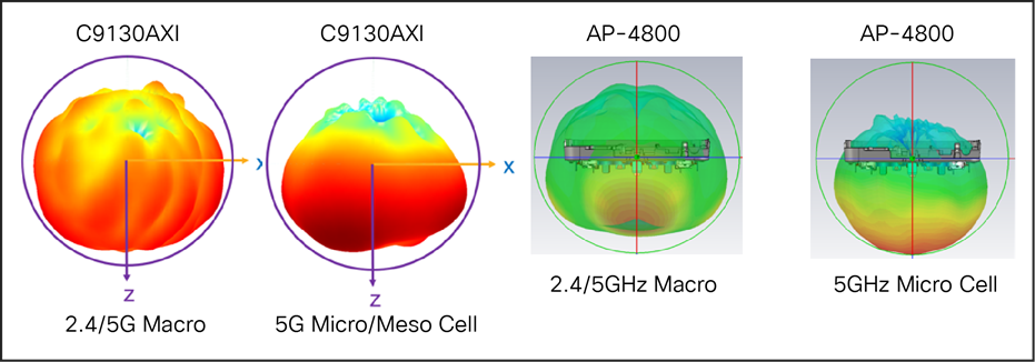
Comparison of antenna coverage in the Cisco Catalyst 9130I and Aironet 4800 Series
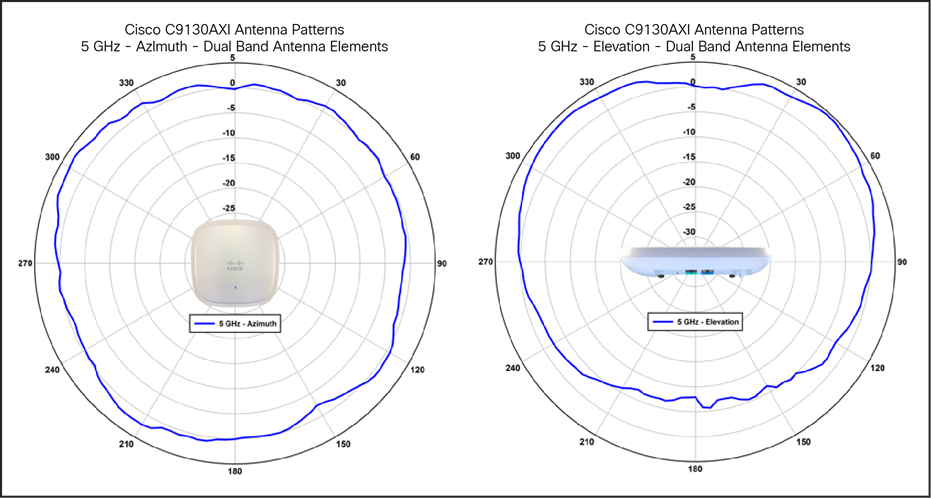
Cisco Catalyst 9130I antenna patterns, dual-band 5 GHz
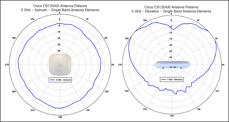
Cisco Catalyst 9130I antenna patterns, single-band 5 GHz
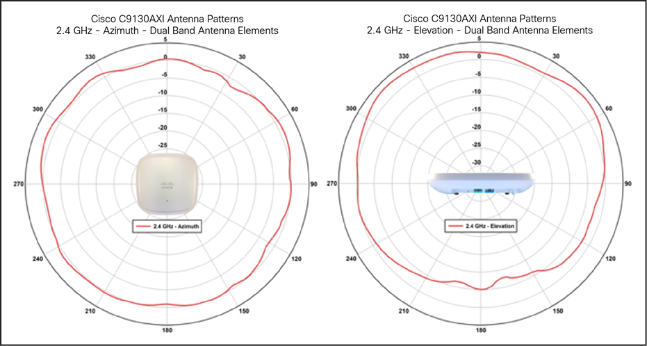
Cisco Catalyst 9130I antenna patterns, dual-band 2.4 GHz
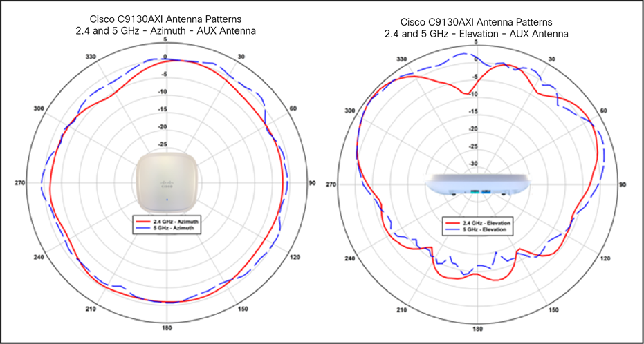
Cisco Catalyst 9130I antenna patterns, RF ASIC (AUX dual band)
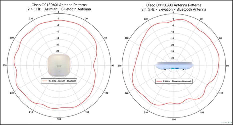
Cisco Catalyst 9130I antenna patterns, BLE and IoT
Cisco Catalyst 9130E (external antenna model)
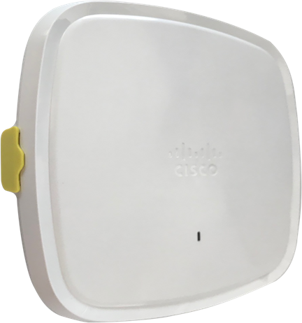
9130E showing antenna connector
Note: The 9130E requires the use of an external antenna system. The yellow cover (on the left) must be removed and a suitable antenna system installed via the 8-port DART “smart” connector, which is exposed once the yellow cover is removed. Do not operate the unit without a suitable antenna.
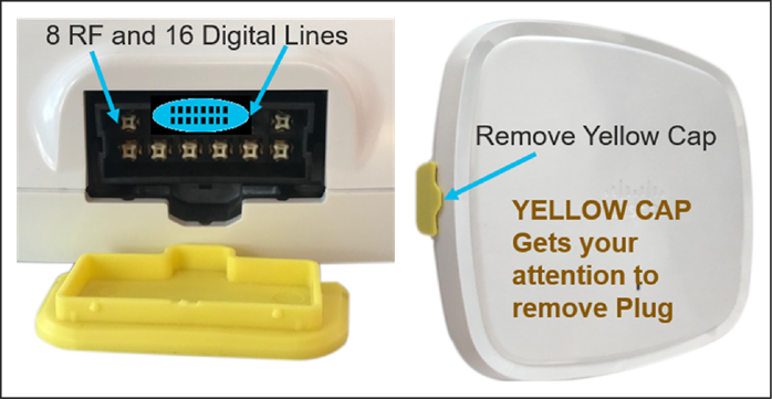
9130E antenna connector details
The 9130E uses a smart antenna connector (above) and does not contain internal antennas or RP-TNC connectors. If older antennas with RP-TNC connectors or “N”-style connectors are desired, adapter cables are available that can be used.
Understanding the smart antenna connector (DART-8)
In the 9130E, with modes such as dual 5G, 4x4 + 4x4 + (4x4 in 2.4 GHz), the older RP-TNC single RF connector was no longer practical. Cisco developed the DART-8 to simplify installations and to create a single insertion cable to go along with a new line of Self-Identifying Antennas (SIA) containing circuitry to automate provisioning and detection, eliminating the need for special professionally installed models (with product numbers ending in “-P”) going forward. Customers who have existing antennas can connect them to the 9130E via a DART-8 (smart adapter cable).
The Cisco Catalyst 9130E is designed for use with SIAs that are terminated with a smart antenna connector (DART-8). The use of a DART adapter cable will put the AP into legacy antenna mode. Depending upon the adapter being used, antennas up to 6 dBi (with RP-TNC) or up to 13 dBi (with “N”-style connectors) may be used.
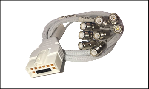
Cisco AIR-CAB-002-D8-R= connector for conventional antennas up to 6 dBi with RP-TNC connectors
Cisco AIR-CAB-003-D8-N= for conventional antennas up to 13 dBi with “N”-style connectors
When AIR-CAB-002-D8-N= is used, antennas previously designed for professional installation (model numbers ending in “-P”) may be used with the 9130E, so there is no “-P” model for the 9130E.
Note: The 4-port DART adapter used with the Cisco Catalyst 9120AXE, Cisco part number AIR-CAB-002-DART-R=, is not compatible with the newer Cisco Catalyst 9130E Access Point.
Understanding the Cisco Catalyst 9130 Series tri-radio support
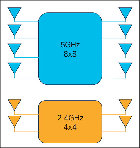
Default mode on the 9130 Series
The Cisco Catalyst 9130 Series can run 5 GHz in 8x8 or dual 5-GHz 4x4 mode.
The default mode on the 9130 Series is 5-GHz 8x8 and 2.4-GHz 4x4 mode. This default mode provides the highest throughput per single radio, with performance gains mainly in MU-MIMO client environments. This mode provides a better data rate but less range, with more receivers hearing the client for better Maximal-Ratio Combining (MRC).
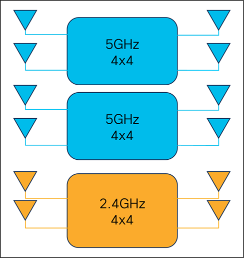
Dual 5-GHz 4x4 mode
There are instances when it becomes beneficial to change the operation of the 5-GHz radio from 8x8 into two independent 5-GHz 4x4 radios. The benefit with dual 5-GHz 4x4 radios is that it allows for macro-micro cell operation, which is very useful in high-density environments. It also permits more clients for greater performance when there are fewer Wi-Fi 6-capable clients or when the need arises to create two different 5-GHz Wi-Fi coverage cells or change operational modes such as monitoring.
Table 2. Example of Cisco Catalyst 9130 Series operational modes and criteria
| 5 GHz Radio Role |
Drivers |
|
| Radio 1 |
Radio 2 |
|
| 8x8 Client serving |
None |
Preferred Operation in 160MHz or 80+80MHz Higher MU-MIMO Stations Lower Channel reuse requirement Required Higher Number of Spatial Streams (SS) |
| 4x4 Client serving |
4x4 Client serving |
High Client Density and Capacity requirements Directional Antenna Units (Coverage Slicing) Operation as 80MHz or below |
| 4x4 Client serving |
Monitor |
Lower MU-MIMO Stations Low density, better channel reuse Monitoring Application Requires 4x4 RX |
Configuring the Cisco Catalyst 9130 Series tri-radio
On initialization (by default) the 9130 Series will be in 2.4-GHz 4x4 and 1x 5-GHz 8x8 mode. Note that at the radio interface configuration level, dual radio mode is Auto (disabled). “Auto” indicates that the radio may be assigned by Flexible Radio Assignment (FRA), and “disabled” indicates that it has either been assigned as an 8x8 mode or has not yet been evaluated by FRA. If FRA assigned dual 5-GHz mode, “disabled” will become “enabled.” Either way, “Auto” indicates that the radio is in FRA mode and has not been overridden manually. All eight antennas will be assigned to this single interface.
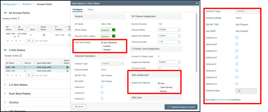
Also note that in the interface list, slots 1 and 2 for the same AP are both listed; however, slot 2 is grayed out because it is already active as part of slot 1’s 8x8 mode and thus is not addressable as slot 2. To enable dual-band mode, select Dual Radio Mode –> Enabled. This will manually split the 8x8 into two functioning, independent 4x4 radios.
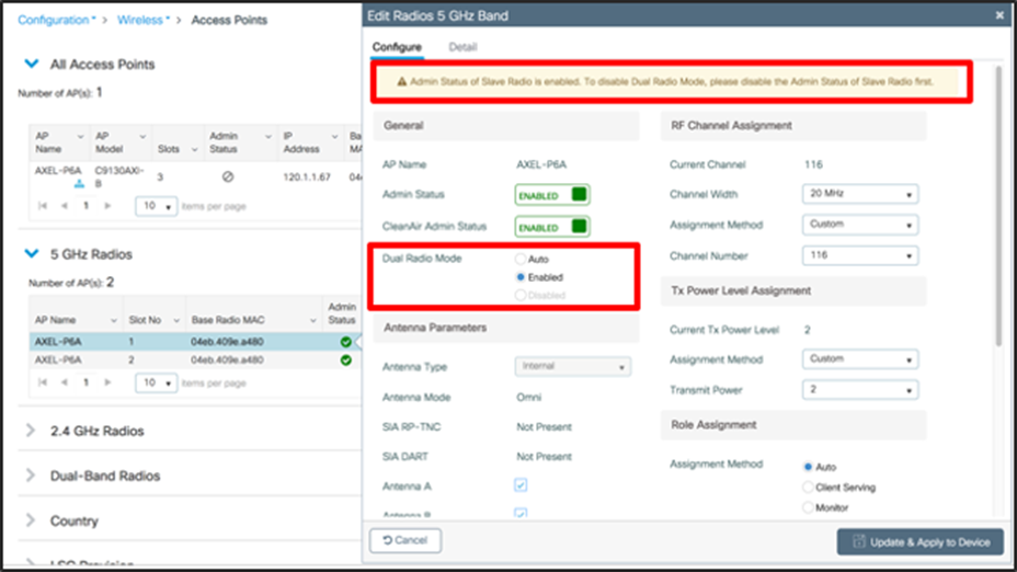
The radio in slot 1 switches to using only four antennas. The slot 2 radio becomes active and also has four antenna chains. Each 4x4 radio is now an independent interface and can be assigned a different channel and will serve two different groups of users.
Note: Once the Admin status of the secondary radio is enabled, to disable dual radio mode, you must first disable the Admin status of the secondary radio. Otherwise, this warning will appear.

This means that if you manually assign dual 5 GHz and then want to manually switch back to 8x8 single-radio mode, you will first need to disable the second 5-GHz interface so it is free to be added back to the primary radio on slot 1.
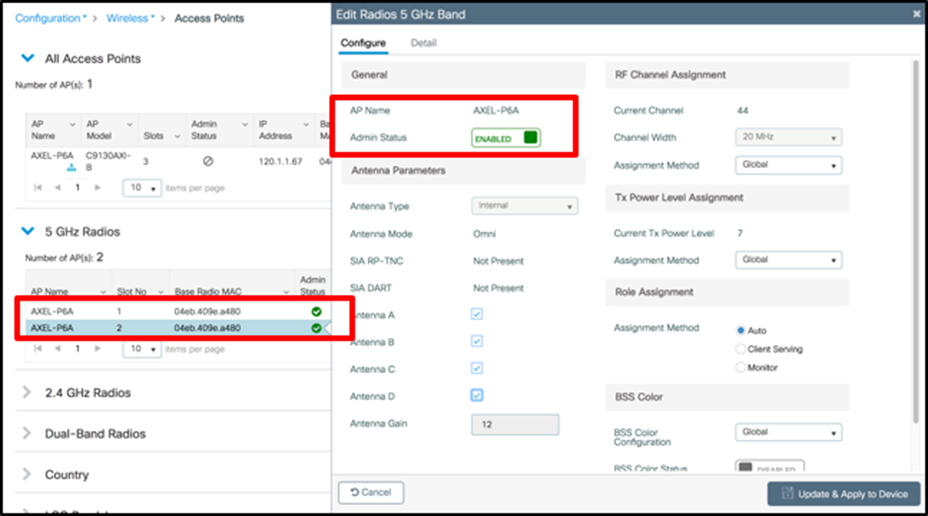
Slot 1 and slot 2 are enabled, and slot 2 has independent configurations as well as four of the eight available antennas assigned to it.
Configuring for FRA is the same for the tri-radio as it is for other Cisco FRA-capable APs. The FRA role must be selected. “Auto” leaves it up to FRA, and “Client Serving” means it will serve clients and beacon as an active interface. “Monitor” means that it will simply scan all of the channels in the 5-GHz band.
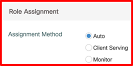
Role selection is available for both interfaces or just one, depending on the configuration of dual radio mode. When dual radio mode is enabled, both interfaces are assignable by FRA and both have independent role selection. In Auto mode, the available choices for FRA will be between Client Serving and Monitor and will be assigned by FRA based on the number of active 5-GHz interfaces that are available and the availability of noninterfering channels for assignment to the first and second 5-GHz interface.
It is possible that, under FRA’s control, no 5-GHz interfaces will be assigned to Client Serving. This would occur if RRM’s Dynamic Channel Assignment (DCA) doesn’t have an available noninterfering channel to assign, and would generally be because of channel exhaustion (too many 5-GHz interfaces too close together), based on over-the-air measurements. To free more channels, check on the channel bandwidth you are assigning. An 80-MHz channel bandwidth will consume four channels per interface and, in dual 5-GHz mode, will require eight channels for a single AP. Reconfiguring the channel to 40 MHz will free four channels per dual 5-GHz AP and allow a lot more interfaces to be active without interference.
Understanding self-identifying antennas
Self-identifying antennas
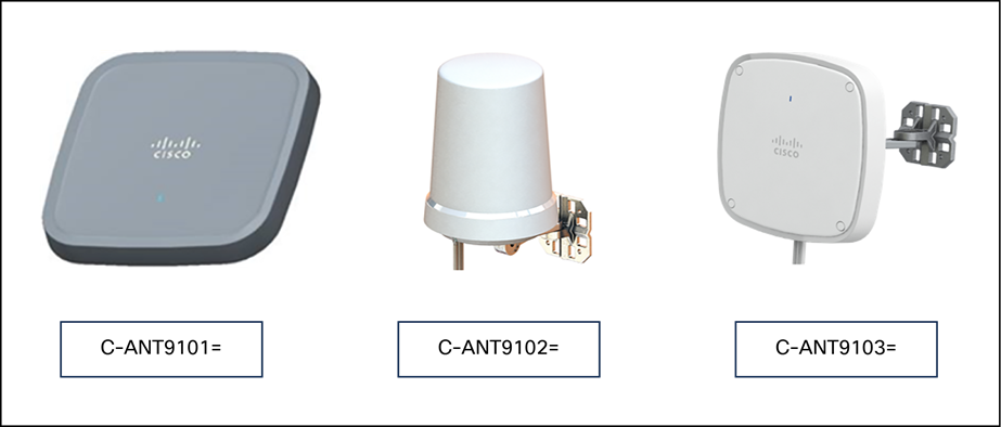
With the release of the 9130E, we are introducing three new antennas with the smart antenna connector. These antennas sport a new industrial design that is designed to complement the access point.
Note: These three antennas fully support 5 GHz in 8x8 mode and 2.4 GHz in 4x4 mode as well as BLE/IoT and RF ASIC functionality, but they do not support dual 5 GHz due to the antennas’ smaller sizes. Higher-gain antennas with additional features and modes such as dual 5 GHz are planned.
C-ANT9101= Ceiling mount omnidirectional, similar to AIR-ANT2524V4C-R=
C-ANT9102= Wall/pole mount omnidirectional, similar to AIR-ANT2544V4M-R=
C-ANT9103= Wall/pole mount patch, similar to AIR-ANT2566D4M-R=
The above antennas have a single insertion cable, and each antenna contains SIA circuitry to automate provisioning and detection. In addition, each antenna contains an indicator light (LED) that mimics the light on the access point, allowing the antenna to have an “active” status.
For installations where a longer cable length between the C9130AXE and one of the above antennas is needed, a 3-foot extension cable is available (AIR-CAB003-D8-D8=). Note that use of the extension cable will increase the RF signal loss in both Tx and Rx directions.
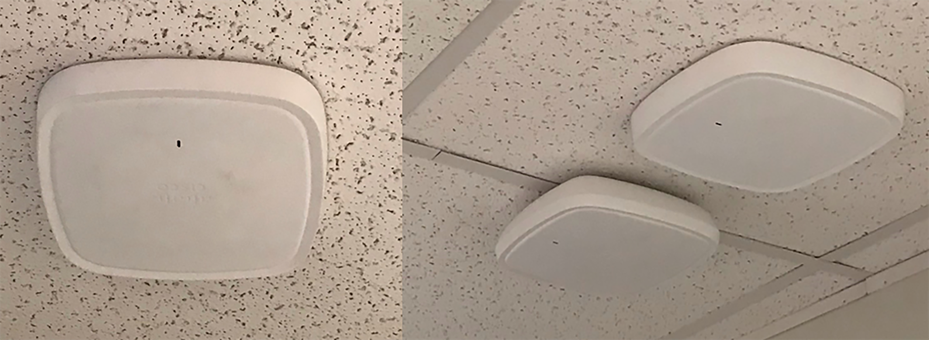
C-ANT9101= Ceiling-mount omnidirectional antenna
The Cisco C-ANT9101 ceiling-mount omnidirectional antenna allows for installations in the center of the tile and has a lower profile than the access point mounted on the ceiling rail (pictured above next to the antenna on the right). This allows the AP to be placed above the ceiling tiles.
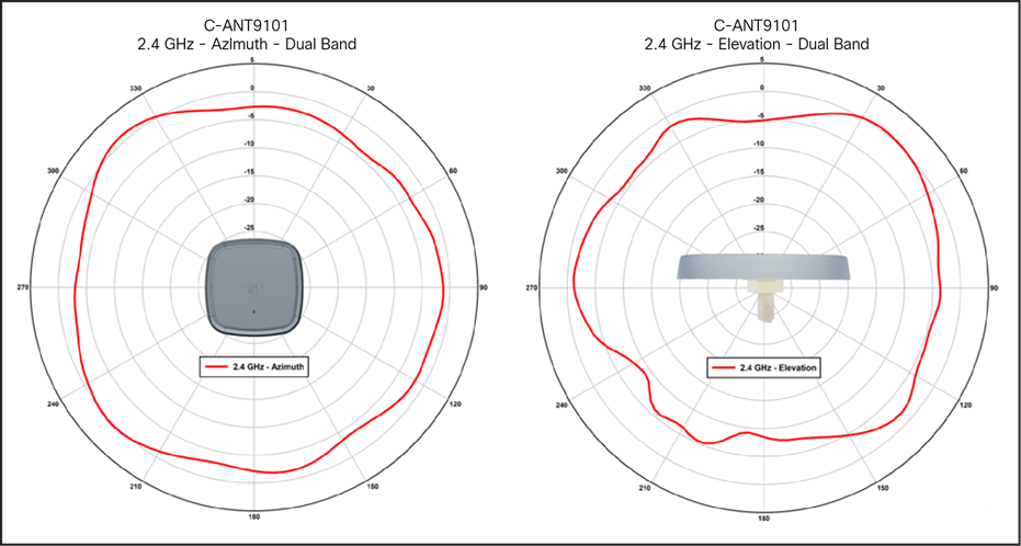
C-ANT9101 antenna patterns, 2.4-GHz dual band
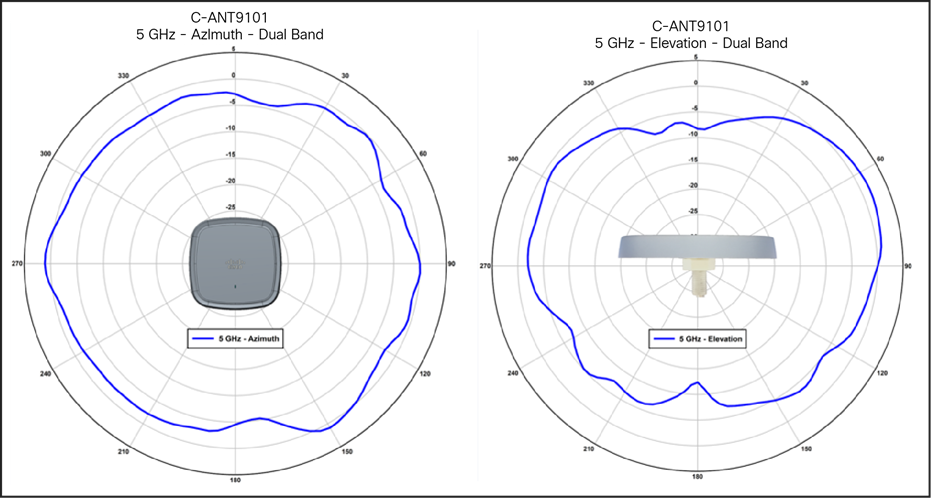
C-ANT9101 antenna patterns, 5-GHz dual band
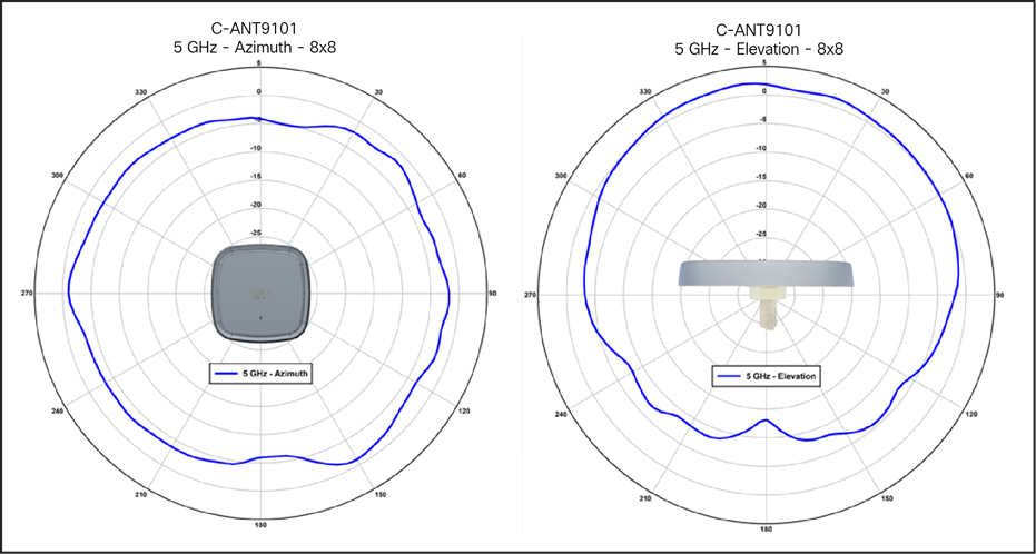
C-ANT9101 antenna patterns, 5-GHz single band
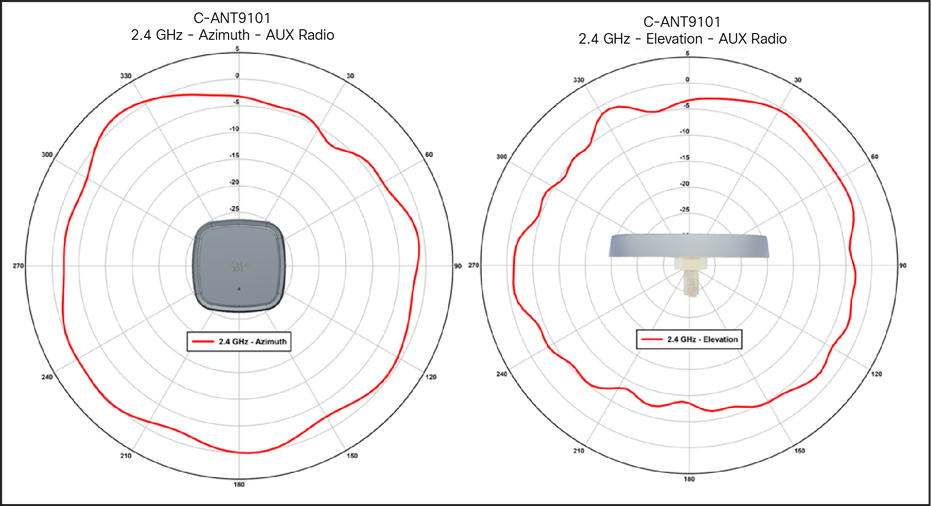
C-ANT9101 antenna patterns, 2.4-GHz RF ASIC / AUX
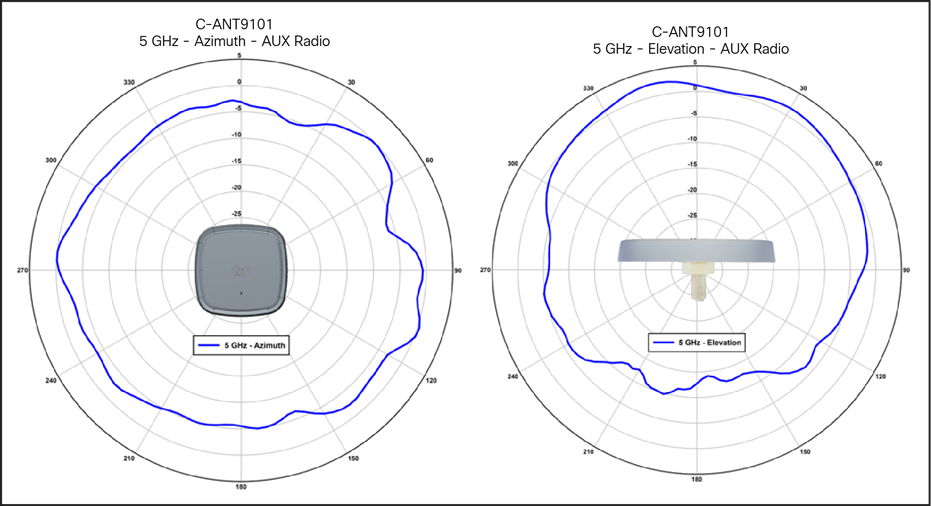
C-ANT9101 antenna patterns, 5-GHz RF ASIC / AUX
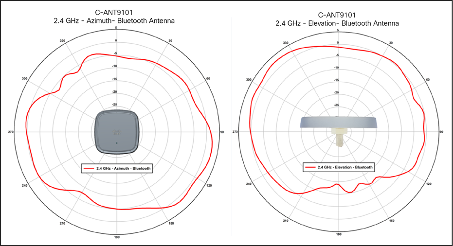
C-ANT9101 antenna patterns, 2.4-GHz BLE/IoT
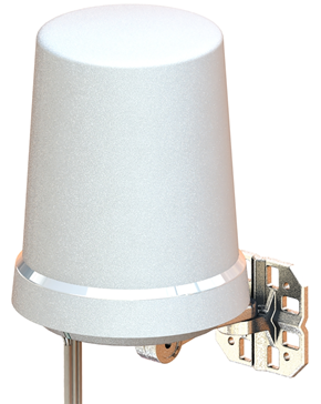
C-ANT9102= wall/pole-mount omnidirectional antenna
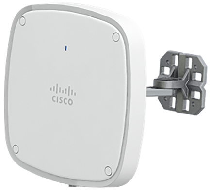
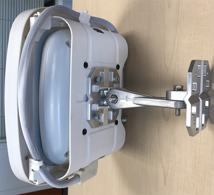
The Cisco C-ANT9102 wall/pole-mount omnidirectional antenna allows for installations where pole and wall mounting are desired, such as manufacturing and retail venues. This is a self-identifying antenna with active LED that mimics the LED on the access point. The ray dome material is Lexan EXL 9330 and is terminated with a smart 8-port DART antenna connector.
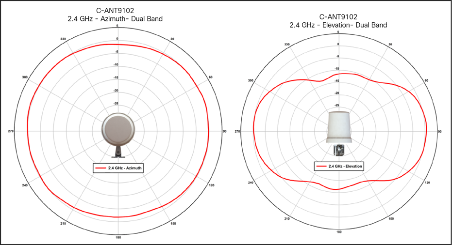
C-ANT9102 antenna patterns, 2.4-GHz dual band
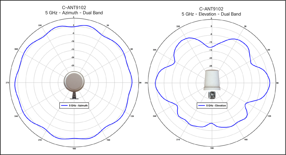
C-ANT9102 antenna patterns, 5-GHz dual band
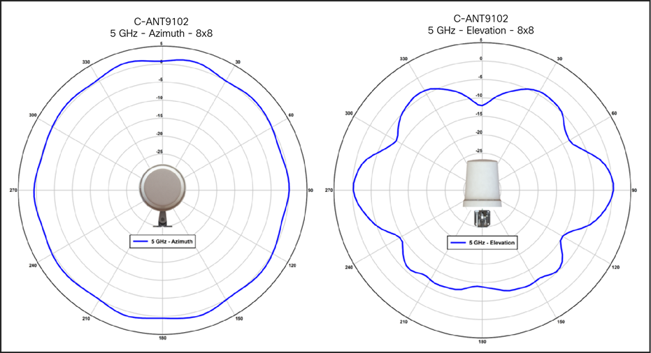
C-ANT9102 antenna patterns, 5-GHz single band
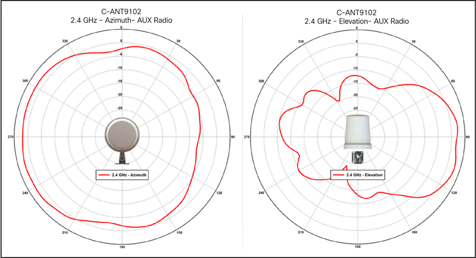
C-ANT9102 antenna patterns, 2.4-GHz RF ASIC / AUX
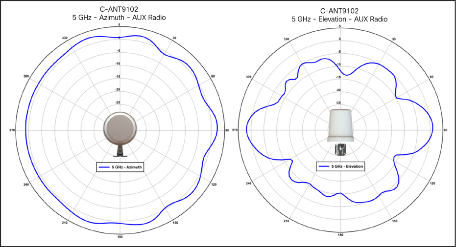
C-ANT9102 antenna patterns, 5-GHz RF ASIC / AUX
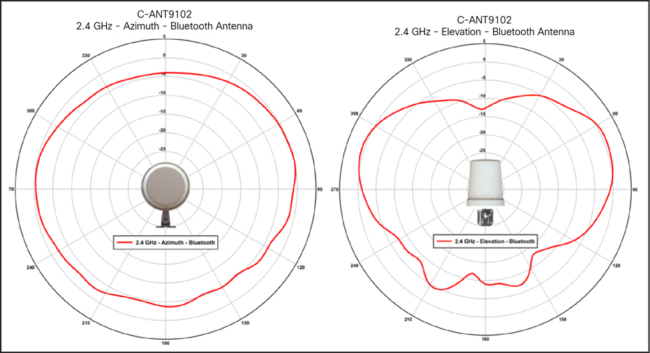
C-ANT9102 antenna patterns, 2.4-GHz BLE/IoT
C-ANT9103= 6 dBi directional wall/pole-mount antenna
The Cisco C-ANT9103 wall/pole-mount directional antenna allows for installations where pole and wall mounting are desired, such as manufacturing and retail venues. This is a self-identifying antenna with an active LED that mimics the LED on the access point.
C-ANT9103= with optional AP bracket AIR-AP-BRACKET-9=
An optional bracket allows the AP to be mounted behind the antenna.
This smart antenna with LED has a right-angle DART connector to allow an elegant “hidden” AP look.
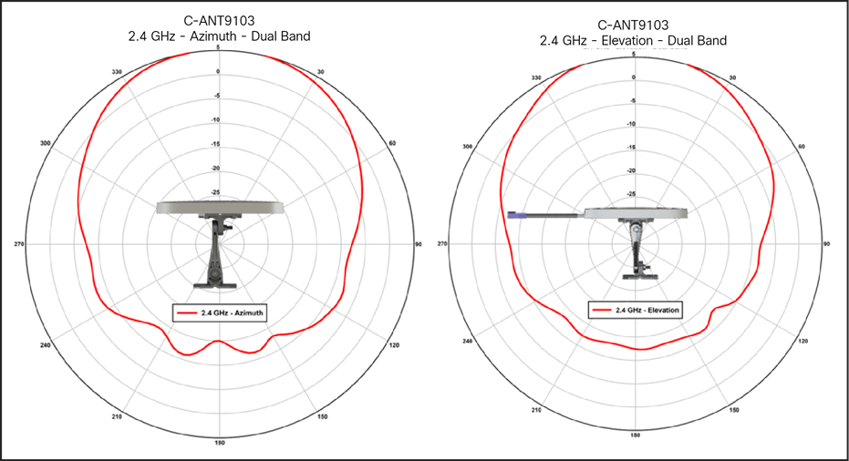
C-ANT9103 antenna patterns, 2.4-GHz dual band
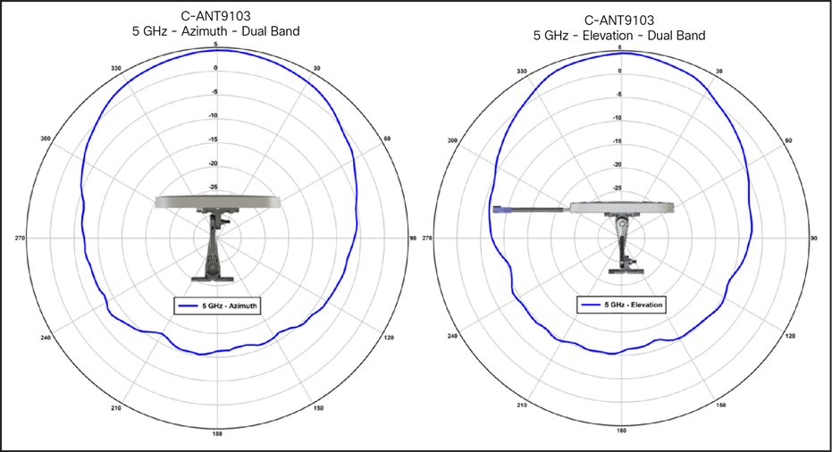
C-ANT9103 antenna patterns, 5-GHz dual band
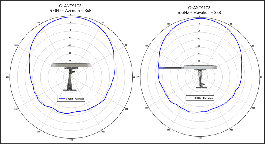
C-ANT9103 antenna patterns, 5-GHz single band
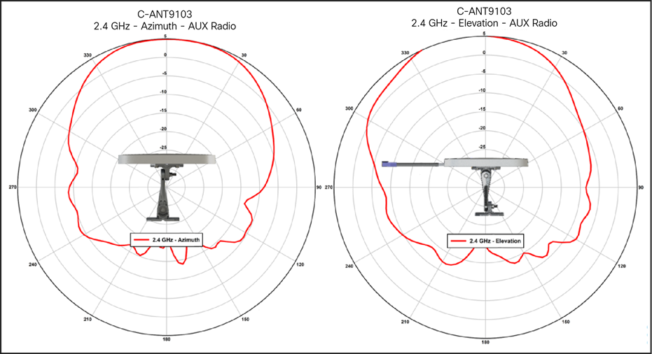
C-ANT9103 antenna patterns, 2.4-GHz RF ASIC/AUX
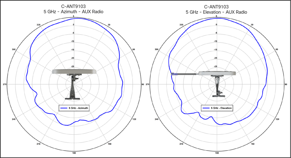
C-ANT9103 antenna patterns, 5-GHz RF ASIC/AUX
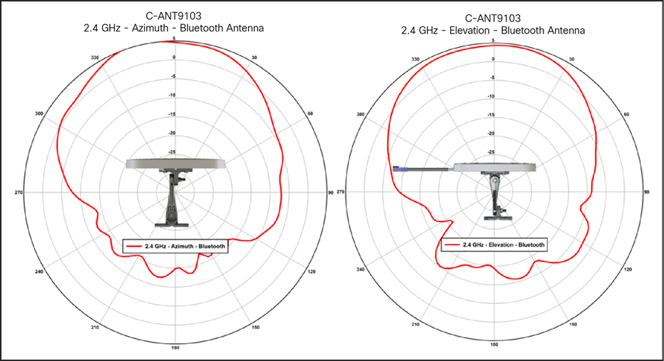
C-ANT9103 antenna patterns, 2.4-GHz BLE/IoT
External antennas supported on the Cisco Catalyst 9130E
Table 3. External antennas
| Part number |
Description |
Gain |
| C-ANT9101= |
Ceiling Mount Omni Self-Identifying Antenna with Bluetooth, 8-port, with DART connectors. |
4 dBi (2.4 GHz) 4 dBi (5 GHz) |
| C-ANT9102= |
Pole or Wall Mount Onmi Self-Identifying Antenna with Bluetooth, 8-port, with DART connectors. |
4 dBi (2.4 GHz) 4 dBi (5 GHz) |
| C-ANT9103= |
Pole or Wall mount 75° Directional Self-Identifying Antenna with Bluetooth, 8-port, with DART connectors. |
6 dBi (2.4 GHz) 6 dBi (5 GHz) |
| AIR-ANT2513P4M-N= |
Patch Antenna, 4-port, with N connectors Note: Connect to AP using AIR-CAB003-D8-N=. |
13 dBi (2.4 GHz) 13 dBi (5 GHz) |
| AIR-ANT2524V4C-R |
Ceiling Mount Omni Antenna, 4-port, with RP-TNC connectors Note: Connect to AP using AIR-CAB002-D8-R=. |
2 dBi (2.4 GHz) 4 dBi (5 GHz) |
| AIR-ANT2524V4C-RS= |
Ceiling Mount Omni Self-Identifying Antenna, 4-port, with RP-TNC connectors. |
2 dBi (2.4 GHz) 4 dBi (5 GHz) |
| AIR-ANT2544V4M-R |
Wall Mount Omni Antenna, 4-port, with RP-TNC connectors. Note: Connect to AP using AIR-CAB002-D8-R=. |
4 dBi (2.4 GHz) 4 dBi (5 GHz) |
| AIR-ANT2544V4M-RS= |
Wall Mount Omni Self-Identifying Antenna, 4-port, with RP-TNC connectors. |
4 dBi (2.4 GHz) 4 dBi (5 GHz) |
| AIR-ANT2566D4M-R |
60° Patch Antenna, 4-port, with RP-TNC connectors.1 Note: Connect to AP using AIR-CAB002-D8-R=. |
6 dBi (2.4 GHz) 6 dBi (5 GHz) |
| AIR-ANT2566D4M-RS= |
60° Patch Self-Identifying Antenna, 4-port, with RP-TNC connectors |
6 dBi (2.4 GHz) 6 dBi (5 GHz) |
| AIR-ANT2566P4W-R= |
Directional Antenna, 4-port, with RP-TNC connectors. Note: Connect to AP using AIR-CAB002-D8-R=. |
6 dBi (2.4 GHz) 6 dBi (5 GHz) |
| AIR-ANT2566P4W-RS= |
Directional Self-Identifying Antenna, 4-port, with RP-TNC connectors |
6 dBi (2.4 GHz) 6 dBi (5 GHz) |
Dual 5-GHz operation and external antennas
As previously mentioned, the AIR-ANT9101, AIR-ANT9102, and AIR-ANT9103 do not support dual 5-GHz modes, as these antennas are smaller in physical design and lack sufficient RF isolation for dual 5-GHz operation.
While other antennas supporting dual 5-GHz operation are under development, the current approach with dual 5 GHz is to use the 9130I (internal antenna model) or, when using the 9130E, to use the smart DART-8 adapter, which allows many of the current antennas listed in the table above to be used in dual 5-GHz mode.
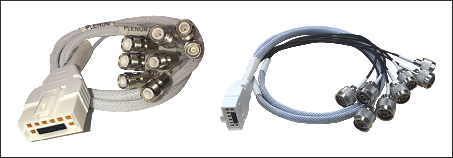
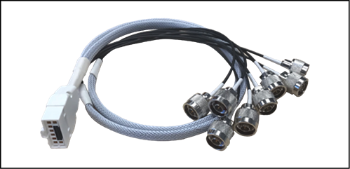
Left: AIR-CAB-002-D8-R= (RP-TNC connectors); right: AIR-CAB-003-D8-N= (“N”-type connectors)
Let’s look at how the DART adapter separates the cables into two groups of four antennas.
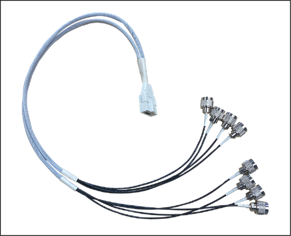
DART adapter and RF connections
| Dart Label |
RF Connection |
| A |
2.4 / 5 GHz (Dual-Band) |
| B |
2.4 / 5 GHz (Dual-Band) |
| C |
2.4 / 5 GHz (Dual-Band) |
| D |
2.4 / 5 GHz (Dual-Band) |
| E |
5 GHz |
| F |
5 GHz |
| G |
5 GHz |
| H |
5 GHz |
The Cisco DART cable assemblies allow for two groups of four antennas. Each connector is labeled.
In dual 5-GHz mode, ports A through D are 2.4 and 5 GHz (4x4 mode), and ports E through H are a secondary 5-GHz radio.
Directional antennas can then be used, sending 2.4 or 5 GHz in one direction and the secondary 5 GHz in a totally different direction.
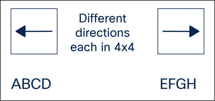
Using directional antennas with the DART adapter
This external antenna flexibility allows for any combination of micro and macro cells, as well as coverage in different cell areas if desired (indoor/outdoor), such as a hospital room with one set of radios and the hallway with the other. True RF flexibility is possible using the DART cable adapter.
It is important, however, to separate the discrete 4x4 antennas away from each other so they do not cause degradation. It helps to use directional antennas or, if using omnidirectional antennas, to have proper spacing (minimum of 2 meters). Below are some general thoughts regarding isolation.
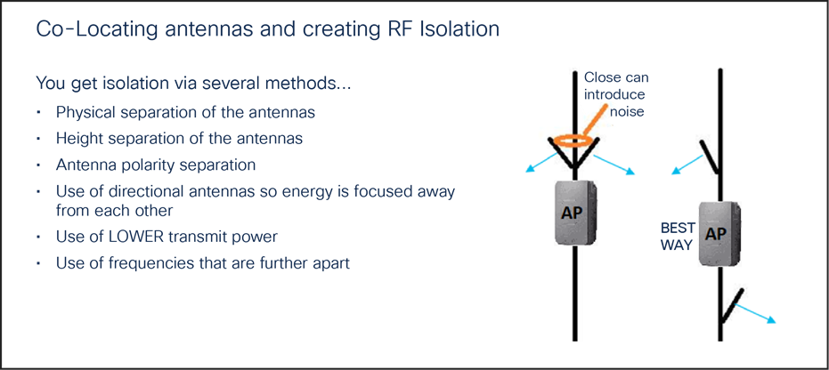
Creating RF isolation
Mount antennas away from each other whenever possible, and follow the isolation guidelines in the section below on FRA and dual 5-GHz operations.
Understanding flexible radio assignment
The Cisco Catalyst 9130 Series Access Points have a Flexible Radio Assignment (FRA) feature. The AP is a tri-band radio, as it contains a dedicated flexible 8x8 5-GHz radio that can, if desired, be split into two separate 4x4 radios (allowing the access point to support two different 5-GHz 4x4 radios that can be configured independently to serve clients).
Unlike previous Cisco products that disabled the 2.4-GHz radio when going into dual 5-GHz mode, the 9130 Series access points have a dedicated 2.4-GHz radio that is also active (regardless of the 5-GHz state) and shares the primary four dual-band antennas (ports A through D) with the 5-GHz radio, so 2.4-GHz 4x4 operation can function simultaneously.
When operating in dual 5-GHz mode, the primary antenna ports A through D operate in dual-band mode, supporting both 2.4 GHz and 5 GHz simultaneously.
Managing dual 5-GHz cells is one of the most important things that FRA does. There are two modes of operation for dual 5-GHz APs:
● Macro/micro: A large cell with a smaller internal cell, creating double the capacity within the boundaries of a single cell.
● Macro/macro: Dual independent 5-GHz cells, doubling the coverage of a single traditional dual-band AP. Macro/macro mode is supported only on the 9120AXE and 9130E (as external antennas are used to accomplish this).
Macro/micro mode is a use case applicable to the Cisco Catalyst 9130I model, as the internal antennas are designed to support a cell-within-a-cell deployment. For this to be effective, much design is committed to isolating the two cells, starting at the silicon and ending with separation in antenna polarity and frequency separation.
FRA and DCA will enforce many configuration requirements when operating as dual 5-GHz macro/micro:
● Minimum 100-MHz channel separation (frequency diversity)
● Micro-cell power is restricted to minimum
● Same Service Set Identifiers (SSIDs) on each cell
Having a macro/micro cell architecture is attractive because it solves the problem of having one large cell in which a very diverse client experience exists. Clients closer to the AP are using higher data rates and enjoy a higher Signal-to-Noise Ratio (SNR) than will clients at the edge of the cell. Macro/micro mode allows isolation of different clients within the cell that can serve them best and preserves airtime by increasing overall efficiency.
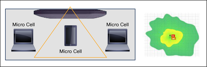
Macro and micro cells
Take-away: A dual 5-GHz-capable Cisco Catalyst 9130I creating micro and macro cells can perform much as two independent 5-GHz access points would, using all the features and benefits of Wi-Fi 6.
When the 9130I is operating in dual 5-GHz mode, clients get equal airtime, lower channel utilization rates, faster client-connected data rates, and fewer retries.
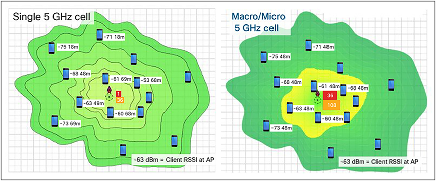
Single 5-GHz channel and dual 5-GHz channels
Left: Single-channel model – utilization is at 60 percent on channel 36
Right: Dual-channel model – channel 36 drops to 20 percent and channel 108 is at 24 percent
In the figure above, on the left a single channel cell, channel 36, has a channel utilization of 60 percent because all clients are connected to that one channel. To make matters worse, they connect at nonuniform speeds, as the close-in clients connect much faster than the far-away clients.
In the dual-channel model on the right, the improvements achieved by using two channels become clear. This results in far less contention and fewer retries and a far better user experience.
Note: This feature was first introduced in the Aironet 2800 and 3800 Series, which won Cisco’s Pioneer Award for innovation in engineering design in 2017. This mode has a very big advantage for reducing channel utilization when combined with Wi-Fi 6 features that help with latency and small packets.
Take-away: Using dual 5 GHz, users experience faster throughput, fewer retries, and a better Wi-Fi experience due to faster data rates and less channel utilization.
CleanAir spectrum analysis using Cisco’s RF ASIC
Cisco CleanAir technology is a custom hardware and software solution.
To overcome the visibility limitations inherent to standard Wi-Fi chipsets, Cisco has created an integrated solution with patented chips and software that has been specifically designed to analyze and classify all RF activity. (More than 25 patents have been issued for this technology to date.)
Essentially, Cisco has taken the technology behind the Cisco Spectrum Expert analysis tool and integrated it directly into the infrastructure, including deep integration with a dedicated Software-Defined Radio (SDR) and a custom RF ASIC. This is a significant development and clearly demonstrates that wireless has transitioned from nice-to-have to business-critical in the enterprise.
The custom solution starts with the Cisco SAgE hardware core, which has been integrated directly into the Cisco RF ASIC custom silicon. The SAgE core handles very compute-intensive operations, such as high-resolution Fast Fourier Transform (FFT) and pulse detection operations. (A pulse is a burst of RF energy in frequency and time.) The SAgE core has a highly granular spectral resolution of 78.125 kHz (4 times better than the nearest competitive solution and 64 times better than most chipsets).
The RF ASIC provides the AP with an advanced and comprehensive interference analysis, detection, and mitigation system. Essentially, the SAgE core handles a base level of spectrum analysis operations that are so processing-intensive that they can be prohibitive to handle in real-time software or by the serving radios.
Benefit: Comprehensive RF analysis and insight into the spectrum that no other competitor has, clearly identifying interference on a dedicated SDR (separate from the client-serving radios) so as to not impact access point client-serving performance.
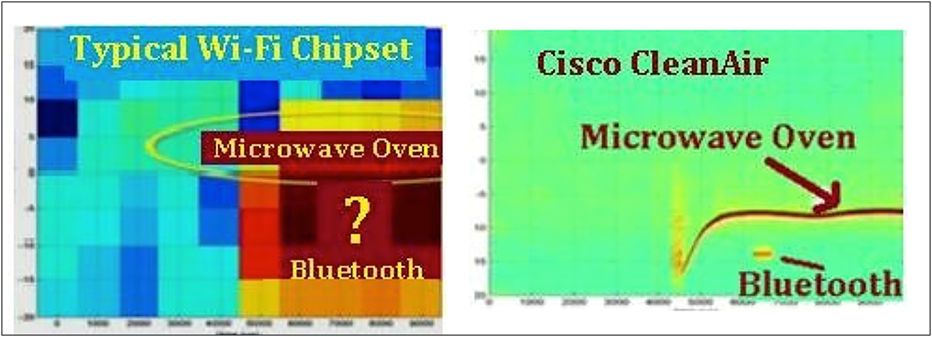
CleanAir clearly identifies the interference, using a dedicated radio and custom silicon
The RF ASIC and CleanAir chipset augment the determination of DFS signals, enhancing DFS and reducing DFS false alerts so the AP can stay on a DFS channel more robustly. In addition, the dedicated radio participates in Cisco’s RRM for interference mitigation and best channel selection.
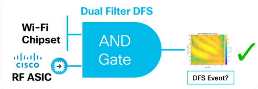
A DFS event (detected by Wi-Fi chipset) is compared to the RF ASIC to verify that it is indeed a real DFS event
The RF ASIC is far more advanced than the DFS detection used by the Wi-Fi chipset and serves as a “second set of eyes” into the spectrum. The RF ASIC as a dedicated SDR will be enhanced further with new features as future software upgrades are released.
Cisco Connected Mobile Experiences (CMX) FastLocate technology enables quick location refresh for connected Wi-Fi clients. The Received Signal Strength Indicator (RSSI) from data packets and probe frames, when available, is used for calculating a location. This technology is available with both centrally switched WLANs and Cisco FlexConnect® (locally switched WLANs).
Benefit: The Cisco Catalyst 9130 Series, with its onboard RF ASIC monitoring radio, enhances location by allowing access points on different client-serving channels to use the RF ASIC to listen to the probes and data packets on the Wi-Fi client of interest, regardless of its channel.
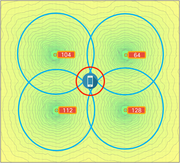
The RF ASIC radio can track Wi-Fi clients regardless of the serving channel
Manufacturing, warehouses, and factories
Warehouse installations are often difficult because of the very high ceilings and the clutter of the material being warehoused. When performing a coverage check (site survey), always check the coverage at “full stock” levels, as the material being warehoused can change the RF coverage, creating loss of uniform coverage. Also, try to position the APs as close to the users as possible, perhaps lowering the antennas when possible. If the AP is 30 feet in the air, that is 30 feet farther the signal has to go, in the best case. When configuring coverage for aisles, try to use directional (patch) antennas on the wall and shoot down the aisles, or use low-gain omnidirectional antennas on the ceiling (such as dipoles) or units with integrated antennas, as high-gain omnidirectional antennas tend to have more nulls.
Another option is to mount the AP lower using pipe and electrical box mounting techniques. Refer to the example below.
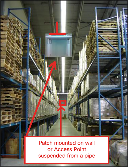
AP placement in a warehouse environment
(An external dipole “e” series or internal antenna “i” series version could be used.)
When mounting an AP at the end of a pipe or electrical conduit box, use the universal bracket Cisco AIR-AP-BRACKET-2, as it will mate to the holes of most electrical boxes. Conduit and adapters can be purchased at most electrical or home repair centers.
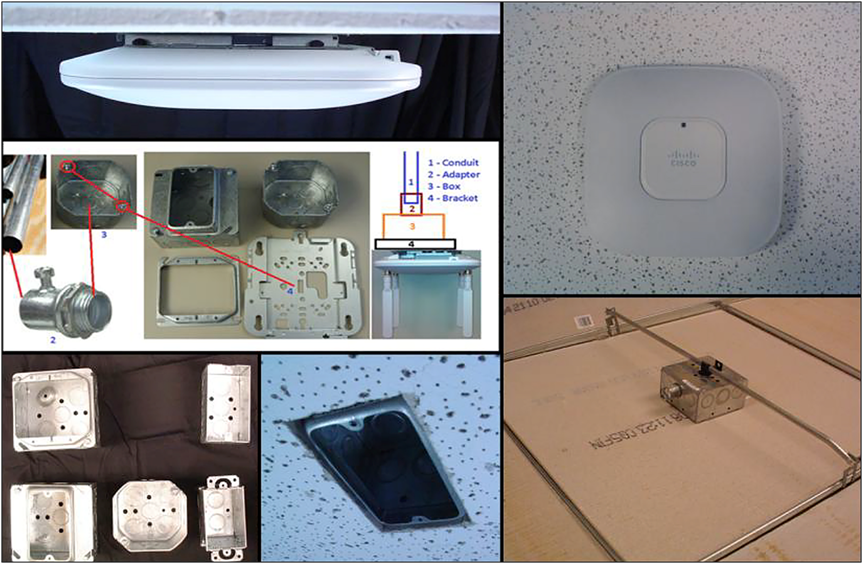
Mounting an AP onto an electrical conduit box (ceiling T-bar or conduit)
Healthcare/clean rooms
If the Cisco Catalyst 9130 Series is used in a clean room, hospital, or other area where the need for infection control requires the access point to be wiped down with a chemical, it is recommended that a ready-to-use sterilant such as Steris Spor-Klenz be used. Unlike some access points, the 9130 Series does not have vent holes in the construction, so it may be wiped down. The plastics have been tested with this sterilant.
Steris Spor-Klenz: https://www.sterislifesciences.com/products/surface-disinfectants/sporicide-cleaners-and-sterilant/spor-klenz-ready-to-use-cold-sterilant
If the healthcare environment has metal ceilings or areas where tile is not practical, a metal enclosure from Oberon or AccelTex can be used.
Oberon metal enclosure protects and secures the AP in clean room areas
Stadiums and harsh environments
Customers wishing to install the AP in harsh environments where it may be exposed to weather, such as sporting areas, stadiums, open garden areas, or warehouse freezers, may wish to use a NEMA-type enclosure.
Note: Some access points may not be certified for outdoor deployments in a NEMA enclosure. This varies around the world. For example, some regulatory agencies permit AP outdoor NEMA enclosures if the AP is indoors, such as in a freezer or garden area, but may prohibit its use outdoors. This seems to vary with weather radar compliance in different countries and often with UNII-1 compliance. Check with your Cisco account team or the communications regulatory agency that has jurisdiction in your part of the world.
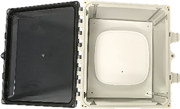
Example of an AccelTex 12x10x6 NEMA enclosure
Third-party sources for NEMA type enclosures and other accessories include:
When using a NEMA-type enclosure, try to have the cables exit out of the bottom of the enclosure so that rain and moisture do not run down the cable into the enclosure. Also, the color of the enclosure may affect the heat rating. For example, a black enclosure gets much hotter in the sun than a white one. You may also want to use a pressure vent to prevent moisture accumulation.
Education/schools
See the deployment guide at the following URL:
Installations in Intermediate Distribution Frame (IDF) closets (telecommunications or other electrical equipment)
When installing APs near other electrical or telecommunications equipment, keep all wiring and metal away from the antennas and avoid placing the antennas near electrical lines. Do not route electrical or Ethernet wiring in the near field (6 to 15 inches) of the antenna. Try to refrain from installing the AP in the electrical closet, as the best place for it is as close to the users as possible or practical. If you must remote antenna cables from such a closet, you may be required to use plenum-rated cable (see local fire/safety regulations for more on this).
Below are a few URLs for understanding interference:
https://www.cisco.com/warp/public/cc/pd/witc/ao1200ap/prodlit/wrlan_wp.pdf
https://www.cisco.com/en/US/prod/collateral/wireless/ps5678/ps10981/white_paper_c11-609300.html
Installations inside and around elevators
Elevator coverage can sometimes be accomplished by placing APs in the near field of the elevator, typically on each floor near the elevator door. Since elevators often have metal doors and the shafts are often concrete or contain other materials that degrade Wi-Fi coverage, it is important to check the coverage inside the elevator. While such coverage can be challenging, it is often doable, especially if the elevator is only a few floors.
High-rise elevators are more challenging, since roaming issues are problematic as the client is cycling through a large number of APs rather quickly. Some companies that do in-elevator advertising have put a patch antenna on the floor inside the shaft and a patch antenna (or the actual AP) on the bottom of the elevator car, while other companies have used leaky coaxial cable running on the side of the shaft.
When installing any Wi-Fi equipment inside elevator cars or shafts, local regulations need to be followed, as many times such installations are prohibited either for safety reasons or because the building owner or local fire department may prohibit them. Also, it is dangerous, and only elevator repair persons or contractors experienced with this kind of work should be in those areas. When external antennas are required, again position and use the 9130E model.
Access point antenna placement
The Cisco Catalyst 9130I Access Point has an advanced antenna system, but correct placement of the AP is critical.
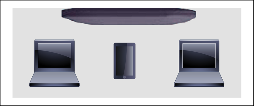
Coverage is optimized for ceiling placement and radiates omnidirectionally
General design guidelines: Access point spacing recommendations
If you have a Wi-Fi device such as an AP, and you are going to use another AP in the vicinity on a different channel, it is recommended that you space the APs approximately 6 feet (2 meters) apart. Avoid clustering the APs or the antennas from different APs together, as this could cause degradation in performance. This recommended distance is based on the assumption that both devices operate in the unlicensed band and do not transmit RF energy more than 23 dB – that is, 200 mW. If higher power is used, space them farther apart.
Should you have other devices that transmit, especially if they operate in the same frequency ranges, for example, frequency-hopping legacy APs or other devices that operate close in frequency to those of the AP (think below or above the 2.4- and 5-GHz bands), you should consider moving or separating the devices as far apart as can reasonably be done. After you have done this, check for interference by testing both devices at the same time under heavy utilization (load) and then characterize each system independently to see how much, if any, degradation exists.
| Warning |
| In order to comply with FCC, EU, and EFTA RF exposure limits, antennas should be located a minimum of 7.9 inches (20 centimeters) or more from the body of all persons. See the installation guide under “Declaration of Conformity” for more on this. |
Mixing access points of different models and types
The Cisco Catalyst 9130 Series are very advanced access points supporting Wi-Fi 6 features along with unique features such as dual 5 GHz and advanced RF detection using Cisco custom RF ASIC silicon.
For this reason, it is not recommended that you mix access point models, sometimes referred to as a “salt and pepper” approach, as the 9130 Series can make spectrum decisions, such as dual DFS detection, that other access points do not partake in.
For this reason, if you have a mixture of AP types, it is recommended that you group like access points together (for example, Aironet 3800 Series on one floor and Cisco Catalyst 9130 Series on another) and refrain from mixing them.
The following are some guidelines to remember regarding access point installations.
● Always try to mount the AP as close to the users as possible for best performance. Be aware of the environment (for example, hospitals have metal doors, coverage can change when the doors close, and old buildings can have metal gridwork in the plaster or asbestos). Avoid mounting the AP or antennas near metal objects, as doing so can change the coverage area, affecting clients.
● When using the 2.4-GHz frequency, the same 1-, 6-, and 11-channel scheme is used as in the 5-GHz channel scheme. Avoid putting all of the APs on the same channel, and reuse channels as you can.
● Cisco RRM, FRA, and other features can help automate the process.
● Try to determine which clients are heavily used, checking the coverage with those clients. For example, a PDA or Wi-Fi phone might not have the same range as a notebook or tablet.
| Verify coverage using the worst-performing clients that you intend to deploy. |
● While site surveys are highly recommended, if the design is done at half power and Cisco RRM is in place, sometimes a limited site survey (coverage check) is adequate for smaller venues. If this is a very challenging environment, such as train connectivity, oil or gas sites, or large hospitals, Cisco has an Advanced Services team that can be contracted to help you get up to speed or perform your installation. See your Cisco account team for more information.
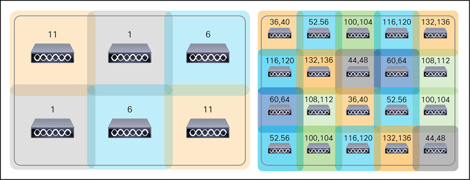
Example of a channel coverage model spacing nonoverlapping channels
Whenever practical or possible, keep antenna cable runs as short as possible. Cisco offers Low-Loss (LL)
and Ultra-Low-Loss (ULL) cables, which have the same characteristics as Times Microwave LMR-400 and LMR-600.
Cisco cables carry the part number AIR-CAB and then a length. For example, a 20-foot length of LL cable with RP-TNC connector is Cisco AIR-CAB-020LL-R. These heavy black cables are not plenum rated and are primarily for outdoor use or manufacturing areas.
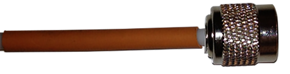
A Cisco cable with RP-TNC connector
When drilling holes for cable, allow for the size of the connector (typically a 5/8-inch drill bit if RP-TNC, above). Other connectors such as “N” style and DART are larger in size.
Wi-Fi 6 installations and site survey considerations
What do you have installed today? Now is the time to evaluate your WLAN needs.
● Before refreshing to Wi-Fi 6, it’s time to do a review of your existing WLAN issues as well as identifying any new location, BLE, or IoT requirements.
● One-to-one replacement assumes that the AP was installed in the best place to meet your current coverage and density goals.
● Do you have any coverage issues today that you have not addressed?
● Are there any poorly mounted or suboptimal installations?
● Ideally, you should have at least 802.3at (30W PoE) available.
● Wi-Fi 6 might help mitigate a poor design, but nothing beats installing it right the first time.
There are many tools out there to model and perform site surveys. Cisco has recently worked with Ekahau to import Cisco APs and antenna models into their application, which also includes the ability to model BLE.

Ekahau offers a site survey and WLAN planner software
If you are doing an active survey for placement, it is always best to have the equipment you plan to deploy. Having the actual model that is being planned for is not always possible at the time the planning is being done. Cisco spends a great deal of effort to ensure that newer-model APs’ RF coverage matches closely with previous AP models to reduce the cost of planning and replacing APs. The Cisco Catalyst 9130 Series is no different. The figure below shows the Cisco Catalyst 9120AX Series as compared with the Aironet 3802i on the same channel and power, as an example only. Surveying using an alternate AP is suitable for Bill Of Materials (BOM) generation or updates to an existing installation. Critical coverage should always be measured using the same model to be certain of the results.
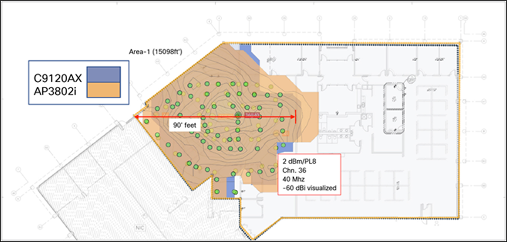
Comparison of Cisco Catalyst 9120AX Series and Aironet 3802i coverage patterns as measured over the air
Note: The cell sizes in the figure above also apply to the Cisco Catalyst 9130 Series, as it has similar cell sizes.
If the building is not wired for Ethernet and you need to power a Cisco Catalyst 9130 Series Access Point from a battery, AccelTex offers a battery pack that can be used.
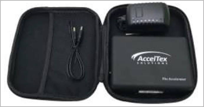
AccelTex site survey battery pack P/N ATS-SSBP-1
Useful URLs:
● Cisco CleanAir white paper: https://www.cisco.com/c/en/us/solutions/collateral/enterprise-networks/cleanair-technology/white_paper_c11-599260.html
● Flexible Radio Assignment and dual 5-GHz operation: https://www.cisco.com/c/en/us/td/docs/wireless/controller/technotes/8-3/b_RRM_White_Paper/b_RRM_White_Paper_chapter_01000.html
● Flexible radio Cisco Aironet 2800/3800 Series deployment guide: https://www.cisco.com/c/en/us/td/docs/wireless/controller/technotes/8-3/b_cisco_aironet_series_2800_3800_access_point_deployment_guide.pdf
● Cisco Multigigabit overview, along with supported switches: https://www.cisco.com/c/en/us/solutions/enterprise-networks/catalyst-multigigabit-switching/index.html
● Cisco DNA overview: https://www.cisco.com/c/dam/en/us/solutions/collateral/enterprise-networks/cisco-digital-network-architecture/solution-overview-c22-736580.pdf