Cisco TrustSec

This chapter explains configuring and enforcing Cisco TrustSec features: SGTs, SGACLs, inline tagging, SXP, and ISE integration on Cisco Catalyst 9800 controllers and APs to implement role-based, topology-independent access control.

Cisco TrustSec

A Cisco TrustSec solution is a network security architecture that

  • strongly identifies users, hosts, and network devices within the network

  • provides topology-independent and scalable access controls by classifying data traffic based on user or device roles, and

  • ensures data confidentiality and integrity by establishing trust among authenticated peers and encrypting network links.

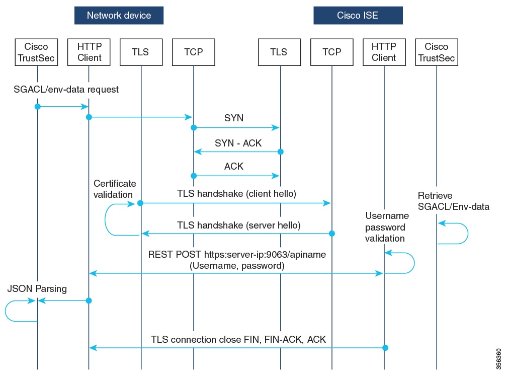
The key component of Cisco TrustSec is the Cisco Identity Services Engine (ISE). Cisco ISE can provision switches with TrustSec Identities and Security Group ACLs (SGACLs). SGACLs may be configured manually on the switch.


Note


Before changing CTS server to a new one, manually clear the CTS environment data using the clear cts environment-data command. Running the show cts environment-data command will return updated data.


Feature History

Feature Name

Release

Description

Trustsec policy HA support for FlexConnect mode APs

Cisco IOS XE 17.18.2

The feature ensures that CTS SGACL enforcement remains available and consistent during HA events such as Stateful Switchover (SSO) between wireless controllers. This provides uninterrupted security policy enforcement on Flex mode APs even during controller failover or redundancy events.

TrustSec support for Cisco Catalyst IW6300 Heavy Duty Series and 6300 Series Embedded Services APs

Cisco IOS XE 17.8.1

Enable and configure Cisco TrustSec Security Group ACL (SGACL) in FlexConnect and Flex+Bridge mode. SGACL enforcement on the controller is available for local and Bridge mode. Inline tagging and SXP are supported only in FlexConnect.

Support for SGT Inline Tagging Over Port-Channel Uplink

Cisco IOS XE 17.3.5a

SGT inline tagging over port-channel uplink is supported for Cisco Catalyst 9800-L, 9800-40, and 9800-80 Wireless Controllers.

If you downgrade to releases that do not support SGT inline tagging over port-channel, the port-channel may be suspended.

Cisco TrustSec features

This table lists the TrustSec features that will be implemented on TrustSec-enabled Cisco switches. Future releases will support more switches and provide additional TrustSec features.

Cisco TrustSec Feature Description
802.1AE Tagging (MACsec)

Protocol for IEEE 802.1AE-based wire-rate hop-to-hop Layer 2 encryption.

On MACsec-capable devices, your network traffic is encrypted when leaving one device, decrypted when entering the next device, while staying unencrypted inside the devices.

This feature is only available between TrustSec hardware-capable devices.

Endpoint Admission Control (EAC)

EAC authenticates each device or user connecting to the TrustSec domain. This usually happens at the access level switch. If authentication and authorization are successful, your device or user session receives a Security Group Tag. You can use 802.1X, MAC Authentication Bypass (MAB), or Web Authentication Proxy (WebAuth) with EAC.

Network Device Admission Control (NDAC)

With NDAC, each network device in your TrustSec domain verifies the credentials and trustworthiness of peer devices. NDAC uses an authentication framework based on IEEE 802.1X port-based authentication and EAP-FAST as its EAP method. Successful authentication and authorization in NDAC process results in Security Association Protocol negotiation for IEEE 802.1AE encryption.

Security Group Access Control List (SGACL)

Security Group Access Control List (SGACL): An SGACL links a Security Group Tag with a policy that your devices enforce on SGT-tagged traffic leaving the TrustSec domain.

Security Association Protocol (SAP)

After NDAC authentication, the Security Association Protocol (SAP) automatically negotiates keys and the cipher suite for subsequent MACSec link encryption between TrustSec peers. SAP is defined in IEEE 802.11i.

Security Group Tag (SGT)

An SGT is a 16-bit label indicating the security classification of a source in the TrustSec domain. It is appended to an Ethernet frame or an IP packet.

SGT Exchange Protocol (SXP)

Security Group Tag Exchange Protocol (SXP). With SXP, devices that are not TrustSec-hardware-capable can receive SGT attributes for authenticated users and devices from the Cisco Identity Services Engine (ISE) or the Cisco Secure Access Control System (ACS). The devices can then forward a sourceIP-to-SGT binding to a TrustSec-hardware-capable device will tag the source traffic for SGACL enforcement.

When both ends of a link support 802.1AE MACsec, SAP negotiation occurs. An EAPOL-key exchange occurs between the supplicant and the authenticator to negotiate a cipher suite, exchange security parameters, and manage keys. Successful completion of these tasks results in the establishment of a security association (SA).

Depending on your software version, licensing, and link hardware support, SAP negotiation can use one of these modes of operation:

  • Galois Counter Mode (GCM): authentication and encryption

  • GCM authentication (GMAC): GCM authentication, no encryption

  • No Encapsulation: no encapsulation (clear text)

  • Null: encapsulation, no authentication or encryption

Configure a device SGT manually (CLI)

Configure a device Security Group Tag (SGT) using commands when the authentication server is unavailable.

When the authentication server is accessible, it assigns an SGT to your device for packets originating from your device. If the authentication server is not available, configure an SGT manually. The server-assigned SGT is always used instead of your manual configuration if both are present.

Procedure


Step 1

Enter the global configuration mode.

Example:

Device# configure terminal

Step 2

Configure a WLAN policy profile and enter the wireless policy configuration mode.

Example:

Device(config)# wireless profile policy profile-policy

Step 3

Specify the Security Group Tag (SGT) number.

Example:

Device(config-wireless-policy)# cts sgt sgt-value

The valid values are from 0 to 65,535.

Step 4

Return to the global configuration mode.

Example:

Device(config-wireless-policy)# exit

Configure ISE for TrustSec (CLI)

Set up ISE to enable secure network access using TrustSec policies using commands.
This task involves configuring a device to communicate with an ISE server as a RADIUS server and integrating TrustSec authorization.

Procedure


Step 1

Enter the global configuration mode.

Example:

Device# configure terminal

Step 2

Specify the RADIUS server name.

Example:

Device(config)# radius server server-name

Step 3

Specify the primary RADIUS server parameters.

Example:

Device(config-radius-server)# address ipv6 ip-address

Step 4

Specify the authentication and encryption key used between the Device and the key string RADIUS daemon running on the RADIUS server.

Example:

Device(config-radius-server)# pac key key

Step 5

Return to the configuration mode.

Example:

Device(config-radius-server)# exit

Step 6

Create a radius server-group identification.

Example:

Device(config)# aaa group server radius server-group

Note


server-group refers to the server group name. The valid range is from 1 to 32 alphanumeric characters.

Step 7

Create a CTS authorization list.

Example:

Device(config)# cts authorization list mlist-name

Step 8

Create an authorization method list for web-based authorization.

Example:

Device(config)# aaa authorization network mlist-name group group-name

Note


Ensure that the ISE IP address configured on your controller is the same as the IP address configured on ISE ( Work Center > TrustSec > Components > Trustsec AAA Servers ).

Note


If the ISE version is 002.005(000.239), 002.004(000.357), 002.003(000.298), 002.002(000.470), 002.001(000.474), 002.000(001.130), or 002.000(000.306), use the access-session tls-version 1.0 command to download PAC from ISE. For other ISE versions, the above command is not required.


Verify Cisco TrustSec configuration

To display the wireless CTS SGACL configuration summary, use this command:

Device# show wireless cts summary

Local Mode CTS Configuration

Policy Profile Name               SGACL Enforcement     Inline-Tagging   Default-Sgt      
----------------------------------------------------------------------------------------
xyz-policy                        DISABLED              ENABLED          0                
wireless-policy1                  DISABLED              DISABLED         0                
w-policy-profile1                 DISABLED              DISABLED         0                
default-policy-profile            DISABLED              DISABLED         0                


Flex Mode CTS Configuration

Flex Profile Name                 SGACL Enforcement     Inline-Tagging   
-----------------------------------------------------------------------
xyz-flex                          DISABLED              ENABLED          
demo-flex                         DISABLED              DISABLED         
flex-demo                         DISABLED              DISABLED         
xyz-flex-profile                  DISABLED              DISABLED         
default-flex-profile              DISABLED              DISABLED         


To display CTS-specific configuration status for various wireless profiles, use this command:

Device# show cts wireless profile policy xyz-policy

Policy Profile Name         		: xyz-policy
CTS
  Role-based enforcement         : ENABLED
  Inline-tagging                 : ENABLED
  	Default SGT		 : 100

Policy Profile Name          		: foo2
CTS
  Role-based enforcement         : DISABLED
  Inline-tagging                 : ENABLED
  Default SGT		         : NOT-DEFINED

Policy Profile Name           	        : foo3
CTS
  Role-based enforcement         : DISABLED
  Inline-tagging                 : DISABLED
  Default SGT			 : 65001

To display CTS configuration for a given wireless profile, use this command:

Device# show wireless profile policy detailed xyz-policy
 
Policy Profile Name           : xyz-policy
Description                   : 
Status                        : DISABLED
VLAN                          : 1
Client count                  : 0
Passive Client                : DISABLED
ET-Analytics                  : DISABLED
StaticIP Mobility             : DISABLED
!
.
.
.WGB Policy Params
  Broadcast Tagging           : DISABLED
  Client VLAN                 : DISABLED
Mobility Anchor List
  IP Address                                  Priority
CTS
  Role-based enforcement         : ENABLED
  Inline-tagging                 : ENABLED
  Default SGT	                  : NOT-DEFINED

Security Group Access Control List (SGACL)

A security group access control list (SGACL) is a network security policy mechanism that

  • enforces access control between groups of users, devices, and resources based on their assigned security group

  • simplifies policy management by using unique security group tags (SGTs) to dynamically control permissions, and

  • reduces administrative overhead by decoupling access policies from the network topology or addressing.

Security groups are defined by the administrator in Cisco Identity Services Engine (ISE). As new users and devices are added to the Cisco TrustSec domain, the authentication server assigns these new entities to the appropriate security groups. Cisco TrustSec assigns each security group a unique 16-bit number that is globally scoped within a Cisco TrustSec domain. The number of security groups on a wireless device is limited by the number of authenticated network entities. You do not need to configure the security group numbers manually.

After a device is authenticated, Cisco TrustSec tags each packet originating from that device with an SGT containing the device's security group number. The packet carries this SGT everywhere in the network, in the Cisco TrustSec header.

As the SGT contains the security group of the source, the tag can be referred to as the source SGT (S-SGT). The destination device is also assigned to a security group (destination SG) that can be referred to as the destination SGT (D-SGT), even though the Cisco TrustSec packet does not contain the security group number of the destination device.

You can control the operations that users can perform based on the security group assignments of users and destination resources, using the Security Group Access Control Lists (SGACLs). Policy enforcement in a Cisco TrustSec domain is represented by a permission matrix, with the source security group numbers on one axis and the destination security group numbers on the other axis. Each cell in the matrix body contains an ordered list of SGACLs, which specify the permissions that must be applied to packets originating from the source security group and destined for the destination security group. When a wireless client is authenticated, the controller downloads all the SGACLs in the matrix cells.

When a wireless client connects to the network, the client pushes all the ACLs to the controller .

Cisco TrustSec achieves role-based topology-independent access control in a network by assigning users and devices in the network to security groups and applying access control between the security groups. The SGACLs define access control policies based on the device identities. The security policy remains unchanged if the roles and permissions stay the same, even when the network topology changes. Assigning a user to an appropriate security group immediately grants the user permissions for that group when the user is added to the wireless group.

Role-based permissions reduce ACL size and simplify their maintenance. With Cisco TrustSec, the number of Access Control Entities (ACEs) that are configured is determined by the number of permissions specified, resulting in a much smaller number of ACEs.

For a list of Cisco APs that support SGACL, see the release notes.: https://www.cisco.com/c/en/us/support/wireless/catalyst-9800-series-wireless-controllers/products-release-notes-list.html


Note


Clients receive zero SGT value and DHCP clients receive an Automatic Private IP Addressing (APIPA) address when TrustSec policy “unknown to unknown” is denied in TrustSec matrix.

Clients receive correct SGT values and DHCP clients receive an IP address when TrustSec policy “unknown to unknown” is permitted in TrustSec matrix.


Supported SGACL

The scenarios supported for SGACLs on the Cisco Catalyst 9800 Series Wireless Controller are:

  • Wireless-to-wireless (within Enterprise network):

    • In FlexConnect mode with local switching, the egress AP enforces SGACL when a packet moves from a source wireless network to a destination wireless network.

    • In FlexConnect mode with central switching, SGACL enforcement is performed on the egress AP. To achieve this, the controller exports IP address to security group tag (IP-SGT) binding over SGT Exchange Protocol (SXP).

  • Wired-to-wireless (DC-to-Enterprise network): Enforcement occurs when a packet reaches the destination AP.

  • Wireless-to-wired (Enterprise network-to-DC): Enforcement occurs on the uplink switch when a packet reaches the ingress of the wired network.

Guidelines and restrictions of SGACL

These are the guidelines and restrictions of Security Group Access Control List (SGACL).

  • SGACL enforcement is carried out on the controller for local mode.

  • CTS SGACL high availability is available on Flex mode. This provides uninterrupted security policy enforcement on Flex mode APs even during controller failover or redundancy events.

  • SGACL enforcement is carried out on an AP for flex-mode APs performing local switching.

  • SGACL enforcement for wireless clients is carried out either on the upstream switch or on the border gateway in a Branch-to-DC scenario.

  • SGACL enforcement is not supported for non-IP or IP broadcast or multicast traffic.

  • Per-WLAN SGT assignment is not supported. Static SGACL configuration on an AP is not supported.

  • SGACL enforcement is not carried out for control-plane traffic between an AP and the wireless controller (for upstream or from upstream traffic).

  • Non-static SGACL configurations are supported only for dynamic SGACL policies received from ISE.

  • In case of Allow List model, you need to explicitly allow DHCP protocol for the client devices to get the DHCP IP address and then request the controller for SGACL policies.

Enable SGACL on the AP (GUI)

Use the GUI to apply SGACL enforcement to APs as part of your security configuration workflow.

Procedure


Step 1

Choose Configuration > Tags & Profiles > Flex.

Step 2

Click Add.

Step 3

In the General tab, check the Inline Tagging and SGACL Enforcement check boxes and select the CTS profile name from the CTS Profile Name drop-down list.

Step 4

Click Apply to Device.


Enable SGACL on the AP (CLI)

Enable role-based access control on APs for enhanced network security using commands.

Note


Use the no form of the commands given below to disable the configuration. For example, cts role-based enforcement disables role-based access control enforcement for APs.


Before you begin

  • Security Group Access Control List (SGACL) on an AP is enabled only when the wireless controller is in FlexConnect mode.

  • Configure the cts manual command on the uplink port to send or receive a tagged packet.

Procedure


Step 1

Enter the global configuration mode.

Example:

Device# configure terminal

Step 2

Configure an RF profile and enter the RF profile configuration mode.

Example:

Device(config)# wireless profile flex flex-profile

Step 3

Enable role-based access control enforcement for the AP.

Example:

Device(config-wireless-flex-profile)# cts role-based enforcement

Step 4

Enable inline tagging on the AP.

Example:

Device(config-wireless-flex-profile)# cts inline-tagging

Step 5

Enable the CTS profile name and return to the global configuration mode.

Example:

Device(config-wireless-flex-profile)# cts profile profile-name
Device(config-wireless-flex-profile)# exit 

Step 6

Configure a site tag and enter the site tag configuration mode.

Example:

Device(config)# wireless tag site site-name

Step 7

Configure a FlexConnect profile and return to the global configuration mode.

Example:

Device(config-site-tag)# flex-profile flex-profile-name
Device(config-site-tag)# exit 

Step 8

Configure an AP and enter the AP profile configuration mode.

Example:

Device(config)# ap mac-address

Step 9

Map a site tag to an AP.

Example:

Device(config-ap-tag)# site-tag site-tag-name

What to do next

show cts ap sgt-info ap-name command to verify the SGACL configuration on the AP.

Policy enforcement

A policy enforcement mechanism is a network security control that

  • applies access control policies to network traffic using predefined rules

  • uses attributes such as Security Group Tags (SGTs) to dynamically determine permitted actions, and

  • enables context-based enforcement at key points within the network infrastructure.

Cisco TrustSec access control is implemented using ingress tagging and egress enforcement. At the ingress point to the Cisco TrustSec domain, the traffic from the source is tagged with an SGT containing the security group number of the source entity. The SGT is propagated across the domain with the traffic. At the egress point of the Cisco TrustSec domain, an egress device uses the security group of the destination entity (D-SGT) to determine the access policy to apply from the SGACL policy matrix.


Note


A Cisco AP must be in Listener mode or Both (Listener and Speaker) mode to enforce traffic because Listener mode maintains the complete set of IP-SGT bindings. After you enable enforcement on an AP, the corresponding policies are downloaded and pushed to the AP.


SGACL policies for guest wireless clients

A SGACL policy is an access control mechanism that

  • defines the network permissions for wireless guest clients

  • is enforced on the anchor controller in guest mobility scenarios, and

  • uses integration with Cisco ISE for policy download and enforcement.

When a client joins the wireless network (WLAN), its session is managed by the Cisco Catalyst 9800 Series Wireless LAN Controller that the AP is connected to is the foreign controller. Auto-Anchor Mobility allows a specific WLAN (for example, Guest WLAN) to be anchored to a particular controller, regardless of the client’s entry point into the network. Auto-Anchor Mobility is a wireless guest service in which all guest traffic tunnels back to the DMZ controller, regardless of the client's association point on the network.

In case of Auto-Anchor mobility, these apply to Cisco TrustSec support:

  • Classification: Occurs during authentication and hence on Foreign for Layer 2 security WLANs and on Anchor for Layer 3 security cases.

  • Propagation: Always occurs at the Anchor controller where the client traffic enters the wired network.

  • Enforcement: SGACL download and enforcement occur on the Anchor controller; the Anchor controller must have connectivity to Cisco Identity Services Engine (ISE) and be registered as a Network Access Server (NAS). Enforcement is not supported on the Foreign controller even if the enforcement CLI is configured there.

This feature is supported in local mode and in FlexConnect Central Switching of the controller. FlexConnect mode with local switching and Fabric mode are not supported in guest scenarios because traffic does not pass through the controller.

Roaming of a guest client occurs only at the Guest Foreign controller, and the Guest Anchor remains fixed. The two types of supported roaming are inter-controller roaming and intra-controller roaming. Roaming during WebAuth pending is a special case that is also supported for Central Web Authentication (CWA) and Local Web Authentication (LWA).

Enable SGACL policy enforcement globally (CLI)

Enforce Cisco TrustSec SGACL policies on all routed interfaces to provide unified access control for both IPv4 and IPv6 traffic using commands.

You must enable SGACL policy enforcement globally on Cisco Catalyst 9800 Series Wireless Controller. The same configuration commands that are used for enforcement of IPv4 traffic apply for IPv6 traffic as well.

Procedure

Step 1

Enter the global configuration mode.

Example:
Device# configure terminal

Step 2

Enable Cisco TrustSec SGACL policy enforcement on routed interfaces.

Example:
Device(config)# cts role-based enforcement

Enable SGACL policy enforcement per interface (CLI)

Enforce access control policies on selected network interfaces for enhanced security using SGACLs using commands.

After enabling the SGACL policy enforcement globally, enable Cisco TrustSec-on the uplink interfaces.

Procedure

Step 1

Enter the global configuration mode.

Example:
Device# configure terminal

Step 2

Specify interface on which to enable or disable SGACL enforcement.

Example:
Device(config)# interface gigabitethernet interface number

Step 3

Enable Cisco TrustSec SGACL policy enforcement on routed interfaces.

Example:
Device(config-if)# cts role-based enforcement

Step 4

Verify that SGACL enforcement is enabled.

Example:
Device(config-if)# do show cts interface

Inline tagging

An inline tag is a transport mechanism that

  • carries the source SGT in packet headers as wireless traffic moves through the network

  • enables enforcement of Security Group Access Control Lists (SGACLs) by controllers, and

  • supports both centrally and locally switched wireless deployments.

There are two types of transport mechanisms: central switching and local switching.

  • For central switching, the controller performs inline tagging of all packets sourced from wireless clients associated with the controller by tagging these packets with the Cisco Meta Data (CMD) tag. For packets inbound from the distribution system, inline tagging also requires the controller to strip the CMD header from the packet to identify the S-SGT tag. Afterward, the controller forwards the packet, which includes the S-SGT, for SGACL enforcement.

  • To transmit locally switched traffic, an AP performs inline tagging for packets that are associated with the AP and sourced from clients. To receive traffic, the AP handles both locally and centrally switched packets, uses the S-SGT tag, and applies the SGACL policy.

When wireless Cisco TrustSec is enabled on the controller , enabling and configuring SXP to exchange tags with the switches is optional. Both wireless Cisco TrustSec and SXP modes are supported; however, there is no use case for enabling both wireless Cisco TrustSec (on an AP) and SXP concurrently.

Consideration and restriction for inline tagging over port-channel

  • Configure the cts manual command on port-channel and its member interfaces to send or receive a tagged packet.

  • If you downgrade to Cisco IOS XE releases that do not support inline tagging over port-channel, the port-channel may be suspended.


    Note


    Inline tagging over port-channel is supported in Cisco IOS XE 17.3.5 17.6.3 17.8.1 releases.


Configure SGACL, inline tagging, and SGT in local mode (GUI)

Configure SGACL enforcement, inline tagging, and default SGT values in local mode through the GUI.
Enable Security Group Access Control Lists (SGACL), inline tagging, and assign default Security Group Tags (SGT) on a policy profile operating in local mode.
Procedure

Step 1

Choose Configuration > Tags & Profiles > Policy.

Step 2

Click the Policy Profile Name. The Edit Policy Profile is displayed.

Step 3

Choose General tab.

Step 4

In the CTS Policy settings, check or uncheck the Inline Tagging and SGACL Enforcement check boxes, and enter the Default SGT value.

Step 5

Click Update & Apply to Device.


Configure SGACL, inline tagging, and SGT in local mode (CLI)

Use this procedure to configure Secure Group Access Control Lists (SGACL), inline tagging, and Security Group Tag (SGT) enforcement in local mode on a controller using commands.
Procedure

Step 1

Enter the global configuration mode.

Example:
Device# configure terminal

Step 2

Create a policy profile for the WLAN.

Example:
Device(config)# wireless profile policy profile-name

Step 3

Enable CTS inline tagging.

Example:
Device(config-wireless-policy)# cts inline-tagging 

Note


Configure the cts manual on the physical interface. If the cts manual is configured on the physical interface and cts inline-tagging is not enabled, packets remain tagged at egress in the controller.

Step 4

Enable CTS SGACL enforcement.

Example:
Device(config-wireless-policy)# cts role-based enforcement 

Step 5

(Optional) Set the default Security Group Tag (SGT).

Example:
Device(config-wireless-policy)# cts sgt sgt-value

Note


SGT is required for a user session only when the client uses open authentication, and not the ISE server.


SGACL and environment data download over REST

Cisco TrustSec uses the REST-based transport protocol that

  • ensures more secure communication for provisioning Security Group Access Control List (SGACL) policies and environment data compared to older RADIUS protocols

  • provides faster and more reliable policy and data downloads across the network,

  • simplifies integration between Cisco TrustSec and ISE, supporting efficient delivery and enforcement of security group policies.

Both REST API-based and RADIUS-based protocols for downloading Cisco TrustSec data are supported. Only one protocol can be active on a device at a time. You can change the protocol to RADIUS by configuring the cts authorization list command.


Note


Cisco TrustSec Change of Authorization (CoA) will still use RADIUS as the protocol.


Cisco TrustSec SGACL and environment data are synchronized from the active device to the standby device, after the policy is installed. However, REST API connections or sessions are not synchronized during a switchover.

Prerequisites for SGACL and environment data download over REST

To ensure proper operation of SGACL and environment data downloads over REST, observe these requirements:

  • Cisco Identity Services Engine (ISE) must use version 2.7 or later.

  • Cisco TrustSec-enabled devices must use Cisco IOS XE 26.1.1 or later releases.

  • Update the network device configuration on Cisco ISE to allow REST API calls from a network device IP address (NAS-IP). The network device uses the device ID and password specified in the Cisco ISE configuration as its username and password when making REST API calls to Cisco ISE.

Restrictions for SGACL and environment data download over REST

To ensure proper operation of SGACL and environment data downloads over REST, observe these requirements:

  • Cisco TrustSec Change of Authorization (CoA) uses RADIUS as the protocol.

  • Only port 9063 is supported as the ERS server port.

  • Server statistics are not persistent after a refresh of the environment data.

  • Only one Fully Qualified Domain Name (FQDN) per server is supported.

Cisco TrustSec environment data

Environment data comprises of operational data that supplement Cisco TrustSec functions. The environment data request from a device to Cisco ISE consists of:

  • Device name: Specifies the name of the device.

  • Device capability: Specifies additional data.

The environment data response from Cisco ISE to a device consists of:

  • Device security group tag (SGT): Derived from Cisco ISE based on the device name.

  • Server list: Displays the list of Cisco TrustSec servers specified in Cisco ISE.

  • SG-Name Table: Displays the mapping between SGT and the device name. SGT is displayed in numerals and the device name in text format.

  • Refresh time: Indicates the time when the environment data will be refreshed.


Note


  • As part of Cisco TrustSec environment data refresh, the last received servers are deleted and newly received servers are added to the server list. As a result of the refresh, the server list statistics restarts from zero, and the server status is set to Inactive and the IP address state is set to Reachable. The device then updates the server statistics and status based on the subsequent policy request and response.

  • Starting with Cisco IOS XE Bengaluru 17.4.1, you can configure automated tester to be VRF aware. You can use the vrf keyword with the automate-tester command to enable automate-tester for a non-default VRF.

    For VRF aware automate-tester to work, you have to configure global config ipv4/ipv6 source interface interface-name vrf vrf-name command.


Message flow between a network device and a server

Summary

This process outlines how secure REST API communication is managed between a network device and a Cisco Identity Services Engine (ISE) server using TLS and authentication steps.

The key components involved in the process are:

  • Cisco ISE server: Hosts the REST API service and handles incoming requests over secure connections.

  • Network device: Initiates REST API calls to request SGACL and environment data from the server.

  • TLS connection: Ensures encrypted, authenticated communication between the device and the server.

The server terminates the connection through a TCP-FIN message after all REST requests are processed.

Workflow

Figure 1. Figure 1. Message flow between a network device and a server
  1. Cisco ISE REST API service runs on a secure socket using TLS 1.2 on port 9063. This service handles network device requests for SGACL and environment data.
  2. The device uses a make-or-break approach to the TLS connection establishment, and there is no persistent TLS connection between the device and Cisco ISE. The server terminates the connection through a TCP FIN message after all REST requests are processed. For new REST API calls a new connection must be established with the server.
  3. The REST API call from the device to Cisco ISE starts with a TCP connection establishment. Cisco ISE must be configured with device IP address to allow ingress connections from the device. If you send a TCP connection request from a source IP address not configured on Cisco ISE, Cisco ISE drops the request and creates an audit log.
  4. Username and password—Every REST API call must include username and password authentication while requesting access to a resource uniform resource identifier (URI). The authentication helps the server to determine if the caller should be given access to the resource or to deny the request.
  5. "To establish a secure TLS connection with Cisco ISE, you must install its server certificate signature or PEM as the trustpoint on the device. Use the crypto pki trustpoint command for this step. Export and install only the fingerprint or signature of the server certificate on the device under a trustpoint. You do not need to import the server certificate's private key.
  6. After establishing the TLS connection, the HTTP client on the device initiates a REST call to Cisco ISE on the specified resource.

Result

The process allows devices to securely communicate and exchange environment or policy data with Cisco ISE servers by using authenticated and encrypted REST API sessions.

Policy server selection criteria

To explain the criteria and methods used by Cisco TrustSec devices to select a policy server from multiple configured HTTP servers, ensuring efficient communication with Cisco ISE and optimized load distribution.

You can configure multiple HTTP policy servers on your Cisco TrustSec device. After a server is selected, the device uses that server to interact with Cisco ISE until the server is inactive.

There are two types of server selection:

  • In-order selection: This is the default behavior, where servers are picked in the order in which they are configured (from the public server list) or downloaded (from the private server list). After the device selects a server, it continues using that server until it becomes inactive. Then, the device selects the next server in the list.

    When environment data is successfully downloaded, and a server-list is available, these servers are added to the private server list.

  • Random server selection: When multiple HTTP policy servers are configured on a device, a single Cisco ISE instance may get overloaded if the device always selects the first configured server. To avoid this situation, each device will randomly select a server. The device generates a random number, and based on this number, selects a server. For different devices to generate random numbers, the unique board ID and the Cisco TrustSec process ID of the device is used to initialize the random number generator.

    After the device selects a server, it sends all future requests to this server until it becomes inactive. When a server becomes inactive, the device uses the random server selection logic to pick the next available server. The device does not include inactive servers when selecting a new server. The device numbers servers starting at zero.

    Selected Server = (Generated Random Number) % (Total Number of Active Servers).

To change the server selection logic to random, use the cts policy-server order random command.

Server and IP address selection process

Summary

The server and IP address selection process determines how a device chooses which server and IP address to use for connecting to Cisco ISE. This process provides failover, supports IPv4 and IPv6, and prioritizes server lists to ensure reliable connectivity.

Workflow

The order of server selection is the private server list, which is received as part of server list download, followed by the public server list, which contains the configured servers. The device selects a server at random or in order, depending on whether you enable the cts policy-server order random command.

In Cisco IOS XE 17.2.1 and later releases, each server can have multiple IP addresses (both IPv4 and IPv6). The device selects IPv4 addresses first (IPv6 addresses second), and lastly FQDN.

Here is how the device selects a server and IP address:

  • When a device boots up for the first time, a server from the public (configured) list is selected.

  • If the cts environment-data enable command is configured, the device uses the public server to download the private server-list from Cisco ISE.

  • After selecting a server and IP address, the device connects to Cisco ISE using that combination.

  • After the server and IP address are selected, the device connects to Cisco ISE using the server and IP address combination. This server will interact with Cisco ISE until it fails to get a response.

  • If the device does not receive a response from the current active server in the private list, it switches to the next server. When the server is selected for the first time, the device searches for the first reachable IP or IPv6 address.

  • After selecting a server and IP address, the device uses this combination until the device goes down.

  • If none of the servers in the private list are reachable, the device attempts to connect to the servers in the public list. The server switching logic and IP selection are the same for private and public list.

  • The server change happens only when the server list is refreshed.

  • If all servers in both the private and public server list are dead, the device restarts the server and IP address selection logic from the start of the private list.

  • When a specific server and IP address combination fails, the device waits for 60 seconds before it attempts a new combination.

Result

The device reliably connects to Cisco ISE by selecting available servers and IP addresses to maximize resilience and compatibility.

Server liveliness check

Summarize the methods and criteria Cisco ISE uses to assess and respond to server availability in the server selection process.

Cisco ISE determines whether a server is alive after receiving an environment-data or SGACL request. Cisco ISE does not run a liveliness detection phase on the server after it is configured or downloaded as part of a server list. By default, Cisco ISE considers all types of servers to be alive.

When a request is sent to Cisco ISE, if the server is not reachable or the response is lost, the server is marked as dead. The server selection logic will choose the same server and the next IP address (if multiple addresses are configured) to send the next set of Cisco ISE requests. If the device receives an overloaded response (HTTP 429) from Cisco ISE, the logic will select the next server in the list.

A server can be marked as dead because of any of these reasons that include:

  • The configured IP address is not reachable.

  • Incorrect port number.

  • The Cisco ISE instance with the IP address is down.

  • The interface towards Cisco ISE is down.

  • A Transport Layer Security (TLS) handshake failure.

  • An HTTP response timeout.

  • An incorrectly configured domain name (if a domain name is used).

If you configure both a static IP address and a domain name for a server, Cisco ISE uses the static IP address first. If there is no response to the static IP address, the device tries with the domain name. If no response is received from both the static IP address and the domain name, the server is marked as dead.

When all servers in the private list are marked as dead, the device uses the public list. If all remaining servers are also marked as dead, the recovery mechanism starts. The device waits for the next Cisco TrustSec request, such as a policy refresh, environment data download, or a similar action. Then it marks all servers as alive to retry the download. If there is no new Cisco TrustSec request, the servers remain in the dead state.

Configure Cisco TrustSec username and password

Set up a username and password for Cisco TrustSec on your device. This enables REST API-based policy communication with Cisco Identity Services Engine (ISE) for secure network access enforcement.

Before you begin

Configure the username and password in Cisco ISE as the REST API access credentials, before configuring it on the device.

Procedure


Step 1

Enter global configuration mode.

Example:

Device# configure terminal

Step 2

Configure a Cisco TrustSec policy server and enter policy-server configuration mode.

Example:

Device(config)# cts policy-server name ISE-server

Step 3

Exit policy-server configuration mode and return to global configuration mode.

Example:

Device(config-policy-server)# exit

Step 4

Configure a username and password.

Example:

Device(config)# cts policy-server username username password {0 | 6 |7 | password} {password}

Note


This username and password must be created on Cisco ISE as the REST API access credentials before configuring it on the device.

Step 5

(Optional) Exit global configuration mode and return to privileged EXEC mode.

Example:

Device(config)# end

The device is now configured to use the specified username and password to communicate with Cisco ISE through REST API for TrustSec operations.

Device# configure terminal
Device(config)# cts policy-server name ISE-server
Device(config-policy-server)# exit
Device(config)# cts policy-server username admin password 6 password1
Device(config)# end

Download certificate from ISE

Obtain the TLS-based server certificate from ISE to enable secure authentication with external services.

This task is typically performed when you need to export a self-signed server certificate from ISE for use in network authentication protocols or to integrate with other secure services.

Procedure


Step 1

Log in to the Identity Services Engine GUI with your administrative user credentials.

Step 2

Choose Administration > Certificates. The System Certificates page is displayed.

Step 3

From the list of certificates, select Default self-signed server certificate for TLS-based authentication. The Used By column lists the certificate's purpose.

Step 4

Click Export.

The Export Certificate 'Default self-signed server certificate' page is displayed.

Step 5

Click the Export button in the dialog box.

The certificate file is downloaded and saved to your local machine.

The system successfully downloads the TLS-based server certificate from ISE. You can now use it in secure authentication workflows.

Configure certificate enrollment

Use this task to enroll your device with a Certificate Authority, which is necessary for implementing secure certificate-based authentication and encrypted communications within your network.

Procedure


Step 1

Enter global configuration mode.

Example:

Device# configure terminal

Step 2

Define the trustpoint and a name, and enter CA trustpoint configuration mode.

Example:

Device(config)# crypto pki trustpoint name

Step 3

Enroll the CA certificate through the terminal. The certificate is imported through the terminal.

Example:

Device(ca-trustpoint)# enrollment terminal

Step 4

Exit CA trustpoint configuration mode and return to global configuration mode.

Example:

Device(ca-trustpoint)# exit

Step 5

Retrieve the Certificate Authority (CA) certificate and authenticate it. Check the certificate fingerprint if prompted.

Example:

Device(config)# crypto pki authenticate name
You will receive a message to enter the base 64 encoded certificate. Open the certificate that you had downloaded in your local folder, copy the contents and paste it at the prompt.

The certificate fingerprints are displayed. Accept the certificate when prompted.

The trustpoint CA certificate is accepted and successfully imported.

Note


This command is optional if the CA certificate is already loaded into the configuration.

Step 6

(Optional) Exit global configuration mode and return to privileged EXEC mode.

Example:

Device(config)# end

After completing these steps, your device will have established a trust relationship with the Certificate Authority and be ready to request and use digital certificates for secure operations.

Device# configure terminal
Device(config)# crypto pki trustpoint ca-trustpoint
Device(ca-trustpoint)# enrollment terminal
Device(ca-trustpoint)# exit
Device(config)# crypto pki authenticate ca-trustpoint
<Cut and paste the downloaded CA certificate>
Device(config)# end

What to do next

Associate the trustpoint with the policy server.

Configure CTS policy server and parameters

Define the parameters and set up a Cisco TrustSec policy server to enable secure policy enforcement within your network for certificate enrollment, communication, and security.

Before you begin

  • Configure certificate enrollment policy.

Procedure


Step 1

Enter global configuration mode.

Example:

Device# configure terminal

Step 2

Configure a Cisco TrustSec policy server and enter policy-server configuration mode.

Example:

Device(config)# cts policy-server name ISE-server

Step 3

Configure the domain name address, IPv4 address, or IPv6 address of the policy server.

Example:

Device(config-policy-server)# address {domain-name name| ipv4 policy-server-address | ipv6 policy-server-address}

IPv6 addresses are supported starting with Cisco IOS XE 26.1.1.

Step 4

Configure the Transport Layer Security (TLS) certificate trustpoint.

Example:

Device(config-policy-server)# tls server-trustpoint trustpoint-name

Step 5

(Optional) Configure the response timeout in seconds.

Example:

Device(config-policy-server)# timeout seconds

The range is from 1 to 60 seconds. The default is 5 seconds.

Step 6

(Optional) Configure the maximum number of retries from the server.

Example:

Device(config-policy-server)# retransmit number-of-retries

The range is from 0 to 5. The default is 4.

Step 7

(Optional) Specify the policy server port number.

Example:

Device(config-policy-server)# port port-number

The range is from 1025 to 65535.

Note

 
The ERS server port number must be 9063. You cannot change this port number.

Step 8

(Optional) Set the content type so the system sources SGACL and environment data from Cisco ISE.

Example:

Device(config-policy-server)# content-type json

Step 9

(Optional) Exit policy-server configuration mode and return to privileged EXEC mode.

Example:

Device(config-policy-server)# end

The CTS policy server uses specified parameters, enabling secure communication and policy enforcement for your network devices.

Device# configure terminal
Device(config)# cts policy-server name ISE-server
Device(config-policy-server)# address ipv6 2001.DB8::1
Device(config-policy-server)# tls server-trustpoint tls15
Device(config-policy-server)# timeout 15
Device(config-policy-server)# retransmit 4
Device(config-policy-server)# port 9063
Device(config-policy-server)# content-type json
Device(config-policy-server)# end

Download environment data

This task allows you to configure your device to download environment data from Cisco ISE. Obtaining this information ensures that policies are applied accurately, and it enables seamless integration with your network access devices.

Before you begin

The source interface to use for HTTP connections must be specified in the ip http client source-interface command.

Procedure


Step 1

Enter global configuration mode.

Example:

Device# configure terminal

Step 2

Configure the policy server device ID to send environment data requests to Cisco ISE.

Example:

Device(config)# cts policy-server device-id device-id

Use the same device-ID that you used to add the network access device (NAD) in Cisco ISE.

Step 3

Enable environment data downloads from Cisco ISE.

Example:

Device(config)# cts environment-data enable

Note


The cts environment-data enable command and the cts authorization list command are mutually exclusive. These commands cannot be configured together.

Step 4

(Optional) Exit global configuration mode and return to privileged EXEC mode.

Example:

Device(config)# end

Your device is now configured to download environment data from Cisco ISE. This step keeps policy and access-control configuration synchronized with the central ISE server.

Device# configure terminal
Device(config)# cts policy-server device-id server1
Device(config)# cts environment-data enable
Device(config)# end

Debug the SGACL and environment data over REST configuration

This reference provides a list of debug commands to assist in troubleshooting SGACL and environment data configurations over REST.

Use these debug commands for debugging the configuration.

  • debug cts policy-server http

    Enables HTTP client debugging.

  • debug cts policy-server json

    Enables JSON client debugging.

Verify the SGACL and environment data download over REST

To provide reference information for commands used to verify SGACL and environment data downloads over REST. You will find instructions for viewing policy server details, interpreting server statistics, understanding error codes, and displaying environment data server lists.

To display information about the specified policy server, use this command:

Device# show cts policy-server details name ise_server_1
Server Name   : ise_server_1
Server Status : Active
  IPv4 Address     : 10.64.69.84
  IPv6 Address     : 2001:DB::2
  Trustpoint       : ISE84
  Port-num         : 9063
  Retransmit count : 3
  Timeout          : 15
  App Content type : JSON

To display statistics information about active policy servers, use this command:

If you use the command without the active, the statistics of all servers will be listed.

Device# show cts policy-server statistics active
Server Name  : ise_server_1
Server State : ALIVE
  Number of Request sent        : 7
  Number of Request sent fail   : 0
  Number of Response received   : 4
  Number of Response recv fail  : 3
    HTTP 200 OK                 : 4
    HTTP 400 BadReq             : 0
    HTTP 401 UnAuthorized Req   : 0
    HTTP 403 Req Forbidden      : 0
    HTTP 404 NotFound           : 0
    HTTP 408 ReqTimeout         : 0
    HTTP 415 UnSupported Media  : 0
    HTTP 500 ServerErr          : 0
    HTTP 501 Req NoSupport      : 0
    HTTP 503 Service Unavailable: 0
    TCP or TLS handshake error  : 3
    HTTP Other Error            : 0
Table 1. List of errors displayed in the show command and their descriptions

Errors

Description

HTTP 200 OK

Indicates that the client's request to the server has been processed.

HTTP 400 BadReq

Indicates that the server cannot process the request due to a problem on the client's end.

HTTP 401 UnAuthorized Req

Indicates that the request has not been completed because it lacks valid authentication credentials for the requested resource.

HTTP 403 Req Forbidden

Indicates that the server understood the request but refuses to authorize it. This is often due to insufficient permissions or, less commonly, server misconfiguration.

HTTP 404 NotFound

Indicates that the web server cannot find the requested resource.

HTTP 408 ReqTimeout

Indicates that the server did not receive a complete request from the client within the time that the server was prepared to wait.

HTTP 415 UnSupported Media

Indicates that the server refuses to accept the request because the payload format is in a format not supported by the server for the target resource.

HTTP 500 ServerErr

Indicates that the server encountered an unexpected condition preventing it from fulfilling a request.

HTTP 501 Req NoSupport

Indicates that the server cannot fulfill the request because it does not support the required functionality.

HTTP 503 Service Unavailable

Indicates a temporary server failure, often due to overloading, maintenance, or misconfigured application pools.

TCP or TLS handshake error

Occurs when a client and server fail to establish a secure, encrypted connection.

To view the list of servers that are downloaded as part of the environment data, use this command.

These servers are included in the private server list.

This output shows the HTTP based download information:

Device# show cts server-list
HTTP Server-list:  
  Server Name      : cts_private_server_0
  Server State     : ALIVE
  IPv4 Address     : 10.64.69.151
  IPv6 Address     : 2001:DB8:8086:6502::
  IPv6 Address     : 2001:db8::2
  IPv6 Address     : 2001:db8::402:99
  IPv6 Address     : 2001:DB8:4::802:16
  Domain-name      : ise-267.cisco.com
  Trustpoint       : cts_trustpoint_0
 
  Server Name      : cts_private_server_1
  Server State     : ALIVE
  IPv4 Address     : 10.10.10.3
  IPv4 Address     : 10.10.10.2
  IPv6 Address     : 2001:DB8::20
  IPv6 Address     : 2001:DB8::21
  Domain-name      : www.ise.cisco.com
  Trustpoint       : cts_trustpoint_1

Cisco TrustSec - ISE communication over IPv6

IPv6 transition for Cisco TrustSec

Cisco TrustSec is a security framework that

  • implements business security needs through policy-centric management,

  • provides integrated security features such as segmentation, identity management, access control, and data protection,

  • facilitates communication between network devices and policy servers using the RADIUS protocol over IPv6.

This framework allows organizations to enforce security policies effectively across their networks, adapting to the growing demand for IPv6 addressing.

The transition to IPv6 for Cisco TrustSec involves:

  • Supporting IPv6 addresses for end-user policy enforcement and identity management.

  • Enabling communication with the Identity Services Engine (ISE) for provisioning Security Group ACL (SGACL) policies over IPv6.

  • Maintaining a list of IPv6 addresses and load balancing them during policy download.

This transition is essential for organizations looking to modernize their network security infrastructure and ensure compatibility with future technologies.

Limitations of IPv4

The limitations of IPv4 addressing include:

  • Limited address space: Due to its 32-bit addressing system, IPv4 is limited to approximately 4.3 billion unique addresses, which is insufficient for the increasing number of internet-connected devices.

  • Dependency on NAT: It requires Network Address Translation (NAT) to extend the address space, which complicates network design and can hinder connectivity.

  • Lack of native support: It lacks native support for modern features such as end-to-end encryption and mobility.

  • Routing inefficiencies: It creates inefficiencies in routing tables, leading to increased processing overhead for routers.

Configure ISE for TrustSec (CLI)

Set up ISE to enable secure network access using TrustSec policies using commands.
This task involves configuring a device to communicate with an ISE server as a RADIUS server and integrating TrustSec authorization.

Procedure


Step 1

Enter the global configuration mode.

Example:

Device# configure terminal

Step 2

Specify the RADIUS server name.

Example:

Device(config)# radius server server-name

Step 3

Specify the primary RADIUS server parameters.

Example:

Device(config-radius-server)# address ipv6 ip-address

Step 4

Specify the authentication and encryption key used between the Device and the key string RADIUS daemon running on the RADIUS server.

Example:

Device(config-radius-server)# pac key key

Step 5

Return to the configuration mode.

Example:

Device(config-radius-server)# exit

Step 6

Create a radius server-group identification.

Example:

Device(config)# aaa group server radius server-group

Note


server-group refers to the server group name. The valid range is from 1 to 32 alphanumeric characters.

Step 7

Create a CTS authorization list.

Example:

Device(config)# cts authorization list mlist-name

Step 8

Create an authorization method list for web-based authorization.

Example:

Device(config)# aaa authorization network mlist-name group group-name

Note


Ensure that the ISE IP address configured on your controller is the same as the IP address configured on ISE ( Work Center > TrustSec > Components > Trustsec AAA Servers ).

Note


If the ISE version is 002.005(000.239), 002.004(000.357), 002.003(000.298), 002.002(000.470), 002.001(000.474), 002.000(001.130), or 002.000(000.306), use the access-session tls-version 1.0 command to download PAC from ISE. For other ISE versions, the above command is not required.


Configure TrustSec SXP with IPv6 (GUI)

Enable IPv6 communication for Cisco TrustSec to enhance security policy management.

Use this task to configure RADIUS server settings to support IPv6 addresses for TrustSec operations.

Before you begin

  • Ensure that your network devices are capable of supporting IPv6.

  • Verify that the Identity Services Engine (ISE) is configured to accept IPv6 connections.

Procedure


Step 1

Choose Configuration > Security > Trustsec.

Step 2

On the Trustsec page, click the SXP tab. The Peer Connections section is displayed.

Step 3

In the SXP Parameters section, enable the SXP Status.

Step 4

Specify the Default Source IPv6 address and the default password.

Step 5

In the Peer Connections section, click Add.

Step 6

On the Add Peer Connection page, configure these parameters:

  1. From the Mode of Local Device drop-down list, select either listener, speaker, or both.

  2. From the IP Type drop-down list select IPv6.

  3. Enter the Peer IP and the Source IP addresses.

  4. Enter the Password.

  5. Click Apply to Device.

Step 7

Click Apply.


IPv6 is now enabled for TrustSec operations and RADIUS communications.

Configure TrustSec SXP with IPv6

Enable IPv6 communication for Cisco TrustSec to enhance security policy management.

Use this task to configure RADIUS server settings to support IPv6 addresses for TrustSec operations.

Before you begin

  • Ensure that your network devices are capable of supporting IPv6.

  • Verify that the Identity Services Engine (ISE) is configured to accept IPv6 connections.

Procedure


Step 1

Enter global configuration mode.

Example:

Device# configure terminal

Step 2

Configure CTS SXP with IPv6 address.

Example:

Device(config)# cts sxp default source-ipv6 <X:X:X:X::X source ipv6 address>

Step 3

Complete these steps to configure the CTS SXP connection parameters.

  1. Configure CTS SXP connection peer IP address. You can configure either IPv4 or IPv6 IP address of the peer.

  2. Set the password option. You can choose a default password, or use a configured key-chain for authentication, or opt for no password.

  3. Set the connection role as either local or peer and then set an SXP mode.

  4. Specify the VRF. If the SXP connection should be in a specific VRF, include the VRF name.

    Example:

    Device(config)# cts sxp connection peer {A.B.C.D | X:X:X:X::X} 
                                                password {default | key-chain | none} 
                                                mode {local | peer} {both | listener hold-time | speaker hold-time}
                                                vrf <vrf-name>
    Device(config)# cts sxp connection peer 2001:db8::1 password default mode local both vrf mgmt-vrf

Step 4

Configure CTS SXP node ID.

Example:

Device(config)# cts sxp node-id {interface | ipv4 | ipv6}

Note

 
The node ID is a 32-bit value. When enabling SXP over IPv6, a node ID must be explicitly configured; an IPv6 address cannot be used as the node ID.

Step 5

Configure CTS SXP export-import VRF group.

Example:

Device(config)# cts sxp export-import-group <group-name> 

Step 6

Configure CTS SXP export-import VRF group.

Example:

Device(config)# cts sxp export-import-group <group-name> 

TrustSec SXP is successfully configured to support IPv6 communication, enabling enhanced security policy management and seamless connectivity between devices using IPv6 addresses.

Verify Cisco TrustSec PAC over IPv6 RADIUS

To verify Cisco TrustSec PAC over IPv6 RADIUS, use these show commands:

To view the A-ID and PAC information for PACs in the key store, use this command:

Device# show cts pacs
AID: 60DABBF8AD435A7B63900EE07E68D2FD
PAC-Info:
  PAC-type = Cisco Trustsec
  AID: 60DABBF8AD435A7B63900EE07E68D2FD
  I-ID: ha_senth_cat9k
  A-ID-Info: Identity Services Engine
  Credential Lifetime: 16:17:20 UTC Mon Feb 24 2025
PAC-Opaque: 000200B8000300010004001060DABBF8AD435A7B63900EE07E68D2FD0006009C00030100292A512B0798BEBB4F096D639A67B49000000013673F6EE400093A80F9289E9324A137E3CA2C0583927813B345C78350FB644DDE545A428E9431497385FB172C075575F94E327555AA4BAF010E172E3B6304BB59E32CA849E335FC758B5AFED056B19860684E092486AF938DA5453E3C4EF5F6E740B9500BA4EEF46602D21EDBDDE01C4549514B35DC11F1CF81B6A2B517E2BFF1A84A705E
Refresh timer is set for 12w4d

To view the queue for provisioning requests, use this command:

Device# show ctw provisioning queue
Server: 20XX:420:54XX:4::400:11, Type: Radius, Provisioned: YES
AID: 3ec5d7e02bde9fd04c453918a5e2d3b4

To view the Cisco TrustSec environment data, use this command:

Device# show cts environment-data
CTS Environment Data
====================
Current state = COMPLETE
Last status = Successful
Service Info Table:
Local Device SGT:
  SGT tag = 2-48:TrustSec_Devices
Server List Info:
Installed list: CTSServerList1-0003, 3 server(s):
 *Server: 2001:420:54FF:4::400:11, port 1812, A-ID 1695AF86D38B22DC7C9500408E2DD35D
          Status = DEAD
          auto-test = TRUE, keywrap-enable = FALSE, idle-time = 60 mins, deadtime = 20 secs
 *Server: 2001:420:54FF:4::400:12, port 1812, A-ID 1695AF86D38B22DC7C9500408E2DD35D
          Status = ALIVE
          auto-test = TRUE, keywrap-enable = FALSE, idle-time = 60 mins, deadtime = 20 secs
 *Server: 2001:420:54FF:4::400:13, port 1812, A-ID 1695AF86D38B22DC7C9500408E2DD35D
          Status = DEAD
          auto-test = TRUE, keywrap-enable = FALSE, idle-time = 60 mins, deadtime = 20 secs
Security Group Name Table:
    0-48:Unknown
    2-48:TrustSec_Devices
    3-62:Network_Services
    4-56:Employees
    5-48:Contractors
    6-49:Guests
    7-48:Production_Users
    8-49:Developers
    9-49:Auditors
    10-48:Point_of_Sale_Systems
    11-48:Production_Servers
    12-0177:Development_Servers
    13-48:Test_Servers
    14-56:PCI_Servers
    15-48:BYOD
    16-01:sgt_101
Environment Data Lifetime = 86400 secs 
Last update time = 05:26:38 UTC Tue Jul 1 2025
Env-data expires in   0:23:52:36 (dd:hr:mm:sec)
Env-data refreshes in 0:23:52:36 (dd:hr:mm:sec)
Cache data applied           = NONE
State Machine is running
Retry_timer (60 secs) is not running