Link Aggregation Group

Port aggregation protocol

A port aggregation protocol is a Cisco-proprietary network protocol that facilitates the automatic combination of EtherChannels by exchanging PAgP packets between Ethernet ports. PAgP packets are sent between Fast EtherChannel-capable ports in order to form a channel.

When any of the active ports fail, a standby port becomes active. By using PAgP, the controller learns the identity of partners that support PAgP and the capabilities of each port.

PAgP then dynamically groups similarly configured ports (on a single device in a stack) into a single logical link (channel or aggregate port). Similarly configured ports are grouped based on hardware, administrative, and port parameter constraints.

PAgP LAG configuration attributes

To configure LAG using PAgP, create multiple port-channel interfaces and add them to the corresponding port bundle. Configure PAgP on the uplink switch so that the PAgP bundle can become active.

Follow these steps to configure LAG using PAgP:

  • Create a port-channel interface

  • Add interface to the port-channel

Port channel interface number

A port channel interface number is a configuration identifier that uniquely distinguishes a port channel logical interface. It defines allowable ranges and limits depending on the controller model.

From Cisco IOS XE Bengaluru 17.5.1 onwards, port channel interface numbers from one to 64 are supported, with model-dependent limits on the following Cisco Catalyst 9800 Series Wireless Controllers:

  • Cisco Catalyst 9800-CL Wireless Controller for Cloud: The available range on the CLI is one to 64. The maximum supported port channel interfaces are 64.

  • Cisco Catalyst 9800-L Wireless Controller: The available range on the CLI is one to 64. The maximum supported port channel interfaces are 14.

  • Cisco Catalyst 9800-40 Wireless Controller: The available range on the CLI is one to 64. The maximum supported port channel interfaces are 16.

  • Cisco Catalyst 9800-80 Wireless Controller: The available range on the CLI is one to 64. The maximum supported port channel interfaces are 64.

For example on the Cisco Catalyst 9800-L Wireless Controller, port-channel interface numbers can be anywhere between one and 64, provided that no more than 14 port-channel interfaces are configured.

If 16 port-channel interfaces have been configured on the Cisco Catalyst 9800-40 Wireless Controller, and the system has reached its limit, an error message appears when you attempt to configure a 17th port-channel interface:
Device(config)#
                Dec 15 08:58:22.209 CST: %ETC-5-CANNOT_ALLOCATE_AGGREGATOR: Aggregator limit reached, cannot allocate aggregator for group 17
            
When you downgrade from Cisco IOS XE Bengaluru 17.5.1 to an earlier version, if port channels are configured beyond the supported range of the earlier version, errors appear upon startup. The unsupported port channels disappear after the downgrade is complete.
interface Port-channel29
                ^% Invalid input detected at '^' marker.
                interface Port-channel35
                ^% Invalid input detected at '^' marker.

Note that the HA pairing remains intact after downgrade.

Flow control

A flow control mechanism is a network protocol feature that:

  • Enables connected Ethernet ports to control traffic rates during congestion by allowing congested nodes to pause link operation at the other end.

  • Uses pause frames for signaling congestion and allows congested nodes to pause traffic from other nodes to prevent packet loss.

Flow control is enabled by default for both bay0 and bay1 ports as a first-day behavior. If you see overruns on a Cisco Catalyst 9800-L Wireless Controller due to burst traffic, enable flow control on the uplink switch. This change helps the uplink switch honor the flow control settings enabled on the controller.

Although the show command might indicate that flow control is off or unsupported in the controller’s CLI, the actual default behavior is that flow control is enabled. For more information, check https://bst.cloudapps.cisco.com/bugsearch/bug/CSCwk52366.

LAG configuration in ON mode

To configure LAG in ON mode, create multiple port-channel interfaces and add them to the corresponding port bundle. Configure LACP on the uplink switch so that the LACP bundle becomes active.

Multi-LAG

Multichassis link aggregation group

A multichassis link aggregation group (multi-LAG) is a switch interconnection technology that:

  • Connects multiple controller uplinks to separate uplink switches for redundancy and load balancing.

  • Supports VLAN-based traffic splitting when connected to a multiswitch topology.

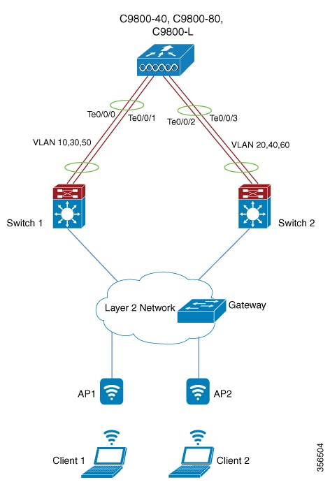
  • Provides the ability to distribute traffic on different uplinks, based on VLANs. For example, guest traffic can be completely isolated to a different switch or network from the enterprise network. You cannot configure the same VLAN on both uplinks.

Starting with Cisco IOS XE Amsterdam 17.2.1, the multichassis link aggregation group (multi-LAG) feature, which provides flexibility in connecting the controller to a switch's infrastructure, is supported.

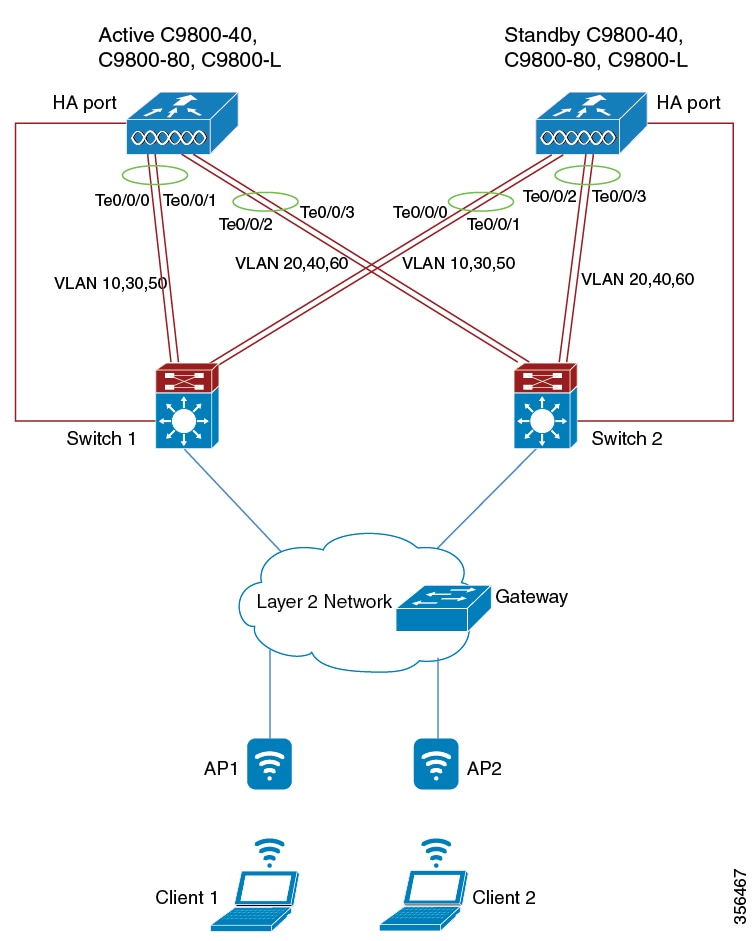
You can connect a LAG to a single switch. However, different VLANs is connected to different LAGs. The redundancy port is connected to the same distribution switch as the uplinks or directly connected in a back-to-back configuration.

Multi-LAG is supported in LAG ON mode, LACP, and PAgP modes.

Prerequisites for Multi-LAG

To ensure optimal performance and avoid configuration conflicts:

  • Connect each LAG to a single switch.

  • Assign different VLANs to different LAGs.

Restrictions for Multi-LAG

  • Automatic failover from the primary LAG to the secondary LAG is not supported if the primary LAG fails.

  • The interface on the controller does not come up when you shut or unshut the associated switch port.


    Note


    This restrictions is specific to Cisco Catalyst 9800-CL Cloud Wireless Controllers deployed in KVM environments using SR-IOV.


Supported topologies

Supported topologies are network deployment configurations. They define how Cisco Catalyst 9800 series controllers connect with the network through their available ports and set limitations regarding mixing port types and minimum group sizes for link aggregation.

The Cisco Catalyst 9800-80 Wireless Controller has eight ports, while the Cisco Catalyst 9800-40 and Cisco Catalyst 9800-L wireless controllers have four ports each. Multi-LAGs can only include ports with matching capabilities, such as 2.5 G with 2.5 G, or 10 G with 10 G ports. You cannot include both a 2.5 G port and a 10 G port in a port channel group. Each group must have a minimum of two ports in one LAG.

Figure 1. Single Controller with Multi-LAG
Figure 2. SSO Pair with Multi-LAG