Local area Bonjour for wireless FlexConnect mode
Local area Bonjour for wireless FlexConnect mode is a network service feature that
-
introduces unicast mode function in Local Area Bonjour network domain
-
enables enhanced gateway function at the first hop of Wired and Wireless networks to communicate directly with any industry standard RFC 6762 compliant Multicast DNS (mDNS) end point in Layer 2 Unicast mode, and
-
provides service-peer mode expanding single-gateway to end-to-end service-routing with upstream SDG-Agent switch to enable unicast-mode, increased scale, performance and resiliency in the network.
Restrictions for local area Bonjour for wireless FlexConnect mode
In FlexConnect mode network deployments, the mDNS gateway and service-peer mode on the controller must not be configured and must be in disabled state.
Prerequisites for local area Bonjour for wireless FlexConnect mode
The Cisco Catalyst 9800 series controller must be successfully configured and operational before implementing Cisco Local Area Bonjour for FlexConnect mode wireless networks.
Here are the prerequisites to enable successful mDNS gateway solution for Wireless FlexConnect:
-
Ensure that the targeted Layer 2 Catalyst 9000 Series Ethernet switch is configured in service-peer role and running the required Cisco IOS-XE software version.
-
Ensure that the Catalyst 9000 Series Ethernet switch runs a valid Cisco DNA-Advantage license.
-
Ensure that the upstream distribution-layer Cisco Catalyst switch for Wired and FlexConnect Local Switching Wireless networks is configured in SDG-Agent mode and runs a valid Cisco DNA-Advantage license.
mDNS gateway alternatives for wireless FlexConnect mode
mDNS gateway alternatives for wireless FlexConnect mode are implementation methods that
-
address evolving business and technical requirements in Enterprise networks
-
enable service discovery and distribution in FlexConnect Local Switching based wireless networks, and
-
provide two distinct approaches based on the operating network environment.
Implementation methods
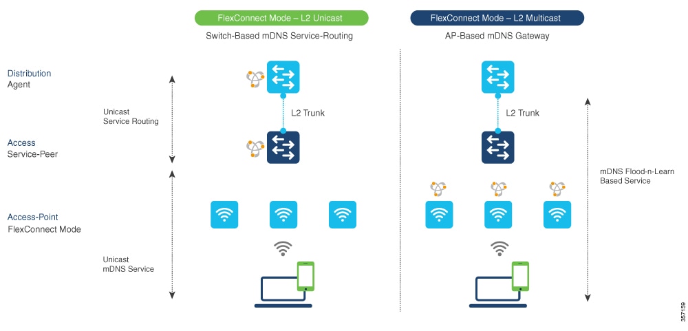
Based on the operating network environment, the mDNS gateway for FlexConnect mode wireless network can be implemented in one of the methods to address service discovery and distribution:
-
Switch Based mDNS Gateway—In Layer 2 access, the Cisco Catalyst 9000 series Ethernet switch must be implemented as mDNS gateway in Service-Peer role. The key benefits are:
-
Replaces flood-n-learn with the new enhanced Unicast-based mDNS communication with FlexConnect mode wireless users.
-
Eliminates mDNS flood with Unicast service-routing to LAN distribution. The Unicast service-routing between LAN distribution and Layer 2 access layer switches forms Local Area Bonjour domain to enable policy and location-based service discovery and distribution. The Unicast based service-routing over Layer 2 trunk eliminates mDNS flood-free and enables service-oriented wireless networks.
-
Eliminates the requirement to forward wired network traffic to wireless Access Points improving wireless scale, performance, and network reliability.
-
-
AP Based mDNS Gateway—The Cisco FlexConnect mode wireless access points can alternatively be implemented as mDNS gateway when connected to unsupported LAN access switch. In this method, the mDNS service discovery and distribution follows flood-n-learn mechanism over the Layer 2 wireless network. To implement AP based mDNS gateway, see the Multicast Domain Name System chapter.
Local area Bonjour for wireless FlexConnect mode
Local area Bonjour for wireless FlexConnect mode is a mDNS gateway function that
-
supports various advancements for broad range of wireless networks with distributed zero-configuration services
-
enables distributed Bonjour gateway function at network edge through common unified Cisco IOS-XE operating system across Cisco Catalyst 9000 series LAN switches and Cisco Catalyst 9800 series controller
-
provides end-to-end Wide Area Bonjour service-routing for service-oriented enterprise networks with intuitive user-experience.
mDNS gateway modes
The Cisco Catalyst 9000 series switches in the Layer 2 access layer and Layer 3 distribution layer must be configured in specific mDNS gateway modes to enable Unicast-based mDNS service-routing between wired and FlexConnect Local Switching mode wireless users within the same Layer 2 network block:
-
Service-Peer - The Layer 2 access switch connecting wireless access point in FlexConnect Local Switching mode must be configured with mDNS gateway in Service-Peer mode. Each Layer 2 access switch provides mDNS gateway function between locally attached wired and FlexConnect mode wireless users. The Unicast-based mDNS service discovery and distribution within same or different VLANs is supported with bi-directional mDNS policies on single Layer 2 access switch.
-
SDG Agent - The mDNS flood-n-learn based method in Layer 2 network is replaced with simple Unicast based service-routing between Layer 2 access switch in Service-Peer mode and upstream distribution-layer in mDNS gateway SDG Agent mode. The Unicast based mDNS service-routing eliminates mDNS flood over Layer 2 trunk ports providing increased bandwidth, enhanced security, location-based services, and flood control management in wired and FlexConnect wireless network.
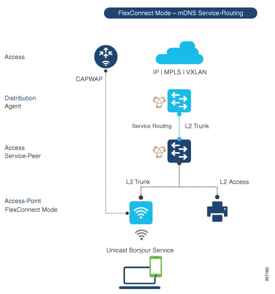
Controller mDNS gateway function architecture
This figure illustrates how the controller connected to wireless access points support mDNS gateway function to wireless users in FlexConnect Local Switching mode.
Local area Bonjour for wireless FlexConnect mode
Local area Bonjour for wireless FlexConnect mode is a network configuration that enables service discovery and routing across distributed wireless infrastructure by implementing Cisco Catalyst 9000 series Ethernet switches as mDNS gateways with service-peer and SDG Agent mode capabilities to build service-routing connections with upstream distribution-layer switches.
Configuration guidelines
This configuration enables service-peer and SDG Agent mode to enable service-routing with upstream distribution-layer Cisco Catalyst 9000 series switch in SDG Agent mode to build Local Area Bonjour.
Configure mDNS gateway mode (CLI)
This task enables mDNS gateway functionality on network switches to facilitate multicast DNS service discovery across network segments.
Use this procedure when you need to enable mDNS gateway and Service-Peer mode on Layer 2 access switch and SDG Agent mode on Layer 3 distribution layer switch.
Procedure
|
Step 1 |
enable Example:Enables privileged EXEC mode. Enter your password, if prompted. |
||
|
Step 2 |
configure terminal Example:Enters global configuration mode. |
||
|
Step 3 |
mdns-sd gateway Example:Enables mDNS on the Layer 2 Catalyst switch and enters the mDNS gateway configuration mode. (Optional) You can configure additional parameters:
|
||
|
Step 4 |
mode {service-peer | SDG-agent} Example:Configure mDNS gateway in one of these modes based on the system settings:
|
||
|
Step 5 |
exit Example:Exits mDNS gateway configuration mode. |
The mDNS gateway mode is configured on the switch. The switch can now facilitate mDNS service discovery across network segments based on the configured mode.
Configure mDNS service policy (CLI)
Configure mDNS service policy to enable multicast DNS service discovery and proxy functionality on Catalyst switches, allowing service advertisement and discovery across VLANs in both Service-Peer and SDG agent modes.
You need to perform this configuration to enable mDNS service policy on Catalyst switches. This configuration is required in Service-Peer mode for Layer 2 Catalyst switches and SDG agent mode for Layer 3 Catalyst switches.
You need to perform the following to configure an mDNS service policy:
-
Create service-list to permit built-in or user-defined custom service types.
-
Associate service-list to a service-policy to enforce ingress or egress direction.
-
Apply the service policy to the new VLAN configuration mode.
 Note |
You will need this configuration in Service-Peer mode for Layer 2 Catalyst switch and SDG agent mode for Layer 3 Catalyst switch. |
The figure shows how to configure mDNS policies on Catalyst switch in Service-Peer and SDG agent modes.
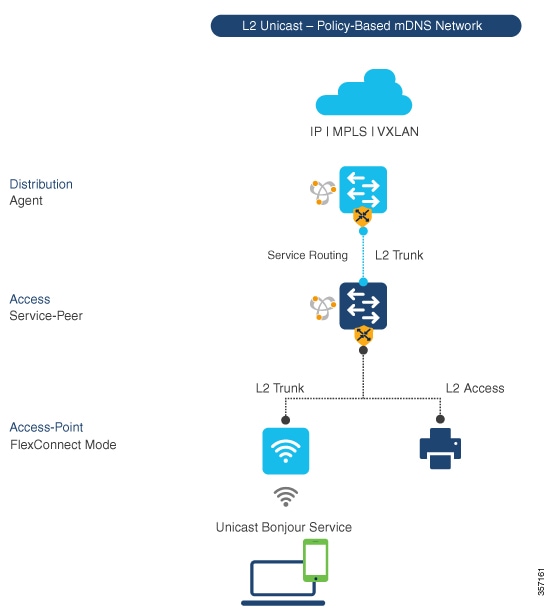
This procedure builds and applies service-policies on target VLAN in service-peer and SDG agent modes.
Before you begin
Follow these steps to configure mDNS service policy using CLI commands:
Procedure
|
Step 1 |
enable Example:Enables privileged EXEC mode. Enter your password, if prompted. |
|
Step 2 |
configure terminal Example:Enters global configuration mode. |
|
Step 3 |
mdns-sd service-list service-list-name {in | out} Example:Configure mDNS service-list to classify one or more service types. Unique service-list is required to process incoming mDNS message and outbound response to request locally connected wired or FlexConnect wireless end points. |
|
Step 4 |
match service-definition-name [message-type {any | announcement | query}] Example:Matches inbound service-list. The Catalyst switch validates to accept or drop incoming mDNS service-type (such as, Apple TV) advertisement or query matching message type from locally connected wired or FlexConnect wireless end points. The service-list contains implicit deny at the end. The default message-type used is any. |
|
Step 5 |
match service-definition-name [message-type {any | announcement | query}] Example:Matches outbound service-list. The Catalyst switch provides local service proxy function by responding matching service-type to the requesting end point(s). For example, the Apple-TV and Printer learnt from VLAN 100 will be distributed to FlexConnect wireless receiver in same VLAN 100. The service-list contains implicit deny at the end. The message-type for outbound service-list is not required. |
|
Step 6 |
mdns-sd service-policy service-policy-name Example:Creates unique mDNS service-policy in global configuration mode. |
|
Step 7 |
service-list service-list-name {in | out} Example:Configures mDNS service-policy to associate service-list for each direction. |
|
Step 8 |
VLAN configuration ID Example:Enables wired or wireless FlexConnect user VLAN configuration for advanced service parameters. One or more VLANs can be created for the same settings. Here, ID refers to the VLAN configuration ID. The range is from 101 to 110 and 200. This range allows to configure consecutive and non-consecutive VLAN ID(s). |
|
Step 9 |
mdns-sd gateway Example:Enables mDNS gateway on configured wired or FlexConnect wireless user VLAN ID(s). |
|
Step 10 |
service-policy service-policy-name Example:Associates mDNS service-policy to the configured wired or FlexConnect wireless user VLAN ID(s). |
|
Step 11 |
exit Example:Exits mDNS gateway configuration mode. |
The mDNS service policy is successfully configured and applied to the specified VLAN. The Catalyst switch can now process mDNS service advertisements and queries according to the configured service lists and policy rules.
Configure mDNS Location-Filter (CLI)
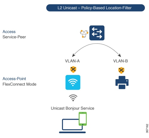
Configure mDNS location-filter to enable local service proxy on Cisco Catalyst switch in Service-Peer mode and discover mDNS services between local wired and wireless FlexConnect user VLANs.
Optionally, you can configure mDNS location-filter to allow service discovery and distribution between locally configured VLAN IDs associated to FlexConnect wireless user networks.
The following figure illustrates and references location-filter policy on Catalyst switch in Service-Peer mode permitting to discover and distribute mDNS services between wired and FlexConnect wireless user VLANs.
Before you begin
Follow these steps to enable local service proxy on Cisco Catalyst switch in Service-Peer mode and discover mDNS services between local wired and wireless FlexConnect user VLANs:
Procedure
|
Step 1 |
enable Example:Enables privileged EXEC mode. Enter your password, if prompted. |
||
|
Step 2 |
configure terminal Example:Enters global configuration mode. |
||
|
Step 3 |
mdns-sd location-filter location-filter-name Example:Configures a unique location-filter in global configuration mode. |
||
|
Step 4 |
match location-group {all | default | ID} VLAN [ID] Example:Configures the match criteria to mutually distribute the permitted services between grouped VLANs. For example, mDNS services can be discovered and distributed using the Unicast mode between wireless FlexConnect user VLAN ID 100 and wired user VLAN ID 101. |
||
|
Step 5 |
mdns-sd service-list service-list-name {in | out} Example:Configures the mDNS service-list to classify one or more service types. The service-list configuration is required to process any incoming or outgoing mDNS messages. |
||
|
Step 6 |
match service-definition-name [message-type {any | announcement | query}] Example:Associates location-filter to one or more service types to enable local proxy between local VLANs. For example, the Apple-TV learnt from VLAN 100 and VLAN 101 will be distributed to receiver in VLAN 100.
|
||
|
Step 7 |
mdns-sd service-policy service-policy-name Example:Creates unique mDNS service-policy in global configuration mode. |
||
|
Step 8 |
service-list service-list-name {in | out} Example:Configures mDNS service-policy to associate service-list for each direction. |
||
|
Step 9 |
VLAN configuration ID Example:Enables VLAN configuration for advanced service parameters. You can create one or more VLANs with the same settings. Here, ID refers to the VLAN configuration ID. The range is from 101 to 110 and 200. This range allows to configure consecutive and non-consecutive VLAN ID(s). |
||
|
Step 10 |
mdns-sd gateway Example:Enables mDNS gateway on configured VLAN ID(s). |
||
|
Step 11 |
service-policy service-policy-name Example:Associates mDNS service-policy to the configured VLAN ID(s). |
||
|
Step 12 |
exit Example:Exits mDNS gateway configuration mode. |
mDNS location-filter is successfully configured to enable local service proxy between the specified VLANs. The mDNS services can now be discovered and distributed between wired and FlexConnect wireless user VLANs.
Configure custom service definition (CLI)
Create custom service-definition with matching mDNS PTR records to enable end mDNS service-routing in the network.
The Cisco IOS-XE supports mapping of various built-in well-known mDNS service-definition types to key mDNS PTR records and user-friendly names. For example, built-in Apple-TV service-type is associated with _airplay. _tcp.local and _raop. _tcp.local PTR records to successfully enable service in the network. Network administrators create custom service-definition with matching mDNS PTR records to enable end mDNS service-routing in the network.
Procedure
|
Step 1 |
enable Example:Enables privileged EXEC mode. Enter your password, if prompted. |
|
Step 2 |
configure terminal Example:Enters global configuration mode. |
|
Step 3 |
mdns-sd service-definition service-definition-name Example:Creates a unique service-definition name for custom service-types. |
|
Step 4 |
service-type custom-mDNS-PTR Example:Configures a regular-expression string for custom mDNS PoinTeR(PTR) record. |
|
Step 5 |
exit Example:Exits mDNS gateway configuration mode. |
The custom service-definition is configured and can be associated to the service-list to enable mDNS service-routing functionality in the network.
Configure service-routing on service-peer using CLI
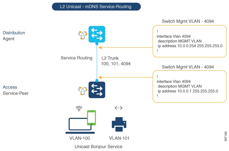
Configure service-routing on a Layer 2 Cisco Catalyst switch in Service-Peer mode to establish communication with an upstream distribution-layer switch in SDG Agent mode and enable mDNS trust interface settings.
The Layer 2 Cisco Catalyst switch in Service-Peer mode builds a service-routing with an upstream distribution-layer switch in the SDG Agent mode. To build service-routing, the Layer 2 Cisco Catalyst switch requires at least one interface with valid IP address to reach the upstream SDG Agent Catalyst switch. The switch management port is unsupported.
The following figure illustrates the topology to enable unicast-based service-routing over Layer 2 trunk between access-layer Catalyst switch in the Service-Peer mode and distribution-layer Catalyst switch in SDG Agent mode.
Before you begin
Follow these steps to configure service-routing on Cisco Catalyst switch in Service-Peer mode and setup mDNS trust interface settings:
Procedure
|
Step 1 |
enable Example:Enables Privileged EXEC mode. Enter your password, if prompted. |
|
Step 2 |
configure terminal Example:Enters the global configuration mode. |
|
Step 3 |
VLAN configuration ID Example:Enables Wired and FlexConnect user VLAN configuration for advanced service parameters. One or more VLANs can be created for the same settings. Here, ID refers to the VLAN configuration ID. For example, VLAN configuration 101-110, 200 range, allows to configure consecutive and non-consecutive VLAN ID(s). |
|
Step 4 |
mdns-sd gateway Example:Enables mDNS gateway on configured VLAN ID(s). To enable the respective functionalities, enter these commands in the mDNS gateway configuration mode:
|
|
Step 5 |
source-interface ID Example:Selects the interface with a valid IP address to source service-routing session with the upstream Cisco Catalyst SDG Agent switch. Typically, the management VLAN interface can be used. |
|
Step 6 |
SDG-agent [IPv4_address] Example:Configures the SDG Agent IPv4 address, typically, the management VLAN gateway address. If FHRP mode, then use the FHRP virtual IP address of the management VLAN. |
|
Step 7 |
exit Example:Exits the mDNS gateway configuration mode. |
Service-routing is configured on the service-peer, establishing communication with the upstream SDG Agent switch and enabling mDNS gateway functionality on the specified VLAN.
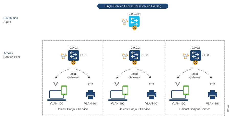
Location-based mDNS
Location-based mDNS is a network service discovery mechanism that
-
enables per-switch mDNS discovery and distribution for FlexConnect wireless users attached locally to Layer 2 Catalyst switches in Service-Peer mode by default
-
supports user mobility across multiple Layer 2 Catalyst switches even when FlexConnect user VLANs are extended between switches, and
-
requires mDNS service-policy configuration on the SDG Agent to accept policy-based service provider and receiver information from downstream Service-Peer access-layer switches.
Per-switch location-based FlexConnect configuration
The following figure shows the per-switch location-based FlexConnect configuration topology.
Note |
Configure the mDNS service policy on the distribution layer SDG Agent switch before proceeding to the next configuration step. For more information, see the Configuring mDNS Service Policy section. |
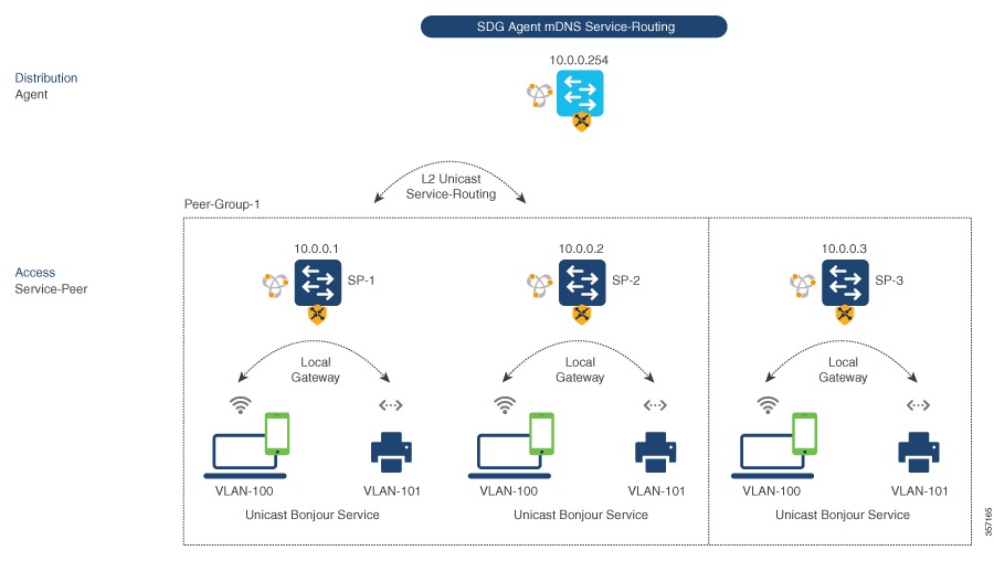
Configure service-routing on SDG agent (CLI)
Configure service-routing on SDG agent to enable Unicast mode Bonjour service-routing with downstream Layer 2 access-layer Ethernet switches connected to FlexConnect wireless users.
The Cisco Catalyst 9000 series switches support SDG Agent mode automatically at the distribution layer and enables Unicast mode Bonjour service-routing with the downstream Layer 2 access-layer Ethernet switches connected to the FlexConnect wireless users. The SDG Agent must be configured with mDNS service-policy on wireless FlexConnect user VLAN to accept mDNS service cache from downstream Service-Peer switches.
This section provides step-by-step configuration guidelines to enable policy-based service discovery and distribution between locally paired Layer 2 access network switches in the Service-Peer mode.
The following figure illustrates unicast service-routing on SDG Agent and downstream Layer 2 access network switches in the Service-Peer mode.
Before you begin
Note |
Configure the mDNS service policy on the distribution layer SDG Agent switch before proceeding to the next configuration step. For more information, see the Configuring mDNS Service Policy section. |
Follow these steps to enable the mDNS service policy and peer-group on SDG Agent switch, and enable Unicast mode service-routing with Layer 2 access network switches in Service-Peer mode:
Procedure
|
Step 1 |
enable Example:Enables privileged EXEC mode. Enter your password, if prompted. |
|
Step 2 |
configure terminal Example:Enters global configuration mode. |
|
Step 3 |
mdns-sd service-peer group service-peer-group-name Example:Configures a unique Service-Peer group. |
|
Step 4 |
peer-group [ID] Example:Assigns a unique peer-group ID to the Service-Peers pair permitting mDNS service discovery and distribution within the assigned group list. The valid peer-group range is from 1 to 1000 for each SDG Agent switch. |
|
Step 5 |
service-policy service-policy-name Example:Associates an mDNS service policy to accept service advertisements and query from the paired Service-Peers. |
|
Step 6 |
service-peer [IPv4_address] location-group {all | default | ID} Example:Configures at least one Service-Peer to accept the mDNS service advertisement or query message. When a group has more than one Service-Peers, the SDG Agent provides Layer 2 Unicast mode routing between the configured peers. For example, the SDG Agent provides Unicast based service gateway function between three (10.0.0.1 and 10.0.0.2) Layer 2 Service-Peer switches matching the associated service-policy. The mDNS service information from the unpaired Layer 2 Service-Peer (10.0.0.3) cannot announce or receive mDNS services with the other grouped Service-Peers (10.0.0.1 and 10.0.0.2). |
|
Step 7 |
exit Example:Exits mDNS gateway configuration mode. |
The SDG Agent is configured with service-routing to enable Unicast mode service-routing with downstream Layer 2 access network switches in Service-Peer mode.
Verify local area Bonjour in service-peer mode
This section provides guidelines to verify various Local Area Bonjour domain mDNS service configuration parameters, cache records, statistics and more on the controller in service-peer mode.
|
Command or Action |
Purpose |
||
|---|---|---|---|
|
show mdns-sd cache {all | interface | MAC | name | service-peer | static | type | VLAN} |
Displays available mDNS cache records supporting multiple variables providing granular source details received from wired or wireless FlexConnect user VLANs. The variables are as follows:
|
||
|
show mdns-sd service-definition {name | type} |
Displays built-in and user-defined custom service-definition that maps service name to the mDNS PTR records. The service-definition can be filtered by name or type. |
||
|
show mdns-sd service-list {direction | name} |
Displays inbound or outbound direction list of configured service-list to classify matching service-types for service-policy. The list can be filtered by name or specific direction. |
||
|
show mdns-sd service-policy {interface | name} |
Displays list of mDNS service-policy mapped with inbound or outbound service-list. The service-policy list can be filtered by an associated specified interface or name. |
||
|
show mdns-sd statistics {all | cache | debug | interface | service-list | service-policy | services | VLAN} |
Displays detailed mDNS statistics processed bi-directionally by the system on each mDNS gateway enabled VLAN configured mDNS in Unicast mode. The expanded keyword for mDNS statistics can provide detailed view on interface, policy, service-list, and services.
|
||
|
show mdns-sd summary {interface | VLAN} |
Displays brief information about mDNS gateway and key configuration status on all wired and wireless FlexConnect user VLANs, and interfaces of the system. |
Verify local area Bonjour in SDG agent mode
This section provides guidelines to verify various Local Area Bonjour domain mDNS service configuration parameters, cache records, statistics and more on the controller in SDG Agent mode
|
Command or Action |
Purpose |
|---|---|
|
show mdns-sd cache {all | interface | MAC | name | service-peer | static | type | VLAN | VRF} |
Displays available mDNS cache records supporting multiple variables providing granular source details. The variables are as follows:
|
|
show mdns-sd service-definition {name | type} |
Displays built-in and user-defined custom service-definition that maps service name to the mDNS PTR records. The service-definition can be filtered by name or type. |
|
show mdns-sd service-list {direction | name} |
Displays inbound or outbound direction list of the configured service-list to classify matching service-types for service-policy. The list can be filtered by name or specific direction. |
|
show mdns-sd service-policy {interface | name} |
Displays list of mDNS service-policy mapped with inbound or outbound service-list. The service-policy list can be filtered by an associated specified interface or name. |
|
show mdns-sd statistics {all | cache | debug | interface | service-list | service-policy | services | VLAN} |
Displays detailed mDNS statistics processed bi-directionally by the system on each mDNS gateway enabled VLAN configured mDNS in Unicast mode. The expanded keyword for mDNS statistics can provide detailed view on interface, policy, service-list, and services. |
|
show mdns-sd summary {interface | VLAN} |
Displays brief information about mDNS gateway and key configuration status on all VLANs and interfaces of the system. |
Reference
|
Related Topic |
Document Title |
|---|---|
|
DNA Service for Bonjour Deployment on Cisco Catalyst 9600 Switch |
Cisco Catalyst 9600 Series Switch Software Configuration Guide, Release 17.5.X |
|
DNA Service for Bonjour Deployment on Cisco Catalyst 9500 Switch |
Cisco Catalyst 9500 Series Switch Software Configuration Guide, Release 17.5.X |
|
DNA Service for Bonjour Deployment on Cisco Catalyst 9400 Switch |
Cisco Catalyst 9400 Series Switch Software Configuration Guide, Release 17.5.X |
|
DNA Service for Bonjour Deployment on Cisco Catalyst 9300 Switch |
Cisco Catalyst 9300 Series Switch Software Configuration Guide, Release 17.5.X |
|
Cisco Wide Area Bonjour Application on Cisco Catalyst Center User Guide |
Cisco Wide Area Bonjour Application on Cisco Catalyst Center User Guide, Release 2.2.2 |
 Feedback