|
Start the Side B Unified
CVP components
|
|
1.
|
Start
Unified CVP Server 1B and then start the Unified CVP Reporting Server.
| Note
|
You do
not need to start Unified CVP Server 2B as it is removed during the migration.
|
|
|
Upgrade the Side B Unified
CVP Servers
|
|
2.
|
Update
the settings on the Unified CVP Server 1B VM.
See
Update VMware Settings for the Unified CVP Server.
|
|
3.
|
Upgrade
Unified CVP Server 1B.
See
Upgrade the Unified CVP Server.
|
|
4.
|
Remove the
Unified CVP Server 2B VM.
| Note
|
Delete the Call Server, Media Server, and VXML Server from
the Unified CVP OAMP Server before removing the Unified CVP Server 2B VM.
|
|
|
5.
|
Update the
Cisco IOS Enterprise Ingress Voice Gateway dial-peer configuration to remove
Unified CVP Server 2B.
|
|
6.
|
Obtain and
transfer the license now if you don't have an on-box Unified CVP Reporting
Server.
If you
have an on-box Unified CVP Reporting Server, you can transfer the upgrade
license to all Unified CVP components after you upgrade the Unified CVP
Reporting Server.
See
Obtain and Transfer the Upgrade License for Unified CVP.
|
|
Upgrade the on-box Unified
CVP Reporting Server (if used)
|
|
7.
|
Complete
the Unified CVP Reporting Server preupgrade tasks.
See
Unified CVP Reporting Server Preupgrade Tasks.
|
|
8.
|
Unload
the data from the Unified CVP Reporting Server.
See
Unload Data From Reporting Database.
|
|
9.
|
Uninstall the Unified CVP Reporting Server.
See
Uninstall the Unified CVP Component from the Reporting Server VM.
|
|
10.
|
Update
the settings on the Unified CVP Reporting Server VM.
See
Update VMware Settings for the Unified CVP Reporting Server.
|
|
11.
|
Install
the Unified CVP Reporting Server.
See
Install Cisco Unified CVP Reporting Server.
|
|
12
|
Load data on the Unified CVP Reporting Server.
See Load Data to Reporting Server Database.
|
|
13.
|
Save and
deploy the Unified CVP Reporting Server in the Operations Console.
See
Save and Deploy the Unified CVP Reporting Server.
|
|
14.
|
Transfer
the upgrade license.
See
Obtain and Transfer the Upgrade License for Unified CVP.
|
|
Upgrade Side B Cisco Voice
Gateway IOS Version if needed
|
|
15.
|
Upgrade
the Side B Cisco Voice Gateway IOS version to the minimum required by the
upgraded
Packaged CCE release
(or later).
See
Upgrade Cisco Voice Gateway IOS Version.
See the Cisco Packaged CCE Software Compatibility Matrix at https://www.cisco.com/c/en/us/support/customer-collaboration/packaged-contact-center-enterprise/products-device-support-tables-list.html for IOS support information.
|
|
Upgrade the Side B Finesse
and Unified Intelligence Center VMs
|
|
16.
|
Power on
the Finesse Secondary node VM in the vSphere client.
|
|
17.
|
Upgrade the VMware version on the Finesse Secondary VM.
See Upgrade the Virtual Machine Hardware Version.
|
|
18.
|
Update
the settings on the Finesse Secondary VM.
See
Update VMware Settings for Cisco Finesse.
|
|
19.
|
Upgrade
the Finesse Secondary node.
See
either:
|
|
20.
|
Power on
the Unified Intelligence Center Subscriber VM in the vSphere client.
|
|
21.
|
Upgrade the VMware version on the Unified Intelligence Center Subscriber VM.
See Upgrade the Virtual Machine Hardware Version.
|
|
22.
|
Update
the settings on the Unified Intelligence Center Subscriber VM.
See
Update VMware Settings for Cisco Unified Intelligence Center.
|
|
23.
|
Upgrade
the Unified Intelligence Center Subscriber.
See
either:
| Note
|
Your
configuration information migrates automatically to the upgraded version in the
active partition.
|
|
|
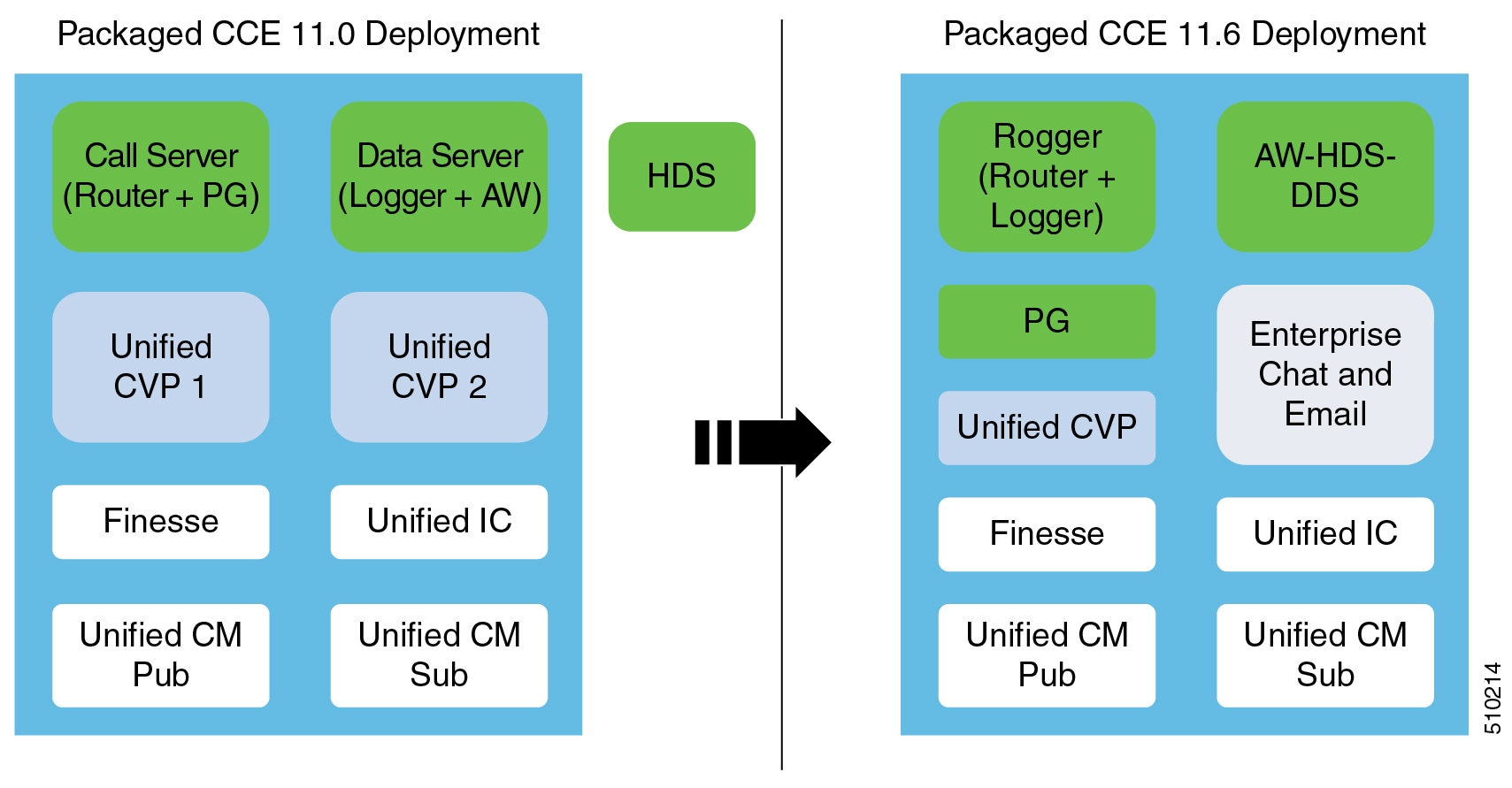
Prepare for Side B
Migration to
Packaged CCE 2000 Agent
Rogger Deployment
|
|
24.
|
Back up
and export the Side B SQL database.
See
Back Up Database.
|
|
Install the Side B
Unified CCE Rogger
|
|
25.
|
Create a
VM for the Side B Unified CCE Rogger.
Using
Packaged-CCE-UCCE.ova,
Create a Virtual Machine from the OVA.
Select
CCE Rogger from the drop-down list.
|
|
26.
|
Install
Microsoft Windows Server on the Side B Unified CCE Rogger VM.
See
Install Microsoft Windows Server.
|
|
27.
|
Install
VMware tools on the Side B Unified CCE Rogger VM.
See
Install VMware Tools.
|
|
28.
|
Configure the network adaptors for the Side B Unified CCE
Rogger.
See
Configure Network Adapters for Unified CCE Rogger and Unified CCE PG
.
|
|
29.
|
Install
antivirus software on the Side B Unified CCE Rogger.
See
Install Antivirus Software.
|
|
30.
|
Configure the database drive for the Side B Unified CCE Rogger.
See
Configure Database Drive.
|
|
31.
|
Set
persistent static routes.
See
Set Persistent Static Routes.
|
|
32.
|
Run
Windows updates.
See
Run Windows Updates.
|
|
33.
|
Add the
Unified CCE Rogger to the domain.
|
|
34.
|
Install
Microsoft SQL Server.
Install Microsoft SQL Server.
|
|
35.
|
Install
Cisco Unified Contact Center Enterprise.
See
Install Cisco Unified Contact Center Enterprise.
|
|
Configure the Side B
Unified CCE Rogger
|
|
36.
|
Add a
UCCE Instance in Web Setup.
See
Add a UCCE Instance.
|
|
37.
|
Configure SQL Server for the Logger database.
See
Configure SQL Server for CCE Components.
|
|
38.
|
Configure the Logger database and log.
See
Configure the Logger Database and Log.
|
|
39.
|
Import
the Side B SQL database that you previously backed up in step 24.
| Note
|
Do not
import the Outbound database to Side B.
|
|
|
40.
|
Add a
Unified CCE Router component in Web Setup.
See
Add a Unified CCE Router Component.
|
|
41.
|
Add a
Unified CCE Logger component in Web Setup.
See
Add a Unified CCE Logger Component.
|
|
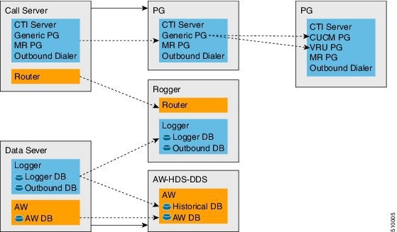
Convert the Side B
Unified CCE Data Server and Unified CCE Call Server
|
|
42.
|
Upgrade the VMware version on the Side B Data Server VM.
See Upgrade the Virtual Machine Hardware Version.
|
|
43.
|
Update
the settings on the Side B Data Server VM.
See
Update VMware Settings on the Unified CCE Data Server.
|
|
44.
|
Convert
the Side B Unified CCE Data Server to a Unified CCE AW-HDS-DDS.
See
Convert Unified CCE Data Server to Unified CCE AW-HDS-DDS.
|
|
45.
|
Update
the real-time and historical datasources for Unified Intelligence Center to
point to the Unified CCE AW-HDS-DDS.
You must update the historical data source database name to <instancename>_awdb.
|
|
46.
|
Upgrade the VMware version on the Side B Call Server VM.
See Upgrade the Virtual Machine Hardware Version.
|
|
47.
|
Update
the settings on the Side B Call Server VM.
See
Update VMware Settings on the Unified CCE Call Server.
|
|
48.
|
Remove
the Router from the Side B Unified CCE Call Server.
See
Remove the Router from the Unified CCE Call Server.
| Note
|
If CTI
OS Server is present, remove it as well. CTI OS is no longer supported.
|
The Call
Server is now a PG.
|
|
49.
|
Run the Unified CCE 11.6(1) installer on the Side B Unified CCE Rogger to upgrade to Release 11.6(1).
See Install Cisco Unified Contact Center Enterprise Release 11.6(1).
|
|
50.
|
Disable
configuration changes on the Side B Unified CCE Rogger. Change the following
registry key to 1:
HKEY_LOCAL_MACHINE\SOFTWARE\Cisco Systems, Inc.\ICM\<instance
name>\RouterB\Router\CurrentVersion\Configuration\Global\DBMaintenance
|
|
51.
|
Run the Unified CCE
11.6(1) installer on the Side B Unified CCE AW-HDS-DDS (former Data Server) to
upgrade to Release 11.6(1).
See Install Cisco Unified Contact Center Enterprise Release 11.6(1).
|
|
52.
|
Run the Unified CCE 11.6(1) installer on the Side B PG (former Call Server) to upgrade to Release 11.6(1).
See Install Cisco Unified Contact Center Enterprise Release 11.6(1).
|
|
53.
|
Modify
the Side B PG to point to the Unified CCE Rogger.
See
Modify the PG.
|
|
54.
|
Modify
the dialer to point to the Unified CCE Rogger (if using Outbound Option).
See
Modify the Dialer.
|
|
Optional: Upgrade the
External HDS associated with Side B (if used)
|
|
55.
|
Upgrade the VMware version on the External HDS associated with Side B.
See Upgrade the Virtual Machine Hardware Version.
|
|
56.
|
Run the Unified CCE 11.6(1) installer on the External HDS associated with Side B to upgrade to Release 11.6(1).
See Install Cisco Unified Contact Center Enterprise Release 11.6(1).
|
|
57.
|
Update
the Central Controller connectivity to point to the Unified CCE Rogger.
See
Update the Central Controller Connectivity.
|
|
Optional: Install
language pack
|
|
58.
|
Install
the language pack on the Side B Unified CCE Rogger, AW-HDS-DDS, PG (formerly
Call Server), and External HDS (if used).
See
Install the Language Pack.
|
|
Upgrade Side B Unified
Communications Manager Subscriber 2
|
|
59.
|
Power on
the Unified Communications Manager Subscriber 2 VM in the vSphere client.
|
|
60.
|
Upgrade
the Side B Unified Communications Manager Subscriber 2.
See
either:
|
|
61.
|
Upgrade
JTAPI on the Side B PG (formerly Call Server).
See
Upgrade JTAPI on the PG.
|
|
Optional: Change
hostnames of the Unified CCE components
|
|
62.
|
Optional: Change the hostnames of the Unified CCE components
(AW-HDS-DDS and PG).
| Note
|
You
can perform this task when you reboot each component as part of the upgrade. If
you do change the hostnames, you must also change them in the following places:
-
Finesse
-
PG
Setup
-
Unified Intelligence Center - Historical and real-time
-
Private network DNS entries
-
Live Data—If you change the hostname of the AW-HDS-DDS (former
Data Server), Live Data no longer connects to the AW-HDS-DDS after the Data
Server hostname is removed from DNS. To fix this, do the following:
-
Run the following CLI command on the CUIC-LD-IdS Publisher:
unset live-data aw-access secondary
-
Restart Cisco Tomcat on the Side B AW-HDS-DDS.
|
|

 Feedback