Installation Prerequisites
To install the Cisco UCS XE150c M8 Compute Node, be aware of the following prerequisites.
 Note |
For indoor use only. Connect PoE ports only to PoE networks that are not routed to outside plant. Per IEC TR 62101, PoE is considered Network Environment 0; interconnected ITE circuits may therefore be considered SELV. |
General Safety Warnings
Take note of the following general safety warnings.
 Warning |
IMPORTANT SAFETY INSTRUCTIONS Before you work on any equipment, be aware of the hazards involved with electrical circuitry and be familiar with standard practices for preventing accidents. Read the installation instructions before using, installing, or connecting the system to the power source. Use the statement number at the beginning of each warning statement to locate its translation in the translated safety warnings for this device. SAVE THESE INSTRUCTIONS  |
Note |
You are strongly advised to read the safety instruction before using the product. https://www.cisco.com/web/JP/techdoc/pldoc/pldoc.html When installing the product, use the provided or designated connection cables/power cables/AC adapters. 〈製品使用における安全上の注意〉 www.cisco.com/web/JP/techdoc/index.html 接続ケーブル、電源コードセット、ACアダプタ、バッテリなどの部品は、必ず添付品または 指定品をご使用ください。添付品・指定品以外をご使用になると故障や動作不良、火災の 原因となります。また、電源コードセットは弊社が指定する製品以外の電気機器には使用 できないためご注意ください。 |
Warning |
To reduce risk of electric shock or fire, installation of the equipment must comply with local and national electrical codes. |
Note |
An instructed person is someone who has been instructed and trained by a skilled person and takes the necessary precautions when working with equipment. A skilled person or qualified personnel is someone who has training or experience in the equipment technology and understands potential hazards when working with equipment. |
Warning |
Ultimate disposal of this product should be handled according to all national laws and regulations. |
Equipment Installation to Power Warnings
Take note of the following power safety warnings.
Warning |
To reduce risk of electric shock or personal injury, disconnect DC power before removing or replacing components or performing upgrades. |
Warning |
This unit is intended for installation in restricted access areas. Only skilled, instructed, or qualified personnel can access a restricted access area. |
Warning |
To reduce the risk of electric shock and fire, a readily accessible disconnect device must be incorporated in the fixed wiring. |
Warning |
To reduce risk of electric shock, when installing or replacing the unit, the ground connection must always be made first and disconnected last. If your unit has modules, secure them with the provided screws. |
Ground Connection Warnings
Take note of the following ground connection warnings.
Warning |
This equipment must be grounded. To reduce the risk of electric shock, never defeat the ground conductor or operate the equipment in the absence of a suitably installed ground conductor. Contact the appropriate electrical inspection authority or an electrician if you are uncertain that suitable grounding is available. |
Warning |
In the Scandinavian countries (Denmark, Finland, Iceland, Norway, and Sweden) the appliance must be connected to a grounded outlet. |
Optical Connection Warnings
Take note of the following optical connection warnings.
Warning |
Invisible laser radiation may be emitted from disconnected fibers or connectors. Do not stare into beams or view directly with optical instruments. |
Warning |
Invisible laser radiation is present. Do not expose to users of telescopic optics. This applies to Class 1/1M laser products. 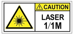 |
Warning |
Laser Safety: Ensure all unused ports are capped to maintain eye safety and prevent signal contamination. |
General Node and Component Replacement Warnings
Take note of the following component replacement warning.
Warning |
Electrostatic Discharge (ESD): The Cisco UCS XE150c M8 Compute Node contains high-density integrated circuits. Always utilize an ESD-preventive wrist strap during handling to avoid permanent hardware damage. |
Additional Information
The Cisco UCS XE150c M8 Compute Node installs into the Cisco UCS XE9305 Chassis. Installation information for the compute node is contained in this installation and service guide. However, to get complete information about the compute node and the chassis that contains it, consult the following documents.
|
Document |
Topics |
Link |
|---|---|---|
|
Cisco Unified Edge XE9305 Chassis Installation and Service Guide |
Cisco Unified Edge XE9305 Chassis Installation and Service Guide |
|
|
Regulatory Compliance and Safety Information (downloadable PDF) |
-- |
Regulatory Compliance and Safety Information – Cisco UCS XE9305 Modular System |

 Feedback
