Installing the Chassis

This chapter contains the following topics:

Product Transportation and Handling Considerations

Be aware of the following transporting and safe handling requirements for this product:

  • Although not a requirement, it is a best practice to secure the product into a shipping container, such as the original packaging that came with the product.

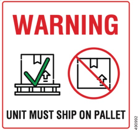
  • Whenever the product is shipped or transported, it is a requirement that the product is loaded onto a pallet.


    Caution


    Before loading the product onto a pallet, inspect the pallet for damage, missing screws, nails, or other fasteners. Only use undamaged pallets that are not missing any fasteners to ship the product.


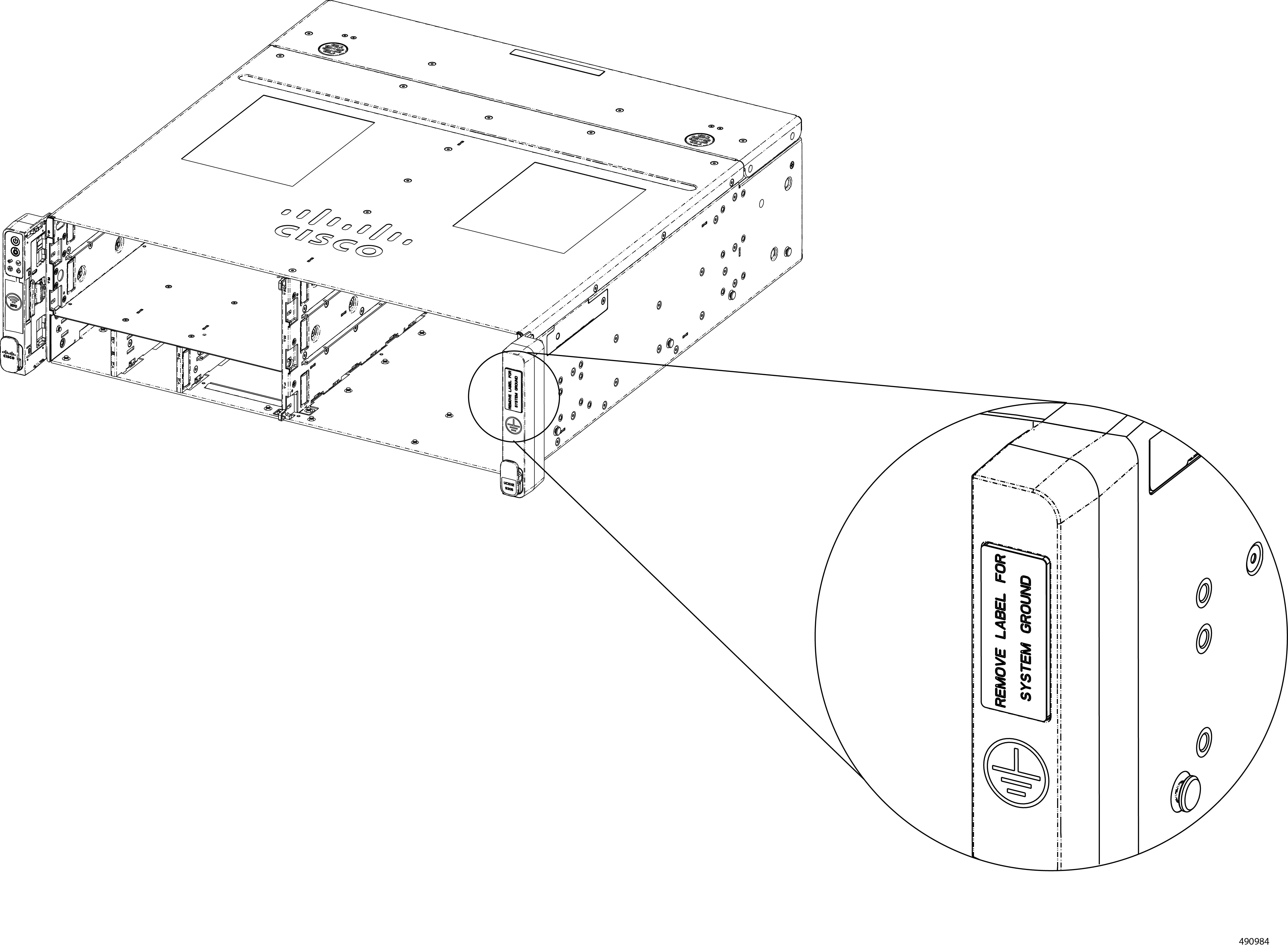
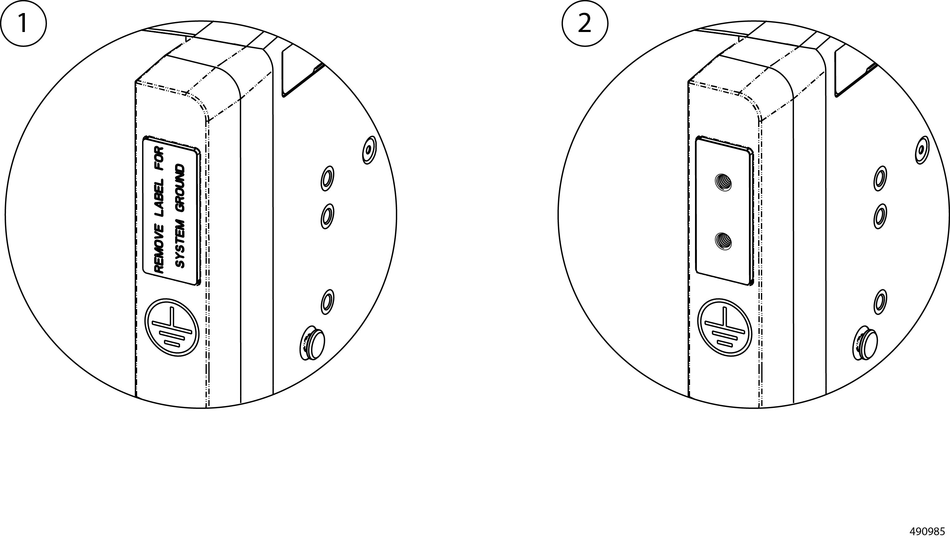
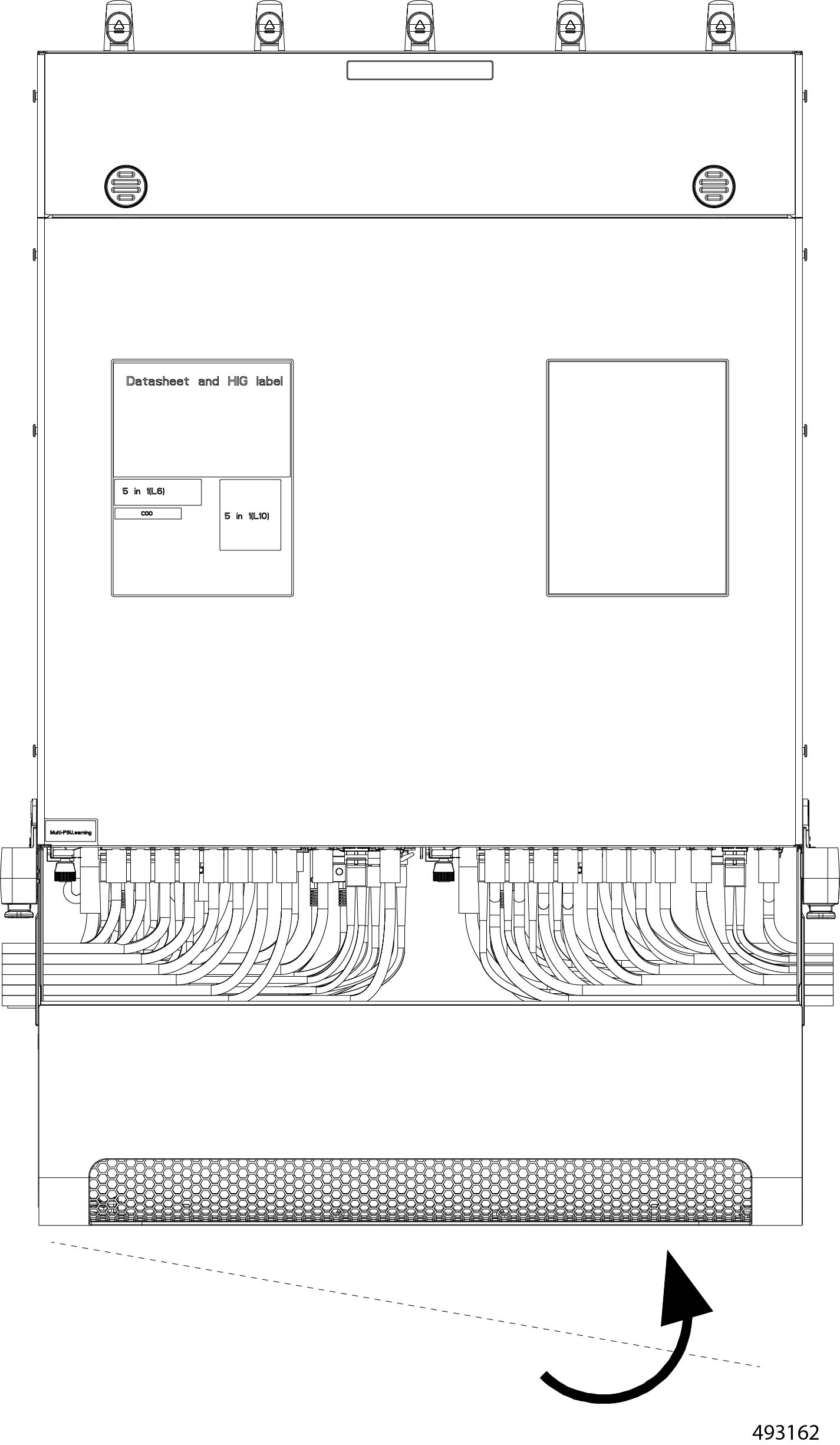
    This requirement is also indicated by the following label which is directly affixed to the product.

You must use these transportation and handling considerations for shipping or transporting the product to or from any customer or order fulfillment site, or when return shipping the product to Cisco Systems, for example, due to an RMA.

If you do not have access to a pallet that can support the product's weight and size, you can order one from Cisco Systems by ordering UCSXE-PKG-MINIPLT=


Note


The Cisco pallet (UCSXE-PKG-MINIPLT=) does not include any product packaging or shipping container.


Caution


Shipping the product without using an appropriate pallet can void your product warranty.


Safety Warnings

This topic contains safety warnings for the installation and use of the product. Additional certification and safety warnings are available in the Required Certifications and Safety Information document.

General Safety Warnings

Take note of the following general safety warnings:


  • Warning


    IMPORTANT SAFETY INSTRUCTIONS

    Before you work on any equipment, be aware of the hazards involved with electrical circuitry and be familiar with standard practices for preventing accidents. Read the installation instructions before using, installing, or connecting the system to the power source. Use the statement number at the beginning of each warning statement to locate its translation in the translated safety warnings for this device.

    SAVE THESE INSTRUCTIONS


  • Note


    You are strongly advised to read the safety instruction before using the product.

    https://www.cisco.com/web/JP/techdoc/pldoc/pldoc.html

    When installing the product, use the provided or designated connection cables/power cables/AC adapters.

    〈製品使用における安全上注意〉

    www.cisco.com/web/JP/techdoc/index.html

    続ケーブル、電源コードセットACアダプタバッテリなどの部品、必添付品または

    指定品をご使用ください。添付品指定品以外をご使用になると故障動作不良、火災

    原因となりますまた、電源コードセットは弊社指定する製品以外機器には使用

    できないためご注意ください。

  • Warning


    Statement 1015—Battery Handling

    To reduce risk of fire, explosion, or leakage of flammable liquid or gas:

    • Replace the battery only with the same or equivalent type recommended by the manufacturer.

    • Do not dismantle, crush, puncture, use a sharp tool to remove, short the external contacts, or dispose of the battery in fire.

    • Do not use if battery is warped or swollen.

    • Do not store or use battery in a temperature >60° C (140° F) .

    • Do not store or use battery in low air pressure environment <10.1 psia at 10,000 feet.


  • Warning


    Blank faceplates and cover panels serve three important functions: they reduce the risk of electric shock and fire, they contain electromagnetic interference (EMI) that might disrupt other equipment, and they direct the flow of cooling air through the chassis. Do not operate the system unless all cards, faceplates, front covers, and rear covers are in place.


  • Warning


    There are no serviceable parts inside. To avoid risk of electric shock, do not open.


  • Warning


    To reduce risk of electric shock or fire, installation of the equipment must comply with local and national electrical codes.


  • Note


    An instructed person is someone who has been instructed and trained by a skilled person and takes the necessary precautions when working with equipment.

    A skilled person or qualified personnel is someone who has training or experience in the equipment technology and understands potential hazards when working with equipment.


  • Warning


    Only a skilled person should be allowed to install, replace, or service this equipment. See statement 1089 for the definition of a skilled person.


  • Warning


    Only an instructed person or skilled person should be allowed to install, replace, or service this equipment. See statement 1089 for the definition of an instructed or skilled person.


  • Warning


    Ultimate disposal of this product should be handled according to all national laws and regulations.


Equipment Installation to Power Warnings

Take note of the following power safety warnings:


  • Warning


    To reduce risk of electric shock or personal injury, disconnect DC power before removing or replacing components or performing upgrades.


  • Warning


    Statement 1005—Circuit Breaker

    This product relies on the building’s installation for short-circuit (overcurrent) protection. To reduce risk of electric shock or fire, ensure that the protective device is rated not greater than:

    AC: 20A


  • Warning


    This unit is intended for installation in restricted access areas. Only skilled, instructed, or qualified personnel can access a restricted access area.


  • Warning


    To reduce the risk of electric shock and fire, a readily accessible disconnect device must be incorporated in the fixed wiring.


  • Warning


    This unit might have more than one power supply connection. To reduce risk of electric shock, remove all connections to de-energize the unit.


  • Warning


    Blank faceplates and cover panels serve three important functions: they reduce the risk of electric shock and fire, they contain electromagnetic interference (EMI) that might disrupt other equipment, and they direct the flow of cooling air through the chassis. Do not operate the system unless all cards, faceplates, front covers, and rear covers are in place.


  • Warning


    To reduce risk of electric shock, when installing or replacing the unit, the ground connection must always be made first and disconnected last.

    If your unit has modules, secure them with the provided screws.


Ground Connection Warnings

Take note of the following ground connection warnings:


  • Warning


    This equipment must be grounded. To reduce the risk of electric shock, never defeat the ground conductor or operate the equipment in the absence of a suitably installed ground conductor. Contact the appropriate electrical inspection authority or an electrician if you are uncertain that suitable grounding is available.


  • Warning


    In the Scandinavian countries (Denmark, Finland, Iceland, Norway, and Sweden) the appliance must be connected to a grounded outlet.


Optical Connection (SFP) Warnings

Take note of the following optical connection warnings:


  • Warning


    Invisible laser radiation may be emitted from disconnected fibers or connectors. Do not stare into beams or view directly with optical instruments.


  • Warning


    Invisible laser radiation is present. Do not expose to users of telescopic optics. This applies to Class 1/1M laser products.


Rack-Mount Warnings

Take note of the following rack-mount safety warnings:


  • Warning


    To prevent bodily injury when mounting or servicing this unit in a rack, you must take special precautions to ensure that the system remains stable. The following guidelines are provided to ensure your safety:

    • This unit should be mounted at the bottom of the rack if it is the only unit in the rack.

    • When mounting this unit in a partially filled rack, load the rack from the bottom to the top with the heaviest component at the bottom of the rack.

    • If the rack is provided with stabilizing devices, install the stabilizers before mounting or servicing the unit in the rack.


  • Warning


    To prevent personal injury or damage to the chassis, never attempt to lift or tilt the chassis using the handles on modules, such as power supplies, fans, or cards. These types of handles are not designed to support the weight of the unit.


  • Warning


    Statement 1098—Lifting Requirement

    At least two people are required to lift the heavy parts of the product. To prevent injury, keep your back straight and lift with your legs, not your back.


General Installation Guidelines and Restrictions

In addition to these general guidelines and restrictions, see the Safety Warnings.

Before installing the chassis, be aware of the following general guidelines and restrictions:

  • The chassis has required clearances for airflow. To maintain proper air circulation through the chassis, we recommend keeping a minimum space of six (6) inches or fifteen centimeters (15 cm) between a wall and the chassis and power-supply unit (PSU) air intakes or a wall and the chassis and power-supply unit (PSU) hot air exhausts.

  • When fully populated with compute devices, PSUs, fans, and other hardware, the chassis has considerable weight.

    • When installing the chassis, moving it, or removing it from the equipment rack, always remove all removable hardware. Always install, move, or remove the chassis as an empty chassis.

      When handling the chassis, always have at least two people to lift it. Or, as a best practice, use mechanical means, such as a server lift or scissors jack, to bear the load of the chassis.

  • Before installing the chassis on an elevated surface, such as a shelf or a tabletop:

    • Make sure that the installation surface can bear the weight of a fully populated chassis.

    • Make sure that the chassis is positioned in the center of the installation surface. If the chassis is positioned off center, there is an increased chance that a shelf or tabletop might tip over.

  • Depending on the type of installation, additional installation guidelines and restrictions might apply. Make sure to consult any additional guidelines and restrictions, if present, in the subsection for your installation method.

Additional Hardware

In addition to the Cisco UCS XE9305 Chassis and its compute devices, PSUs, and fans, the chassis supports some additional hardware accessories.

Installation Hardware

Some installation methods require additional equipment, which are available as accessory kits through Cisco and can be ordered with your initial purchase.

Installation Type

Kit Type

Kit PID

Horizontal Mount

Flat/horiztonal installation, shelf or table top mounting brackets

UCSXE-SHLFMT-BKT

Vertical Mount

Vertical/upright installation, shelf or table top mounting brackets

UCSXE-R2T-MT-BKT

Two-Post Rack

Rack mounting kit, mounting brackets (2), front and rear.

The rear mounting bracket is extendable.

UCSXE-RKMT2P

Four-Post Rack

Rack sliding rail kit, sliding rails (2) with integrated front and rear mounting brackets

UCSXE-RAIL

Security and Filtration Hardware

The chassis supports the following additional hardware.

Usage

Kit Type

Kit PID

Security

Locking front bezel

UCSXE-BEZ-3

Dust and Particulate Filtration

Air Filter, spare

The air filter is not designed as a replaceable part, so it will remain when the filter has reached its maximum supported hours.

UCSXE-BEZ-FLTR

Foam Filter

The foam filter is the replaceable part of the overall air filter assembly. When the air filter has reached its supported operating hours, the foam needs to be replaced.

For more information, see Guidelines and Considerations for the Foam Filter.

UCSXE-FLTR-FOAM=

Cable Management Hardware

The chassis supports a cable management assembly (CMA) to organize cable connections and optimize airflow and access to the chassis. The CMA consists of two cable hooks that attach to the front of the chassis and install into the security bezel and air filter assembly.

Installing the Chassis

The Cisco UCS XE9305 Chassis is a 3 rack-unit (RU) hardware platform for numerous edge computing applications. The chassis can be installed in standard 2- and 4-post equipment racks as well as flat surfaces, such as tabletops.

To install the chassis, choose the appropriate installation method for your deployment:


Note


Before attempting any installation procedure, read General Installation Guidelines and Restrictions as well as any additional installation guidelines and restrictions for your specific installation method.


Installing Horizontally on a Flat Surface

The chassis can be installed on any flat horizontal surface, such as a floor or shelf, by installing a stabilizing bracket. The bracket has vertical and horizontal parts that hold the chassis securely in place:

  • The vertical parts hold the edges of the chassis and prevent it moving or sliding horizontally.

  • The horizontal part supports the bottom of the chassis and secures to the floor, shelf, or other horizontal surface.

To secure the chassis to the flat surface, you will need to drill holes at specific dimensions.

Use the following procedures to install the chassis on a horizontal surface, such as a floor, shelf, or table top.

Preparing for Installation

Use this task to drill the mounting holes in the installation surface where you will install the chassis and prepare the mounting kit.

Before you begin

To complete this task:

  • Gather the following tools.

    • Ruler, tape measure, or measuring stick to determine correct distances

    • Drill

    • 10 mm drill bit

    • T20 star-head screwdriver

    • M4 star-head screwdriver

    • A Torque driver or other tool for measuring torque

  • Ensure that you leave enough empty space around the perimeter of the chassis to ensure proper physical access, cable routing, and airflow.

  • Be sure to take into account the space required for installing and removing the equipment.

  • Prior to installation, ensure the mounting surface is either a concrete or wooden floor. For mount surfaces not mentioned above, contact a professional engineer for mounting recommendations.

  • Ensure that the front side of the chassis has at least 15 inches of clearance for node installation, and the rear side of the chassis has at least 6 inches of clearance to allow fan installation.


Important


Read this topic entirely to familiarize yourself with the required installation dimensions and drill-hole depths before actually performing the installation procedure. Dimensions and depths can vary based on the type of surface, for example, concrete or wooden floors.


Note


The illustrations in this topic show the use of a mounting plate. Cisco does not provide a mounting plate, so it is not included in the mounting kit. A mounting plate is not required. The choice of installing the product on a mounting plate or directly on the installation surface is yours.


Procedure

Prepare the horizontal surface to accept the mounting kit.

  1. Verify that the installation surface is either a concrete or wooden floor. Different floor types have different installation fasteners, and these fasteners have specific requirements for drill hole diameters, depths, and so on.

    For concrete floors, the drill hole requirements are as follows for M8 anchor bolts.

    • Drilling diameter: ϕ10x4

    • Drill hole depth: 70 mm

    • Distance from edges: ≥60 mm

    • Distance from mortar joints and concrete walls: ≥30 mm

    For wooden floors, the drill hole requirements are as follows for plastic anchors and tapping screws.

    • Drilling diameter: ϕ8x4

    • Drill hole depth: 50 mm

  2. If you haven't already done so, insert and secure the drill bit into the drill.

    Caution


    Make sure the drill bit is secure in the chuck before proceeding.

  3. Drill four holes for the mounting kit by using the following diagram.

    Distances/dimensions shown are in millimeters.

You will install anchor sleeves or fasteners into these holes later. To prevent installation difficulties, make sure that your drill holes are straight and vertical.


What to do next

Attach the mounting kit to the surface.

Installing the Chassis Horizontally on a Flat Surface

To install the chassis horizontally on a flat surface, such as a floor, shelf, or tabletop, you will attach mounting brackets to the chassis, then secure the brackets to the installation surface.

Before you begin

To complete this task:

  • Gather the following tools.

    • an M4 star-head screwdriver

    • an M8 hex-head wrench or hex nutdriver

  • Ensure that you leave enough empty space around the perimeter of the chassis to ensure proper airflow and access.


Note


The illustrations in this topic show the use of a mounting plate. Cisco does not provide a mounting plate, so it is not included in the mounting kit. A mounting plate is not required. The choice of installing the product on a mounting plate or directly on the installation surface is yours.


Procedure

Step 1

Using an M4 star-head screwdriver, attach the four mounting brackets to the sides of the chassis, two per side.

  1. Install two screws per mounting bracket through each mounting bracket into the side of the chassis as shown.

    Caution


    Make sure that you install the screws into the correct holes on the chassis.

Step 2

When all the mounting brackets are correctly installed, position the chassis on the installation surface.

Caution


If you are installing the chassis on a shelf or tabletop, make sure that the installation surface can support the weight of a fully loaded chassis. Do not install the chassis on any surface that cannot bear the load of a fully populated chassis.

Also, make sure to position the chassis in the center of the shelf or table top to ensure that the chassis weight is distributed evenly across the installation surface. Uneven weight distribution can increase the chance of a shelf or table tipping over.

Step 3

Install the fasteners depending on the type of floor.

  1. For concrete floors, insert the M8 anchor bolts into the drill holes.

  2. Using the hex head socket wrench, attach the nuts to the bolts, then tighten the nuts to snug.

  3. Use the torque wrench or driver to finish tightening the M8 nuts to a range of 24.5 to 30 N-m of force.

  4. For wooden floors, insert the plastic anchors into the drill holes.

  5. Lower the chassis onto the surface, making sure that the screwholes in the mounting brackets line up with the drill holes in the installation surface.

  6. Use the #2 Phillips screwdriver to insert and tighten tapping screws to snug, then use the torque driver to finish tightening the screws to a range of 6 N-m of force.


Installing Vertically on a Flat Surface

The Cisco UCS XE9305 Chassis can be installed in an upright position on a flat surface, such as a shelf, floor, or table top. In this installation method, the chassis stands at a 90° angle to the installation surface, similar to a tower desktop PC.


Note


Make sure that the installation surface (table top, counter top, shelf and so on) can support the weight of a fully populated chassis.


Preparing for Installation

Use this task to drill the mounting holes in the installation surface where you will install the chassis and prepare the mounting kit.

Before you begin

To complete this task:

  • Gather the following tools.

    • Ruler, tape measure, or measuring stick to determine correct distances

    • Drill

    • 10 mm drill bit

    • T20 star-head screwdriver

    • M4 star-head screwdriver

    • Torque driver or some other tool to measure torque

  • Ensure that you leave enough empty space around the perimeter of the chassis to ensure proper physical access, cable routing, and airflow.

  • Be sure to take into account the space required for installing and removing the equipment.

  • Prior to installation, ensure the mounting surface is either a concrete or wooden floor. For mount surfaces not mentioned above, contact a professional engineer for mounting recommendations.


Important


Read this topic entirely to familiarize yourself with the required installation dimensions and drill hole depths before actually performing the installation procedure. Dimensions and depths can vary based on the type of surface, for example, concrete or wooden floors.


Note


The illustrations in this topic show the use of a mounting plate. Cisco does not provide a mounting plate, so it is not included in the mounting kit. A mounting plate is not required. The choice of installing the product on a mounting plate or directly on the installation surface is yours.


Procedure

Prepare the horizontal surface to accept the mounting kit.

  1. Verify that the installation surface is either a concrete or wooden floor. Different floor types have different installation fasteners, and these fasteners have specific requirements for drill hole diameters, depths, and so on.

    For concrete floors, the drill hole requirements are as follows for M8 anchor bolts.

    • Drilling diameter: ϕ10x4

    • Drill hole depth: 70 mm

    • Distance from edges: ≥60 mm

    • Distance from mortar joints: ≥30 mm

    For wooden floors, the drill hole requirements are as follows for plastic anchors and tapping screws.

    • Drilling diameter: ϕ8x4

    • Drill hole depth: 50 mm

  2. If you haven't already done so, insert and secure the drill bit into the drill.

    Caution


    Make sure the drill bit is secure in the chuck before proceeding.

  3. Drill eight holes for the mounting kit by using the following diagram.

    Distances/dimensions shown are in millimeters.

You will install anchor sleeves into these holes later. To prevent difficulties with installing the anchor sleeves, make sure that your drill holes are straight and vertical.


What to do next

Attach the mounting kit to the surface.

Install the Mounting Kit Vertically on a Flat Surface

The chassis can be installed vertically on a flat surface so that when its installed it resembles a tower. Although mounting surfaces can vary, this procedure documents installation onto concrete or wooden surfaces, such as floors.

Before you begin

After preparing the flat surface, you will install the mounting kit.

For this procedure, gather the following tools:

  • For concrete floors, an M8 hex head socket wrench or hex nutdriver.

  • For wooden floors, a #2 Phillips (cross-head) screwdriver.

  • A torque wrench or driver to ensure correct force so that you do not strip a fastener.


Note


The illustrations in this topic show the use of a mounting plate. Cisco does not provide a mounting plate, so it is not included in the mounting kit. A mounting plate is not required. The choice of installing the product on a mounting plate or directly on the installation surface is yours.


Procedure

Step 1

Gather the two mounting brackets.

Step 2

Align the drill holes on the mounting bracket with the drill holes on the installation surface.

Step 3

Install the fasteners depending on the type of floor.

  1. For concrete floors, insert the M8 anchor bolts into the drill holes.

  2. Lower the mounting bracket into place, making sure that the screwholes in the bracket line up with the drill holes in the installation surface.

  3. Using the hex head socket wrench, attach the nuts to the bolts, then tighten the nuts to snug.

  4. Use the torque wrench or driver to finish tightening the M8 nuts to a range of 24.5 to 30 N-m of force.

  5. For wooden floors, insert the plastic anchors into the drill holes.

  6. Lower the mounting bracket into place, making sure that the screwholes in the bracket line up with the drill holes in the installation surface.

  7. If you have not already inserted a washer onto the M5 tapping screws, do so now.

  8. Use the #2 Phillips screwdriver to insert and tighten tapping screws to snug, then use the torque driver to finish tightening the screws to a range of 6 N-m of force.

Step 4

If you have not already done so, open the mounting brackets.

  1. Grasp the handle on the bracket and turn it counter clockwise.

  2. Using the M4 star-head screwdriver, loosen, but do not remove, the M4 retaining screw.

    Note


    This illustration shows the use of a mounting plate. Cisco does not provide a mounting plate, so it is not included in the mounting kit. A mounting plate is not required. The choice of installing the product on a mounting plate or directly on the installation surface is yours.

  3. Open the bracket open to at least the width of the chassis.


What to do next

Install the chassis into the mounting kit.

Installing the Chassis Vertically on a Flat Surface

After attaching the mounting kit to the installation surface, use this procedure to install the chassis into the mounting kit.

Before you begin

To perform this task, you will need the following tools:

  • a pencil or marking pen

  • A T20 star-head screwdriver

  • An M4 star-head screwdriver


Note


The illustrations in this topic show the use of a mounting plate. Cisco does not provide a mounting plate, so it is not included in the mounting kit. A mounting plate is not required. The choice of installing the product on a mounting plate or directly on the installation surface is yours.


Procedure

Step 1

Using the pen or pencil, mark the bottom of the chassis to indicate where the vertical parts of the bracket will clamp onto the chassis.

Caution


Make sure that a screwhole is in the middle of the clamp area. This screwhole is required to secure the chassis and prevent it from moving.

Step 2

Orient the chassis so that the power supplies (PSUs) will be at the bottom of the bracket, closest to the floor.

Step 3

Align the chassis with the clamps on the mounting kit and lower it into place.

Step 4

When the chassis sits flush on the mounting kit, and the screwholes on the mounting kit are aligned with the screwholes in the chassis, complete installation.

  1. Grasp the handles and turn them clockwise to tighten the chassis to the brackets.

  2. Using the M4 star-head screwdriver, tighten the four M4 screws, two per mounting bracket.


Installing the Chassis in a Two-Post Rack

The Cisco UCS XE9305 Chassis can be installed in an EIA-310, two-post central mount rack.

Chassis installation occurs through the use of two mounting brackets that attach to the two posts on the equipment rack.

  • The front mounting brackets are fixed size and dimensions. They are shaped into a right angle with one face of the mounting bracket attaching to the side of the chassis, and the other face of the mounting bracket attaching to the front face of the rack's posts.

  • The rear mounting brackets are variable size and dimensions. This bracket is extendible and shaped into a right angle. One face of the mounting bracket attaches to the side of the chassis, and the other face of the mounting bracket slides a moderate distance to attach to the rear face of the equipment rack's post.

By using the mounting brackets, you can mid-mount the chassis so that the middle of the chassis is attached to the equipment rack, and the chassis weight is balanced.

To install the chassis in a two-post equipment rack, use the following topic.

Installing the Chassis into a Two-Post Rack

To install the chassis in a two-post rack, you will attach front and rear mounting brackets to each side of the chassis, then you will install the chassis

Before you begin

To complete this task, you will need a server lift, scissors jack, or some other mechanical assistance to support the chassis. When lifting, installing, or uninstalling the chassis, always use an empty chassis. Remove all compute devices, PSUs, and fans before attempting to move the chassis.

In addition to a server lift, gather an M4 Phillips screwdriver and the mounting screws.

Procedure

Step 1

Position the brackets over the screwholes on the side of the chassis.

Step 2

Using the screwdriver, insert six mounting screws per side through the screwholes in the mounting brackets and tighten the screws.

Step 3

Using the screwdriver, insert the two set screws into the front face of the rack posts.

Caution


Make sure that both screws are horizontally level or the chassis mounting ears will not catch the set screws correctly. The chassis will not be level. If the set screws are not level, remove and re-install them so that they are level.

When you install the set screws, make sure that they protrude enough to allow the thickness of the mounting bracket to fit between the set screw and the rack post.

Step 4

Using the server lift, position the chassis so that it is flush against the rack posts (1), and slowly slide the chassis down so that the mounting brackets catch the set screws (2).

Caution


Before proceeding, verify that both set screws are fully seated in the semi-circular cutouts in the mounting brackets.

Step 5

Secure the chassis to the rack.

  1. Using the screwdriver, install and tighten the securing screws through each front mounting bracket into the rack posts

Step 6

Using the screwdriver, attach the extendable rear bracket to each side of the chassis.

Step 7

Attach the rear brackets to the equipment rack.

  1. Slide the rear brackets forward so that they make contact with the rear face of the rack posts.

  2. Using the screwdriver, insert the screws through the mounting brackets and tighten them into the rack posts.

Step 8

Verify that all screws on the mounting brackets and the rack posts are tight before removing the server lift.


Installing the Chassis in a Four-Post Rack

The Cisco UCS XE9305 Chassis can be installed in an open or closed frame 4-post equipment rack.

Installation in a four-post rack requires a sliding rail kit that attaches to the rack. The chassis then installs onto the rail kit and can easily slide out of the rack for easy access to the front and rear of the chassis.

Rail Kit Hardware

The sliding rail kit contains two rails, one per each side of the equipment rack.

Each rail consists of the following main pieces which telescope in and out to allow the chassis to be moved into and out of the equipment rack.

  • An external rail (the handle rail) that attaches to the front and rear corners of the rack. After the rail kit is installed, this piece remains at a fixed length and is secured to the rack to bear the weight of the chassis.

  • A middle rail which is part of the handle rail. The middle rail nests inside of the handle rail and extends.

  • An internal piece (the inner rail) that sits inside the external rail. The inner rail attaches to the chassis to enable it to slide along the external rail. When the chassis is installed, the inner rail nests inside the middle rail and allows the chassis to slide out of the rail while its weight is supported by the middle and handle rails.

  • There are “FRONT R” and “FRONT L” logos marked on the front of external (handle) rails, which represent the right rail and the left rail as shown in the following illustration. Ensure the correct rails are installed on the rack accordingly.

Four-Post Rack Installation Guidelines and Restrictions

In addition to the General Installation Guidelines and Restrictions, be aware of the following guidelines and restrictions for installing the Cisco UCS XE9305 in a four-post equipment rack.

  • Ensure that the rack is compatible with the Cisco UCS XE9305 Chassis.

    • The Cisco UCS XE9305 Chassis is compatible with most industry standards, four-post, EIA-310, 48.3 cm (19 in) racks. The rack-post holes can be square 0.38-inch (9.6 mm), round 0.28-inch (7.1 mm), #12-24 UNC, or #10-32 UNC. The rail kit supports rack-post depths of 19.3 inches to 31.7 inches.

    • The Cisco UCS XE9305 Chassis can be installed in an open or closed frame 4-post equipment rack.

    • Installation in a four-post rack requires a sliding rail kit that attaches to the rack. The chassis then installs onto the rail kit and can easily slide out of the rack for easy access to the front and rear of the chassis.

  • The rail kits require a minimum width of 18mm between the inner RETMA column edge and any rack component between the columns. In the following image, the gray indicates a rail, which takes up the full space between the front and rear RETMA rails.

  • Two or more people are required to install the chassis in a rack. Or, use mechanical means, such as a server lift or scissors jack, to bear the weight of the chassis while installing it in the rack.

  • Do not block any air vents, usually 150 mm (6 inches) of air space provides proper airflow.

  • Plan the device installation starting from the bottom of the rack.

  • Install the heaviest device in the bottom of the rack.

  • Do not leave open space above or below an installed chassis in your rack. To help prevent damage to chassis components, always install a filler panel to cover the open space and to help ensure proper air circulation.

  • Do not extend more than one device out of the rack at the same time.

  • Do not place any objects on the top of the rack-mounted devices.

  • Connect all power cords to properly wired and grounded electrical outlets.

  • Do not overload the power outlet when installing multiple devices in the rack.

  • Remove the rack doors and side panels to provide easier access during installation.

Setting Up the Rail Kit

Use this task to remove the inner rail from the rail kit. To complete this task, you will need to disassemble part of each sliding rail.

Before you begin

If you have not already done so, familiarize yourself with the Rail Kit Hardware.

This task is toolless, so you can complete it with your hands.

Procedure

Step 1

Remove the inner rail.

  1. Extend the rail.

  2. When the rail no longer extends, slide the blue stopper tab to extend the inner rail completely out so that it disconnects from the rest of the sliding rail.

You should now have two pieces per sliding rail. The inner rail is one piece, and the handle rail and middle rail are the other. Set the inner rail aside. You will use it soon.

Step 2

Close the sliding rail.

  1. Rotate the locking latch (latch) on the handle rail (1).

  2. Slide the middle rail back into the handle rail (2).

    When you finish this step, the rail should be completely reassembled.


What to do next

Install the inner rail onto the chassis.

Install the Inner Rail onto the Chassis

The inner rail attaches to each side of the chassis through two attachment points.

  • A keyhole in the inner rail matches a catch pin on the side of the chassis

  • Two M4 locking screws keep the rail in place and prevent the keyhole and pin from becoming disconnected.

Use this procedure to install the inner rail onto each side of the chassis.

Before you begin

If you have not already separated the inner rail from the rest of the sliding rail, do so now. The inner rail must be detached to complete this task.

Gather an M4 Phillips torque screwdriver and two M4x4 Phillips screws. The screws will be used to lock the inner rail in place.

Procedure

Step 1

On each side of the chassis, insert the chassis catch pin into the keyhole on the inner rail.

Attention


When the inner rail is properly seated onto the chassis, you will feel, and maybe hear, a click as the keyhole and pin securely meet.

Step 2

When the inner rails are attached to the chassis, use the screwdriver to install the M4 locking screws, one per side.

For these screws, torque specs are 1.4 to 1.7N-m


What to do next

Install the sliding rails into the equipment rack.

Installing the Rail Kit into the Rack

Each sliding rail extends to match the distance between the front and rear posts of the equipment rack. To install the sliding rails into the rack, you will properly size the rails, then use the locator pegs in the front and rear mounting brackets to install each rail. You can identify each end of the rail easily.

  • The front end has locator pegs and a securing latch.

  • The rear end has locator pegs inside an extendible clamp that attaches to both sides of the rack's rear post.

When installing the sliding rails, make sure that each end is parallel with the other. Do not install the rails so that one end is higher or lower than the other.


Caution


When installing the rails, do not twist, bend, or rotate them. They must remain straight and the front and rear ends must stay in alignment to allow them to slide easily.


Before you begin

If you have not already attached the inner rails to each side of the chassis, do so now. The inner rails must be installed onto the chassis to complete this task.

This task is toolless. You can perform it with your hands.

Procedure

Step 1

Extend a rail to the distance between the front and rear posts of the equipment rack.

Step 2

Attach the rear mounting bracket to the rear post.

  1. At the rear mounting bracket, press to release the clamp.

  2. Extend the clamp far enough to accept the depth of the rear post of the equipment rack (2).

  3. Squeeze the clamp closed until it is secured to the post. You should feel or hear a click when the clamp is properly attached.

    Caution


    The interior of the clamp has locator pegs, either round for a round-hole rack, or square pegs for a square-hole rack. Make sure that the circular pegs are securely fitted into a round-hole rack, or the square pegs are securely installed into a square-hole rack. If cage nuts are present, remove them so that the locator pegs can be correctly installed.

Step 3

Attach the front mounting bracket to the front post.

  1. While extending the rail to meet the front post, push the securing latch outward so that it clears the front post.

  2. Fully extend the rail so that the locator pegs insert into the equipment rack.

    Caution


    The locator pegs have 1 RU between them to allow for the securing latch to close into place on the rack. Make sure that the circular pegs are securely fitted into a round-hole rack, or the square pegs are securely installed into a square-hole rack. If cage nuts are present, remove them so that the locator pegs can be correctly installed.

    Hold the securing latch outside of the post to prevent it obstructing the locator pegs inserting into the rack.

Step 4

After installing the rail by using the locator pegs, push the securing latch into place between the locator pegs.

Caution


Make sure that the securing latch is seated into the rack. When the securing latch is successfully attached to the front rack post, you should feel or hear it click into place.

Step 5

Repeat this procedure to install the other rail kit.

Step 6

Before installing the chassis onto the rails, inspect all mounting brackets and rails to verify that they are installed and attached correctly.


What to do next

Install the chassis into the rack.

Installing the Chassis into the Rack

To install the chassis, you will slide it into the rack, making sure that the inner rails on the chassis insert into the middle rails of the sliding rails. After correct installation, use the securing screws so that the chassis cannot accidentally slide out of the rack.

We recommend that you read this task at least once to familiarize yourself with it before attempting the actual installation.

Use the following task to install the chassis into the rack by using the sliding rails.

Before you begin

If you have not already installed the sliding rails into the chassis, do so now.

To complete this task, you will need a server lift, scissors jack, or some other mechanical assistance to support the chassis. When lifting, installing, or uninstalling the chassis, always use an empty chassis. Remove all compute devices, PSUs, and fans before attempting to move the chassis.

In addition to the server lift, gather a #10 Phillips screwdriver and two #10-32 Phillips screws.

Before installing the chassis, extend the rails a few times to ensure that they slide as expected into and out of the rack. The rails should slide easily. There should be no skipping or catching while extending or retracting the rails.

Procedure

Step 1

Extend the middle rail to the locked position and ensure that the ball bearing retainer is located at the front of the middle rail.

Step 2

Install the chassis onto the sliding rails.

  1. Horizontally align the inner rails on the chassis with the sliding rails installed in the rack.

  2. Keeping the chassis horizontal, move the server lift forward into the rack so that the rails on the chassis meet the sliding rails, but do not insert the chassis yet.

    Caution


    Make sure that you are using a server lift, scissors jack, or some other mechanical means to support the weight of the chassis while installing the chassis. Do not attempt to lift the chassis while installing it.

    Caution


    Before installing the chassis too far, verify that the inner rail and sliding rails are in alignment. If they are not, repeat this step until correct alignment is achieved.

  3. Visually inspect the top and bottom of the inner rails on the chassis, and where they meet the leading edges of the rails installed in the rack.

    Note


    It is critically important that the two pieces meet correctly! Make sure that the parts fit together correctly as shown in the following illustration. If the rails are not correctly aligned, or fit together incorrectly, you must remove the chassis and re-attempt to align the rails correctly.

  4. When the rails are properly aligned, continue to slowly insert the chassis until you reach the chassis stop feature.

  5. When the chassis hits the chassis stop, slide the blue release tab on the inner rail to release the lock (1) then continue to slide the chassis into place (2).

Step 3

Using the #10 Phillips screwdriver, insert one #10 32-30L screw into each front mounting bracket to secure the chassis to the rack.

For these screws, torque specs are 2.0~2.4N-m.


Connecting to Earth Ground

The Cisco UCS XE9305 Modular System ships with an accessory kit that contains the following parts to connect the chassis to facility earth ground.

  • Grounding lug, 90° (one)

  • M4x8 mm pan-head screws, (two)

The accessory kit does not include the grounding wire, which should already be available through the facility.

The front of the chassis contains an earth grounding pad for standard connection to the facility's earth ground.

The grounding pad is shipped with a protective label to prevent oils or other contaminants from affecting the contact surface. The grounding pad label must be removed before attaching to facility earth ground.

To connect to earth ground, you will assemble the grounding lug and attach the grounding lug to the grounding pad on the chassis. See the following topics.


DANGER


You must follow all safety protocols for working with electrical circuits. We suggest de-energizing the circuit for the chassis while connecting the chassis to earth ground.

The protective earthing connections shall make earlier and break later than the supply connections.


Earth Ground Considerations

Earth Ground Compliance


Warning


This equipment must be grounded. To reduce the risk of electric shock, never defeat the ground conductor or operate the equipment in the absence of a suitably installed ground conductor. Contact the appropriate electrical inspection authority or an electrician if you are uncertain that suitable grounding is available.


Warning


High touch/leakage current—Permanently connected protective earth ground is essential before connecting to the system power supply.


Warning


Statement 366—This equipment must be externally grounded using a customer-supplied grounding cable before power is applied. Contact the appropriate electrical inspection authority or an electrician if you are uncertain that suitable grounding is available. Statement 366


Grounding Lug

Connecting the chassis to earth ground is completed by assembling the grounding cable and grounding lug, then screwing the grounding lug and grounding cable to the grounding pad on the chassis.


Caution


The grounding lug is provided in the accessory kit. The default grounding lug is manufactured at a 90° angle. If your installation requires a grounding lung with a different angle, do not bend the grounding lug, or you risk damaging it.

If needed, additional grounding lugs, or lugs with different angles are available through third-party retailers, such as Panduit. Always make sure that any grounding lug or ground cable obtained through a third-party vendor is physically and electrically appropriate for your installation.


Note


The following information is for standard AC power installations in North America. Your location might require different specifications. Make sure that you are using the correct grounding lug and ground cable for your location.


The grounding lug must be a two-stud, copper barrel lug like the example shown below.


Note


The positive and negative wires can be installed pointing either up or down.

Panduit LCD4-14A-L connectors (or equivalent) may be used for the supply and return wires, and Panduit LCD4-14A or equivalent connectors may be used for the 90-degree grounding lug wire. Both connections have double lugs with .25-inch holes measuring .625 inches from center to center.


Grounding Pad

The grounding pad receives the assembled facility grounding cable and provides the contact surface for the grounding lug.

The grounding pad has a protective label to prevent to protect the contact surface. Leave the label attached to the chassis until you are ready to attach the grounding lug.


Caution


When needed, remove the label to expose the grounding pad. Use only your fingers to remove the label. Do not use a screwdriver or any other tools to remove the label or your risk scratching or damaging the contact surface.


Note


The ground pad's protective label is attached when the chassis is shipped. The label cannot be reattached. After you remove the label, you can dispose of it.

If you move the chassis or disconnect the grounding cable, make sure to keep the grounding pad clean and undamaged. If the grounding pad appears dirty, do not use solvents or cleaners on it.


Caution


When attaching the grounding cable to the grounding pad, tighten the screws to 11 to 15 in-lb (1.24 to 1.69 N-m) of torque. Do not over tighten the screws or you risk damaging or stripping them.


Attaching the Chassis to Facility Earth Ground

Attaching the chassis to facility ground consists of connecting the facility grounding cable to the supplied grounding lug then attaching the assembled cable to the chassis.

Before you begin

If you have not already done so, review the Earth Ground Considerations before performing this procedure.

Gather the following tools:

  • Wire stripping tool

  • Wire crimping tool

  • A torque driver or adjustable screwdriver with a #2 Phillips bit.

Procedure


Step 1

Locate the chassis grounding pad, which is indicated by the industry-standard earth ground symbol on the front of the chassis.

Note


Do not remove the grounding pad's protective label yet.

Step 2

Assemble the grounding cable.

  1. Use a wire-stripping tool to remove approximately 0.75 inches (19 mm) of the covering from the end of the grounding cable.

  2. Insert the stripped end of the grounding cable into the open end of the grounding lug.

    We recommend 6-AWG wire for the U.S. installations. Make sure to use the proper grounding lug and grounding cable as appropriate for your country or region.

  3. Use a crimping tool to secure the grounding cable in the grounding lug.

  4. Prepare the other end of the grounding cable (not provided by Cisco) and connect it to an appropriate ground point at the facility.

Step 3

Attach the grounding cable.

  1. Using your fingers, peel off the grounding pad's protective label.

    Caution


    Do not use a screwdriver, scissors, or any tool to remove the label or you risk damaging the grounding pad.

  2. Position the grounding lug so that the terminal holes in the grounding lug align with the terminal holes in the grounding pad.

  3. Using a #2 Phillips screwdriver or torque driver, insert and tighten the two M4 x 8mm pan-head screws to secure the grounding cable to the chassis.

    Caution


    Tighten the screws to 11 to 15 in-lb (1.24 to 1.69 N-m) of torque. Do not over tighten the screws or you can damage or strip them.

    1

    Assembled grounding cable with lug positioned over chassis grounding pad

    2

    Screw down grounding cable to secure it to the chassis grounding pad


Installing the Air Filter Assembly

The air filter assembly installs into the security bezel by two captive thumbscrews.

Procedure


Step 1

Align the vertical edges of the air filter with the vertical edges of the security bezel.

Step 2

Fit the two parts together.

Step 3

Tighten the two thumbscrews on the air filter to secure it to the bezel.

Step 4

Re-install the bezel onto the chassis and, optionally, use the key to lock the bezel to the chassis.

See Installing the Security Bezel.


Installing the Security Bezel

The chassis has a locking security bezel that installs onto the front panel. The bezel attaches to the front panel by a pressure fit. Through the use of the associated keys, the bezel can be locked to secure the Cisco UCS X9305 chassis, its PSUs, and cable connections.

As part of the security bezel, the cable management assemblies (CMAs) can be installed for efficient cable routing. The CMAs, both left and right sides, attach to the mounting brackets (latches) on the chassis and the security bezel so that cable connections to the chassis are also secured within the bezel. The following procedure assumes that the CMAs will be attached.

Installing the bezel is a tool-less procedure. To install the bezel, use this task.

Before you begin

The security bezel's latches accept two cable management assemblies (CMAs), one per side. The CMAs are specific to each side, so they are marked with L for the left side CMA and R for the right-side CMA.

Before beginning this procedure, make sure that you have identified each CMA. During this procedure, you must install the correct CMA on the correct side.

Each CMA has horizontal pegs that help to vertically organize cables into bottom, middle, and top tiers.

Procedure


Step 1

Locate the rubber cover on the bracket-lead.

Note


If not removed, this cover will obstruct the proper installation of the CMA.

The bracket-lead to which the CMA connects is located on the interior of the bracket (latch).

Step 2

On the right mounting bracket (latch), remove the rubber cover from the bracket-lead.

This rubber cover is on the right mounting bracket (latch) only.

Caution


This rubber cover must be removed to avoid obstruction while attempting to install the CMA onto the chassis.

Although you have not installed the CMA yet, when the cover is removed, the connecting parts on the right bracket (latch) can meet the connecting parts on the CMA when the rubber cover is removed.

Step 3

Install the CMAs on both sides of the chassis.

  1. Verify that you have a left-side CMA and a right-side CMA, and set each by the correct side of the chassis to reduce the chance of installing the CMAs on the wrong sides of the chassis.

  2. Holding each CMA at a slight upward angle, connect it to the chassis by seating the connecting edge on the mounting bracket into the mating part on the CMA, which is the interior latch on the CMA's inside wall.

    Do not attempt to install the CMAs directly inline with the chassis. Angling the CMA slightly upward is helpful to connect it to the chassis.

    Important


    When the bracket lead catches the latch on the interior of the CMA, you should feel and hear the parts click when they are successfully connected.

  3. When the CMAs are correctly installed, verify that they do not disconnect from the chassis by gently pulling each straight towards you to.

    If a CMA disconnects from the chassis, it was not correctly seated. Repeat this step until both CMAs are securely attached to the chassis.

Step 4

Attach and organize cables.

  1. Divide the cable run into a left and right half and connect the left cables to the left side of the chassis and the right cables to the right side of the chassis.

  2. Route the left cables sequentially, from bottom to top, through the hook on the left CMA.

    When correctly organized, the cables will pass through each horizontal tier of the CMA.

    • The bottom row of cables is routed through the bottom tier of the CMA.

    • The middle group of cables is routed through the middle tier of the CMA.

    • The top row of cables is routed through the top tier of the CMA.

  3. Route the right cables sequentially, from bottom to top, through the hook on the right CMA.

    Make sure to gather the same cables and route them through the same tier on the right CMA as on the left CMA.

  4. Verify that all the cables in the left cable run pass through the left CMA, and all cables in the right cable run pass through the right CMA.

    If any cables are hanging (not routed through the appropriate CMA), they can obstruct installing the security bezel.

Step 5

Install the security bezel.

  1. Before attempting to install the bezel, check the overall size of the cable runs.

    Caution


    The vertical space inside the bezel is limited. Inspect the height of the left and right cable connections to the chassis. Ensure cables and their routing does not exceed the upper and lower edges of the brackets! If you attempt to install the bezel onto a cable run that is larger than the available space, cables can possibly get pinched, crimped, or disconnected.

  2. Inspect the top and bottom rails of the CMA as well as the leading edge of the security bezel.

    Notice that the CMA's rails have rounded grooves, and the bezel has round rails. These parts will meet to ensure that the bezel is correctly aligned and seated on the CMA.

  3. Angle the left side of the bezel so that its rounded rails meet the grooves on the left side of the CMA.

  4. Holding the bezel level, slowly slide it onto the CMA no more than one inch, while making sure that the bezel's rails seat into the grooves on both CMAs.

    Caution


    Before proceeding, make sure that both the top and bottom are seated correctly.

  5. When the left side of the bezel is partially installed, align the right side of the bezel with the CMA.

    The right side of the bezel and the right CMA have the same alignment features, round rails on the bezel and rounded grooves on the CMA.

  6. When both sides of the bezel and CMA are correctly seated, completely install the bezel until it sits flush against the chassis.

Step 6

Inspect the release buttons, which pop up when the bezel is correctly installed.

When it is correctly installed, the bezel sits flush against the front of the chassis, and the release buttons sit flush against their frame on each side. If one or both of the bezel's release buttons are recessed (not flush with the frame), the bezel is not correctly installed. After visually inspecting the buttons, you might find it helpful to trace your finger around the edge of the buttons to feel if one, or both, of them is flush or recessed.

Step 7

(Optional) Lock the bezel.

  1. On the front of the chassis, insert the key into the lock, and turn the key 90° clockwise to lock the bezel.

    The bezel is locked when the key is horizontal.

  2. Remove the key and keep it in a secure place.