Recycling Chassis Components
The Cisco UCS XE9305 Chassis and some of its nodes have printed circuit boards (PCBs) and other components that must be disposed of in compliance with your appropriate recycling and ewaste regulations, including, but not limited to Commission Regulation (EU) 2019/424.
The following procedures are not standard field-service options. They should be used only by certified or approved recyclers.
Recycling Batteries
The Cisco UCS XE9305 Chassis has two batteries that are included when the product is shipped.
Each battery is a coin-style lithium battery (CR2032) that retains system settings when the chassis is disconnected from power.
-
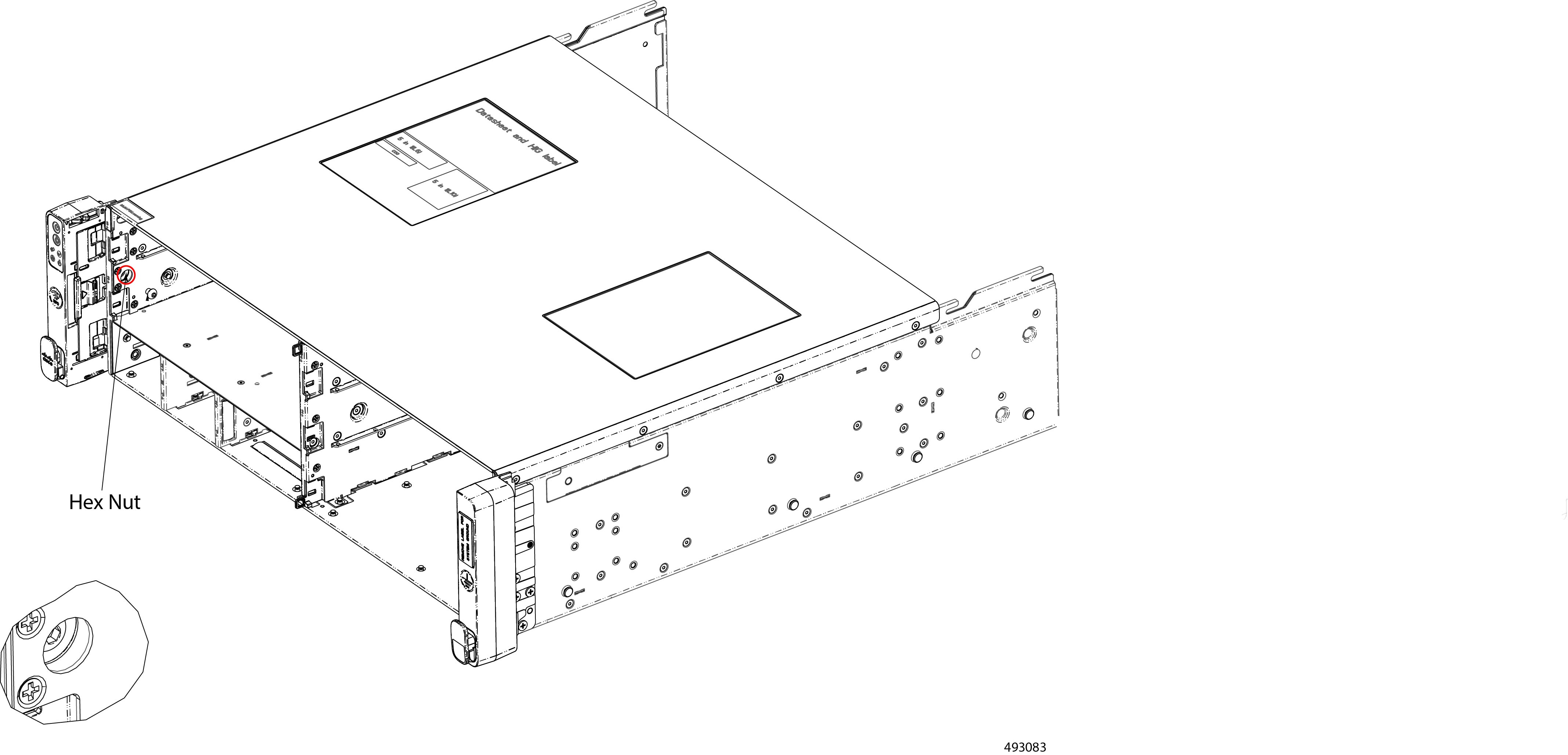
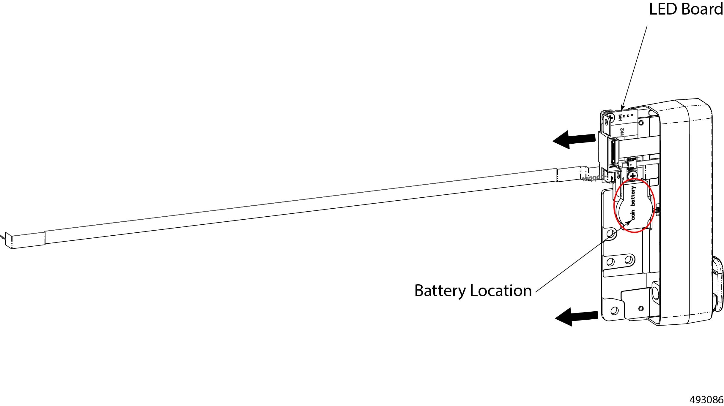
One battery is inside the left mounting bracket. This battery is called the chassis battery, and it is mounted on the LED board.
-
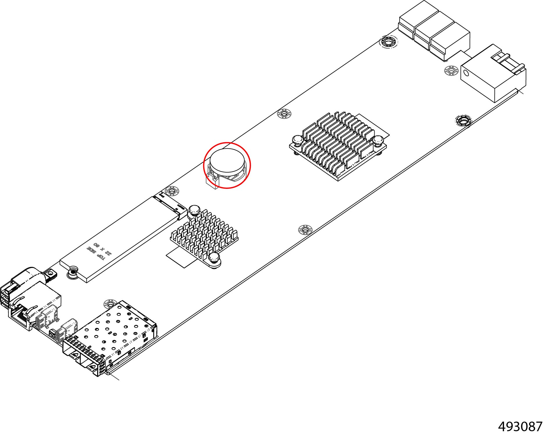
One battery is on the eCMC module. This battery is called the eCMC battery, and it is mounted directly on the module's motherboard.
Each battery sits in a clip that is accessible after removing some components. After components are removed, you can remove the battery with your fingers.
The battery is not a FRU, so remove it for recycling purposes only.
 Warning |
Recyclers: Do not shred the battery! Make sure you dispose of the battery according to appropriate regulations for your country or locale. |
Use the following tasks to recycle the batteries.
Recycling the Chassis Battery
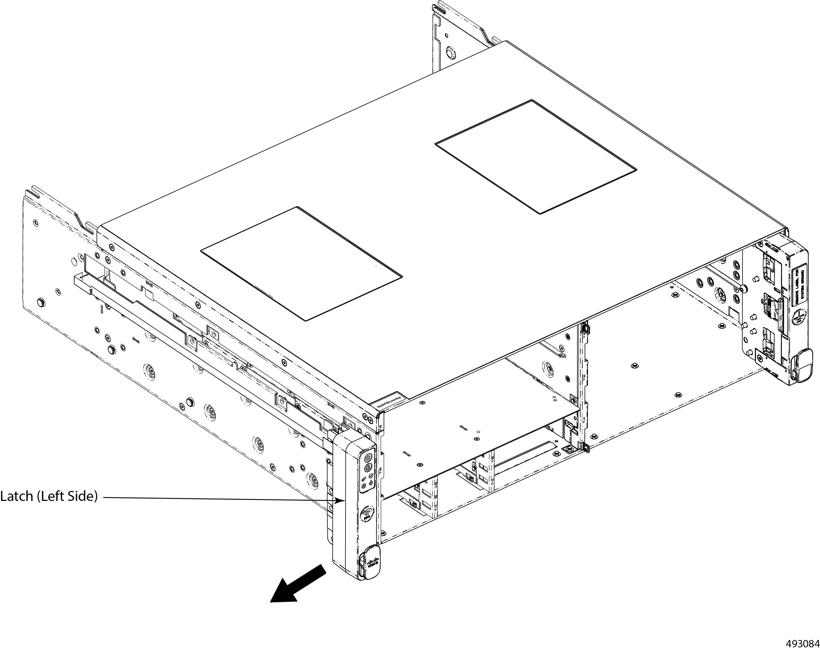
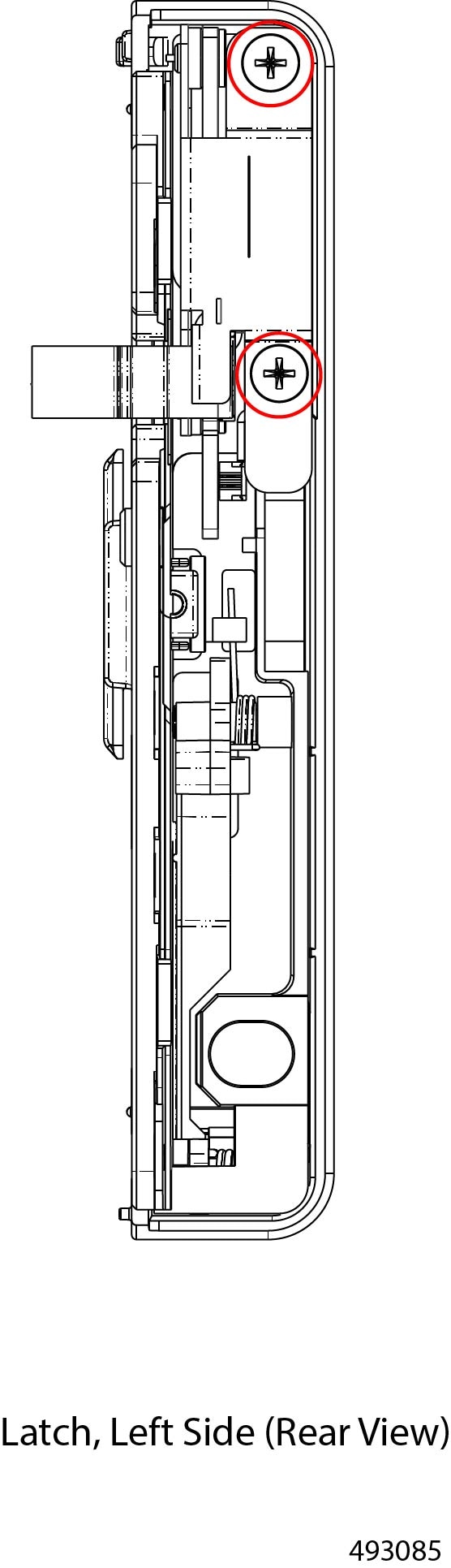
The Cisco UCS XE9305 modular system has a chassis battery built into the left mounting bracket. This component contains latch and LED board, and the chassis battery is located on the LED board.
 Caution |
The chassis battery is not a standard field-service procedure. This procedure is intended for recyclers only! |
To remove the chassis battery, you will need to disassemble different parts of the chassis to enable access to the battery.
Before you begin
If you have not already disconnected the chassis from facility power, do so now.
Gather the following tools:
-
One #2 Phillips screwdriver
-
One hexhead wrench or hex nut driver
Warning |
Recyclers: Do not shred the battery! Make sure you dispose of the battery according to appropriate regulations for your country or locale. |
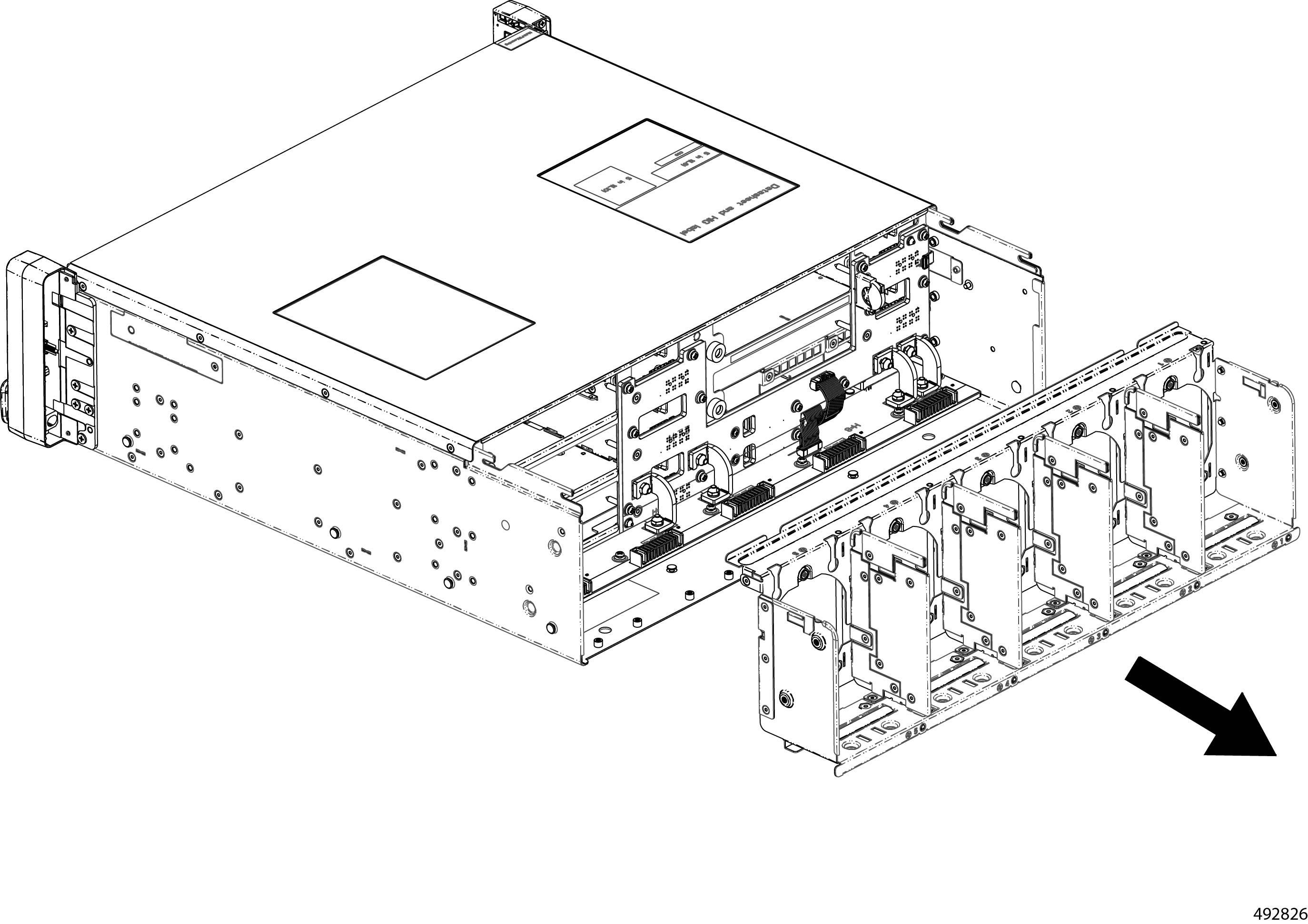
To complete this procedure, the fan module, fan tray, and the chassis backplane must already be removed to enable access the component that contains the chassis battery.
Procedure
|
Step 1 |
If you have not already removed the fan module, fan tray, and the chassis backplane, do so now. |
|
Step 2 |
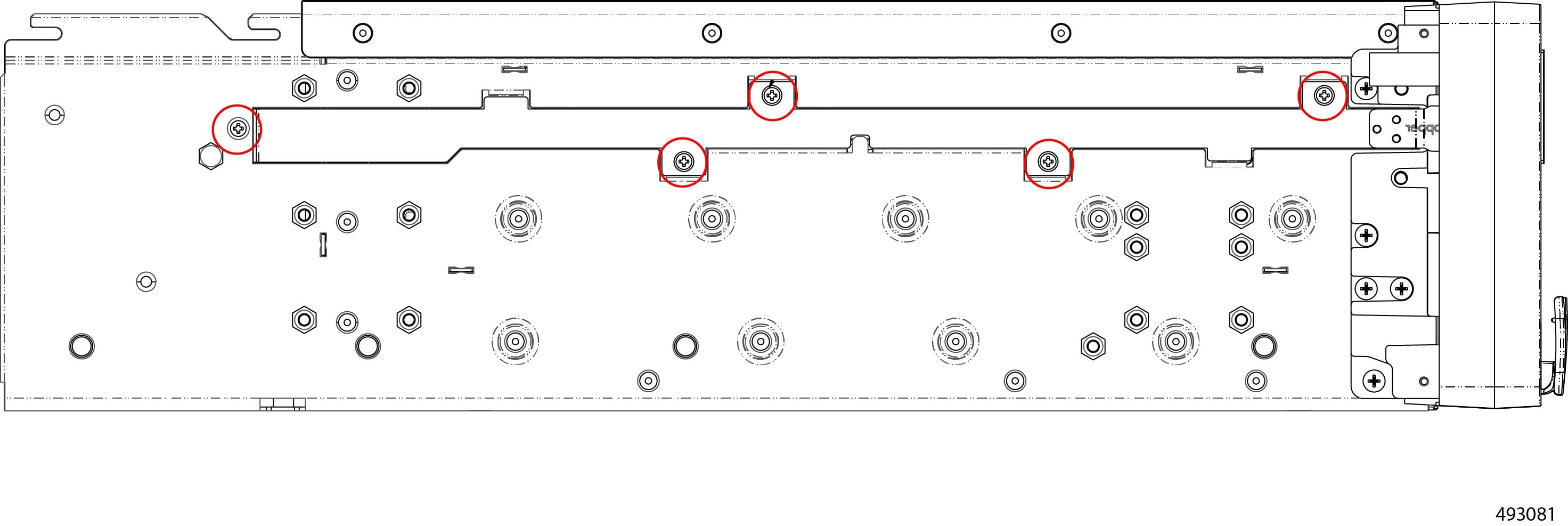
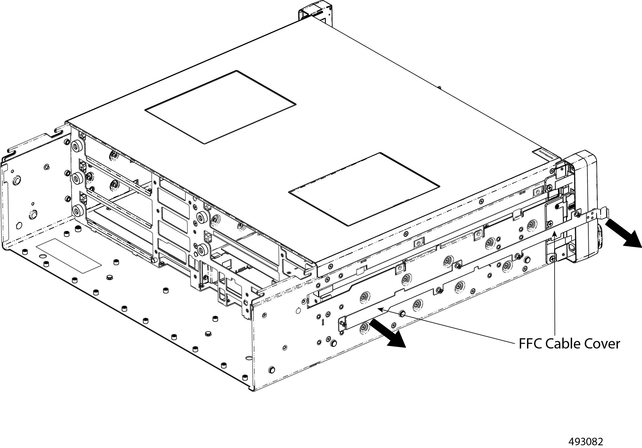
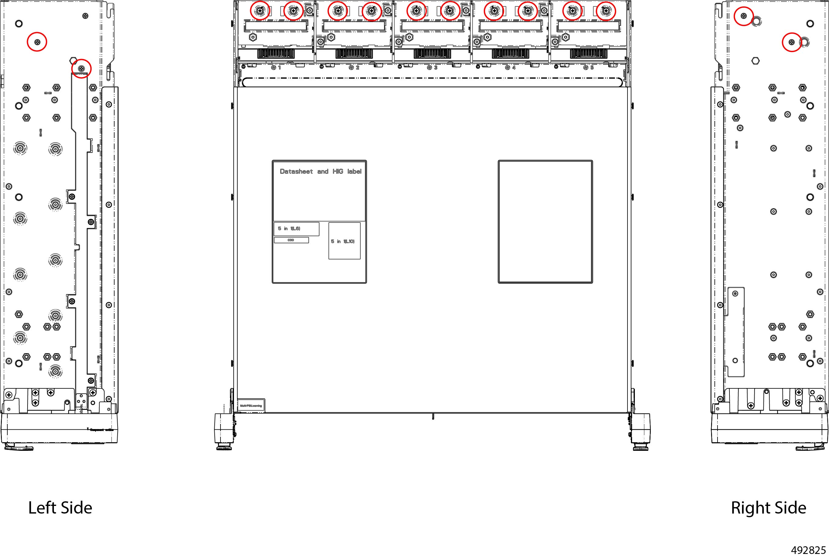
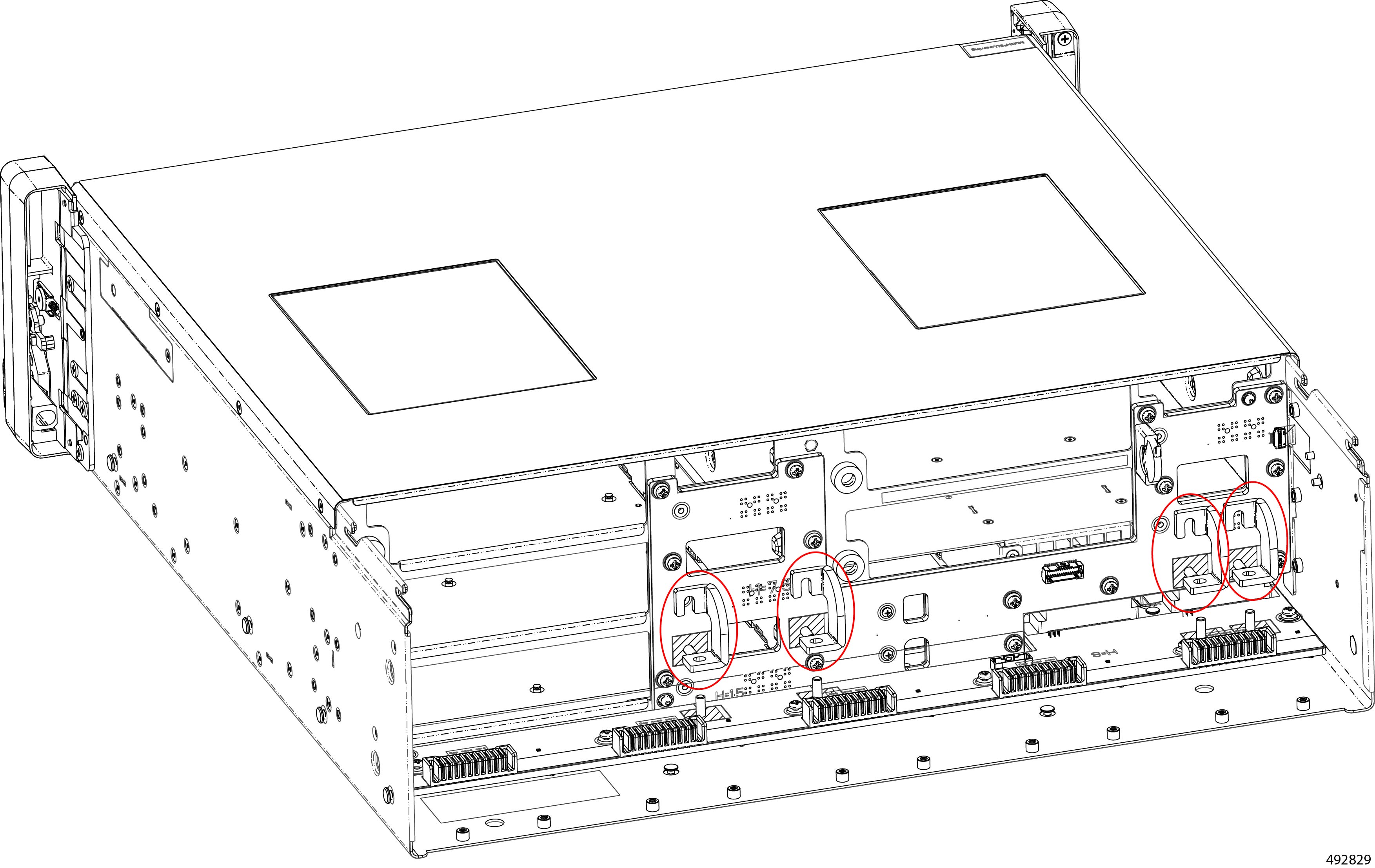
Remove the FFC cable cover from the left side of the chassis.
|
|
Step 3 |
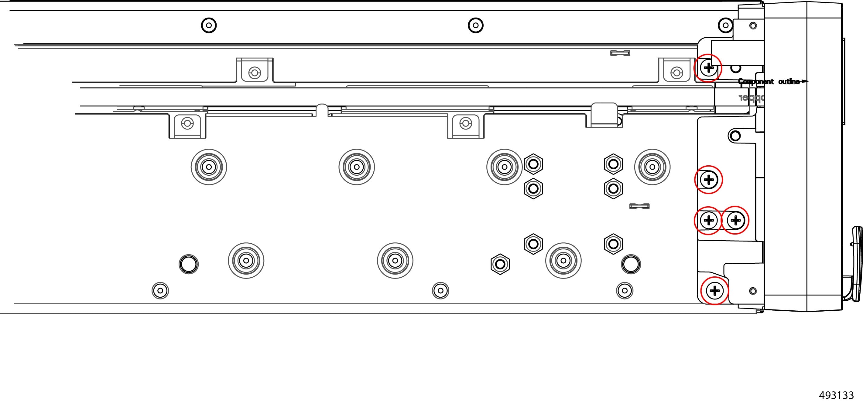
Remove the left side mounting bracket (latch).
|
|
Step 4 |
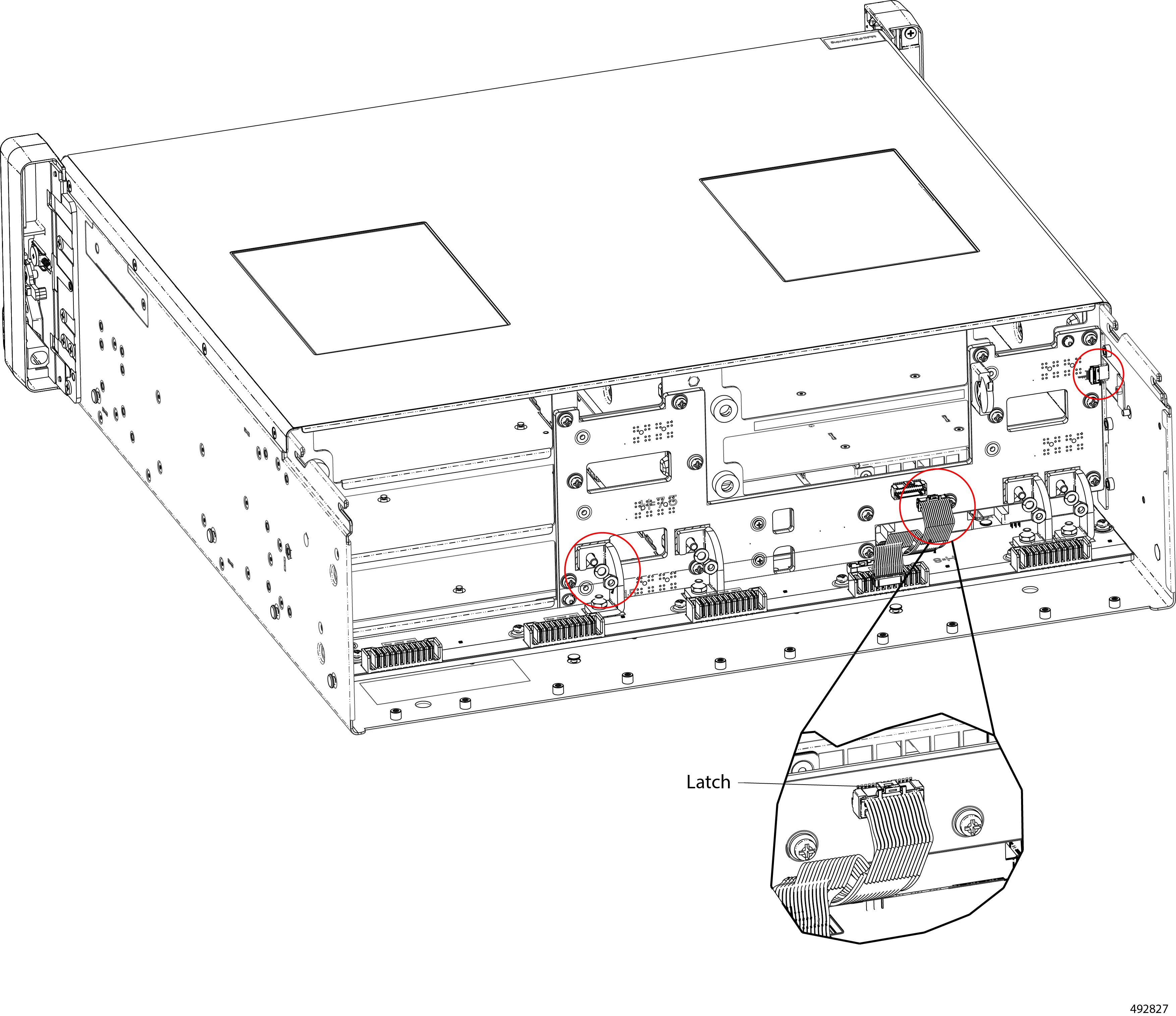
Remove the battery.
|
|
Step 5 |
Dispose of the chassis battery in compliance with your local ewaste and recycling regulations. |
Recycling the eCMC Battery
The eCMC module has a battery that sits horizontally on the module's PCB.
Caution |
Recycling the eCMC battery is not a standard field-service procedure. This procedure is intended for recyclers only! |
Use the following task to recycle the eCMC module's battery.
Before you begin
Warning |
Recyclers: Do not shred the battery! Make sure you dispose of the battery according to appropriate regulations for your country or locale. |
Procedure
|
Step 1 |
Remove the eCMC module. Go to Removing the eCMC Node. |
|
Step 2 |
Remove the module's top cover. |
|
Step 3 |
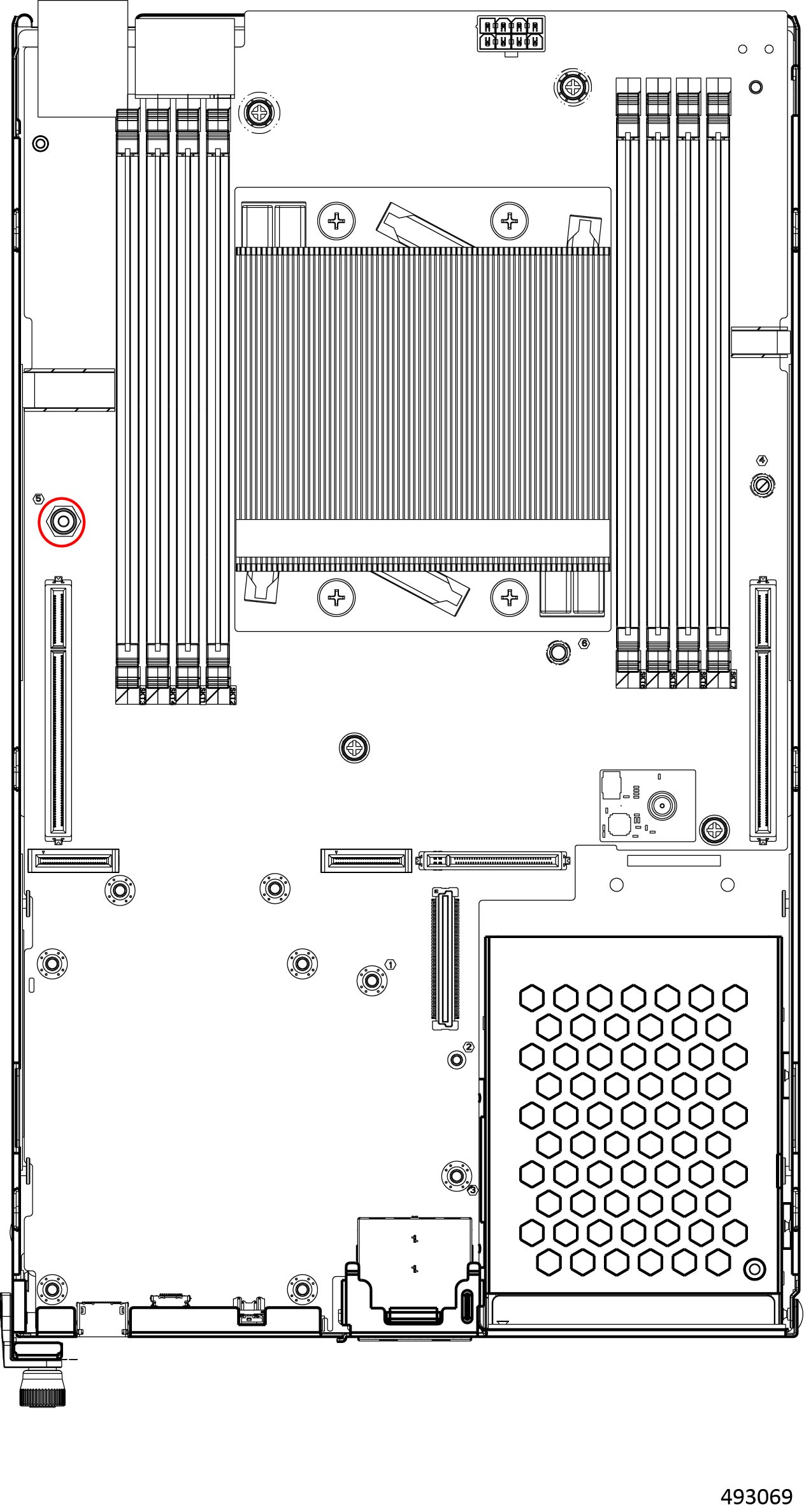
Locate the battery.
|
|
Step 4 |
Open the battery slot and remove the battery. |
|
Step 5 |
Dispose of the chassis battery in compliance with your local ewaste and recycling regulations. |
Recycling PCB Assemblies
The Cisco UCS XE9305 Chassis has multiple printed circuit board (PCB) assemblies that must be recycled in compliance with your local ewaste and recycling regulations.
Use the following tasks to recycle the chassis PCBAs (PCB assemblies):
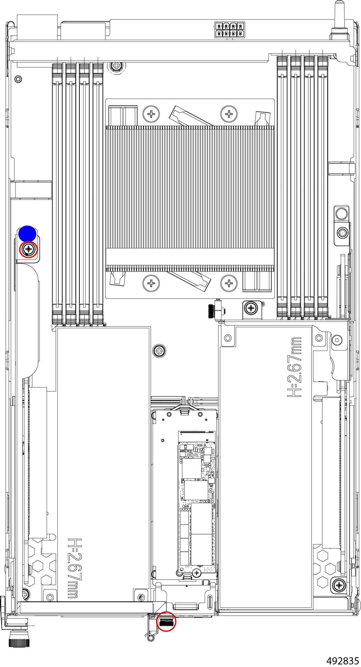
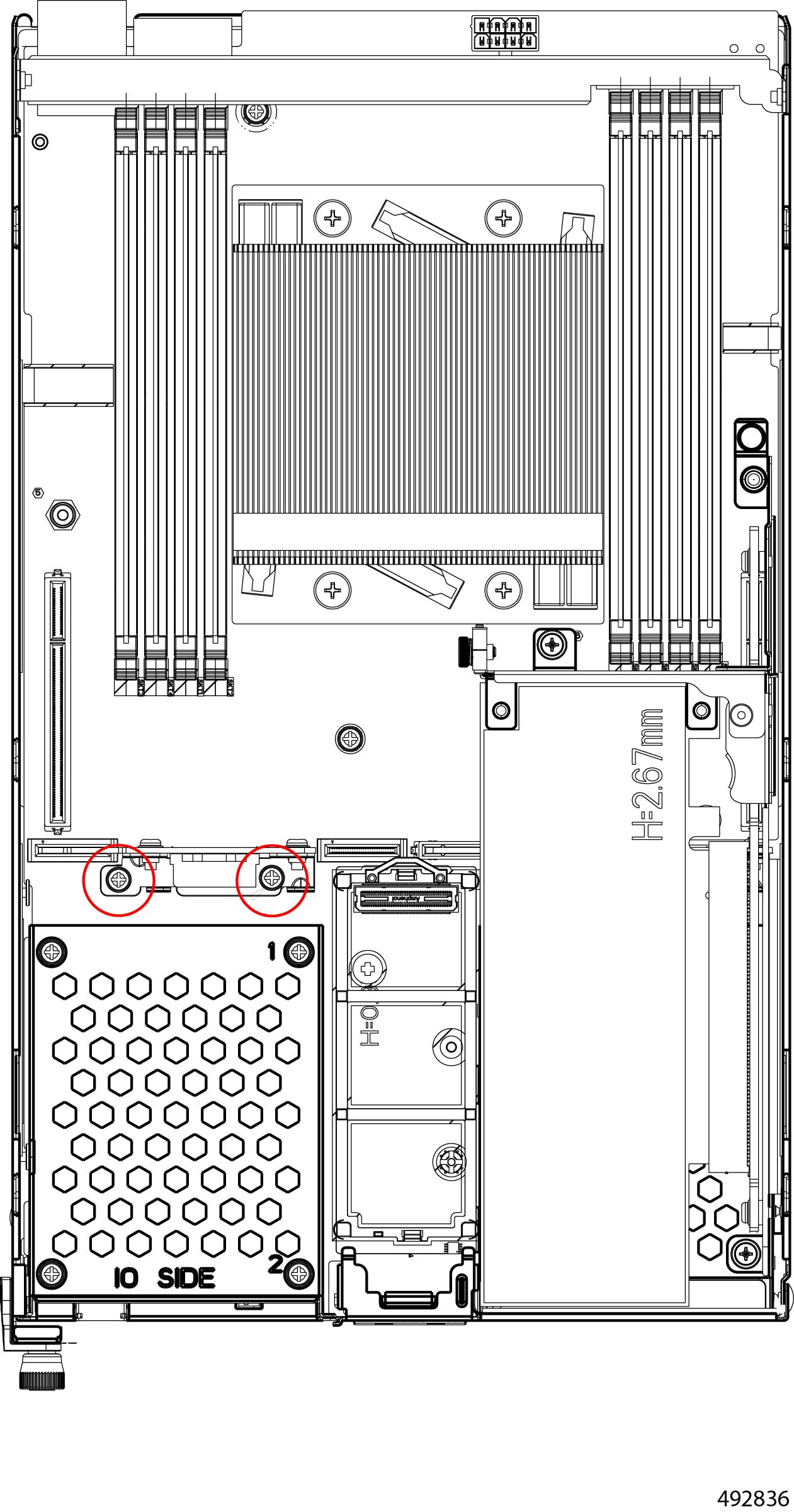
Recycling the Cisco UCS XE130c Compute Node PCB
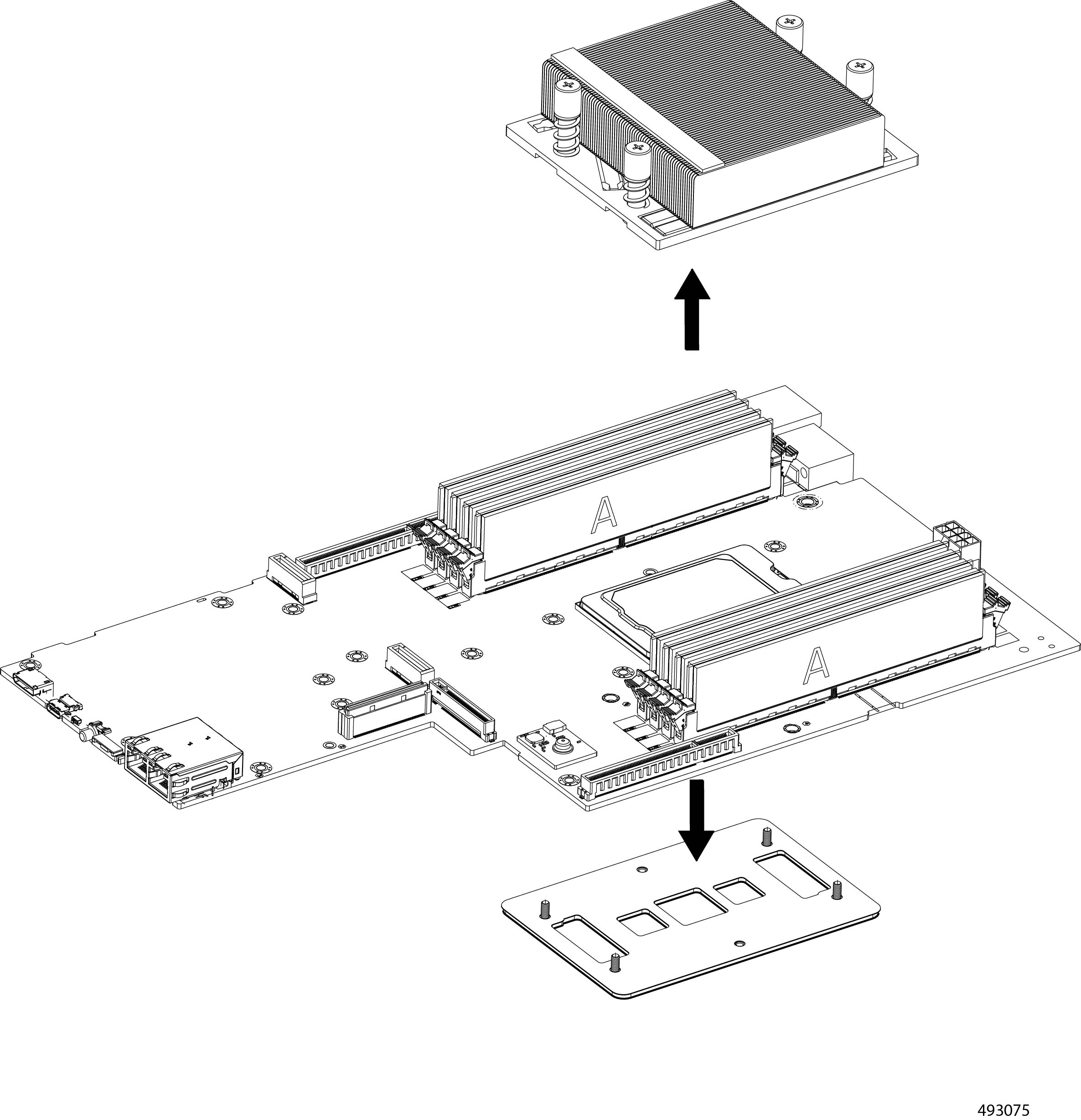
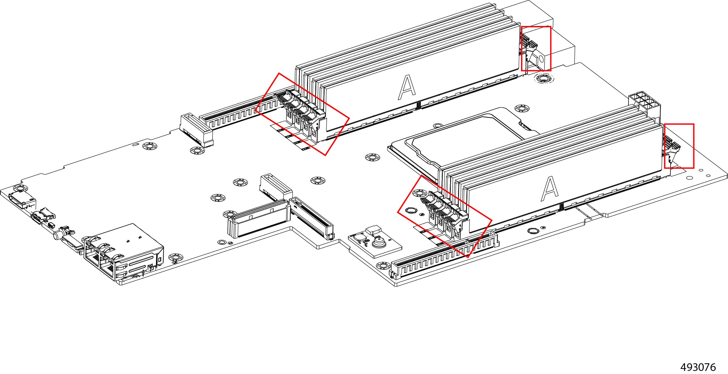
The Cisco UCS XE130c Compute Node contains a PCB. To remove the PCB for recycling, you must also remove additional components such as PCIe cards, DIMM modules, the CPU and heatsink.
Use this procedure to recycle the XE130c compute node's PCB.
Before you begin
Gather the following tools:
-
One #1 Phillips (cross-head) screwdriver
-
One #2 Philips (cross-head) screwdriver
-
One #8 hexhead wrench or hex nut driver
Some components on the XE130c compute node have designated touch points where you should grasp the component. Touch points are indicated in these illustrations as a solid blue circle. When indicated, use the touch point. Do not grasp the component at any other locations than the touch point when the touch point is shown.
Procedure
|
Step 1 |
Remove the node's top cover. Go to Removing a Node Top Cover. |
|
Step 2 |
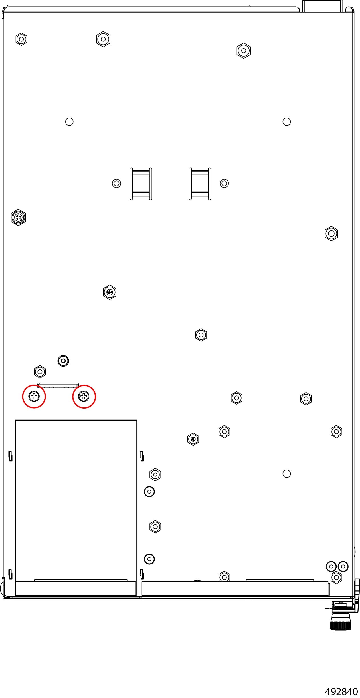
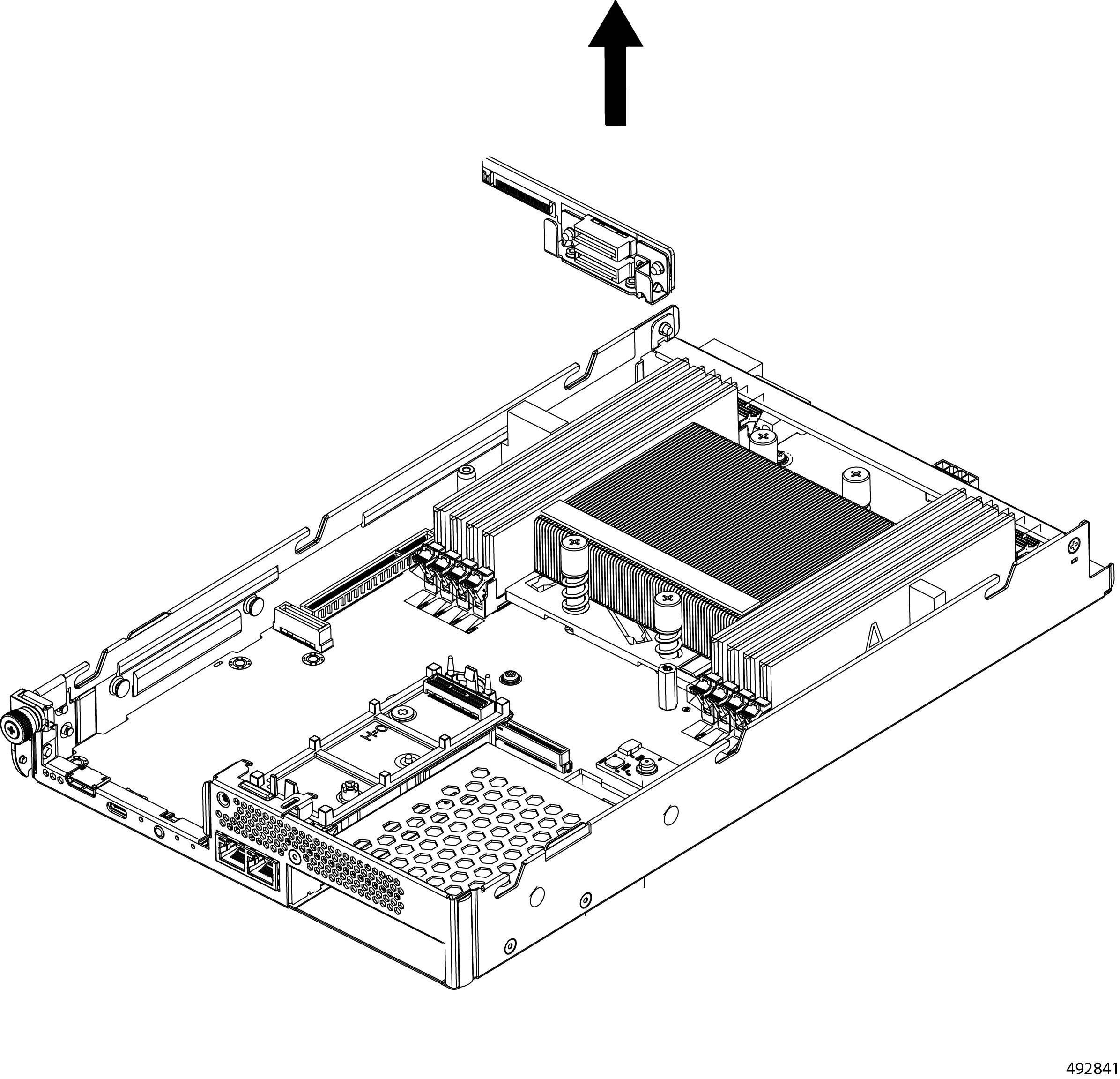
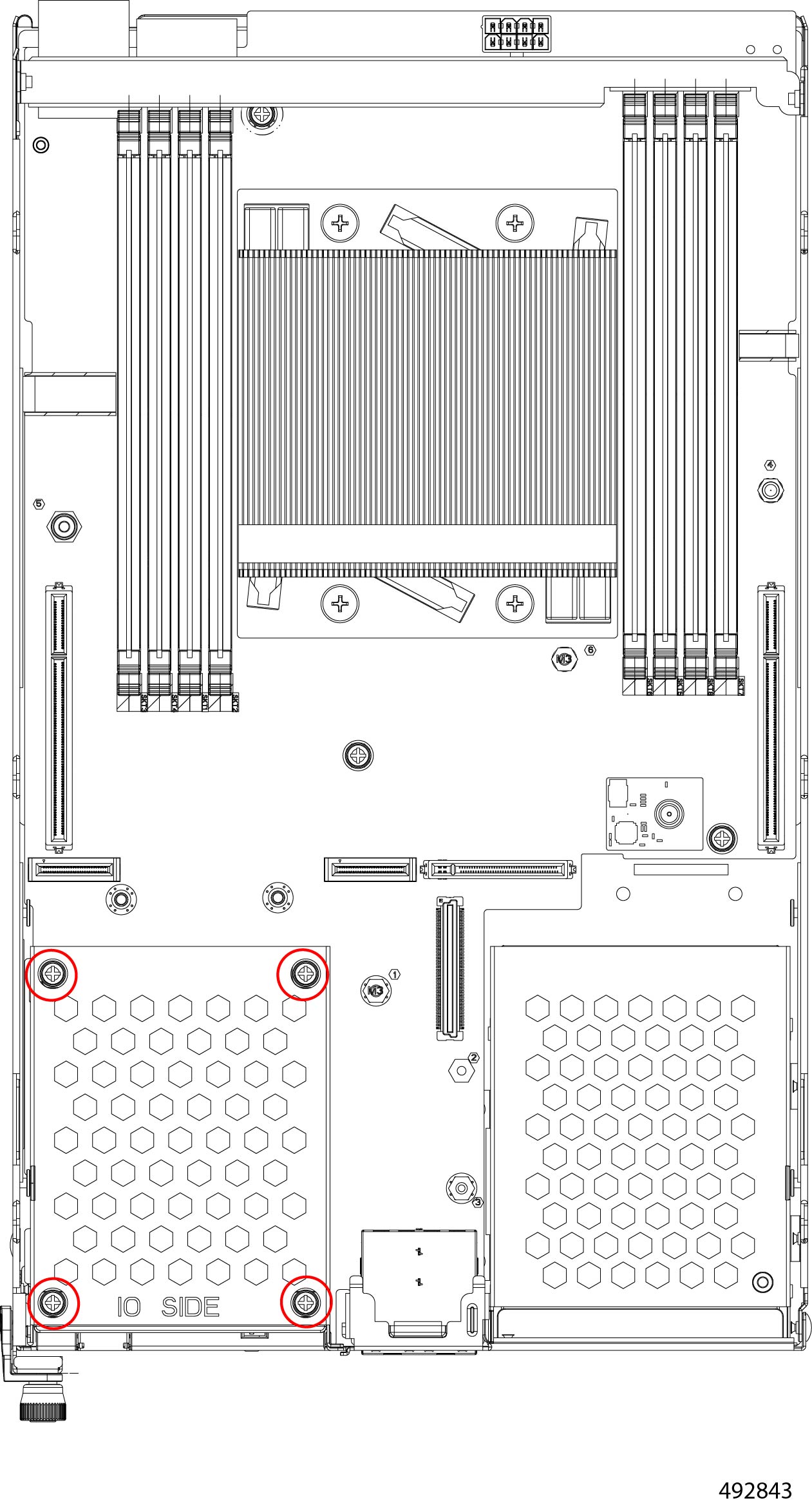
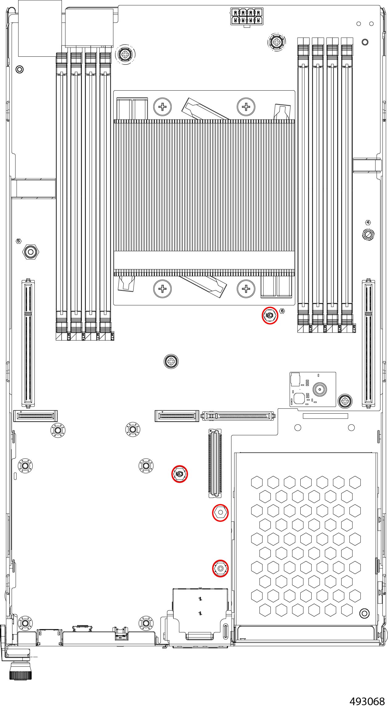
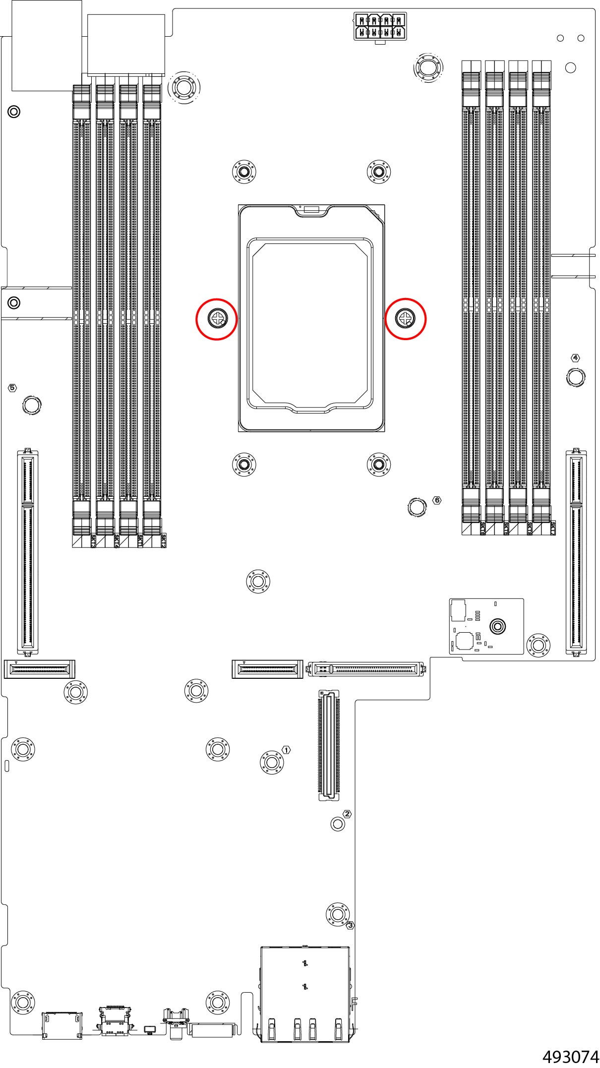
Remove the left PCIe module.
|
|
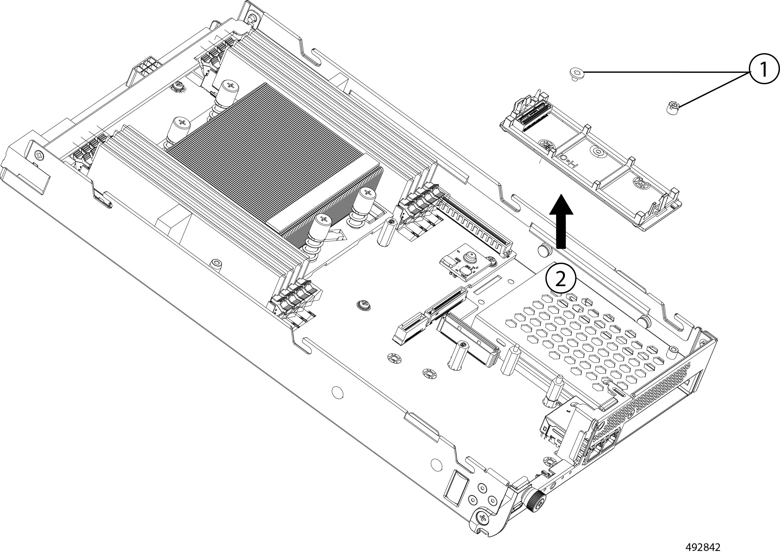
Step 3 |
If the compute node is configured for a PCIe card, remove the PCIe module from the left PCIe cage.
|
|
Step 4 |
Remove the left ES.3 backplane module.
|
|
Step 5 |
Remove the right PCIe module.
|
|
Step 6 |
Remove the right ES.3 backplane module.
|
|
Step 7 |
Remove the M.2 module.
|
|
Step 8 |
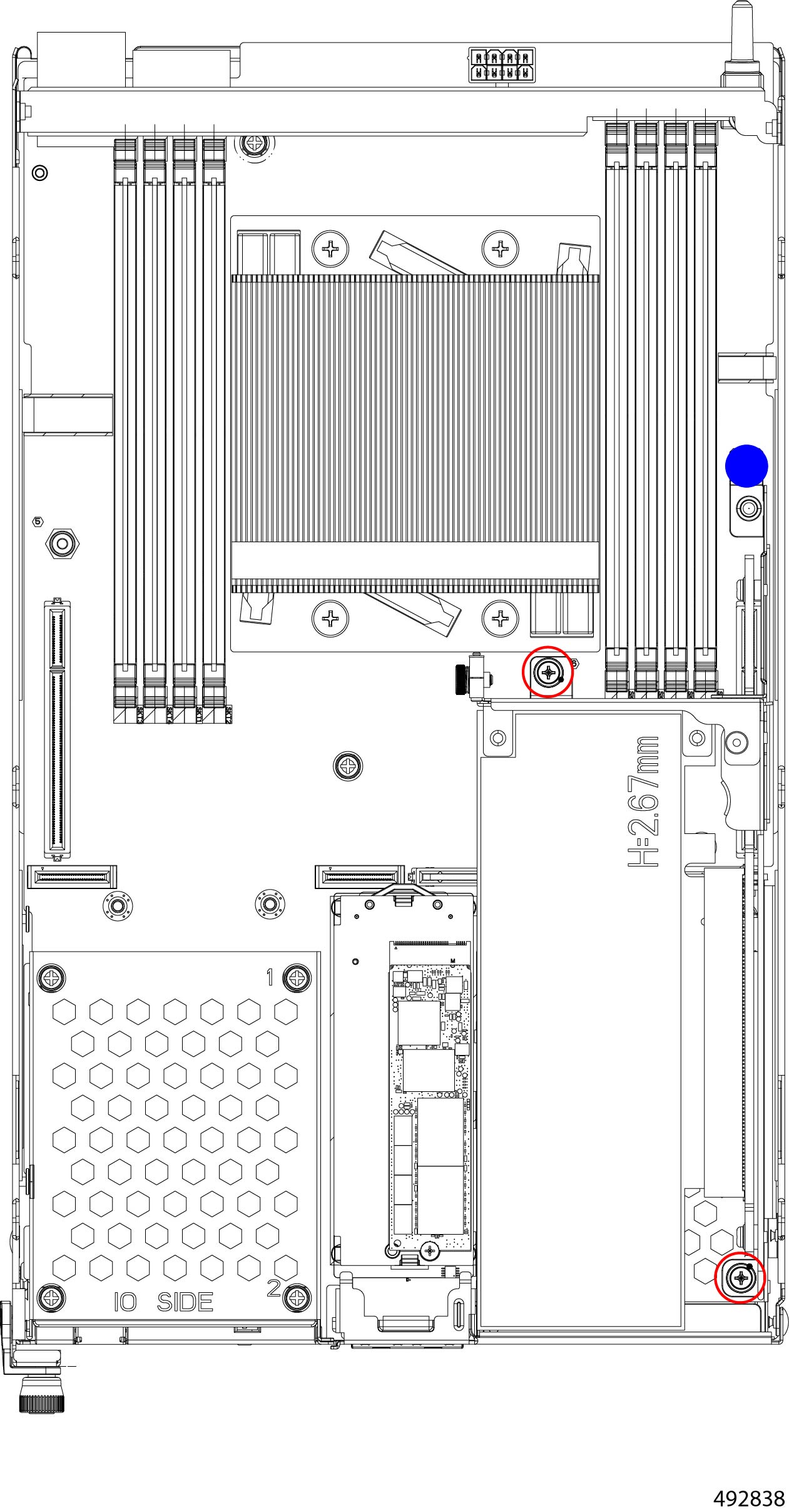
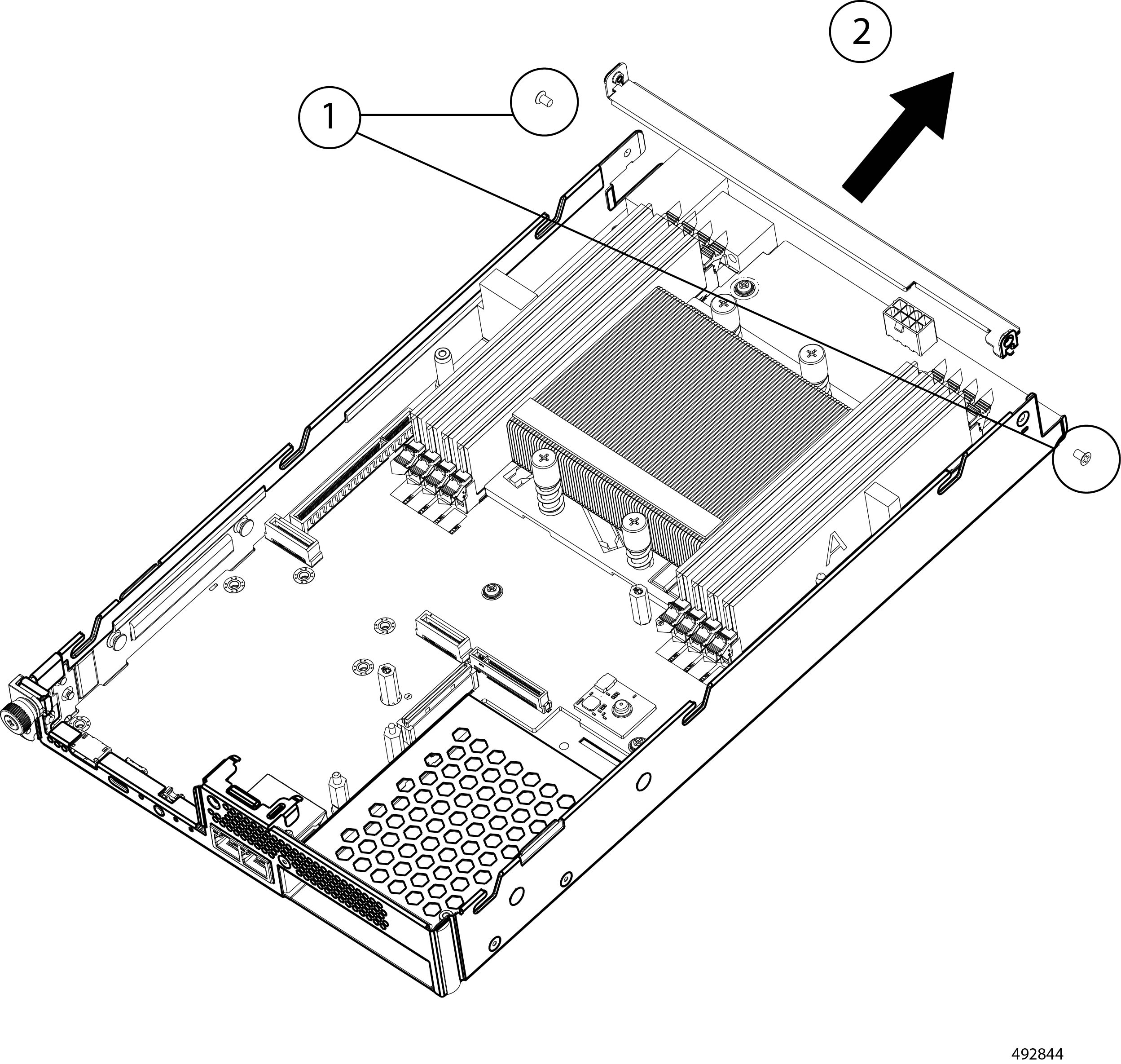
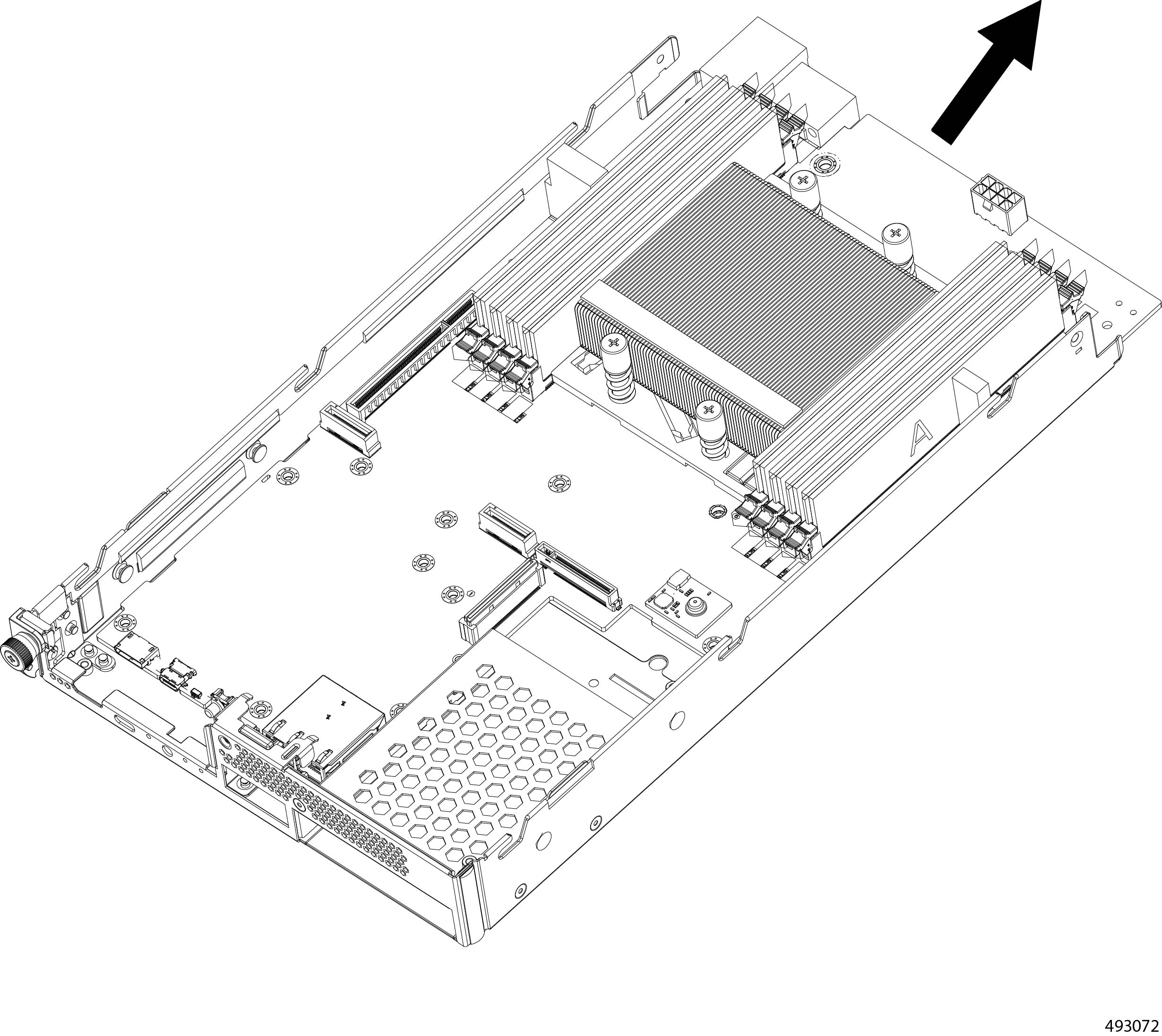
Remove the node PCB.
|
|
Step 9 |
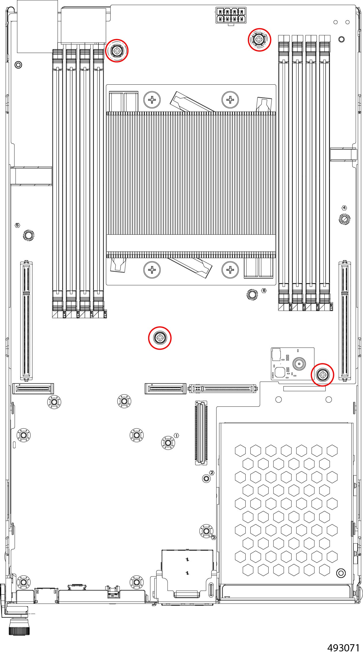
Remove the remaining components from the node's PCB.
|
|
Step 10 |
Recycle the DIMM modules. |
|
Step 11 |
Dispose of the compute node PCB and related components in compliance with your local ewaste and recycling regulations. |
Recycling the Cisco UCS eCMC Module PCB
The eCMC module contains a PCB. To remove the PCB for recycling, you must also remove additional components such as the M.2 Module and a battery.
Use this procedure to recycle the eCMC module's PCB.
Before you begin
Gather a #2 Philips (cross-head) screwdriver
Warning |
Recyclers: This module contains a CR2032 coin-style battery. Do not shred the battery! Make sure you dispose of the battery according to appropriate regulations for your country or locale. |
Procedure
|
Step 1 |
Remove the eCMC module from the chassis. Go to Removing the eCMC Node. |
|
Step 2 |
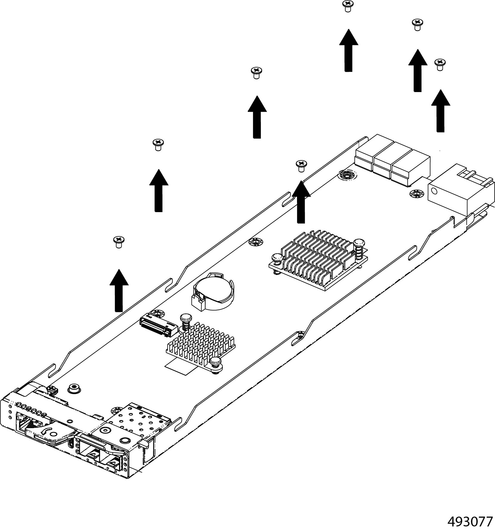
Remove the module's top cover. |
|
Step 3 |
If you have nor already removed the eCMC battery, do so now. Go to Recycling the eCMC Battery. |
|
Step 4 |
Remove the M.2 module. |
|
Step 5 |
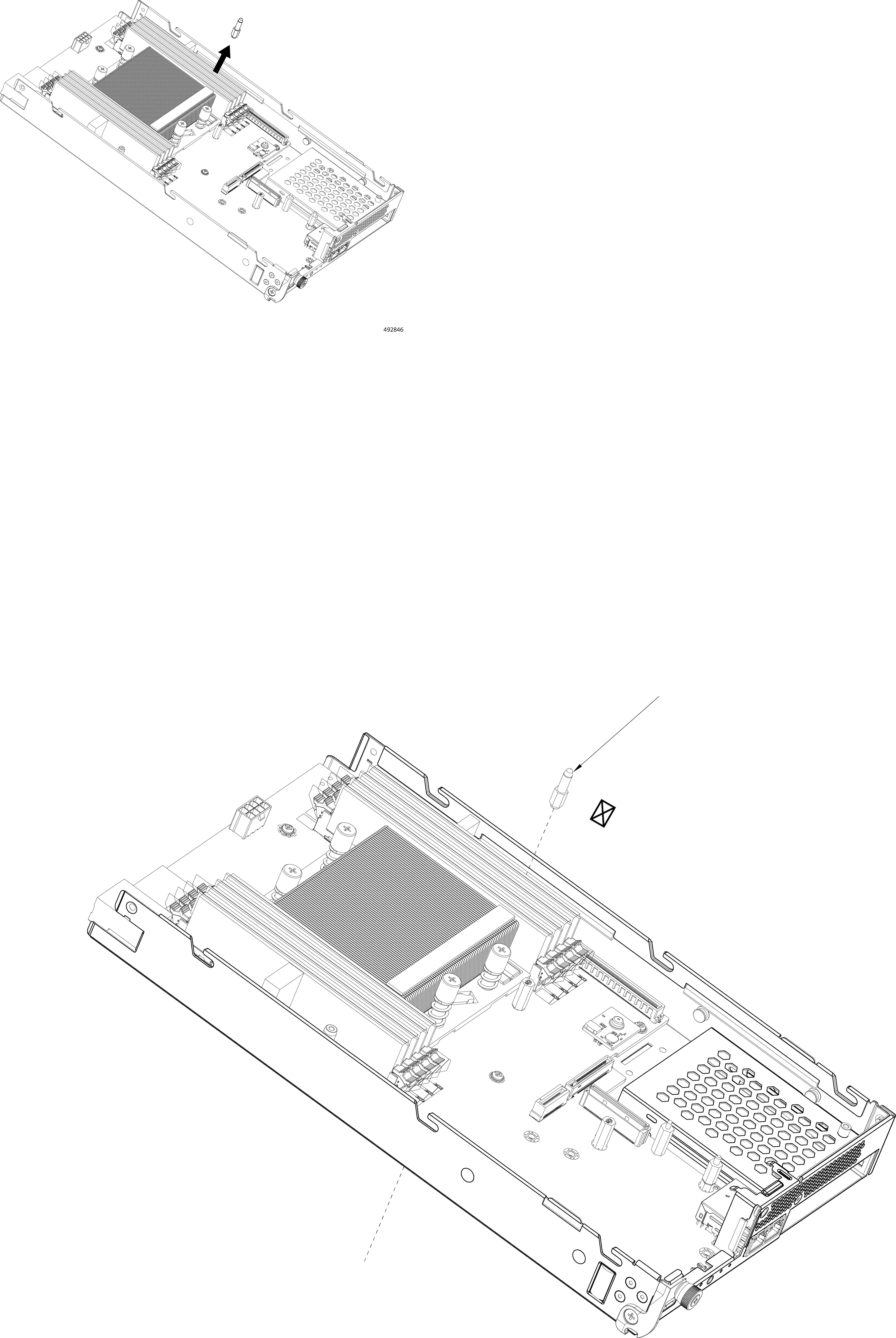
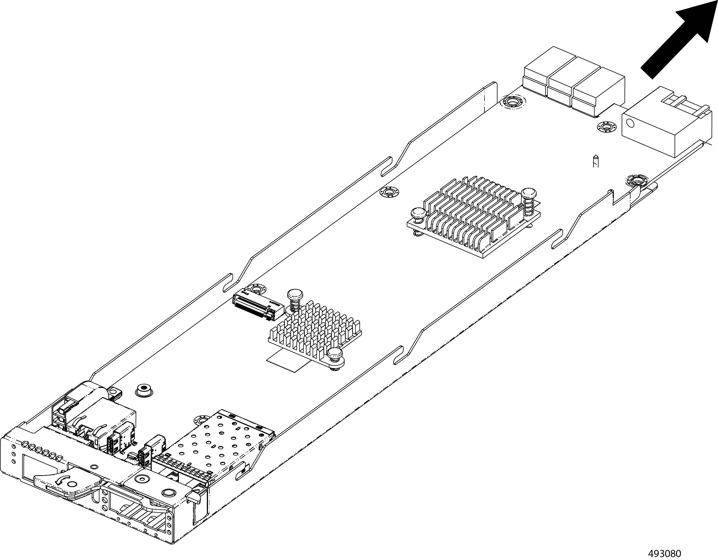
When the M.2 SSD is removed, detach the PCB from the sheetmetal tray.
|
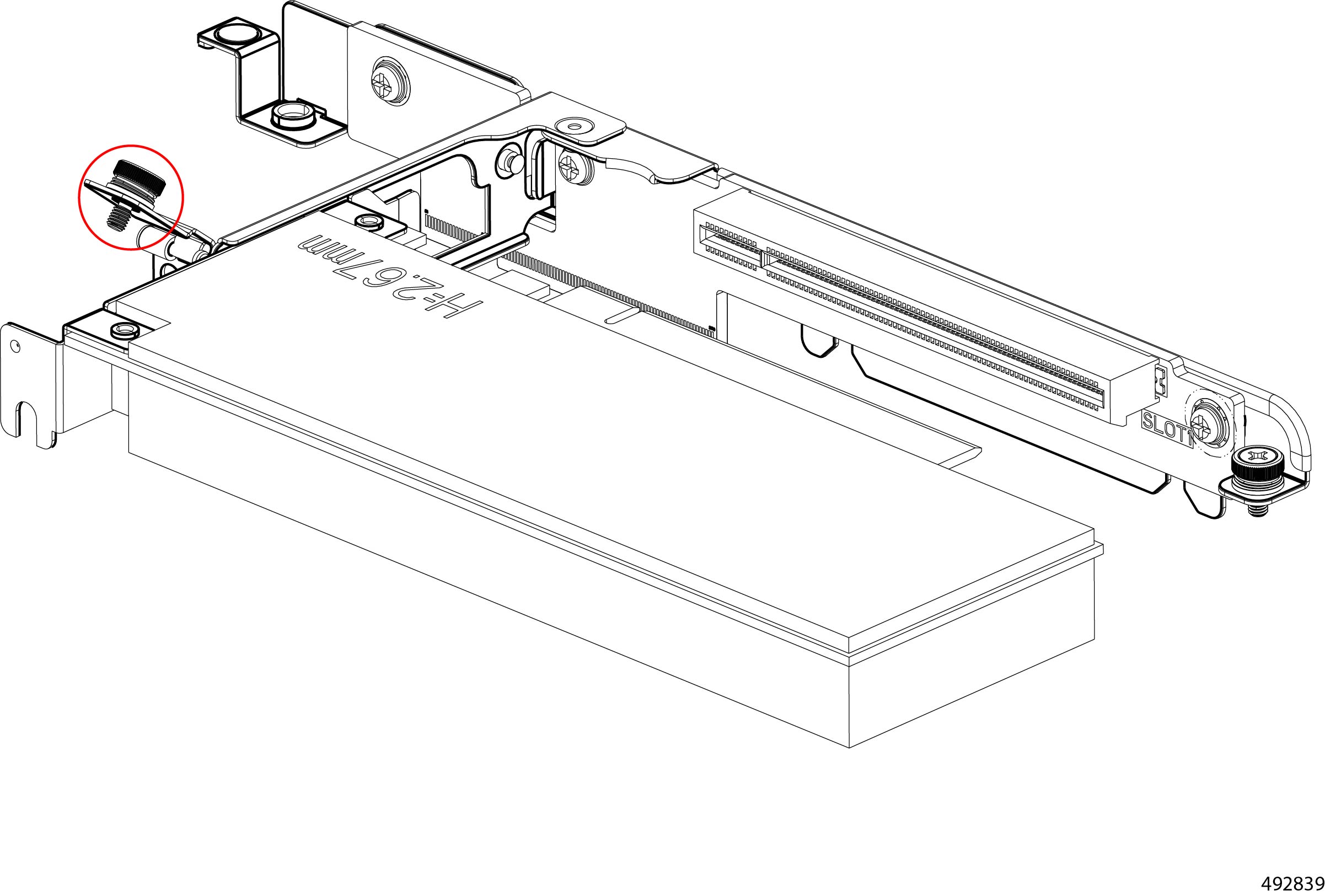
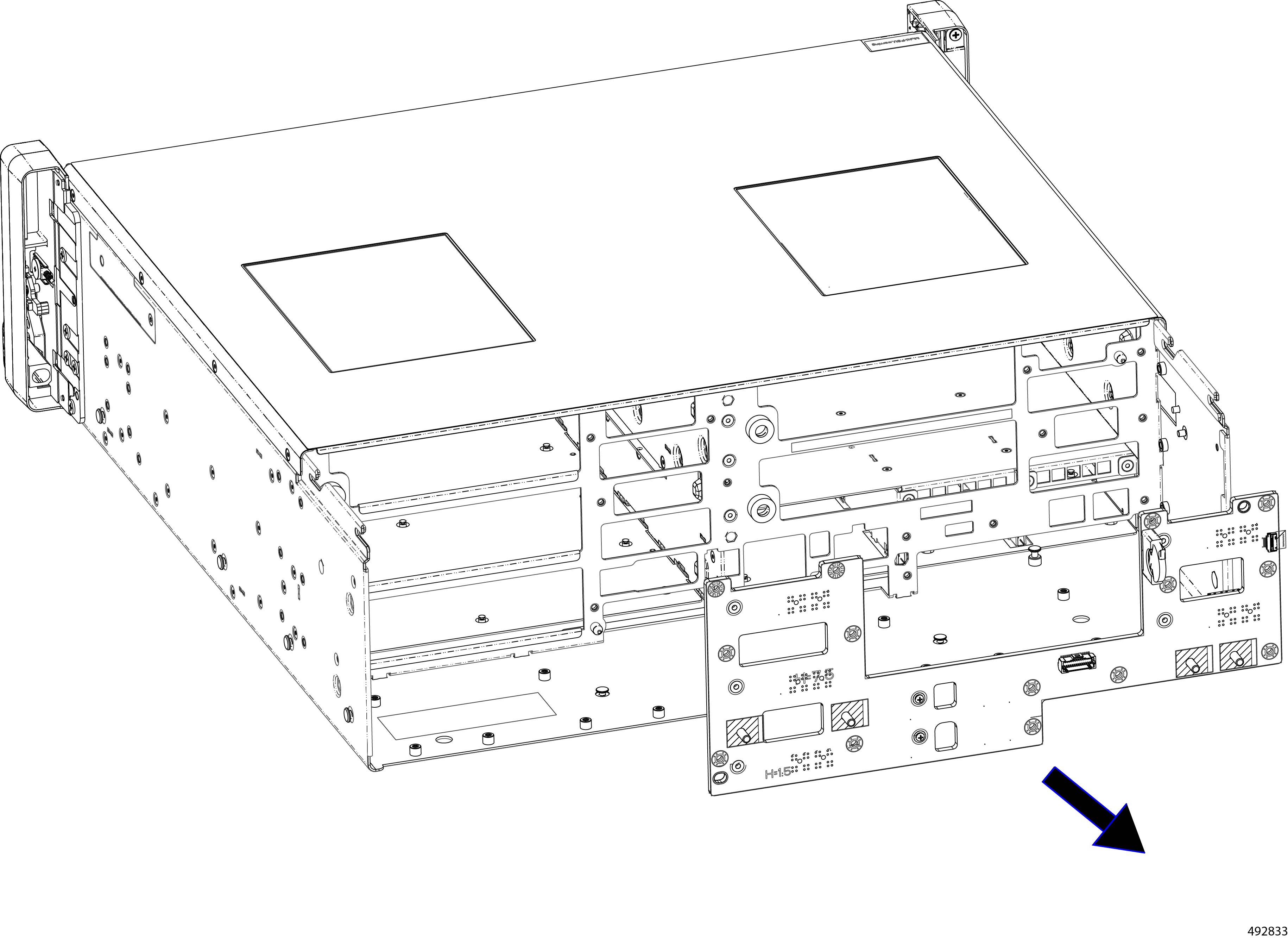
Recycling the Chassis Motherboard PCB
The chassis has a main PCB, the backplane PCB, that interconnects various subsystems. To remove the backplane PCB, you will need to disassemble different parts of the chassis to enable access to the PCB.
Before you begin
If you have not already disconnected the chassis from facility power, do so now.
Gather the following tools:
-
One #2 Phillips screwdriver
-
One 7mm socket wrench or nut driver
Procedure
|
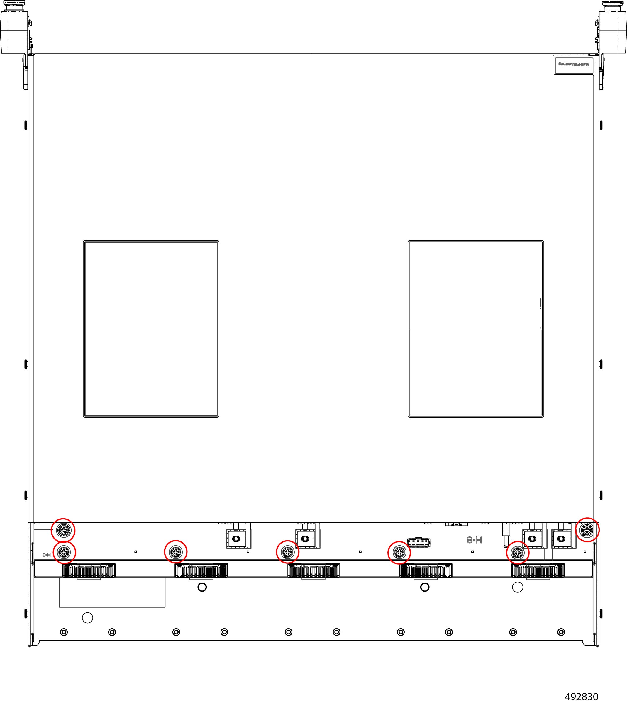
Step 1 |
Remove the top rear cover of the chassis.
|
|
Step 2 |
Remove the fan module. |
|
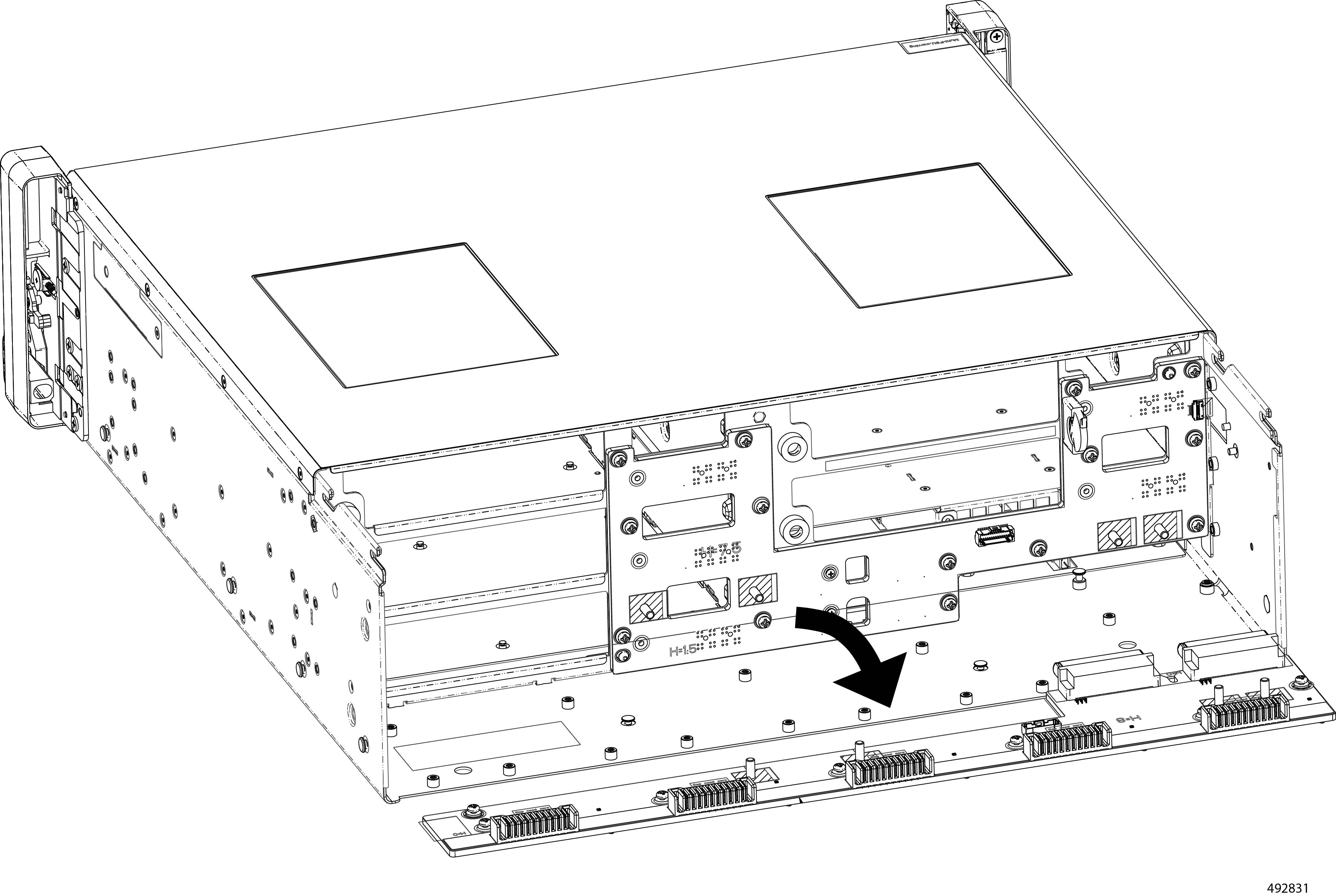
Step 3 |
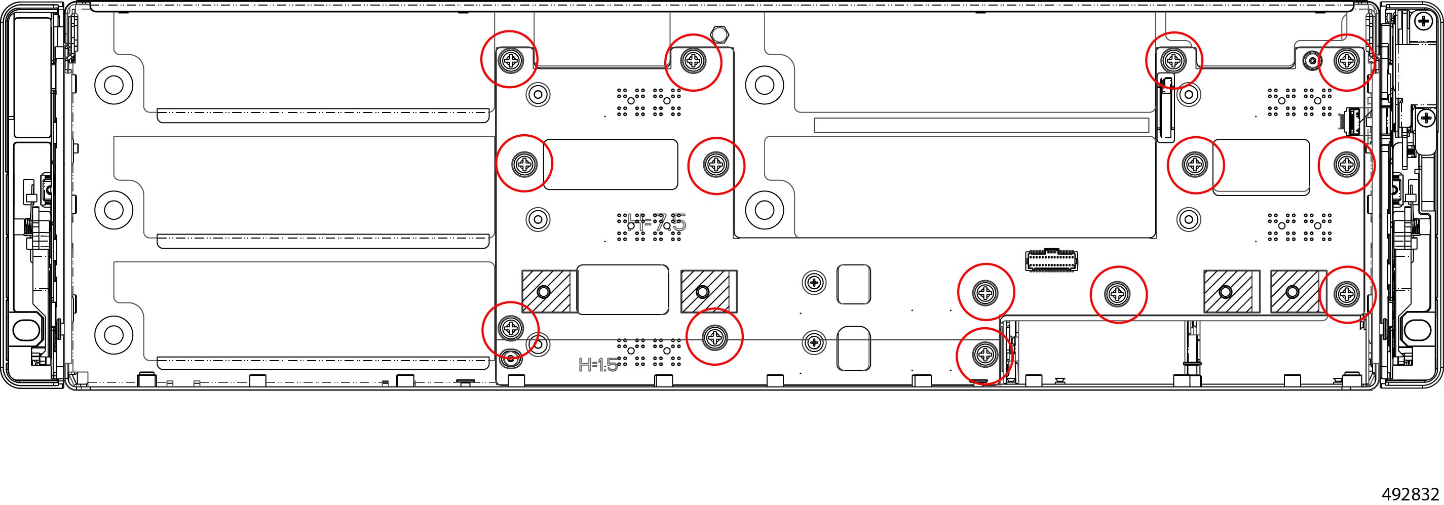
When the fan modules are removed, remove the fan tray.
The fan tray has a total of 14 screws, two per side and 10 on the fan tray.
|
|
Step 4 |
Grasp the fan tray, and detach it from the chassis.
|
|
Step 5 |
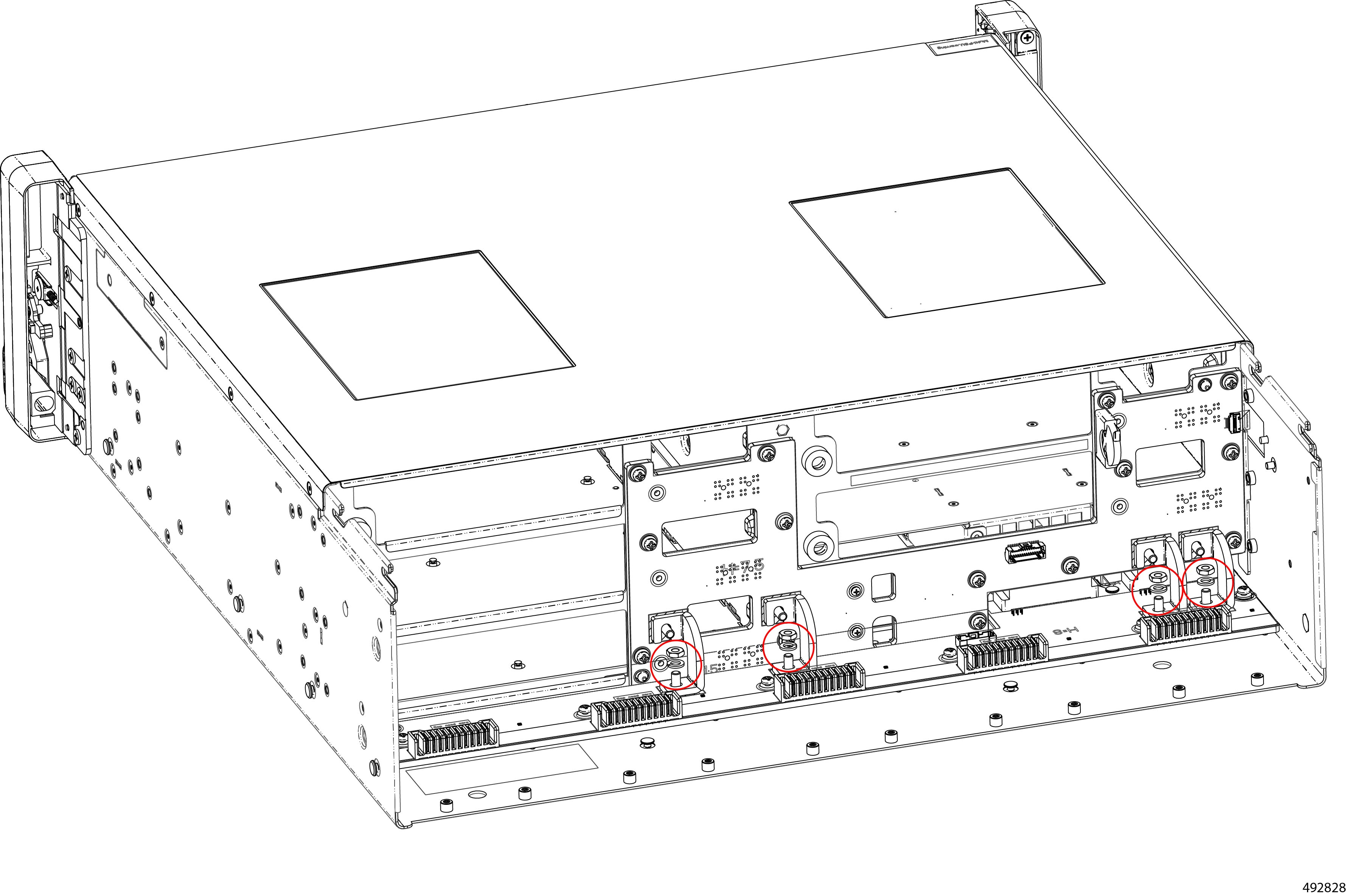
Remove the bus bar nuts and FFC Cable.
|
|
Step 6 |
Grasp and remove the bus bar.
|
|
Step 7 |
Remove the power bar.
|
|
Step 8 |
Remove the PCB.
|
|
Step 9 |
Dispose of the backplane PCB in compliance with your local ewaste and recycling regulations. |

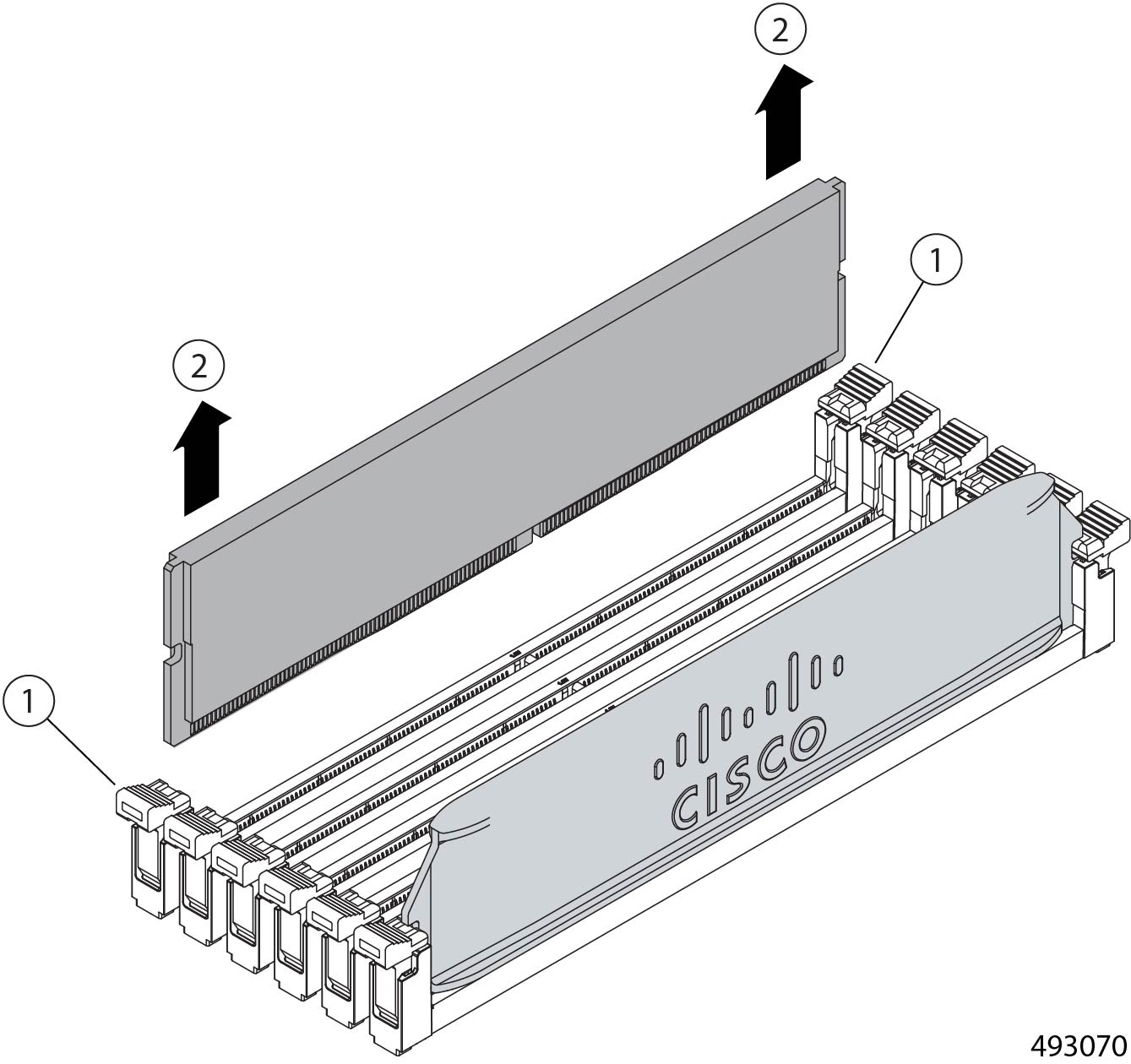
Recycling DIMMs
The Cisco UCS XE130c Compute Node contains DIMM memory modules that must be recycled in compliance with your local ewaste and recycling regulations.
DIMMs are arranged in banks connected to the node's CPU. Each DIMM module occupies one slot in the DIMM bank, and the DIMM module is held in place by connector latches.
Use the following tasks to recycle the DIMM modules.
Recycling the Compute Node DIMM Modules
DIMM modules must be recycled in compliance with your local ewaste and recycling laws. DIMMs are installed in slots on the compute node and held in place by connector latches.
Use this procedure to recycle DIMM memory modules.
Before you begin
Gather a #2 Phillips screwdriver.
Procedure
|
Step 1 |
Remove the compute node. Go to Removing a Compute Node. |
|
Step 2 |
Remove the node's top cover. |
|
Step 3 |
Remove the DIMM modules from the node.
|
|
Step 4 |
Dispose of the DIMMs in compliance with your local regulations for recycling and ewaste. |
Recycling Power Supplies
The Cisco UCS XE9305 Chassis features two hot-swappable 2400 W Titanium AC power supply units (PSUs) providing N+N redundancy. The PSUs are accessible from the front of the chassis.
PSUs must be recycled in compliance with your local ewaste and recycling regulations.
Recycling PSUs is a tool less process. You do not need to power down the chassis to recycle the PSUs, because when you remove enough PSUs, the chassis power management features will begin gracefully powering down the Cisco UCS XE9305 Modular System. However, it is a best practice to power down the chassis before recycling power supplies.
Recycling Power Supplies
The chassis has two PSUs that are accessible from the front of the chassis. You do not need any tools to recycle the power supplies.
Procedure
|
Step 1 |
Remove the PSUs Go to Removing Power Supply Units. |
|
Step 2 |
Recycle the PSUs in compliance with your local ewaste and recycling regulations. |
Recycling CPUs
Each Cisco UCS XE130c Compute Node contains a CPU that is connected to, and sits between, DIMM memory banks. The CPU is accessible by removing each compute node.
To recycle the CPU, you will need to remove the CPU's heatsink and disconnect the CPU from the socket. The CPU is not field-serviceable or easliy replaceable, so recycling it is a destructive process.
Recycling the XE130c Compute Node CPU
Each XE130c Compute Node has a CPU that must be recycled in compliance with your local ewaste and recycling regulations.
To recycle the CPU, you will need to remove the CPU's heatsink and disconnect the CPU from the socket. Each compute node features a BGA (Ball Grid Array) type CPU, which requires a hot air gun, soldering gun, or other equipment to heat the CPU and desolder it from the motherboard.
Before you begin
Gather a #2 Phillips (cross head) screwdriver.
A soldering gun, hot air gun, or similar tool to heat the connections between the CPU and the motherboard.
Procedure
|
Step 1 |
Remove the compute node. Go to Removing a Compute Node. |
|
Step 2 |
Using a #2 Phillips screwdriver, remove the heatsink from the node. 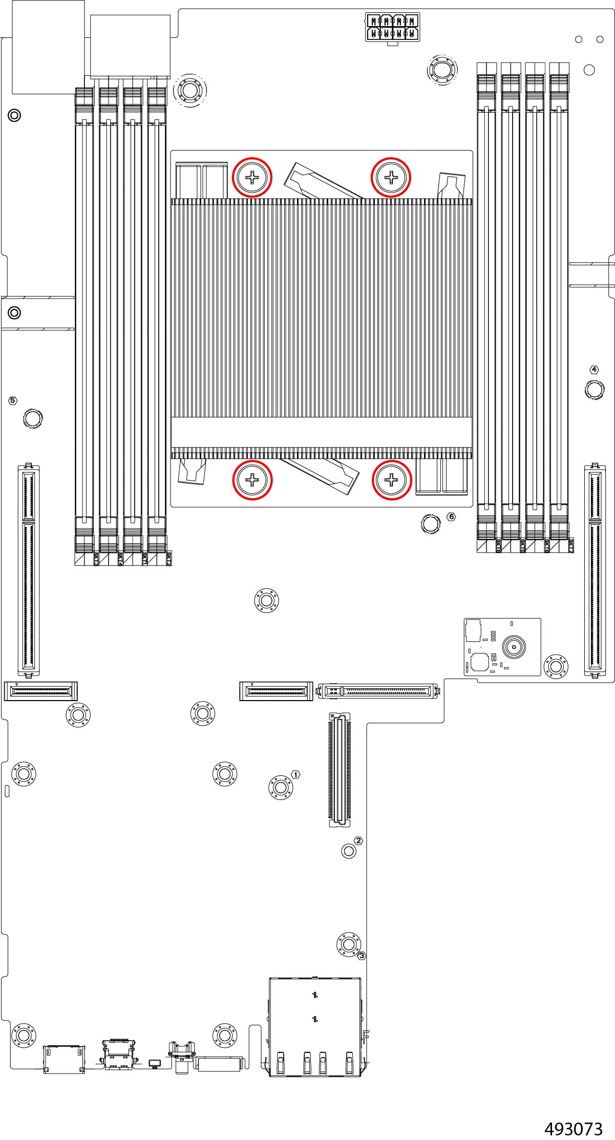 |
|
Step 3 |
Using a soldering gun, or other heating tool, desolder the CPU from the socket. |
|
Step 4 |
Dispose of the heatsink and CPU in compliance with your local ewaste and recycling regulations. |
 Feedback