Overview
Cisco Unified Edge Overview
Cisco Unified Edge brings together compute, storage, routing, switching, and security into a single configurable solution to help IT organizations simplify the deployment, operations, and lifecycle management of edge infrastructure at global scale.
Cisco Unified Edge is a fully integrated, edge-optimized, AI-ready, and SaaS managed platform, engineered to deliver a superior user experience with unprecedented visibility, consistency, and control for a host of edge use cases.
Cisco Unified Edge XE9305 Chassis Overview
At the heart of the Cisco Unified Edge solution is the Cisco UCS XE9305 modular system. A 3RU, short-depth, multi-mountable chassis, the Cisco UCS XE9305 provides five front-facing slots that can accommodate compute nodes that are easy to service and adaptable to deliver a range of capabilities, from computing to storage and networking to security.

Designed and built for edge locations and distributed computing environments running virtualized, containerized, or AI workloads, the Cisco UCS XE9305 modular system provides the following benefits:
-
Simplification of edge infrastructure and operations
-
Unification of typically disparate edge systems
-
Redefinition of edge solutions
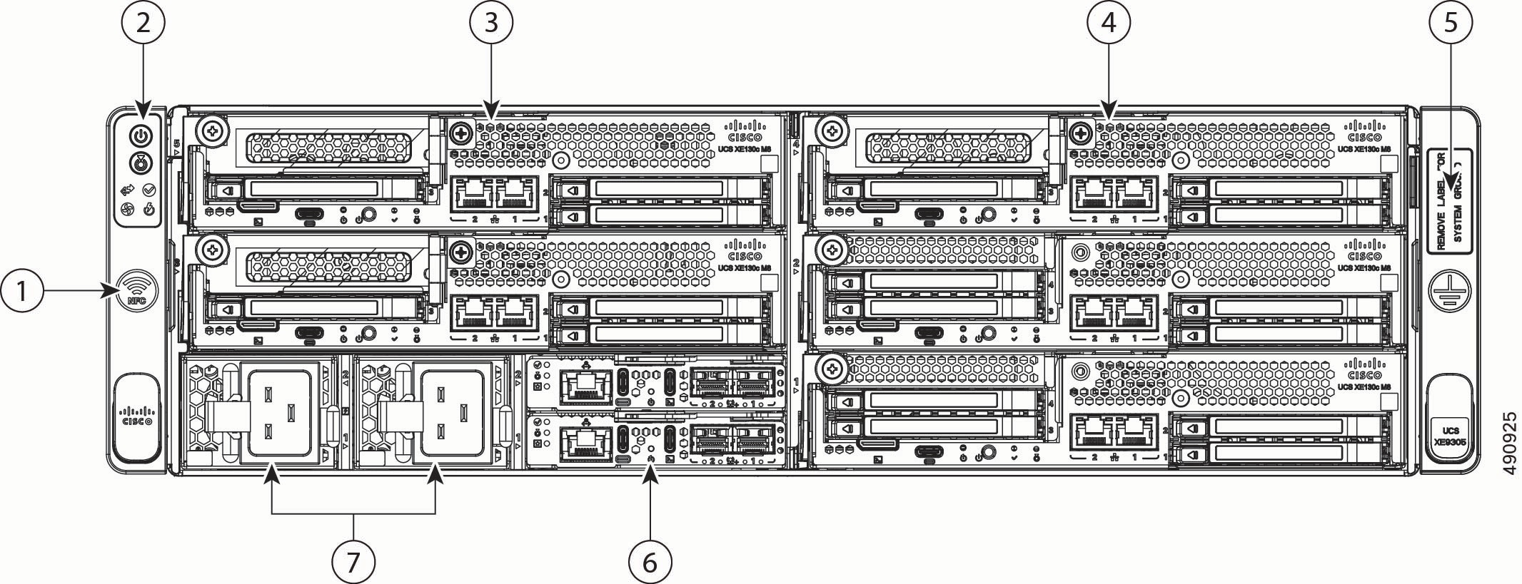
Front Panel
The front panel of the Cisco UCS XE9305 modular system contains the following hardware features.
|
1 |
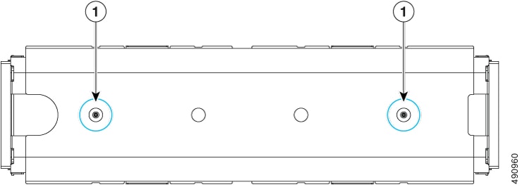
Icon indicating Near-field Communication (NFC) antenna location. Indicates the location to connect NFC devices. |
2 |
Chassis Health and Status LEDs. For more information, see Chassis Health LEDs. |
|
3 |
Slots for compute nodes and other modules. These slots are numbered 1 through 5, bottom up and right to left. So, slot 1 is at the bottom right slot, and slot 5 is at the top left. Slot numbers are labeled on the front panel for easy identification. |
4 |
Slots for compute nodes that support either network or storage. |
|
5 |
Electrical earth ground pad. |
6 |
Edge Chassis Management Controller (eCMC) modules, two installed for redundancy. Slots are numbered from bottom to top, so slot 1 contains the bottom eCMC, and slot 2 contains the top eCMC. |
|
7 |
AC PSUs, two 2400W Titanium rated. PSUs support N+N grid redundancy and non-redundant mode. |
- |
Rear Panel
The rear panel of the Cisco UCS XE9305 is devoted to cooling and ventilation.

|
1 |
Five hot swappable fan modules. Fans slots are numbered one through 5 starting with the right-most fan. Each slot number is labeled on the chassis. |
2 |
Per-slot fan Status LEDs. |
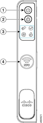
Chassis Health LEDs
The Cisco UCS XE9305 modular system has the following buttons and chassis health LEDs.
|
LED Name |
States |
|
|
1 |
Power button/LED
|
|
|
2 |
System identification
|
|
|
3 |
System health
|
|
|
3 |
Power supply status
|
|
|
3 |
Fan status
|
|
|
3 |
Network link activity
|
|
|
4 |
Near-Field Communication (NFC) Icon
|
Indicates the location to connect NFC devices. |
Power Supplies
The Cisco UCS XE9305 Modular System has two 2400W Titanium rated AC PSUs (UCSXE-PSU-2400W). PSUs are hot swappable and support N+N (Grid) and non-redundant modes. Each PSU is accessible directly from the front of the chassis and is hot-swappable.
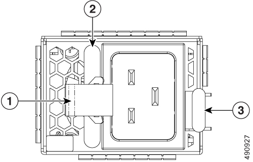
|
1 |
Flexible power cord cable tie |
2 |
PSU handle |
|
3 |
PSU release tab (ejector button) |
- |
Fan Module
The Cisco UCS XE9305 support 5 fans in the chassis rear panel.
Each fan module supports optimizing cooling controls. Each fan module is hot-swappable and can be replaced from both the top and the rear of the chassis.

|
1 |
Fan module locking release buttons, two. Both must be pressed to remove the fan module. |
2 |
Fan module handle. |
Security Bezel
The Cisco UCS XE9305 Modular System supports an optional locking bezel (UCSXE-BEZ-3) that Fattaches to the front panel. The bezel is installed between the chassis front mounting brackets (latches) and prevents access to the compute nodes, PSUs, and cabling.
To provide additional physical security for the chassis, keys are associated with the bezel to enable locking the bezel to prevent its removal.
As an option, the interior of the security bezel support two threaded standoffs which can accept an individually mountable air filter to minimize the intrusion of dust and other airborne particulates into the chassis.
Air Filter Assembly
The Cisco UCS XE9305 Modular System supports an optional air filter assembly (UCSXE-BEZ-FLTR) that prevents dust and other particulate contaminants from entering the chassis.
The air filter assembly consists of a frame around which a foam filter is wrapped. The foam filter captures the airborne particles that would normally enter the chassis. The foam filter is replaceable by fitting it into the frame.
Cable management brackets install onto the left and right side and must be oriented the same way to facilitate cable organization at the front of the chassis.
The air filter installs into the interior of the security bezel by two captive thumbscrews (1). After the air filter is attached, installing the bezel provides not only security, but filtration also.
Cisco XE130c M8 1U Compute Node
The Cisco XE9305 modular system supports up to five Cisco XE130c M8 compute nodes. These compute nodes support a mix of network and storage options, including a dedicated slot for an NVIDIA L4 GPU, E3.S NVMe EDSFF drives, and/or a PCIe card in a riser cage expansion slot.
The Cisco X3130c M8 1U compute node offers 12 core (UCSXE-130C-M8-12), 20 core (UCSXE-130C-M8-20), and 32 core versions (UCSXE-130C-M8-32).
Each compute node can feature an optional M.2 boot-optimized M.2 SATA RAID controller. The module supports a variety of SSD capacities, 240G, 480G, or 960G. A single SSD connects to the module, and the module connects to the compute node's PCB through a through a USB 2.0 interface. This M.2 module is used as the boot drive for the compute node. RAID 0/1 and out-of-band management (OOB) are supported.
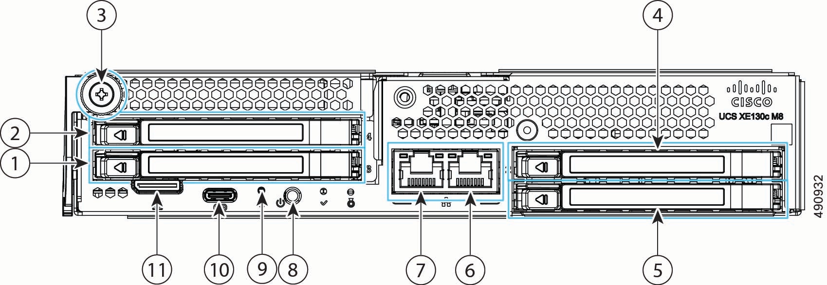
Each compute node features local storage through its E3.S drives. Compute nodes support either a three-drive or four-drive configuration. Drive slot numbering is bottom to top and left to right, so drive 1 is in the bottom slot, and drive 2 is in the top slot.
Four-Drive Compute Node
The four-drive configuration has the following features.
|
1 |
One hot-pluggable E3.S drive, slot 3 |
2 |
One hot-pluggable E3.S drive, slot 4 |
||
|
3 |
Node ejector thumbscrew |
4 |
One hot-pluggable E3.S drive, slot 2 |
||
|
5 |
One hot-pluggable E3.S drive, slot 1 |
6 |
Integrated 10 Gbps RJ-45 host port |
||
|
7 |
Integrated 10 Gbps RJ-45 host port |
8 |
Locator LED/button |
||
| 9 |
Pin-hole Reset button |
10 |
USB-C Console port |
||
|
11 |
UCuLink port
|
- |
Three-Drive Compute Node
The three-drive configuration has the following features.
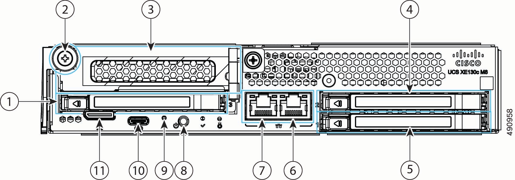
|
1 |
One hot-pluggable E3.S 1T drive, slot 3 |
2 |
Thumbscrew |
||
|
3 |
Optionally, can support either one PCIE Gen5 x4 slot or one additional E3.S drive. When populated with a device, this is slot four. For more information, see Supported PCIe Cards. |
4 |
One hot-pluggable E3.S drive in slot 2. Drive slot numbering is bottom to top and left to right, so drive 1 is in the bottom slot, and drive 2 is in the top slot. |
||
|
5 |
One hot-pluggable E3.S drive in slot 1. |
6 |
Integrated 1/10 Gbps RJ-45 host port |
||
|
7 |
Integrated 1/10 Gbps RJ-45 host port |
8 |
Locator LED/Button |
||
|
9 |
Pin hole reset button |
10 |
USB-C Console port |
||
|
11 |
UCuLink port
|
- |
Compute Node LEDs
Each of the Cisco UCS XE130C M8 compute nodes features the following module indicator LEDs.
|
LED |
Color |
Description |
|---|---|---|
|
Status LEDs
|
Solid Green |
The compute node is operating normally |
|
Blinking Green |
Chassis initialization and memory check |
|
|
Solid Amber |
The compute node is experiencing a non-optimal condition:
|
|
|
Blinking Amber |
The compute node is experiencing a critical condition:
|
|
|
Locator LED/button
|
Off |
Locator function not enabled |
|
Blinking blue, 1 Hz |
Locates a selected compute node—If the LED is not blinking, the compute node is not selected. You can control the LED through either of the following ways:
|
Supported PCIe Cards
The UCS XE130c M8 Compute Node offers customizable PCIe connectivity through a configurage PCIe riser cage that can accept up to one PCIe adapter card, a NIC or an HBA.
The optional PCIe card can be installed on the left side of the node, above slot 3 or in slots 3 and 4 depending on whether the PCIe cage is one slot or two.. The following PCIe cages are supported to complete either a three drive or four drive configuration.
-
Left E3.S 2-Drive Riser Assembly for UCS XE9305 Chassis, four drives (UCSXE-1U-E3S-2L).
-
Left E3.S 2-Drive Riser Assembly for UCS XE9305 Chassis, three drives (UCSXE-1U-E3S-1L). With this configuration a serparate riser (UCSXE-1U-PCI-L) is also required.
Each riser cage can accept one of the following third-party PCIe cards.
|
Card Type |
Card |
Cisco PID |
|---|---|---|
|
NIC |
Cisco-Intel I710-T4L 4x1GBASE-T NIC |
UCSXE-P-IQ1GC |
|
Cisco-Intel X710T2LG 2x10GBE RJ45 PCIe NIC |
UCSXE-P-ID10GC |
|
|
Cisco-Intel X710T4LG 4x10GBE RJ45 PCIe NIC |
UCSXE-P-IQ10GC |
|
|
Cisco-Intel E810XXVDA2 2x25/10GBE SFP28 PCIe NIC |
UCSXE-P-I8D25GF |
|
|
Cisco-Intel E810CQDA2 2x100 GbE QSFP28 PCIe NIC |
UCSXE-P-I8D100GF |
|
|
HBA |
Cisco-QLogic QLE2872 2x 16/32/64GFC Gen 7 Enhanced PCIe HBA |
UCSXE-P-Q7D64GF |
Supported GPUs
Through the use of optional PCI riser cages, each Cisco UCS XE130c M8 Compute Node can be customized to accept up to one GPU.
The riser cage and GPU can be installed on the right side of the node, above slots 1 and 2.
If you order a GPU with your initial shipment, the GPU will be pre-installed, but additional GPUs can be ordered and installed in the field, as your deployment scales out.
The following table shows the model and form factor of GPU supported by the compute node.
|
GPU |
Cisco PID |
|---|---|
|
NVIDIA L4:70W, 24GB, 1-slot HHHL GPU |
UCSXE-GPU-L4 |
UCS Edge Chassis Management Controller
The chassis contains two Chassis Management Controller modules, called the Edge Chassis Management Controllers (eCMC) which support the interface from the chassis to the rest of the network through uplink ports. The two eCMC modules operate as a pair.
-
One module is the primary, which is online and active.
-
The other module is the secondary, which is a warm standby to ensure continuous operation of the chassis in the unlikely event that the chassis experiences a switchover event.
The eCMC modules are assigned dedicated slots in the chassis. They must always be installed in those slots.
The online primary module manages the chassis and computing nodes. It also supports the connection to UCS Intersight management software. Also, eCMC functions as switch for data traffic from different computing nodes.
Each eCMC module can feature an optional M.2 boot-optimized M.2 module. The module supports a single 75 GB M.2 SSD (UCSXE-ECMC-M2-75G). The SSD connects to the module, and the module connects to the eCMC PCB through a through a USB 2.0 interface. This M.2 module provides local storage to support parallel compute OS installation through visual media. The eCMC can be ordered with the M.2 SSD installed (UCSXE-ECMC-M2-75G) or without (UCSXE-ECMC-G1).
Each eCMC module has the following hardware features.

|
1 |
Module status LEDs. |
2 |
RJ-45 Ethernet Management port |
|
3 |
Ejector handle, which unlocks the module for hot-swap |
4 |
Ejector |
|
5 |
1/10G SFP+ Network uplink port, two |
6 |
1/10G SFP+ Network uplink port, one |
|
7 |
SFP+ port LEDs |
8 |
USB-C Console port |
|
9 |
Reset Button Behavior depends on how long you press.
|
10 |
USB-C port |
Edge Chassis Management Controller LEDs
Each eCMC module has module status LEDs and port status LEDs.
|
LED |
Color |
Description |
|---|---|---|
|
Status LEDs
|
Off |
The eCMC is not powered on |
|
Green (Solid) |
Normal operation |
|
|
Amber (Solid) |
The eCMC is in a Degraded operational state, for example:
|
|
|
Amber (Blinking) |
The eCMC is booting up, or if the eCMC has booted to runtime, it is in a Critical operational state, for example:
|
|
|
Locator LED/Button
|
Off |
The eCMC Locator is not currently active. |
|
Blinking (Blue) |
Locates a selected eCMC. If the LED is not blinking, the eCMC is not selected. You can initiate the LED in UCS Intersight. |
|
|
Primary/Secondary LED |
Off |
Dark, no color |
|
Green |
Primary |
|
|
Blinking Green |
Secondary |
|
LED |
Color |
Description |
|---|---|---|
|
Link/Activity (Left LED) |
Off |
No Link Detected |
|
Solid Green |
Link Detected |
|
|
Blinking Green |
Transmitting or Receiving Data Traffic |
|
|
Blinking Amber |
Software-defined errors detected |
|
|
Speed (Right LED) |
Off |
No traffic detected |
|
Solid Green |
Maximum speed detected |
Summary of Features
The Cisco UCS XE9305 modular system has the following main features.
-
RU-high, 19-inch wide and 18-inch deep chassis with 5 front-facing flexible slots for compute nodes.
-
Two (2) hot-swappable eCMCs forming a unified fabric that provide connectivity between all nodes within the chassis and with upstream networks, and provide local chassis management and secure control plane connection with Cisco Intersight. Each CMC features:
-
An embedded 25 Gbps switch with 145 Gbps of switching bandwidth with five (5) rear-facing 25 Gbps switch ports connecting to nodes within the chassis through the chassis mid-plane and two (2) front-panel 10 Gbps SFP+ uplink ports for data traffic
-
One (1) front-panel 1 Gbps RJ45 uplink port for management traffic
-
Two (2) front-panel USB-C ports for management console and external storage connectivity
-
-
Two (2) hot-swappable 2400W Titanium AC Power Supply Units (PSUs) providing N+N redundancy, removable from the front for service by a latching mechanism without special tooling.
-
Five (5) 80 mm by 56 mm hot-swappable fan modules with acoustically optimizing cooling controls, removable from both the top and the rear for service by a latching mechanism without special tooling.
-
Near Field Communication (NFC) capability embedded in the chassis to aid chassis identification, claiming, and troubleshooting when used in conjunction with the Cisco Intersight app.
-
One (1) optional locking security bezel with separately replaceable air filter covering the entire front of the chassis, providing protection against physical tampering and filtration against ambient particulate matter
-
Additional accessories to fit your deployment:
-
sliding rail kit for installation and maintenance in 4-post racks
-
static mount kit for 2-post racks
-
brackets for horizontal or vertical mountng on flat surfaces, such as shelves and tabletops
-
 Feedback