Servicing the Chassis
The Cisco UC XE9305 Modular System has field-serviceable components at the chassis, node, and component scope.
|
Scope |
Serviceable Item |
|---|---|
|
Chassis (UCSXE-9305=) |
|
|
Nodes |
|
To perform field-service tasks for this hardware, use the tasks in this chapter.
Safety Considerations for Field-Serviceable Components
Take note of the following for servicing field-replaceable components:
-

Warning
This unit might have more than one power supply connection. To reduce risk of electric shock, remove all connections to de-energize the unit.

-
Warning
There are no serviceable parts inside. To avoid risk of electric shock, do not open.
-

Note
An instructed person is someone who has been instructed and trained by a skilled person and takes the necessary precautions when working with equipment.
A skilled person or qualified personnel is someone who has training or experience in the equipment technology and understands potential hazards when working with equipment.
-
Warning
Only a skilled person should be allowed to install, replace, or service this equipment. See statement 1089 for the definition of a skilled person.
-
Warning
Only an instructed person or skilled person should be allowed to install, replace, or service this equipment. See statement 1089 for the definition of an instructed or skilled person.
Service Restrictions and Guidelines
In addition to these restrictions and guidelines, see Safety Considerations for Field-Serviceable Components.
The following notes and warnings apply to all installation tasks:
 Caution |
Parts such as PSUs and eCMCs can be removed to lessen the overall chassis weight before performing field service procedures. However, even with parts removed, the chassis still has considerable weight. Make sure to use a scissors jack, server lift, or other machinery to bear the weight of the chassis during installation. |
Warning |
IMPORTANT SAFETY INSTRUCTIONS This warning symbol means danger. You are in a situation that could cause bodily injury. Before you work on any equipment, be aware of the hazards involved with electrical circuitry and be familiar with standard practices for preventing accidents. Use the statement number provided at the end of each warning to locate its translation in the translated safety warnings that accompanied this device. Statement 1071 SAVE THESE INSTRUCTIONS |
Important |
Watch your hands and fingers whenever you handle the chassis, compute nodes, and other components! Narrow vertical or horizontal spaces in situations like, but not limited to, moving the chassis into or out of the shipping container or equipment rack can cause pinch hazards for your hands and fingers. |
Serviceable Components
The Cisco UCS XE9305 Chassis has field-serviceable components on the eCMC and the compute nodes.
In addition to these board-level components, fans and power supplies are serviceable.
Compute Node Serviceable Components
The compute nodes have the following serviceable components.
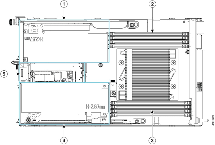
Note |
The compute node CPU is not field-replaceable. If you need service or an upgrade, you must order a new compute node. |
|
1 |
PCI Riser 1 |
2 |
Top DIMM bank |
|
3 |
Bottom DIMM bank |
4 |
PCI Riser 2 |
|
5 |
M.2 Module |
- |
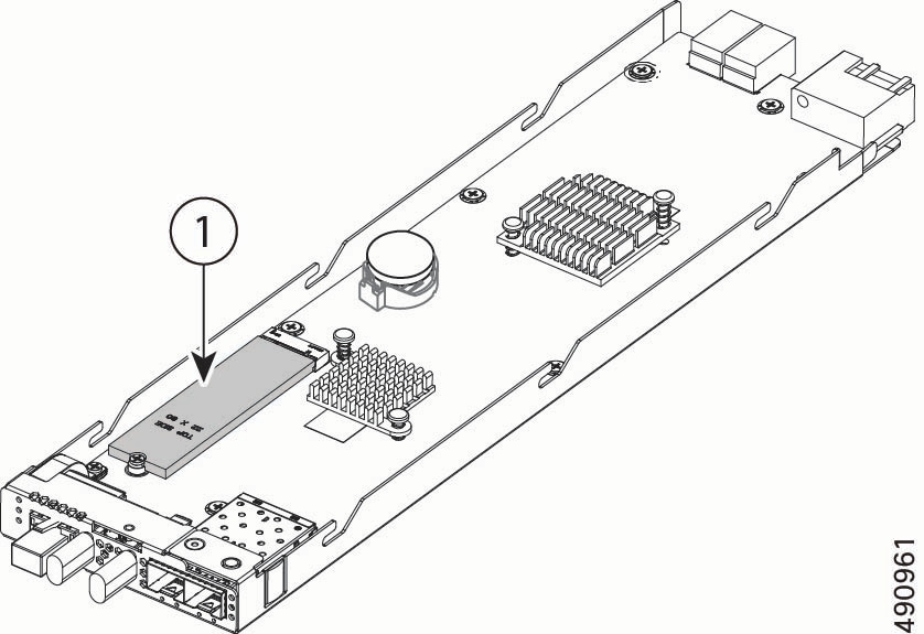
Chassis Management Controller Serviceable Components
The chassis management controller (eCMC) module contains the following serviceable component.
|
1 |
Boot-Optimized M.2 Module, consisting of one M.2 SSD and a carrier. |
- |
- |
Replacing a Node Top Cover
Each node in the chassis has a sheet metal top cover to protect components and provide optimal airflow. The top cover must be removed to access any field-serviceable components.
The top cover is held in place by the following features:
-
Release button that locks and unlocks the latch for the top cover.
-
Alignment pins that insert into grooves on the top of the node. The pins enable easy installation and removal of the top cover as well as securing the top cover.
To replace the node top cover, use the following tasks.
Removing a Node Top Cover
Use this task to remove the node top cover.
Before you begin
To access the node top cover, the node must be removed from the chassis. When the node is removed from the chassis, the node is disconnected from the power backplane, so the node is powered off.
Procedure
|
Step 1 |
Press the release button on the node top cover. |
|
Step 2 |
While holding the release button down, slide the top cover toward the back of the node and lift the back end up to enable the retention pins to clear the grooves on the top of the node. 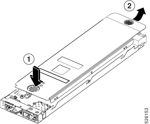 |
Installing a Node Top Cover
Use this task to install a node top cover.
Before you begin
After any service procedures are complete, you must install the node top cover before re-installing it into the chassis.
When the node is re-installed, it will power on after successfully connecting to the power backplane.
Procedure
|
Step 1 |
Lower the top cover onto the node. |
|
Step 2 |
Slide the front end of the top cover under the sheet metal edge on the node, while making sure that the retention pins slide into the grooves on the top of the node. 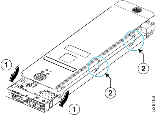 |
|
Step 3 |
Continue sliding the top cover until the release button engages to indicate that the top cover is locked. |
Replacing the Security Bezel
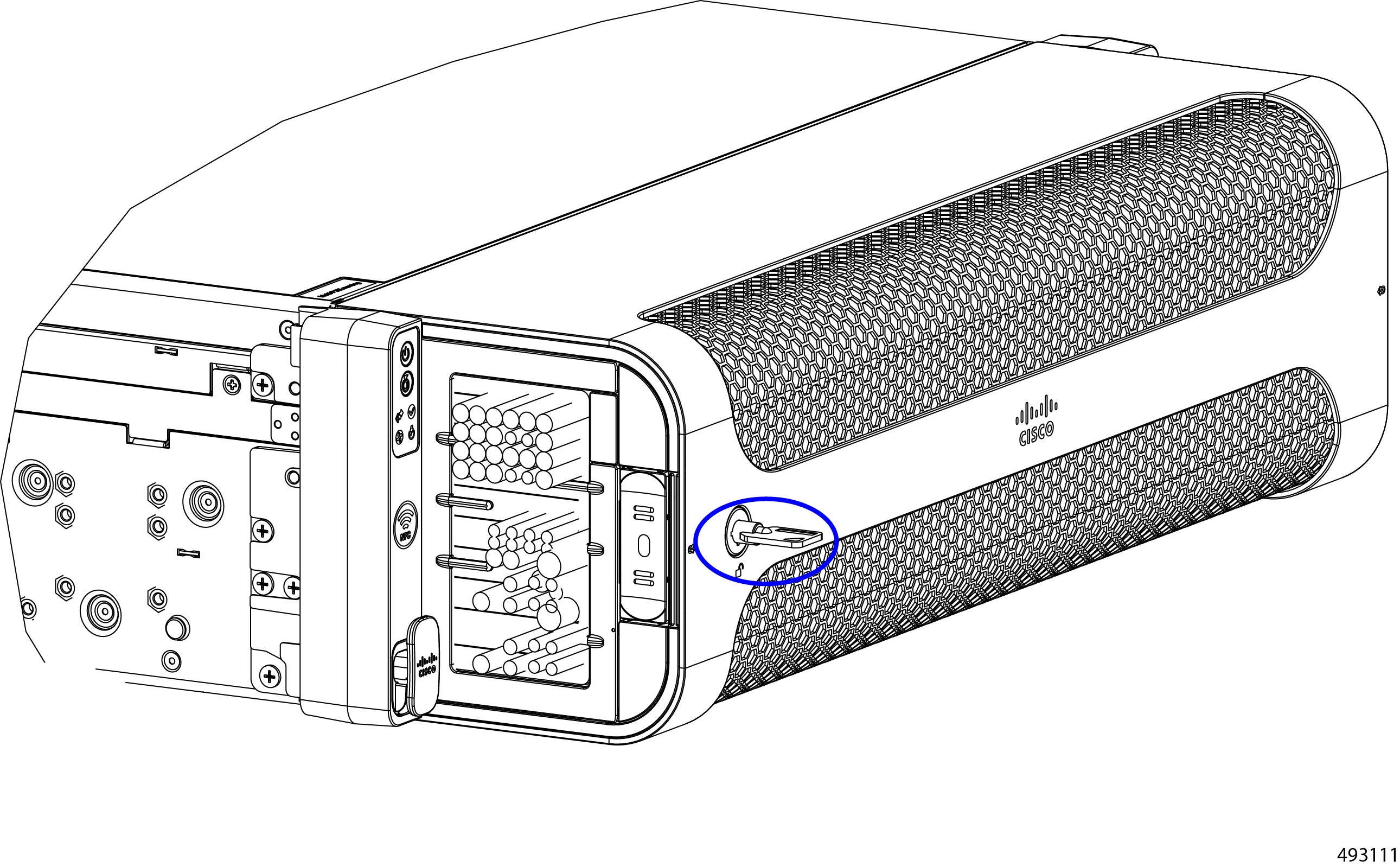
The chassis features a front bezel (UCSXE-BEZ-3). To provide security, the bezel locks and unlocks with a paired set of keys that fit into the key slot on the face of the security bezel.
To provide the highest physical security, we recommend leaving the bezel attached and locked, and keep the keys in a secure place. These recommendations are in addition to any other physical security you use, such as keeping the XE9305 chassis in locked or access-controlled room, in a locked datacenter cage, and so on.
When the bezel is installed correctly, the lock is on the left of the bezel's faceplate. The lock moves in a 90° arc between the unlocked and locked position.
-
To lock the bezel, insert the key and turn it to the right until the key is horizontal.
-
To unlock the bezel, insert they key and turn it to the left until the key is vertical.
The security bezel also supports two cable management assemblies for efficient cable routing and an air filter that helps reduce airborne particulate matter. The cable management assemblies are considered part of the security bezel, but the air filter is a separately orderable part. Both the air filter and the cable management assemblies mount install into the security bezel. For information about replacing the air filter, see Replacing the Air Filter Assembly.
To install and remove the security bezel, use these tasks.
Removing the Security Bezel
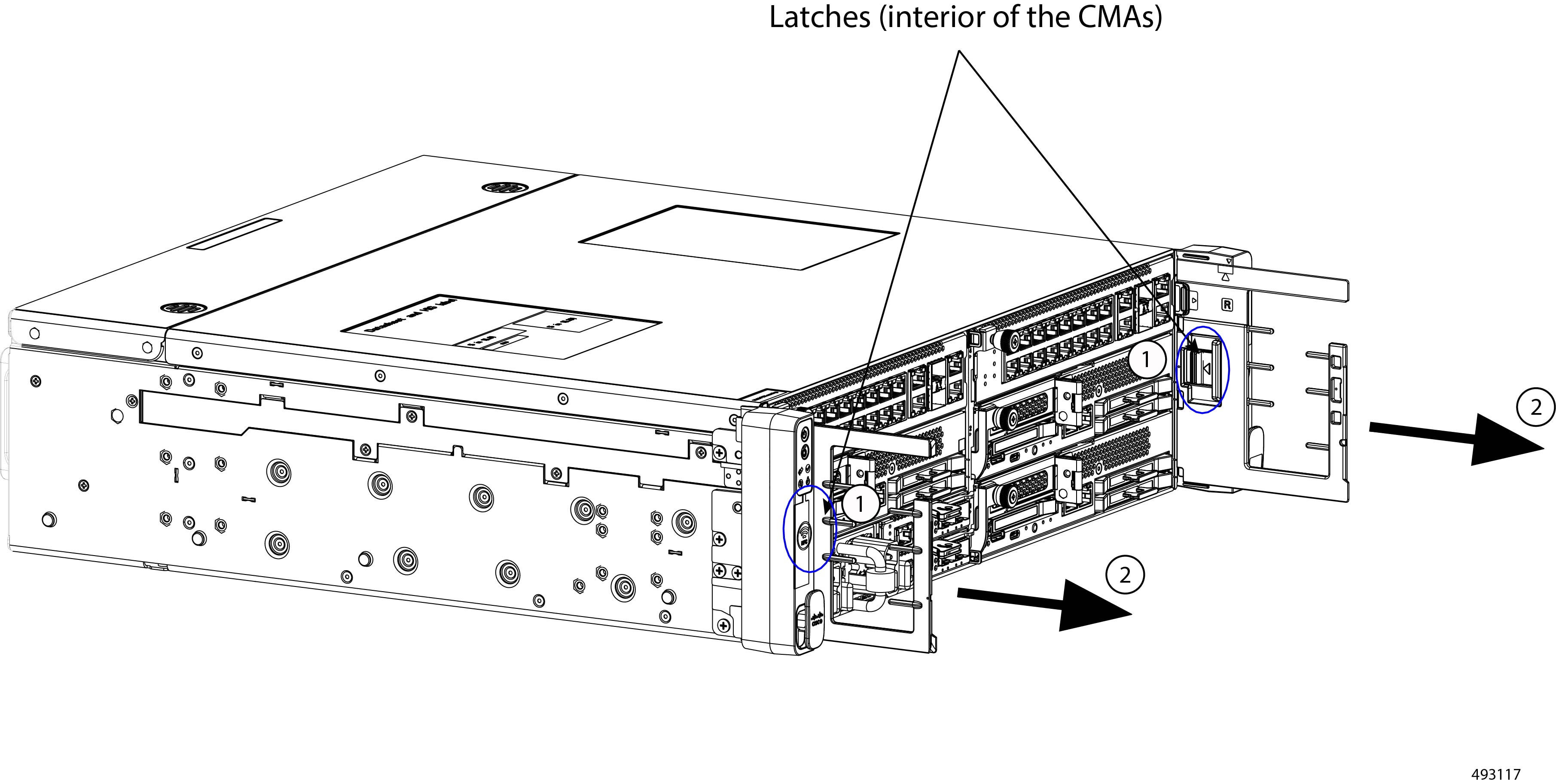
The security bezel contains two cable management assemblies that gather and organize cables connected to the chassis. As part of removing the security bezel, you can remove the cable management assemblies by pressing and holding the release latch on the interior of each CMA.
Use this procedure to unlock and remove the security bezel and the cable management assemblies.
Before you begin
If you do not have the keys for the bezel, gather them now.
Procedure
|
Step 1 |
Assuming the bezel is locked, unlock it by inserting the key and turning it 90° counter clockwise to the unlocked position. |
||
|
Step 2 |
Locate and simultaneously press and hold both release buttons on the left and right exterior sides of the bezel.
|
||
|
Step 3 |
Holding the bezel level, pull it straight towards you to detach it from the chassis front panel.
Make sure not to let the bezel fall. |
||
|
Step 4 |
To remove the cable management assemblies:
|
||
|
Step 5 |
As an option, you can service the air filter while the bezel is removed. If you want to service the air filter, see Replacing the Air Filter Assembly. |
Installing the Security Bezel
The chassis has a locking security bezel that installs onto the front panel. The bezel attaches to the front panel by a pressure fit. Through the use of the associated keys, the bezel can be locked to secure the Cisco UCS X9305 chassis, its PSUs, and cable connections.
As part of the security bezel, the cable management assemblies (CMAs) can be installed for efficient cable routing. The CMAs, both left and right sides, attach to the mounting brackets (called "ears" for this procedure) on the chassis and the security bezel so that cable connections to the chassis are also secured within the bezel. The following procedure assumes that the CMAs will be attached.
Installing the bezel is a tool-less procedure. To install the bezel, use this task.
Before you begin
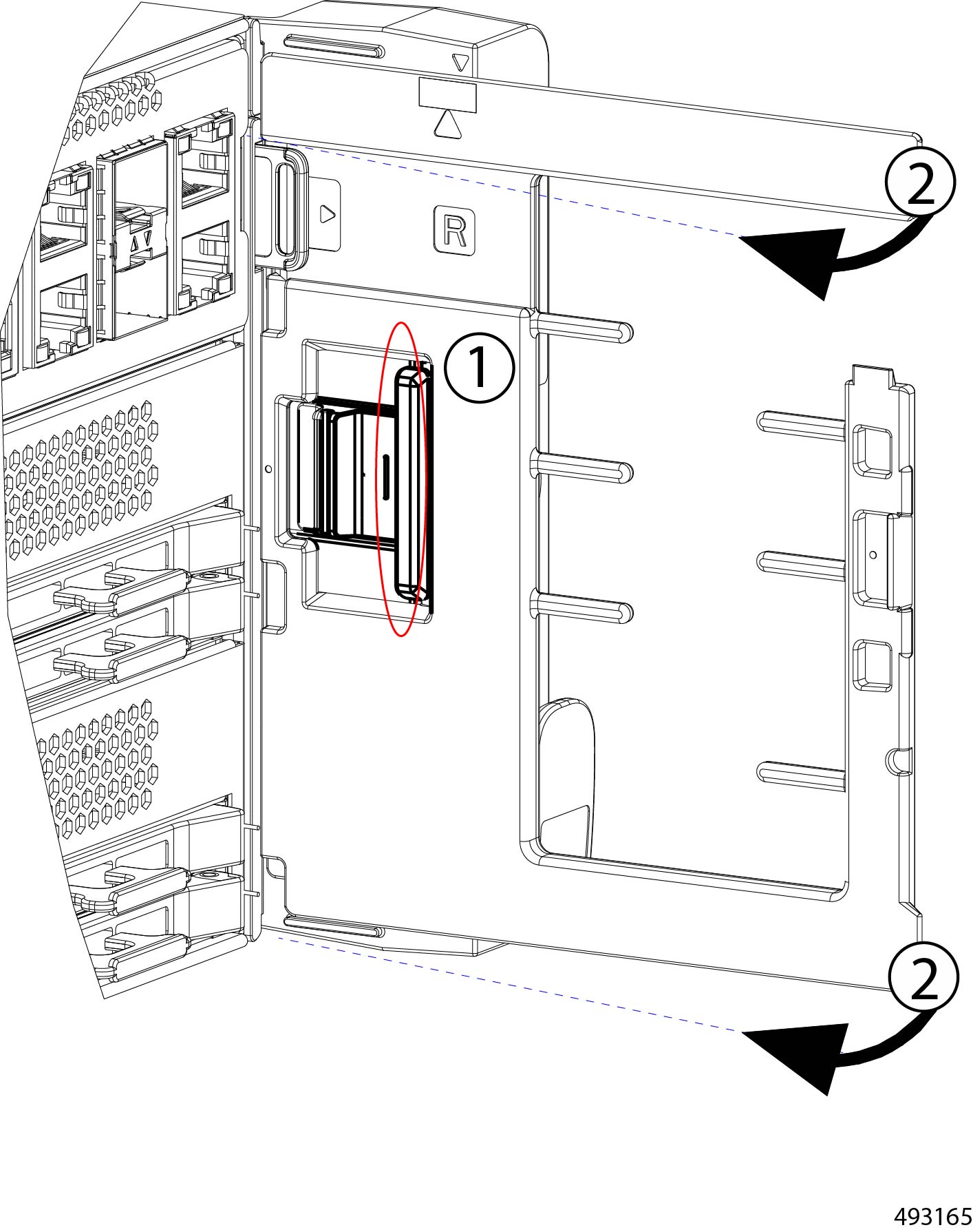
The security bezel's latches accept two cable management assemblies (CMAs), one per side. The CMAs are specific to each side, so they are marked with L for the left side CMA and R for the right-side CMA.
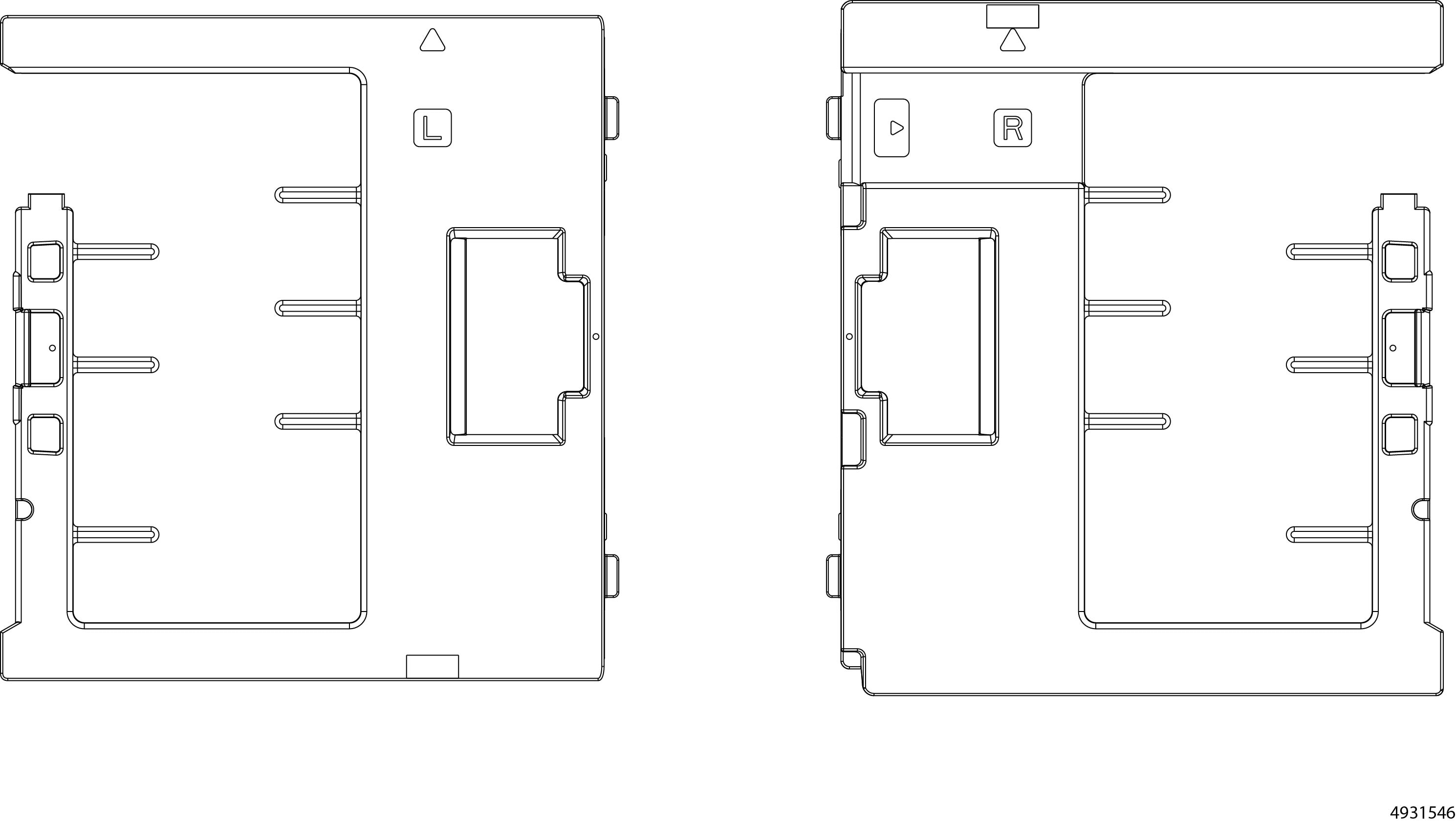
Before beginning this procedure, make sure that you have identified each CMA. During this procedure, you must install the correct CMA on the correct side.
Each CMA has horizontal pegs that help to vertically organize cables into bottom, middle, and top tiers.
Procedure
|
Step 1 |
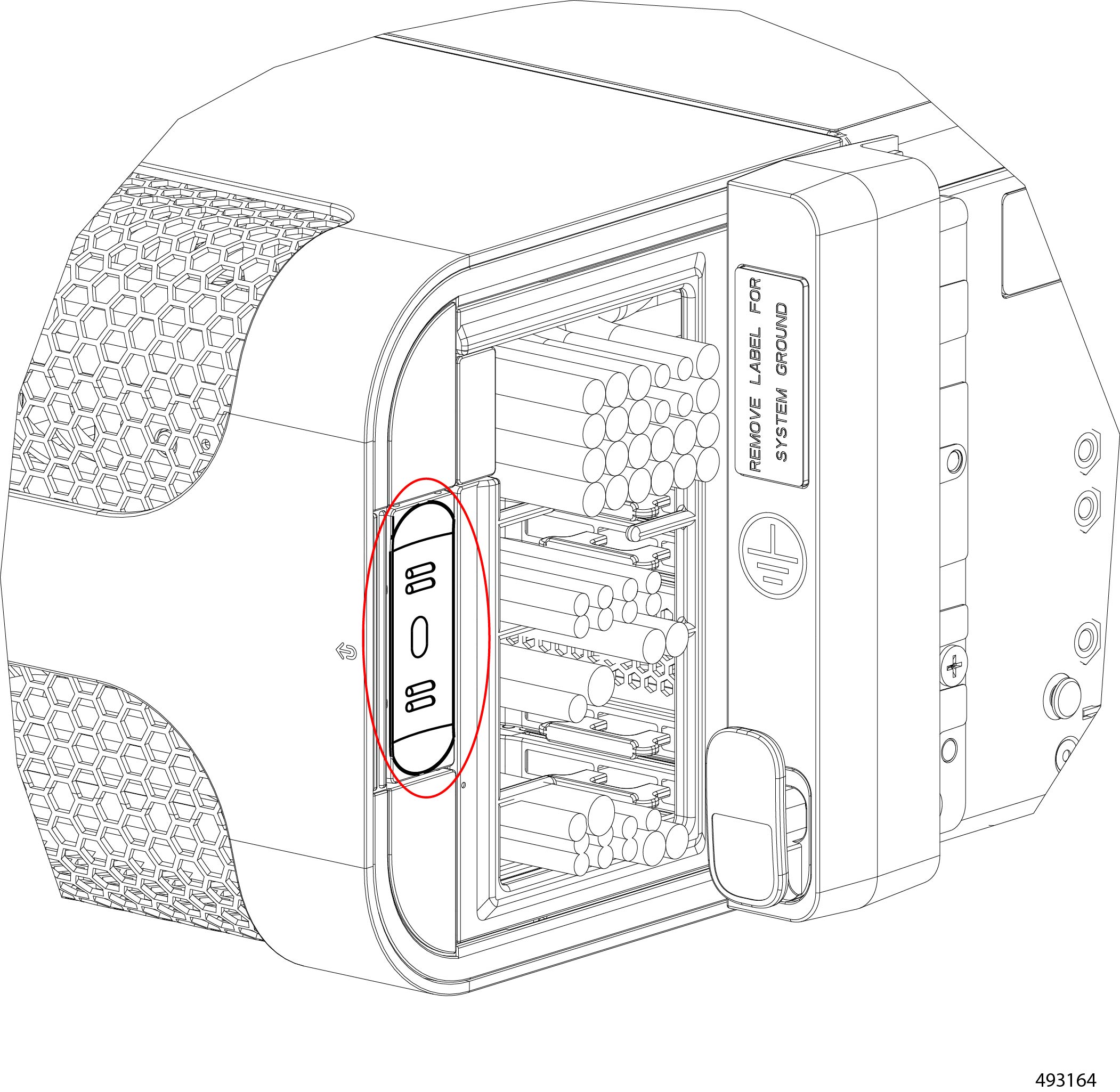
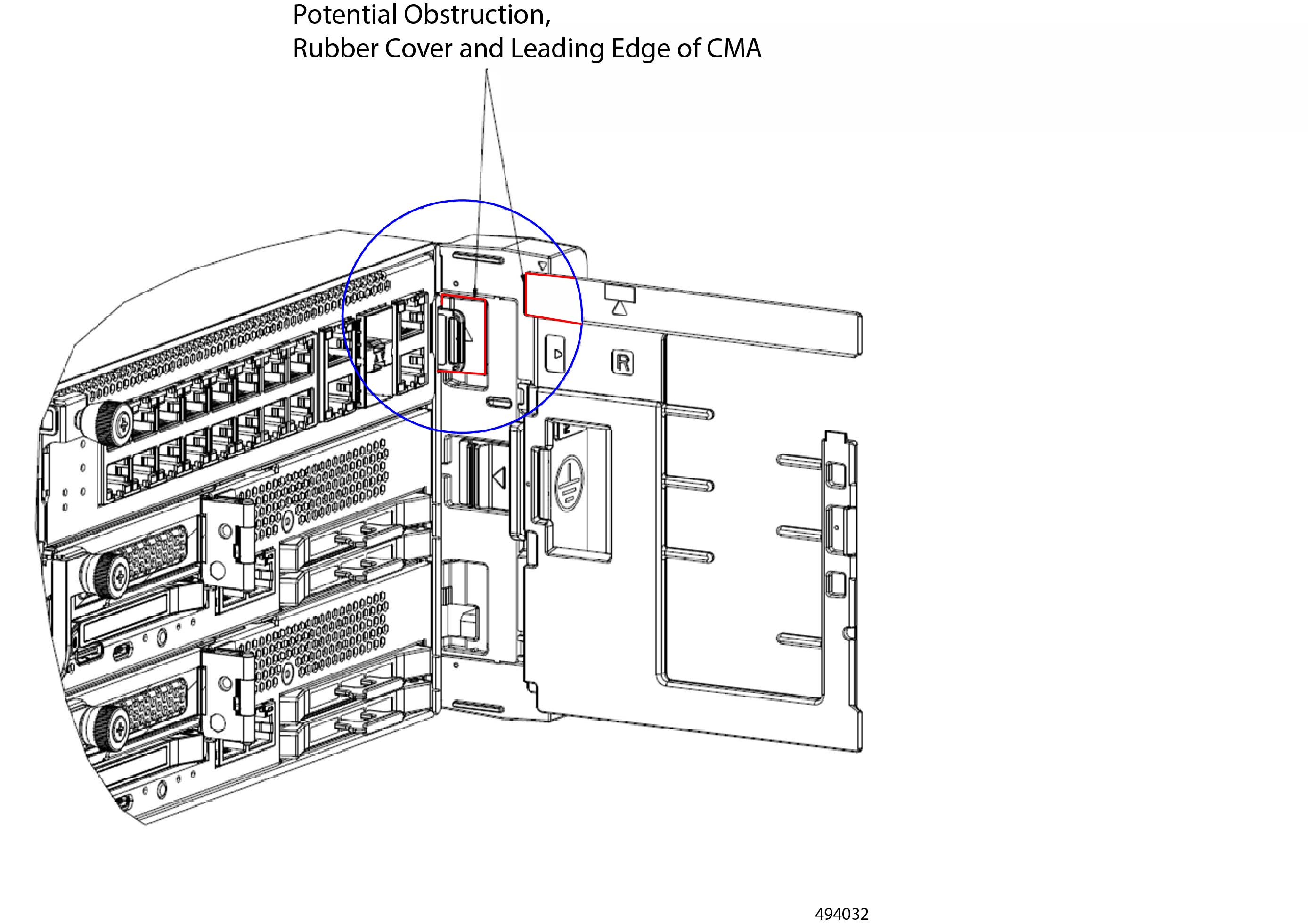
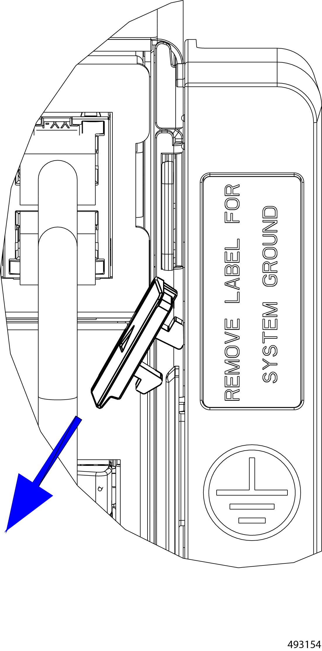
Locate the rubber cover on the right ear.
The rubber cover is located on the interior of the right ear.
|
||
|
Step 2 |
On the right mounting ear, remove the rubber cover. This rubber cover is on the right mounting ear only.
Although you have not installed the CMA yet, when the cover is removed, the connecting parts on the right ear can meet the connecting parts on the CMA when the rubber cover is removed. 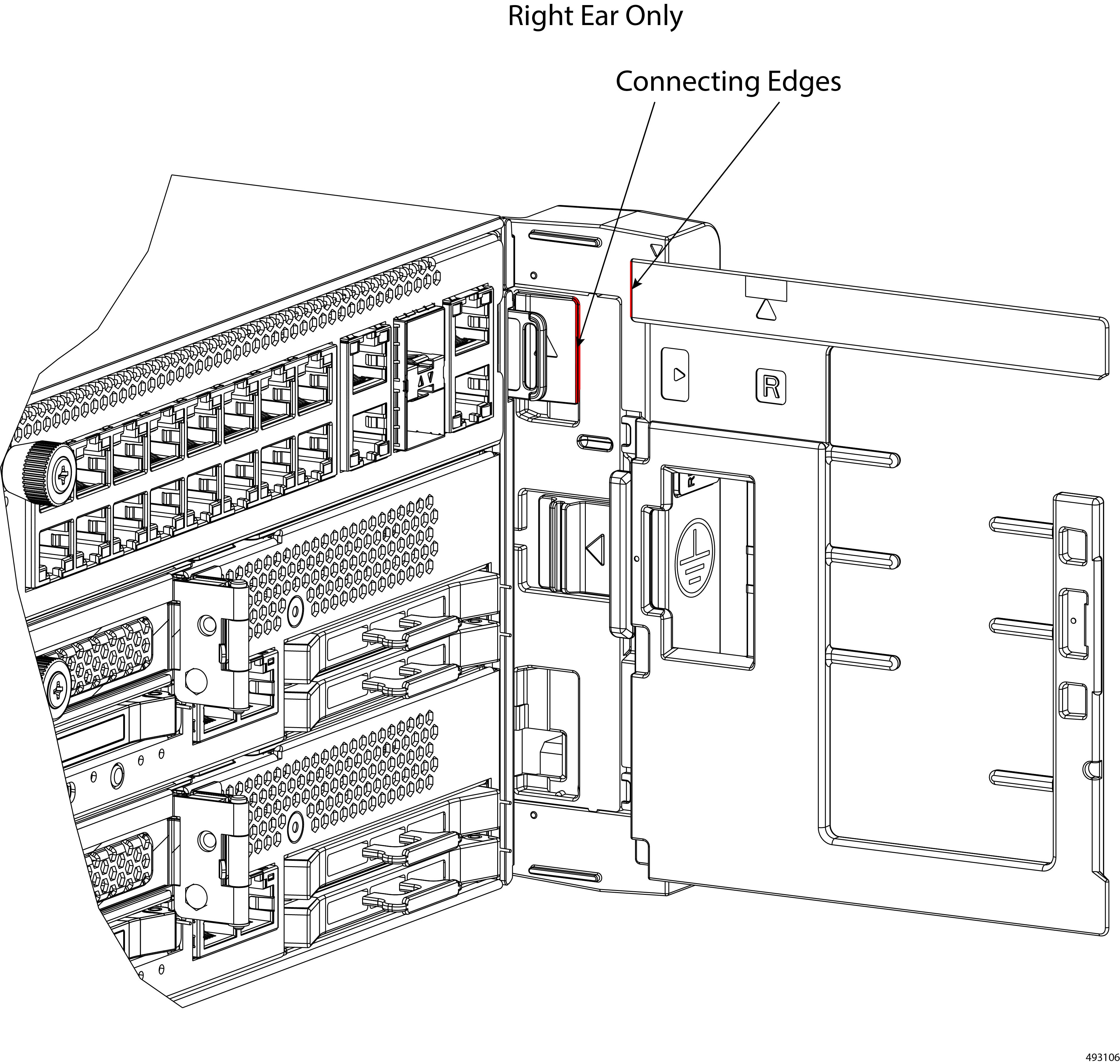 |
||
|
Step 3 |
Install the CMAs on both sides of the chassis.
|
||
|
Step 4 |
Attach and organize cables.
|
||
|
Step 5 |
Install the security bezel.
|
||
|
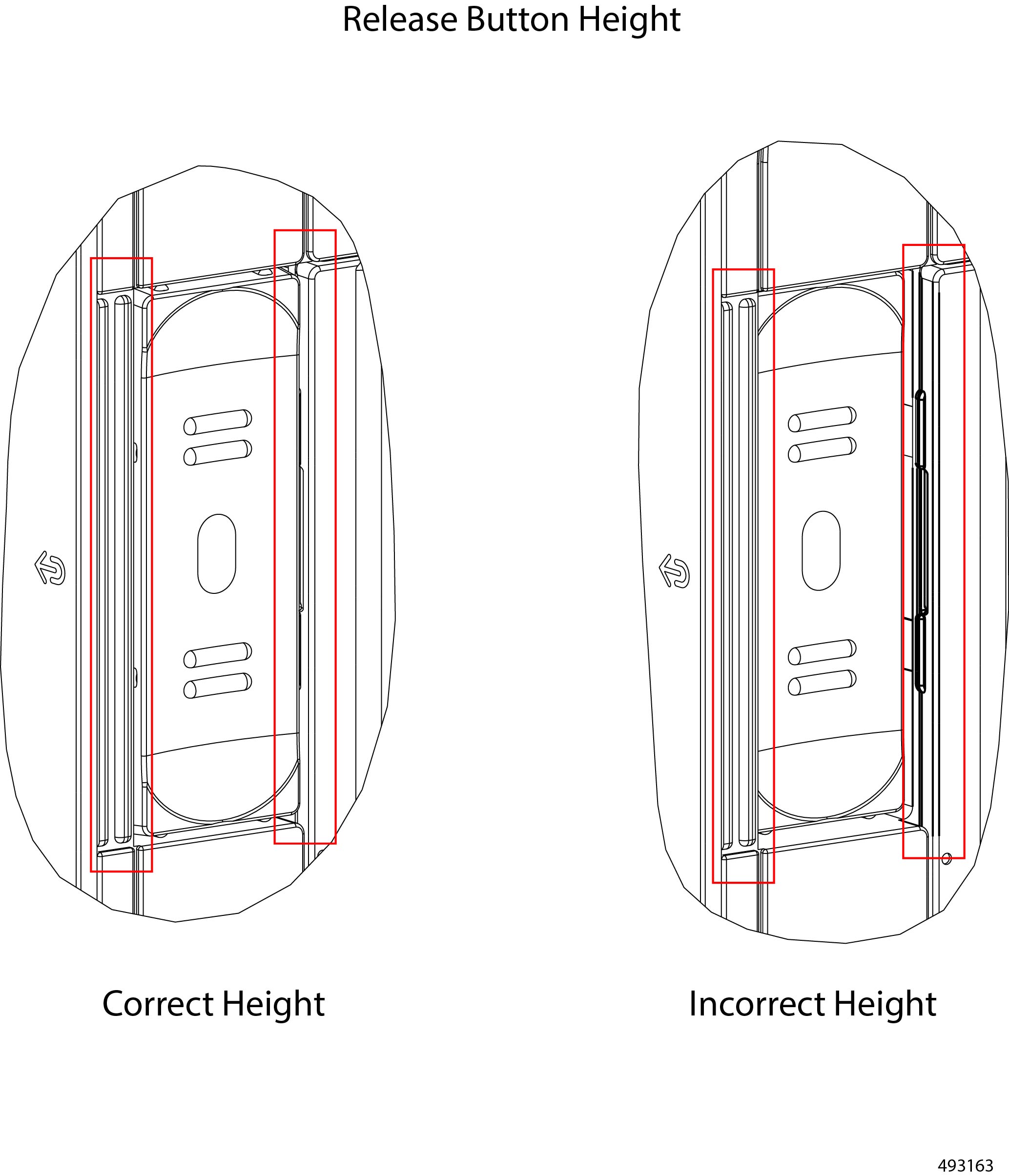
Step 6 |
Inspect the release buttons, which pop up when the bezel is correctly installed. When it is correctly installed, the bezel sits flush against the front of the chassis, and the release buttons sit flush against their frame on each side. If one or both of the bezel's release buttons are recessed (not flush with the frame), the bezel is not correctly installed. After visually inspecting the buttons, you might find it helpful to trace your finger around the edge of the buttons to feel if one, or both, of them is flush or recessed.
|
||
|
Step 7 |
(Optional) Lock the bezel.
|
Replacing the Air Filter Assembly
The chassis has an air filter assembly (UCSXE-BEZ-FLTR) that fits inside the security bezel. The air filter assembly consists of a separate frame that accepts a fine-mesh foam filter that intercepts the majority of airborne particulate matter. The foam filter is held in place by a bracket on the air filter frame, and that frame is attached to the bezel by two captive screws.
The air filter assembly contains a separate foam filter (UCSXE-FLTR-FOAM=) which is a separately replaceable part. The foam filter should be replaced at regular, recommended intervals to protect the chassis from dust and other airborne contaminants.
The air filter assembly is not required to operate the chassis or use the bezel. Although not required, the air filter is highly recommended.
To install and remove the air filter assembly, use the following tasks.
Guidelines and Considerations for the Foam Filter
The chassis air filtration system features a foam filter that fits onto the air filter assembly. The foam filter is a replaceable part.
Be aware of the following guidelines and considerations for the foam filter.
-
General Guidelines:
-
Replacement of the filter is dependent on many factors such as the chassis installation location, amount airborne particulates, and so on. It is recommended that filters be replaced every three to six months, or within the recommended preventive maintenance schedule.
-
Cleaning the filter is not recommended. Instead, it is recommended to replace filters when the recommended hours of service are reached. Replacing filters helps maintain efficient performance of the system.
-
-
Storage Guidelines: Storing filters for longer than a few months is not recommend. Instead, purchasing a smaller number of filters and storing them for only a few months is recommended.
Air Filter Assembly Alignment Considerations
Cable Insertion into the Air Filter Assembly
The air filter assembly consists of a foam air filter and the air filter frame. The entire air filter assembly installs inside the security bezel, which attaches to the chassis through the cable management assemblies (CMAs).
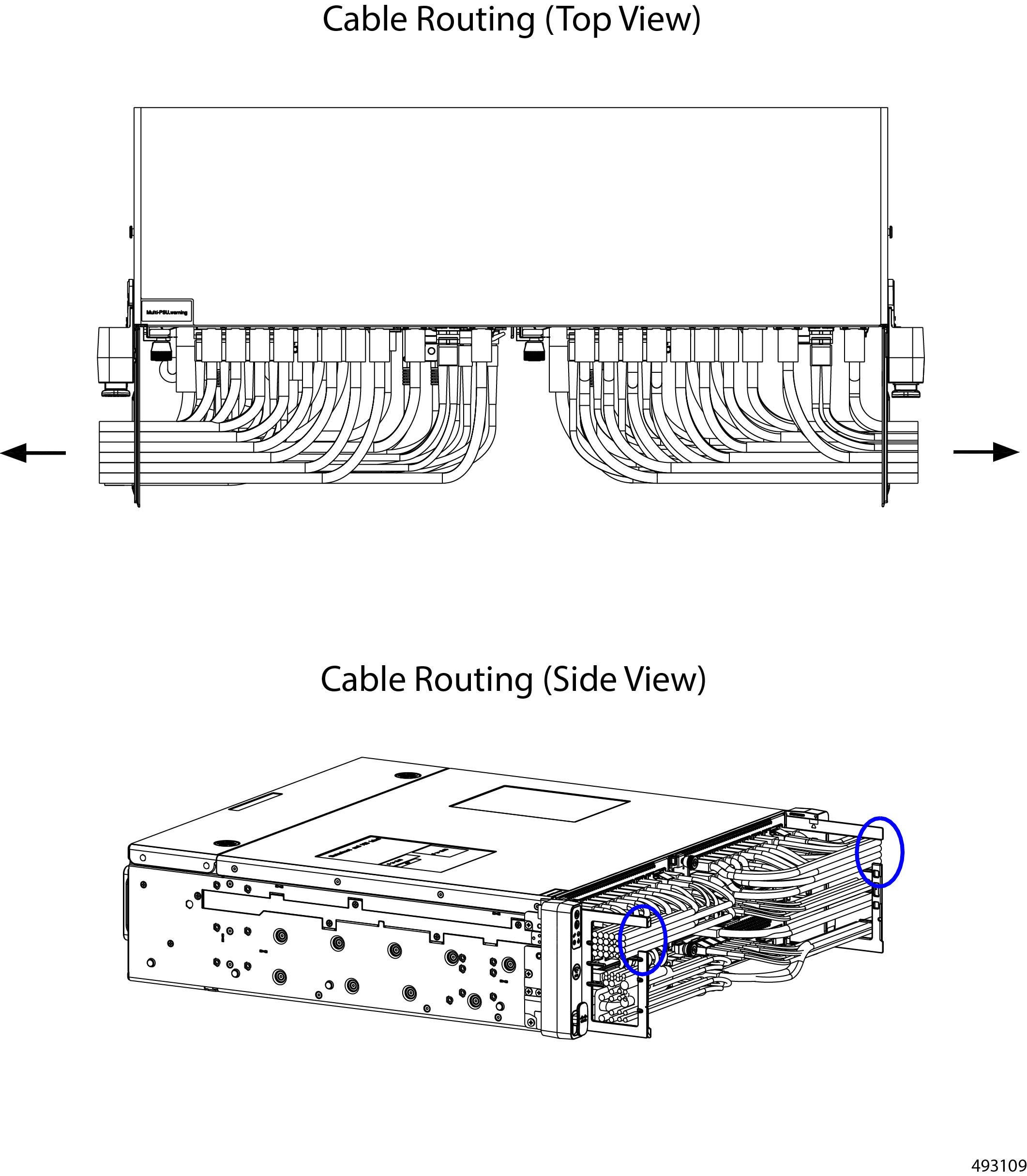
The air filter has corresponding slots, or empty spaces, into which each row of cable must be inserted. Each slot on the air filter assembly maps 1:1 with a row of cables, so each row of cables inserts into the corresponding slot in the side of the air filter assembly.
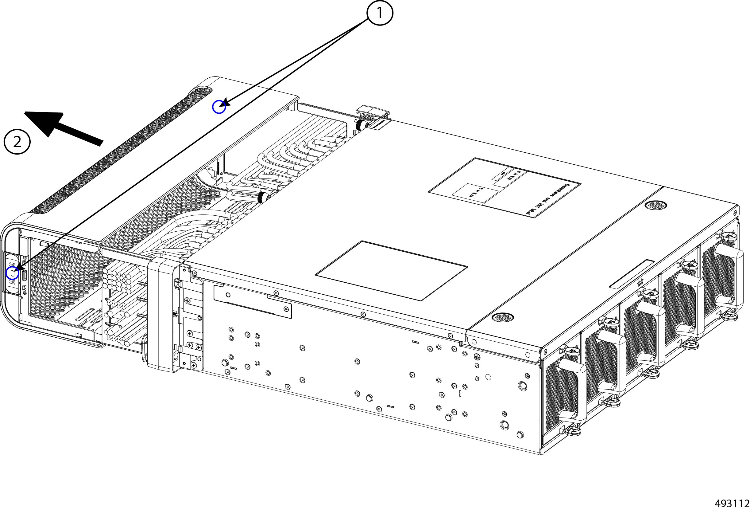
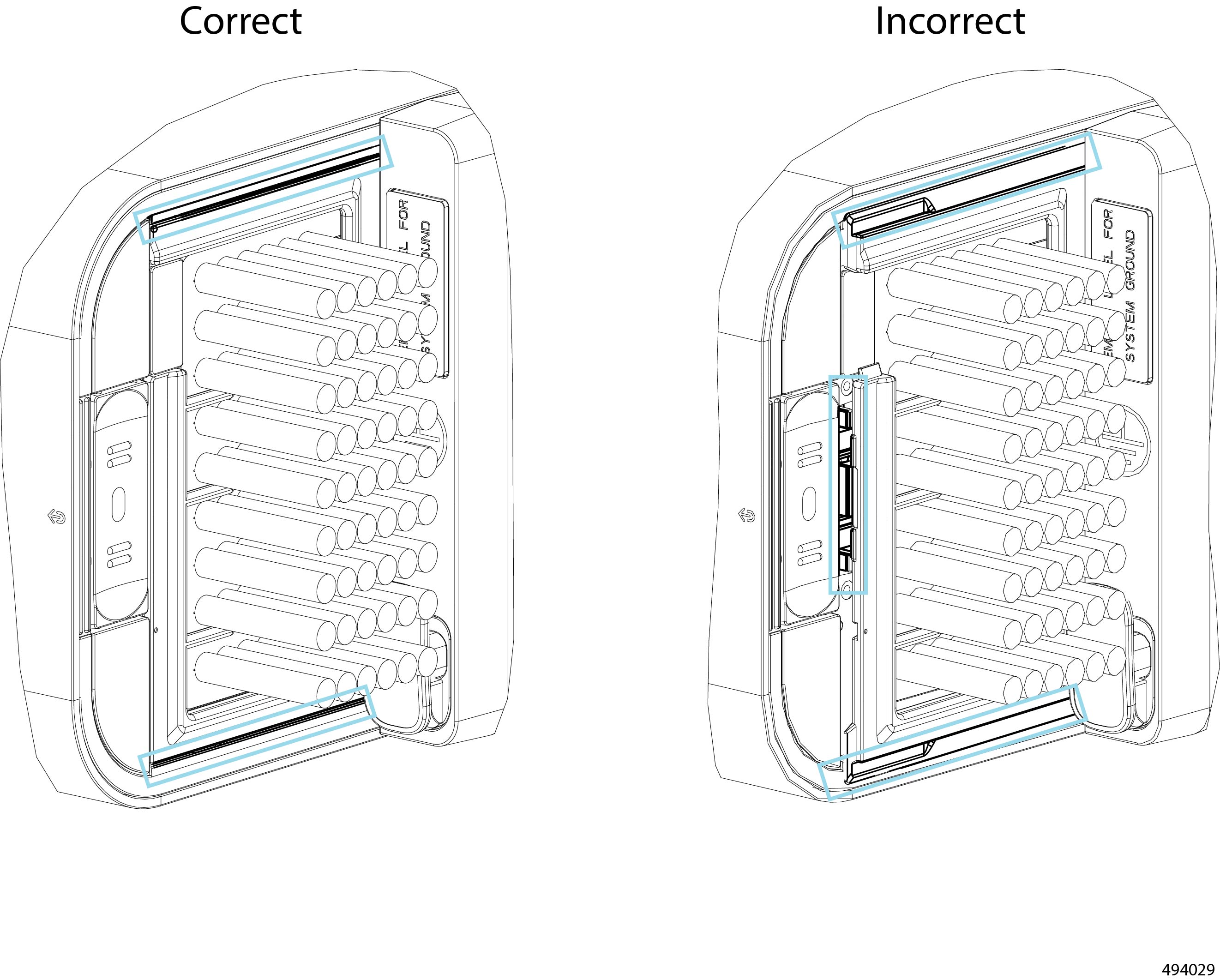
Refer to the following illustration which represents cables correctly installed in their slots as solid circles, and the cables that are still aligning with the correct slot as empty circles.
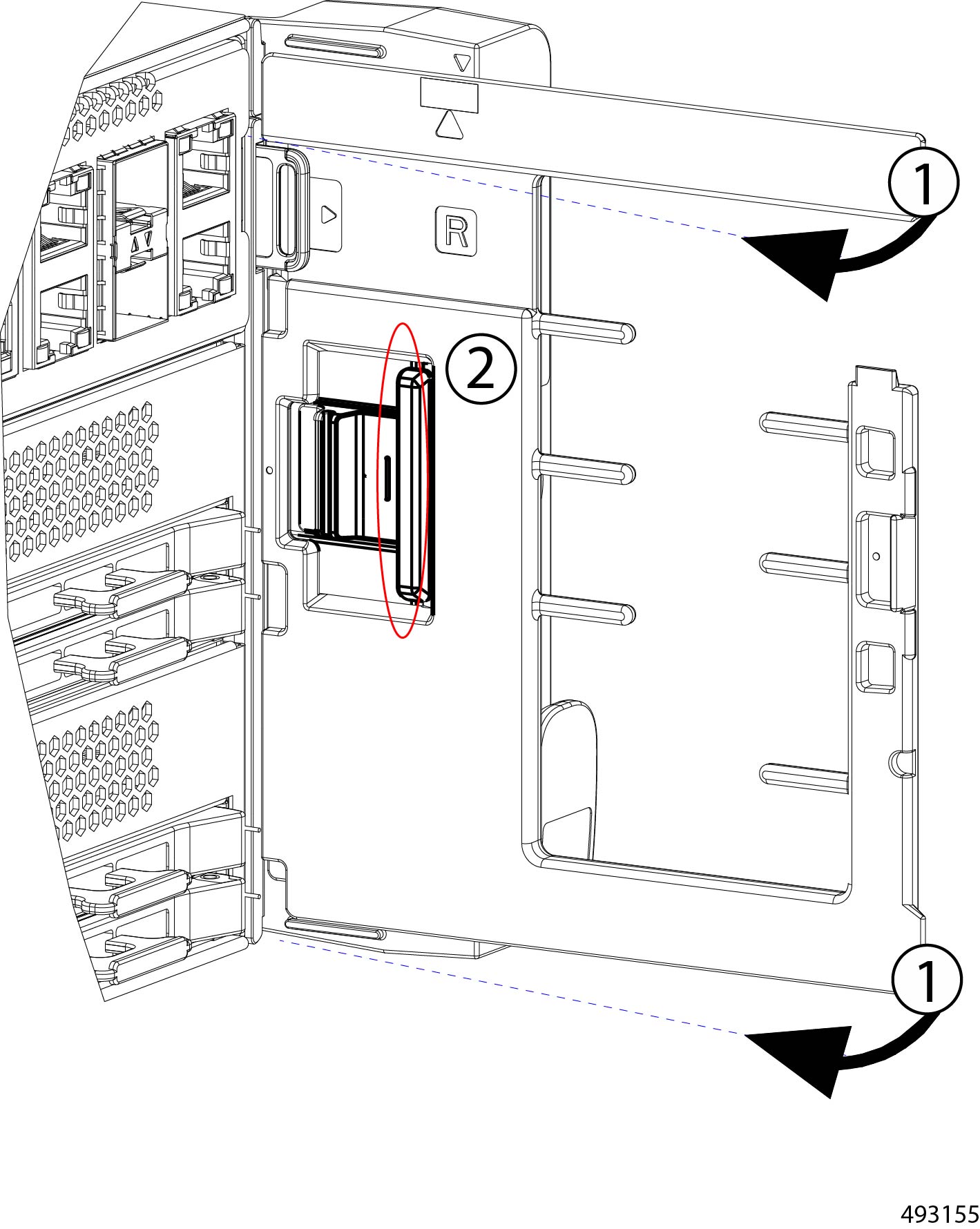
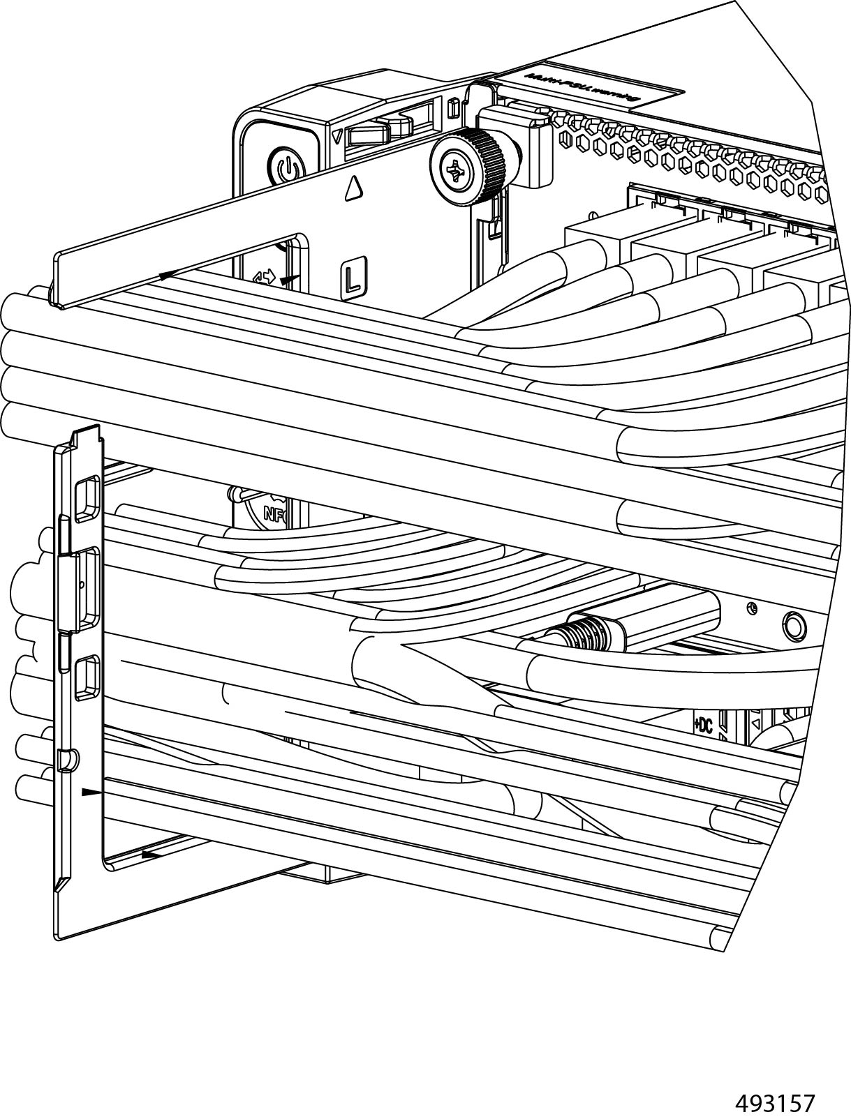
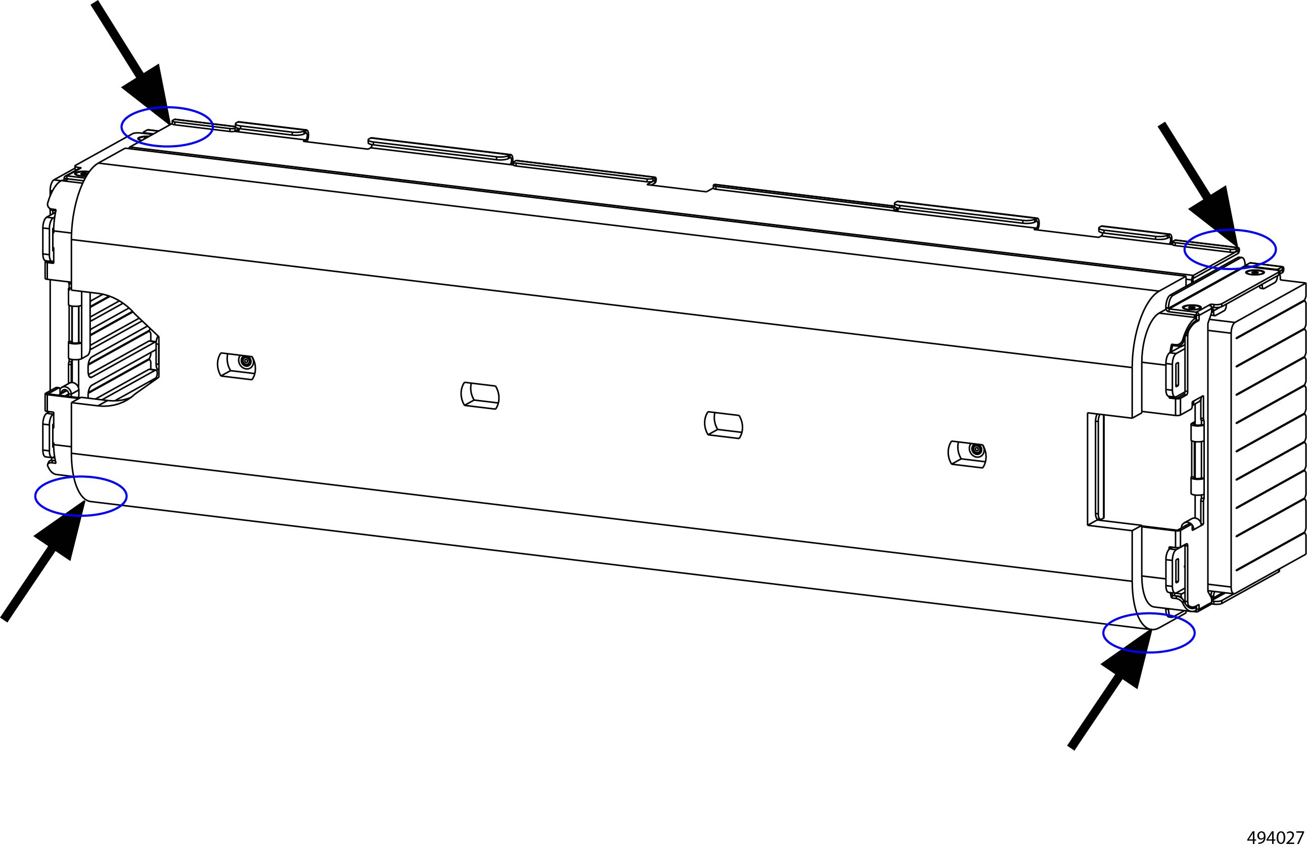
When you install the air filter assembly onto the CMAs (1), each row of cables must be inserted into the corresponding slot on the sides of the air filter assembly (2). Slots on the air filter are shown in blue in the following illustration.
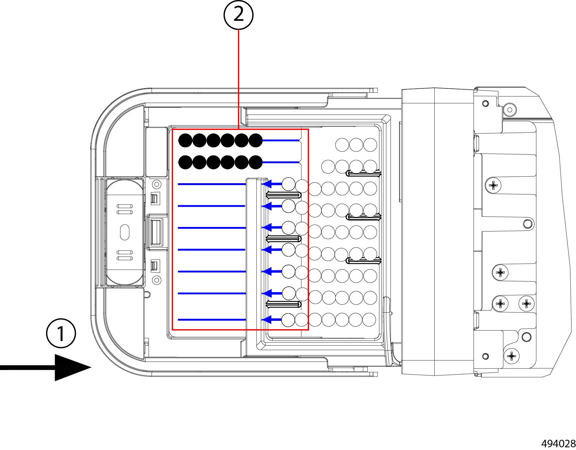
It is critical that the slots on the air filter assembly align correctly with the cable, as shown by blue arrows pointing to alignment with the slot on the air filter assembly. If the CMA and the slots on the air filter assembly are misaligned, the cables can get pinched and potentially become damaged or disconnected from the chassis.
Bezel Alignment with the Air Filter Assembly
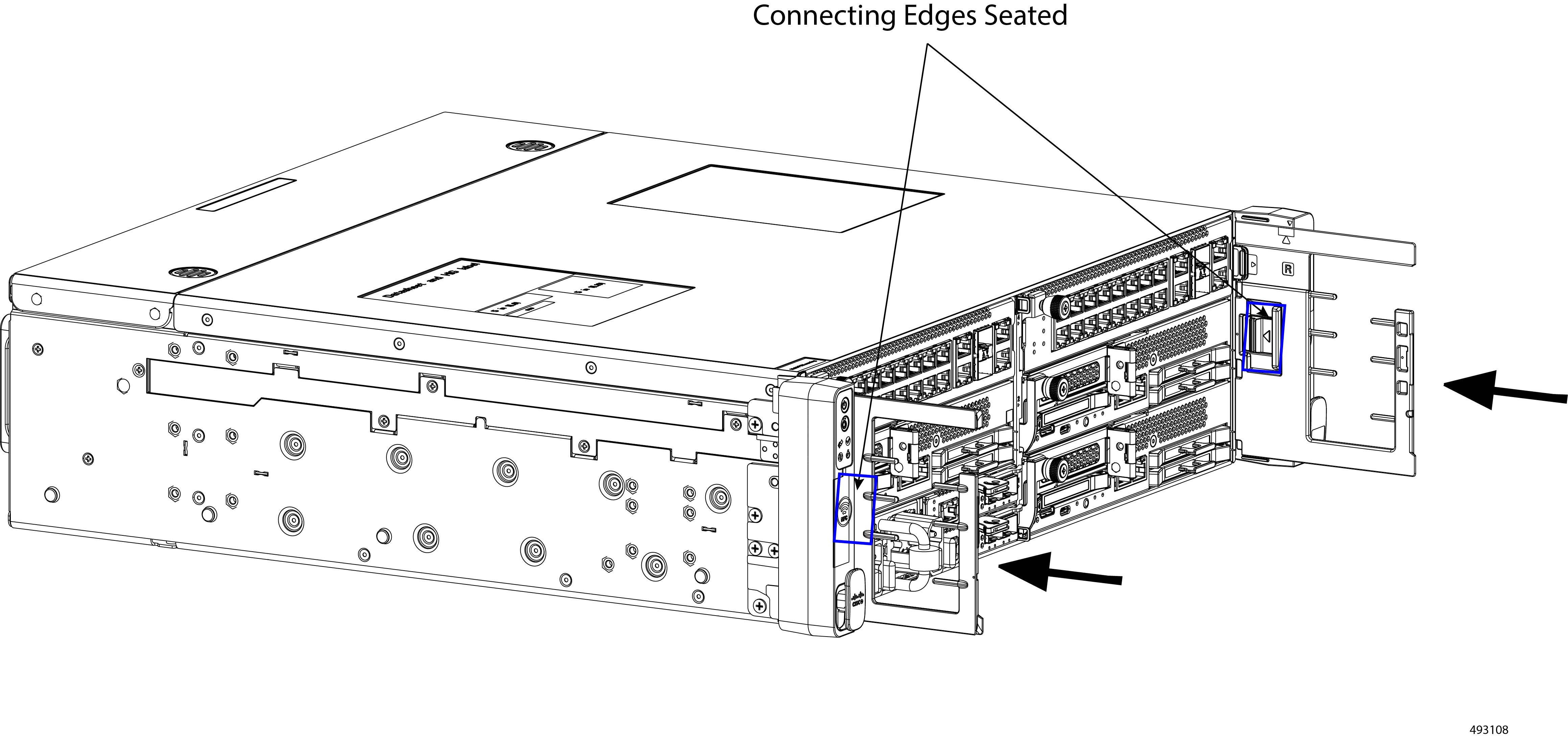
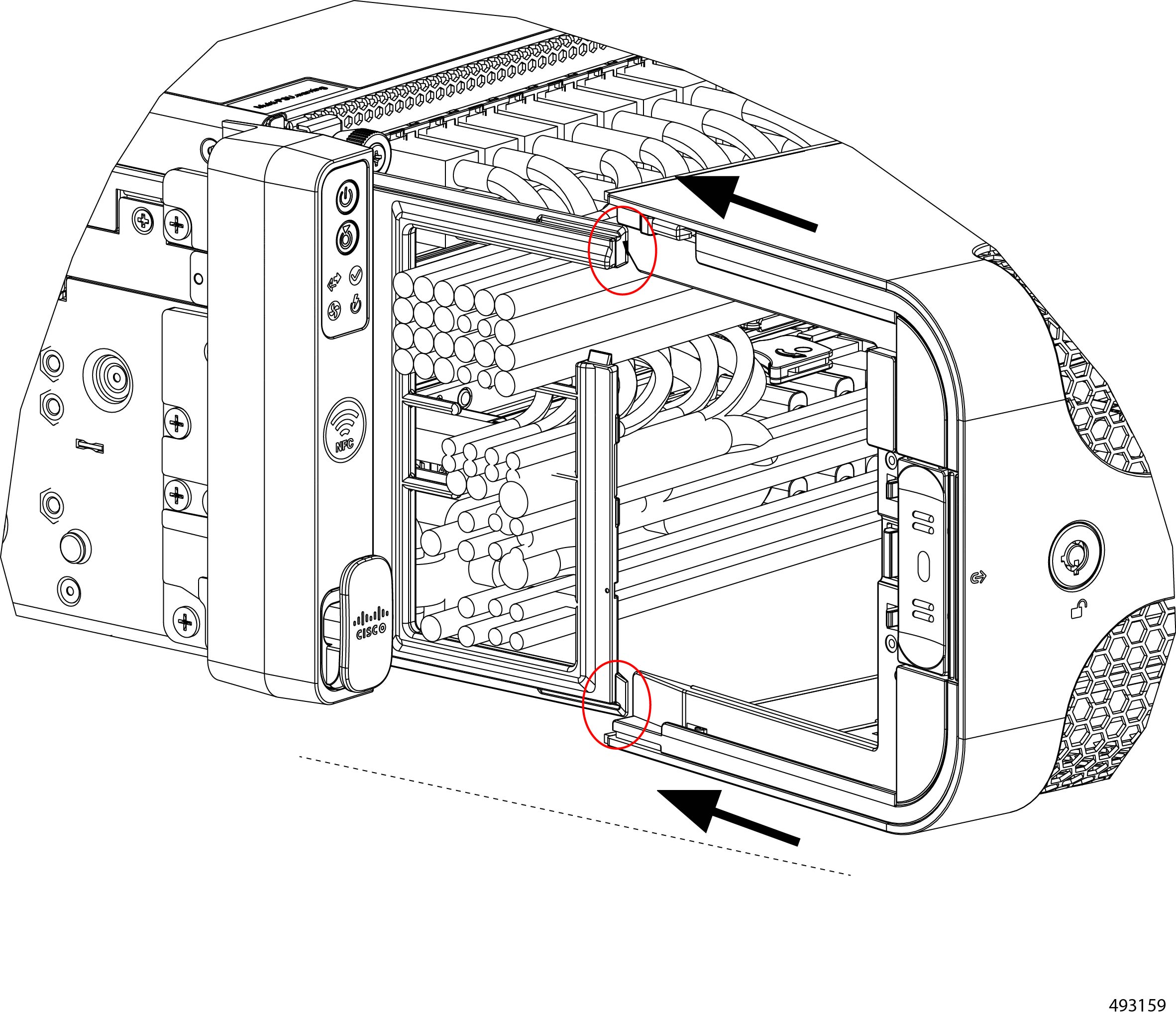
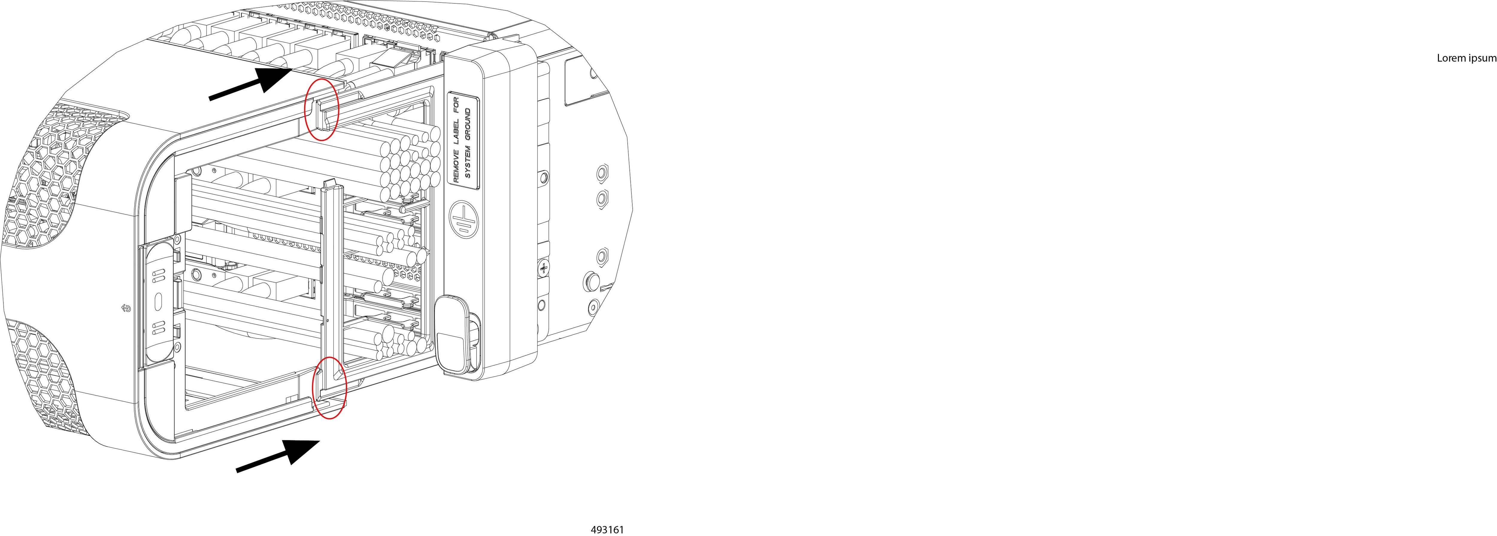
While installing the air filter assembly onto the CMAs, it is possible for the cables to cause the rails and grooves of the bezel and CMAs to become misaligned. When you have installed the bezel and the air filter assembly within it, visually inspect the following:
-
top and bottom edges
-
The edges around the bezel's release button.
If any of these edges are not correctly seated, the bezel/air filter assembly is misaligned with the CMAs. You must gently detach the bezel/air filter and attempt reinstalling it.
Removing the Air Filter Assembly
The air filter assembly consists of a foam filter and a filter frame. The foam filter requires regular replacement to ensure efficient filtration for the chassis. For more information, see Guidelines and Considerations for the Foam Filter. As part of replacing the foam filter, you must remove the entire air filter assembly.
To remove the air filter assembly (UCSXE-BEZ-FLTR) and replace the foam filter itself (UCSXE-FLTR-FOAM=), use this task.
Before you begin
The security bezel must be removed from the chassis to access the air filter assembly. If you have not removed the locking bezel already, do so now. See Removing the Security Bezel.
Procedure
|
Step 1 |
If you have not removed the bezel already, do so now.
|
||||
|
Step 2 |
When the bezel is removed from the chassis, disconnect the air filter assembly.
|
||||
|
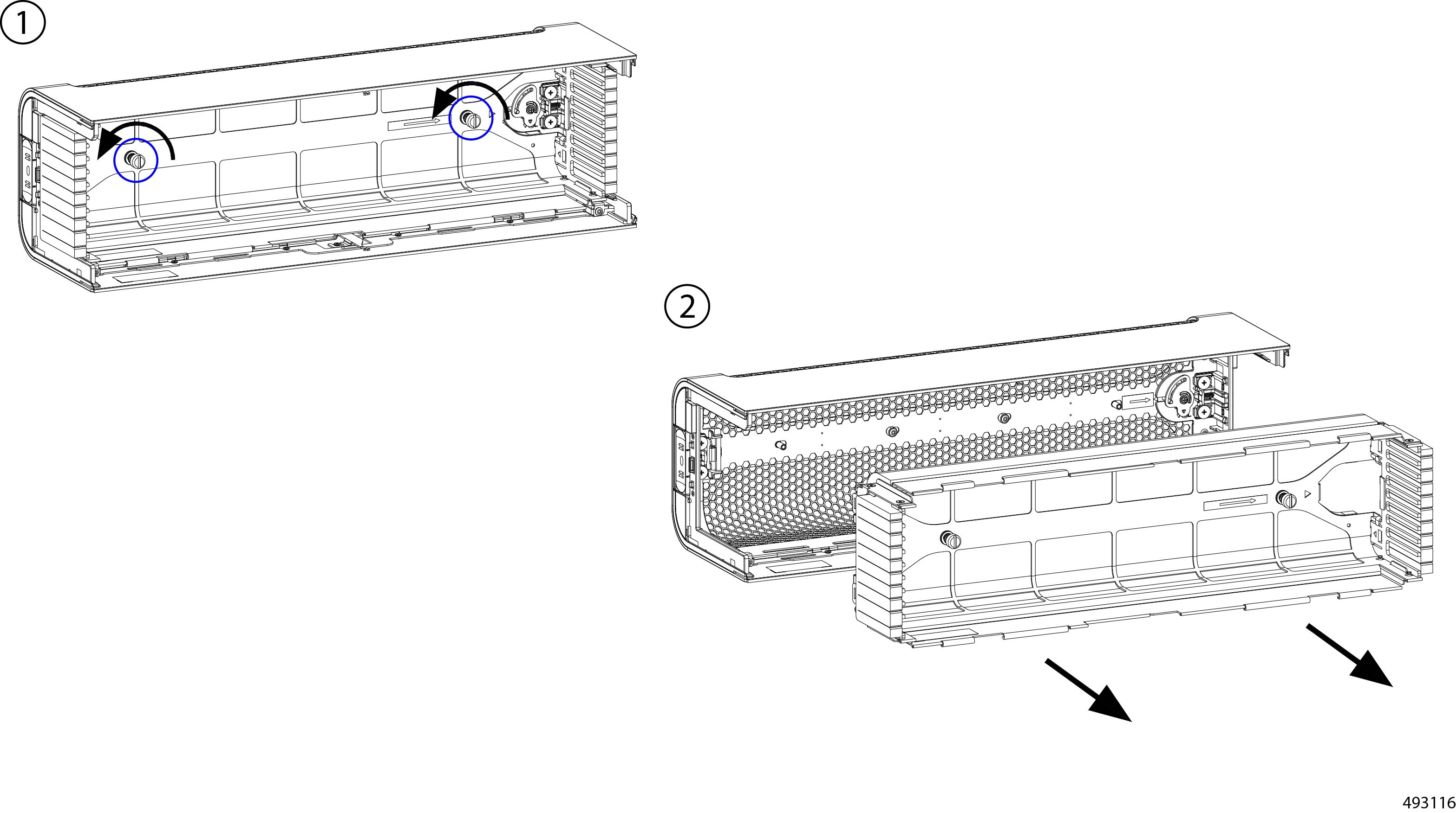
Step 3 |
(Optional) Replace the filter.
|
Installing the Air Filter Assembly
The air filter assembly installs into the security bezel by two captive thumbscrews.
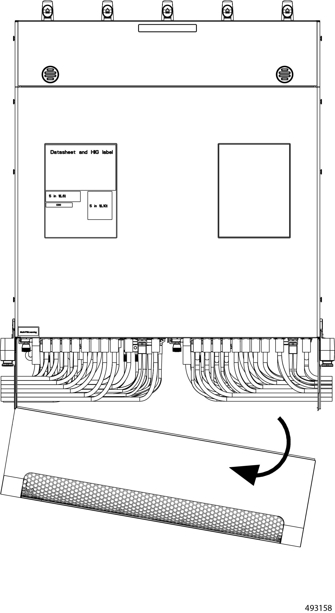
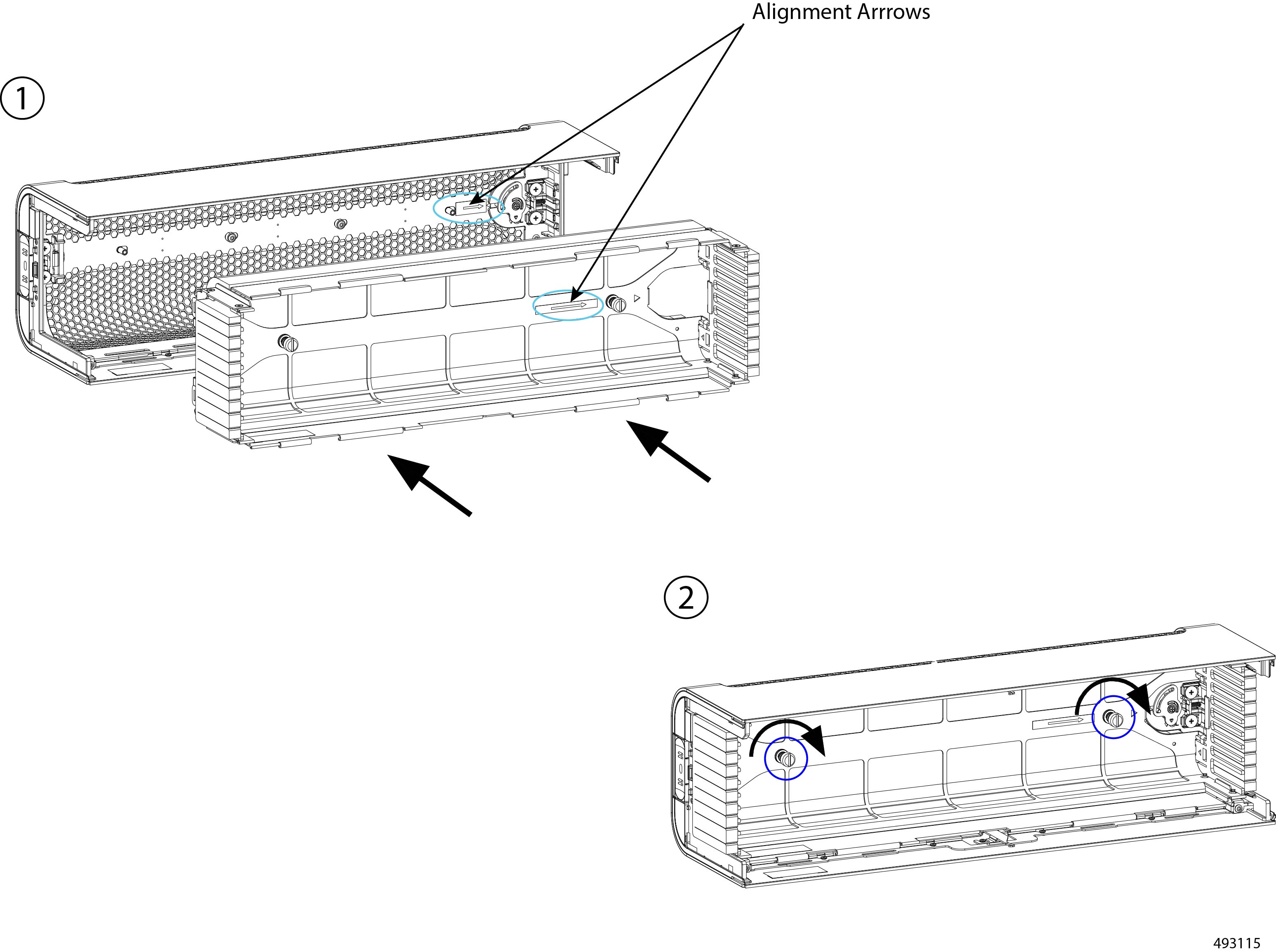
The bezel and the filter assembly have an arrow on this inside face of each, as shown in the illustration. These arrows are an alignment feature that show the direction that each piece should face to complete attaching them together properly.
Before you begin
Caution |
When installing the air filter assembly, the sides of the air filter assembly contain slots that must correctly align with the slots in the cable management assembly (CMAs). For more information, see Air Filter Assembly Alignment Considerations. |
Procedure
|
Step 1 |
Connect the filter assembly to the security bezel.
|
||||
|
Step 2 |
Install the bezel onto the chassis and, optionally, use the key to lock the bezel to the chassis. |
Replacing E3S Drives
The server's compute nodes can support E3.S EDSFF NVMe drives in varying amounts depending on the number of compute nodes and their configuration options.
The E3.S drives are hot swappable and front-loading. You can remove and install a drive without having to remove the top cover.
To replace an E3.S drive, use the following tasks.
Removing E3S Drives
Each E3.S drive is installed in the front of a compute node. Drives are easily accessible and removing them is a toolless task.
Removing an E3.S drive is accomplished by releasing the ejector and sliding the drive out of its drive bay on the compute node. You do not need to remove the top cover to perform this task.
Procedure
|
Step 1 |
Press the ejector button to unlock the ejector. |
||
|
Step 2 |
Holding the ejector level, swing it to the open position. 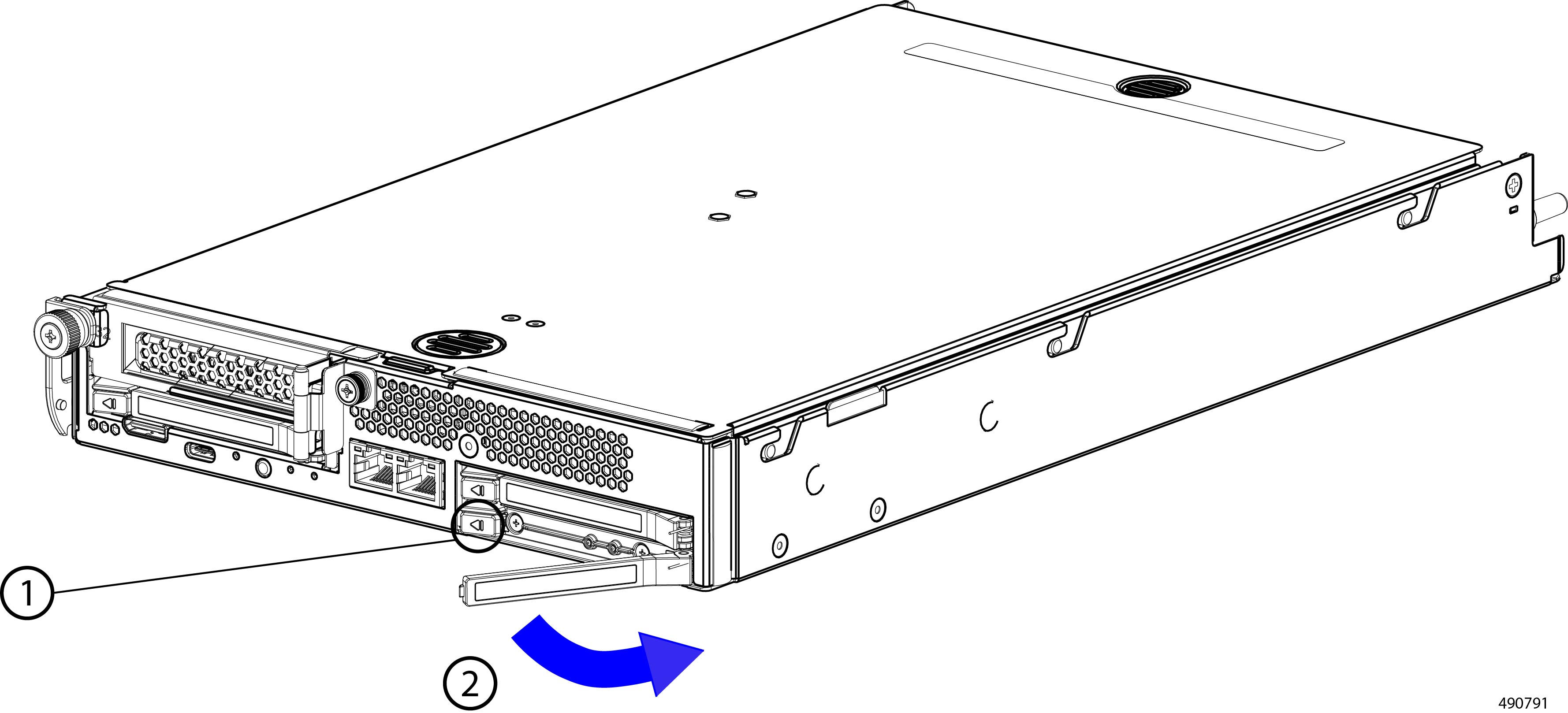 |
||
|
Step 3 |
Grasp the ejector, and keeping the drive level, slide the drive out of the drive bay.
|
Installing E3S Drives
Each E3.S drive is installed in the front of a compute node.
Installing an E3.S drive is accessible from the front of the chassis and is a toolless task. You do not need to remove the top cover to perform this task.
Drives are keyed so that they cannot be installed incorrectly.
Procedure
|
Step 1 |
Orient the drive so that the ejector button is on the left side. |
||
|
Step 2 |
Holding the drive level, gently swing the ejector to the open position.
|
||
|
Step 3 |
Holding the drive level, carefully slide it into the drive bay. While sliding the drive in, you might find it helpful to support the underside of the drive with your other hand. 
|
||
|
Step 4 |
Holding the ejector level, swing it horizontally to the closed position. When fully closed, the ejector should click into place as the drive locks into place. |
Replacing DIMMs
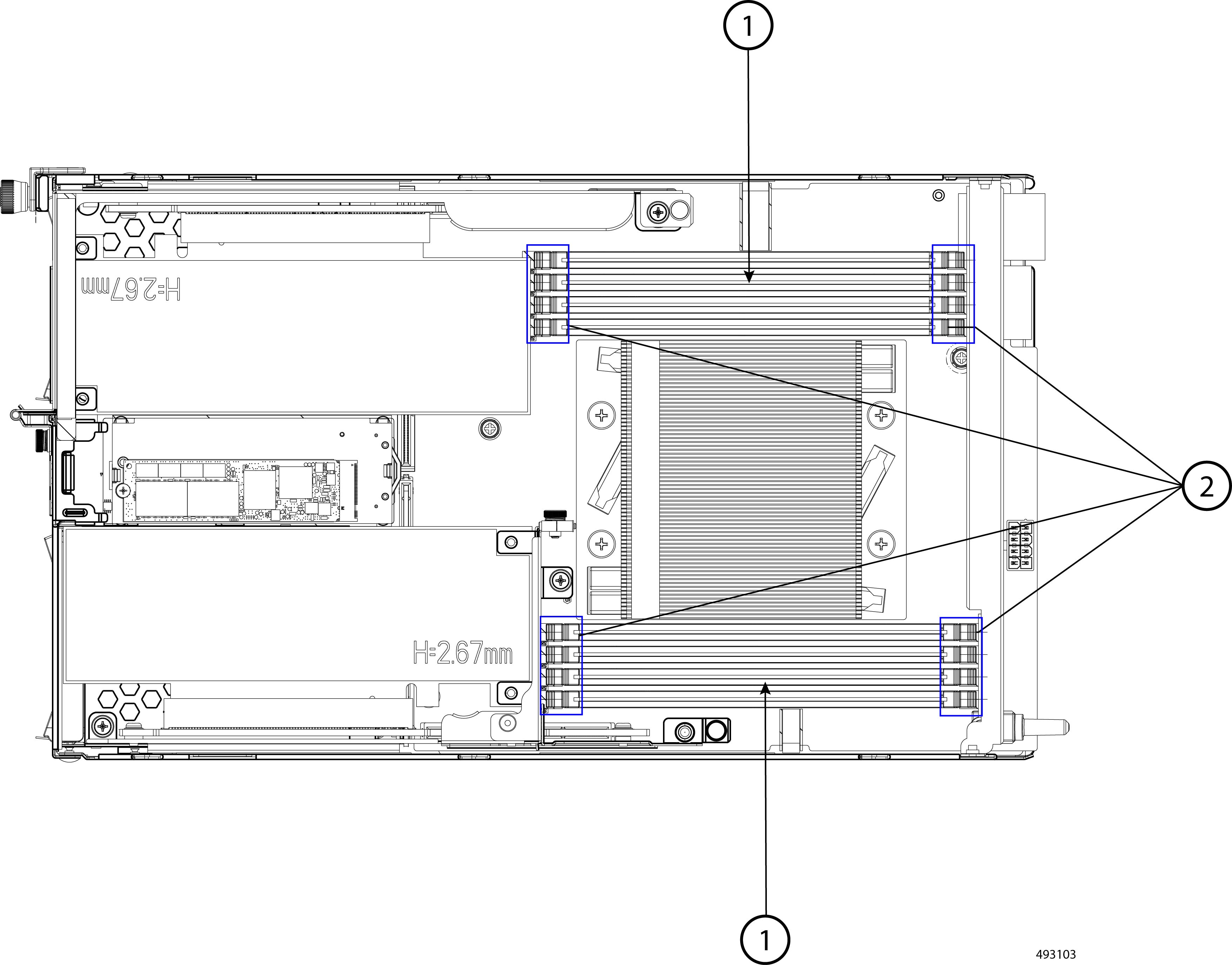
Each compute node features eight DIMM sockets that can support DDR5 DIMMs. A given memory channel has 1 or 2 DIMMs installed. DIMM sockets are color coded also for easier loading. DIMM socket 1 is blue, while DIMM socket 2 is black.
The following illustration shows the DIMM slot identifiers.
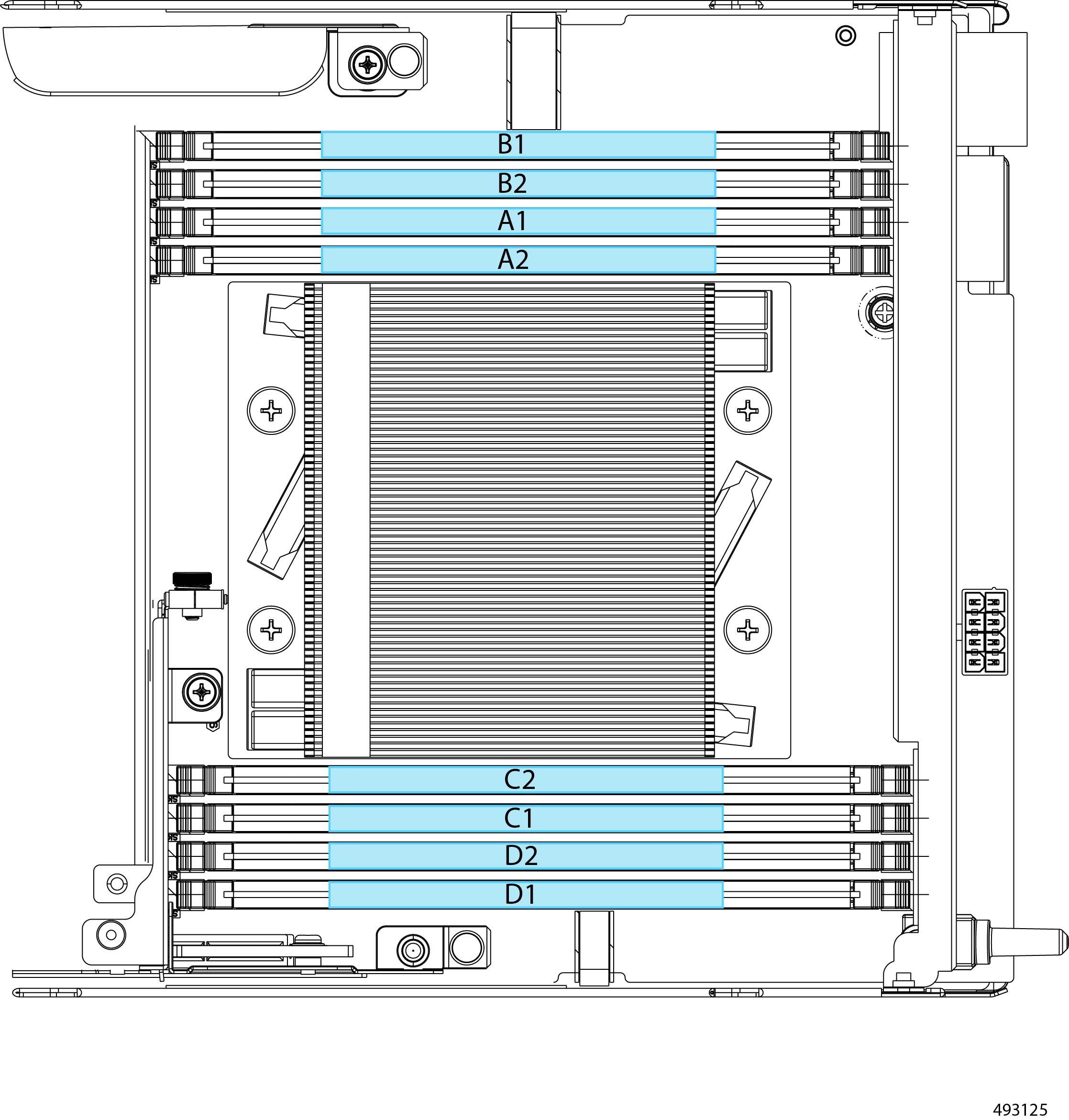
The following table shows the memory population rules.
|
Total Number of DIMMS |
Blue Socket |
Black Socket |
|---|---|---|
|
2 |
A1, C1 |
|
|
4 |
A1, B1, C1, D1 |
|
|
8 |
A1, B1, C1, D1 |
A2, B2, C2, D2 |
For additional details, consult the Cisco UCS XE130c M8 Compute Node Memory Guide.
To replace DIMMs on the compute nodes, follow this procedure:
Removing DIMMs
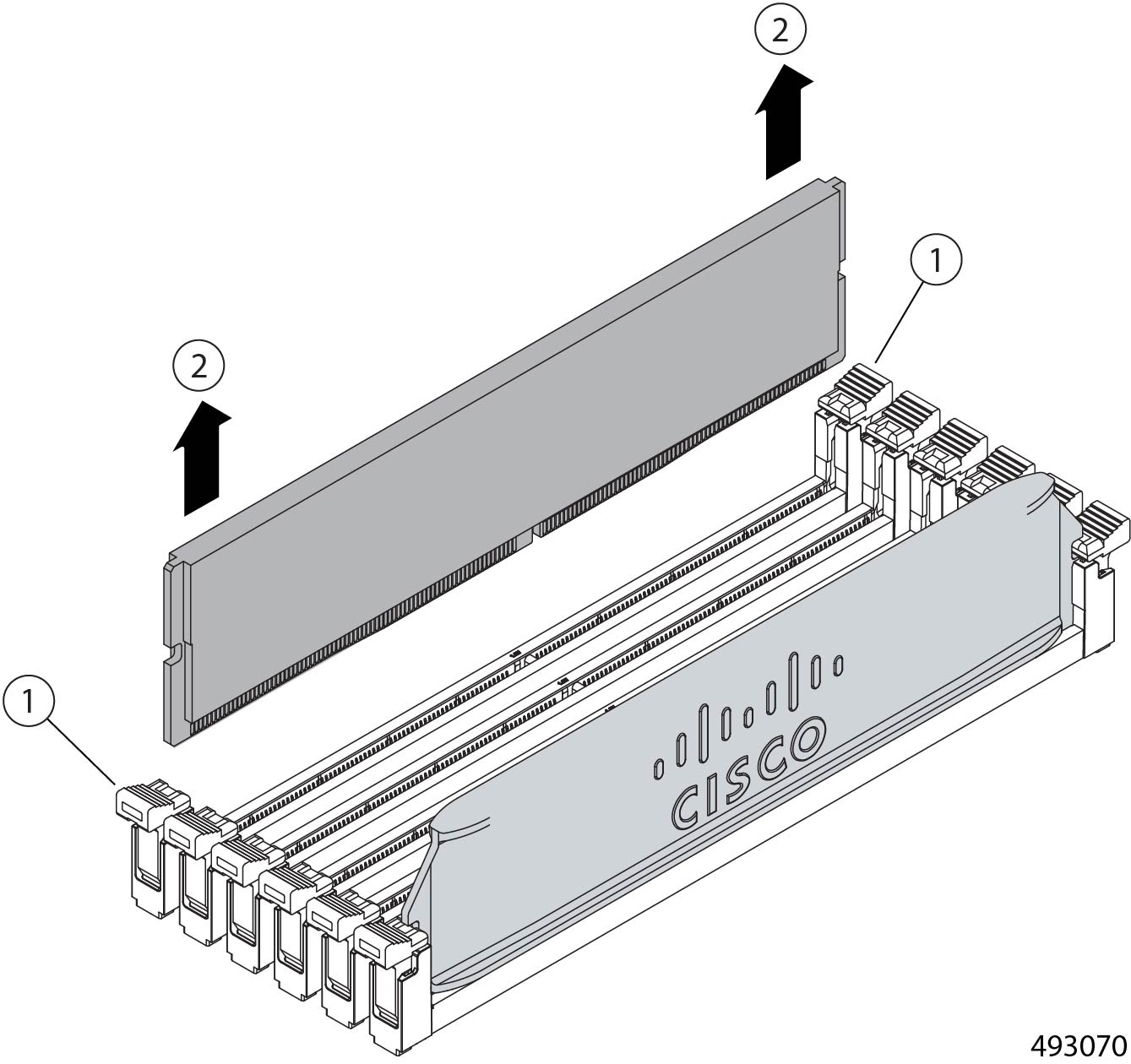
Each Cisco UCS X130c Compute Node has eight memory sockets connected to the CPU that support DDR5 DIMMs. DIMMs are installed in the sockets and held in place by connector latches. You can remove DIMMs by opening the connector latches. Removing DIMMs from the compute node is a tool-less procedure.
Use the following procedure to remove DIMMs from the compute node.
Procedure
|
Step 1 |
Remove the compute node. Go to Removing a Compute Node. |
||||
|
Step 2 |
Remove the node's top cover. |
||||
|
Step 3 |
Remove the DIMM modules from the node.
|
Installing DIMMs
The UCS X130c compute node is shipped with DIMMs pre-installed. However, if you need to install DIMMs, you can do so by installing a DIMM into its socket until it clicks into place. Installing DIMMs is a tool-less process.
Use the following procedure to install a DIMM module into an empty socket on the compute node.
Procedure
|
Step 1 |
Push the connector latch at each end of the socket outward. This is the open position. |
|
Step 2 |
Align the DIMM module with the socket, making sure that the DIMM's connector (golden fingers) are pointing down. |
|
Step 3 |
Insert the DIMM into the socket and gently press down until the module clicks into place. |
|
Step 4 |
When you have completely inserted DIMMs as needed, reinsert the compute node. Go to Installing a Compute Node. |
Replacing the Compute Nodes
The chassis features three versions of compute node, each based on the number of CPU cores.
-
Twelve core version (UCSXE-130C-M8-12)
-
Twenty core version (UCSXE-130C-M8-20)
-
Thirty-two core version (UCSXE-130C-M8-32)
Each version of compute node is hot-swappable and field-replaceable. When you replace the compute node, you will disconnect it from the power backplane, so the node will power down. When you reinsert the compute node, the node automatically powers on after reconnecting to the power backplane.
When replacing a compute node, you can choose to reinsert it into the same slot, or you can insert it into another slot.
You cannot install a compute node into a Chassis Management Controller slot. Also, you cannot install a Chassis Management Controller module into a compute node slot.
To replace any version of compute node, use the following tasks.
Removing a Compute Node
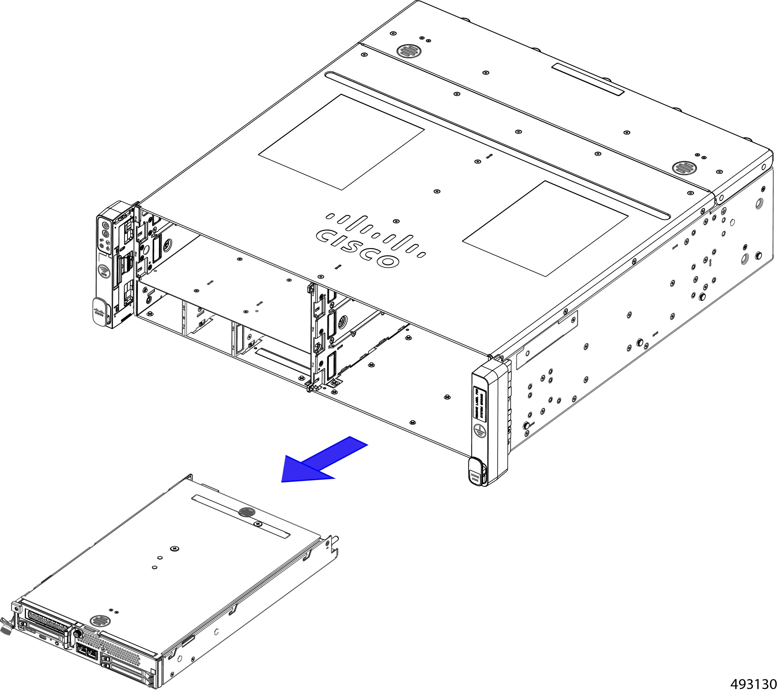
Each compute node is installed in the front of the chassis.
Removing a compute node is accomplished by releasing the ejector and sliding the node out of its slot in the chassis. You do not need to remove the top cover to perform this task.
To keep the chassis operating correctly, do not remove all compute nodes at one time.
Before you begin
Before attempting this task, gather a #2 Phillips screwdriver.
Procedure
|
Step 1 |
Using the screwdriver, loosen the compute node's captive screw. |
||
|
Step 2 |
Gently swing the ejector in a 45° downward arc until the ejector stops. This is the open position.  |
||
|
Step 3 |
Grasp the ejector and slide the compute node out of the chassis.
|
||
|
Step 4 |
If you will not be reinstalling a compute node, attach a node blank to the unused slot.
|
Installing a Compute Node
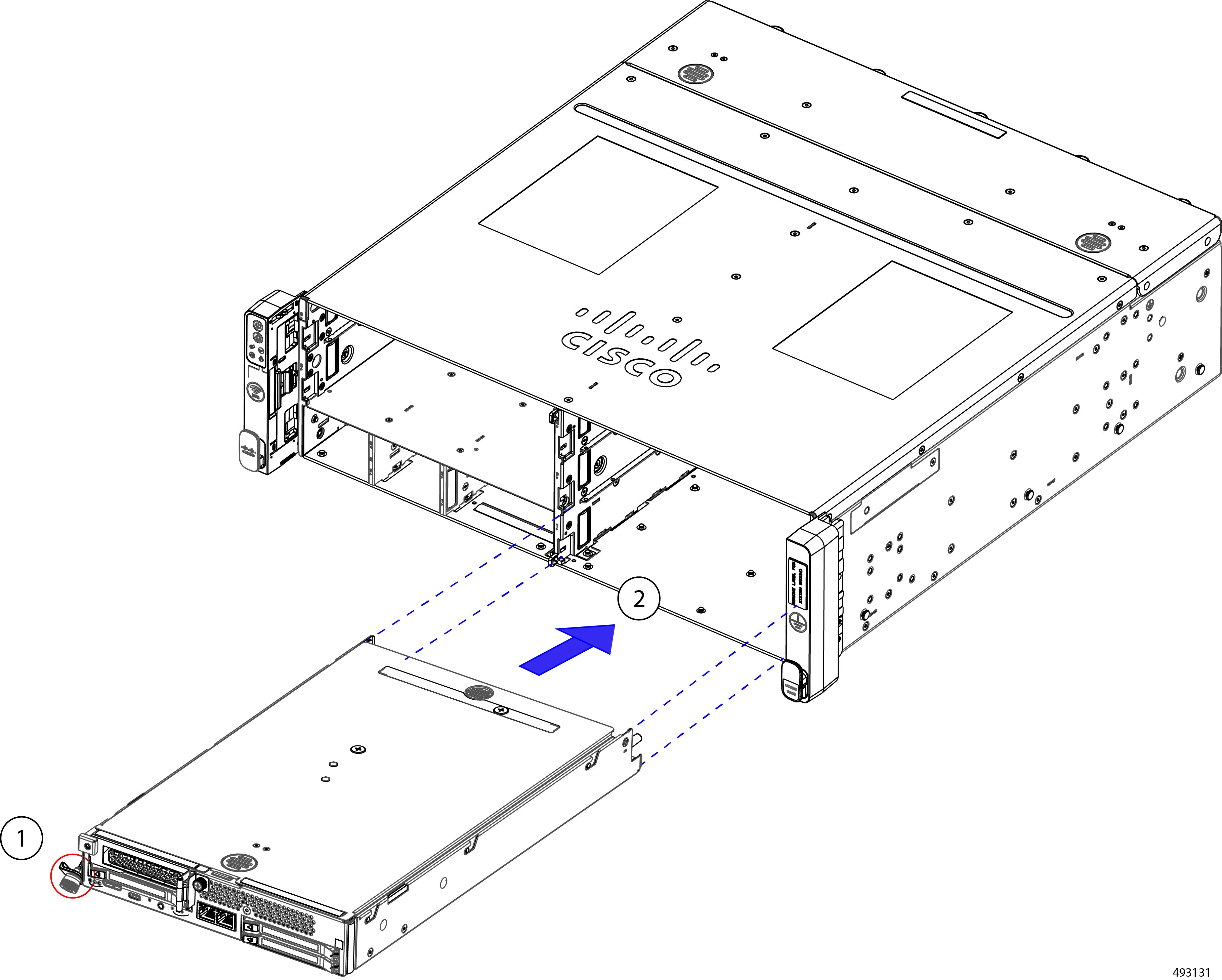
Each compute node is installed in the front of the chassis. Compute nodes are keyed so that they cannot be installed incorrectly.
Installing a compute node is accomplished by sliding the node into its slot in the chassis. You do not need to remove the top cover to perform this task.
Before you begin
Before attempting this procedure, gather a #2 Phillips screwriver, and a Torque driver or another way to measure the torque on the compute node's captive thumbscrew.
Procedure
|
Step 1 |
Verify that the compute node's ejector is in the open position. The ejector is in the open position when it is at a 45° angle, not flush with the faceplate. |
||
|
Step 2 |
Align the compute node with the slot in the chassis. When correctly aligned, the top cover is facing up. |
||
|
Step 3 |
Support the underside of the compute node with your other hand, insert the compute node into the slot.
|
||
|
Step 4 |
When the compute node is almost fully installed, gently swing the ejector to the closed position. |
||
|
Step 5 |
Start threading the captive screw into the screwhole by hand. |
||
|
Step 6 |
Using a torquedriver, tighten the compute node's captive thumbscrews to the range of 4.2 in-lbs to 5.9 in-lbs (5.1 kg-cm to 6.9 kg-cm) of force.
|
Replacing the Compute Node RAID Controller
Each compute node contains an optional M.2 SATA RAID controller for compute node OS and boot information (UCSXE-M2-HWRD2).
The module supports a variety of SSD capacities, 240G 480G, or 960G. The following SSD options are available for the compute node, depending on whether standard or boot-optimized SSDs are desired.
-
M.2 SATA SSD, 240G capacity (UCSXE-M2-240G)
-
M.2 SATA SSD, 480G capacity (UCSXE-M2-480G)
-
M.2 SATA SSD, 960G capacity (UCSXE-M2-960G)
-
Boot-Optimized M.2 SSD, 240G (UCSXE-M2240OA1V)
-
Boot-Optimized M.2 SSD, 240G (UCSXE-M2480OA1V)
A single SSD connects to the module, and the module connects to the eCMC PCB through a USB 2.0 interface. This M.2 module is used as the boot drive for the compute node. RAID 0/1 as well as JBOD mode. Out-of-band management (OOB) is also supported.
The compute nodes E3.S drives can be used as boot devices if no M.2 SSDs are installed. However, M.2 SSDs are the preferred device. When replacing the compute node's M.2 RAID controller, be aware of the following:
-
M.2 drives support UEFI boot mode only; legacy boot mode is not supported.
-
If M.2 drives are selected, a minimum of 2 drives are required. Drives must be selected in quantities of 0 or 2 (QTY 1 is not allowed). Mixing of different M.2 SATA SSD capacities is not allowed within a single compute node.
-
Hot-plug replacement of the RAID controller is not supported. The compute node must be powered off to replace
Removing the Compute Node RAID Controller
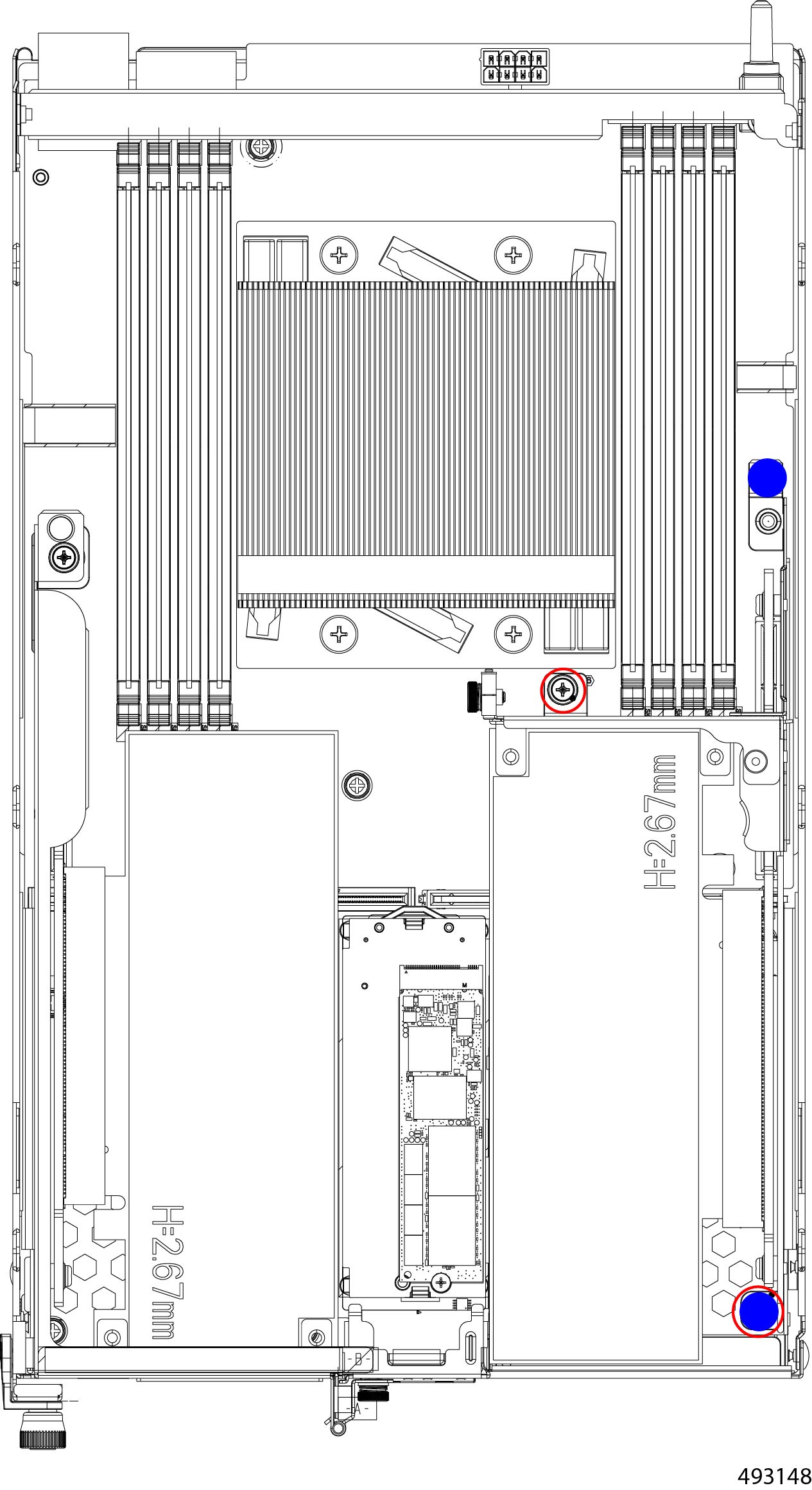
The compute node's M.2 RAID controller is installed between the compute node's PCI cages. The controller consists of a module (carrier) and a single M.2 SSD installed onto the module. The module is secured to the compute node by two release clips (one at each end of the controller) that apply pressure to each end of the module, plus two guide pins that catch the module and help hold it in place.
You can remove the M.2 RAID controller from the compute node as well as remove the single M.2 SATA SSD, when present.
Use the following procedure to remove the controller and SSD from the compute node.
Before you begin
Removing the controller is a toolless task, but removing the M.2 SSD requires a #2 Phillips screwdriver.
Note |
Hot-plug replacement of the RAID controller is not supported. The compute node must be powered off to replace the module and SSDs. |
Procedure
|
Step 1 |
Remove the compute node from the chassis. |
|
Step 2 |
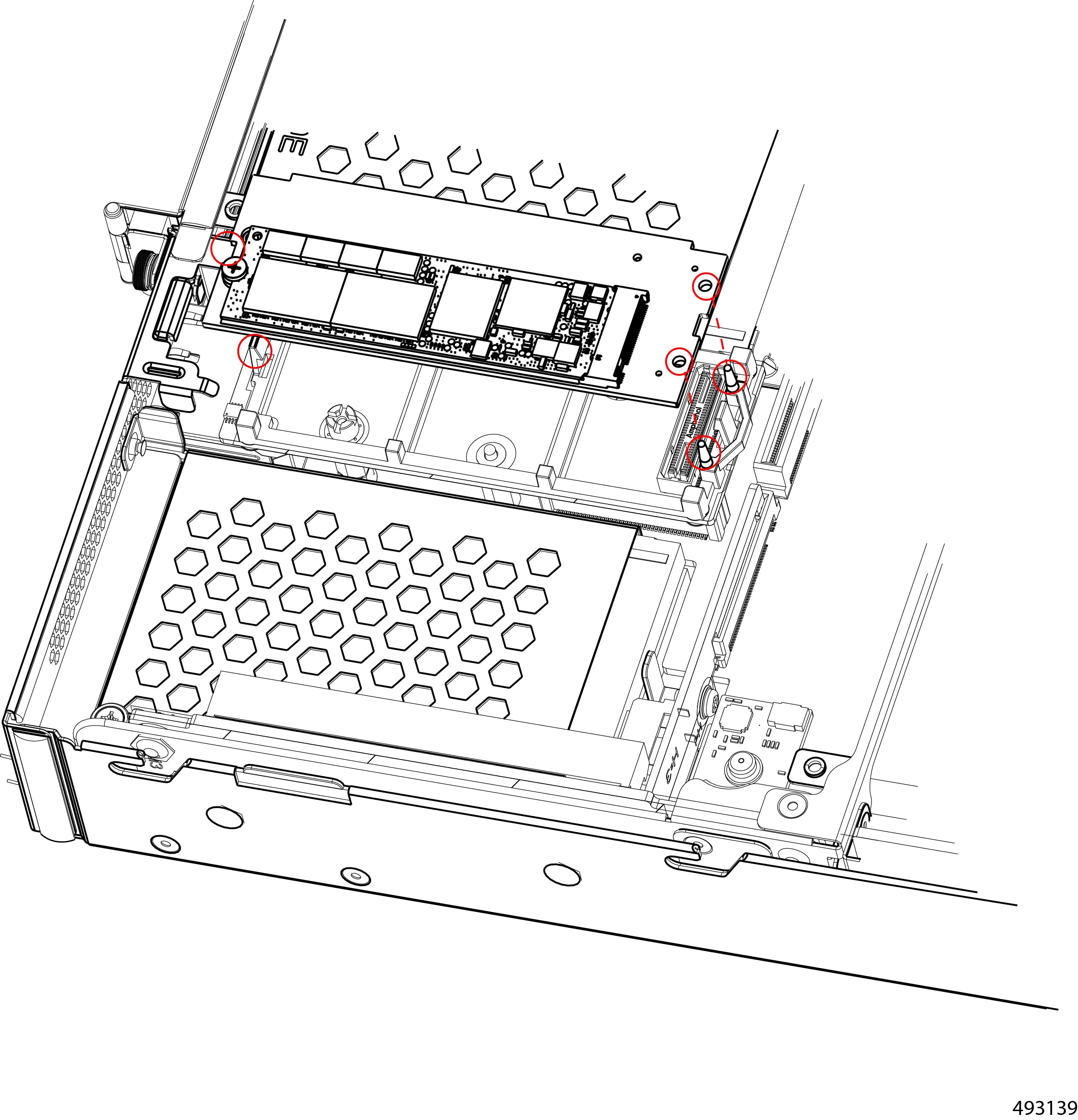
Locate the securing clips for the RAID controller.
|
|
Step 3 |
Remove the controller. |
|
Step 4 |
If needed, remove the SSD.
|
What to do next
Reinstall the SSD and controller.
See Installing the Compute Node RAID Controller.Installing the Compute Node RAID Controller
Each compute node contains an M.2 RAID controller used for booting the compute node. The M.2 RAID controller consist of one M.2 SSD that connects to the compute node by a key hole connector (socket) on the compute node.
To facilitate installation, the compute node has two guide pins on the compute node that insert into guide holes on the controller. These alignment features assist with correctly positioning the controller on the node and in the controller in place.
Use the following task to install the RAID controller and the SSD.
Before you begin
As part of this task, you can install a supported M.2 SSD while the RAID controller is removed from the compute node. Installing the RAID controller is a toolless process, but to install the SSD you will need a #2 Phillips screwdriver, torque driver or other tool to measure the torque on the SSD screw.
Procedure
|
Step 1 |
If needed, insert the SSD onto the controller.
|
|
Step 2 |
Install the controller onto the compute node.
|
|
Step 3 |
Reinstall the compute node. Go to Installing a Compute Node. |
Replacing a PCIe Card or Filler Panel on the Compute Node
The three-slot compute node can host an optional PCIe Gen5 HHHL PCIe adapter or card as a configuration option. For more information, see Supported PCIe Cards.
With this configuration, you can install or replace a corresponding PCIe card as a field-serviceable option. Installing or replacing a PCIe card requires you to remove the compute node from the chassis.
To replace a PCIe card on the compute node, use the following procedures.
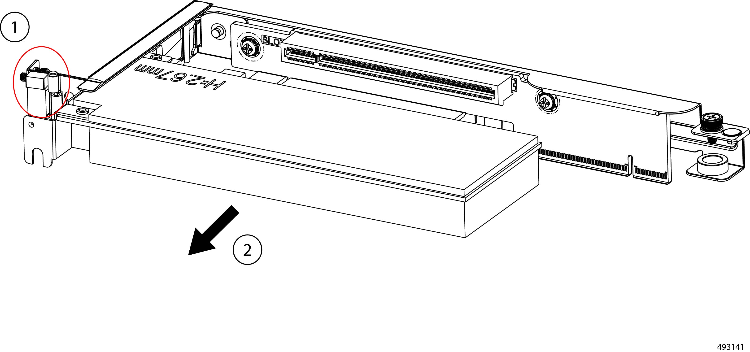
Removing a PCIe Card or Filler Panel from the Compute Node
In a three-drive configuration, slot 4 of the compute node has a PCIe riser cage that can accept a HHHL PCIe Gen5 x16 PCIe card. When you face the compute node, the PCIe cage is the left cage.
The card can be removed or replaced as part of hot-swapping the compute node. Use this task to remove the PCIe card, or a PCIe filler blank, from the PCIe cage.
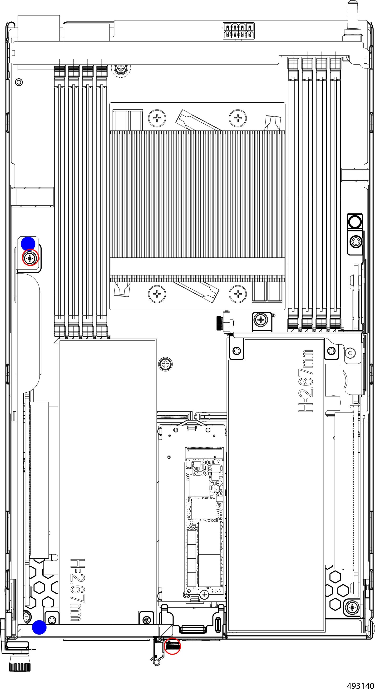
To facilitate removal, the PCIe cage has supported touch points where you should grasp the cage. For the illustrations in this topic, the touch points are indicated by a solid blue circle. Use the touch points when removing the PCI cage.
Before you begin
Gather a #2 Phillips screwdriver.
Procedure
|
Step 1 |
Remove the compute node from the chassis. Go to Removing a Compute Node. |
|
Step 2 |
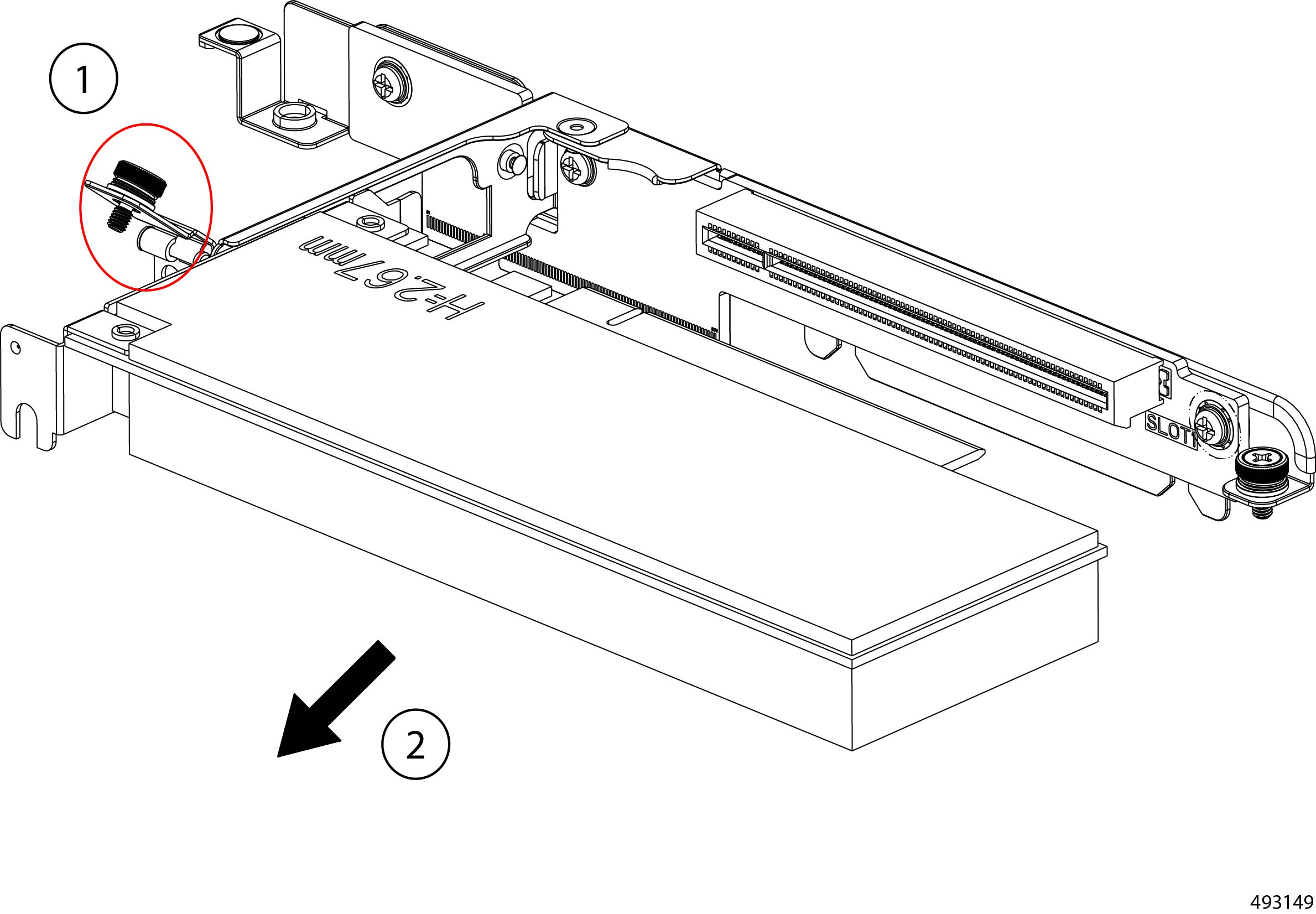
Remove the PCIe cage.
|
|
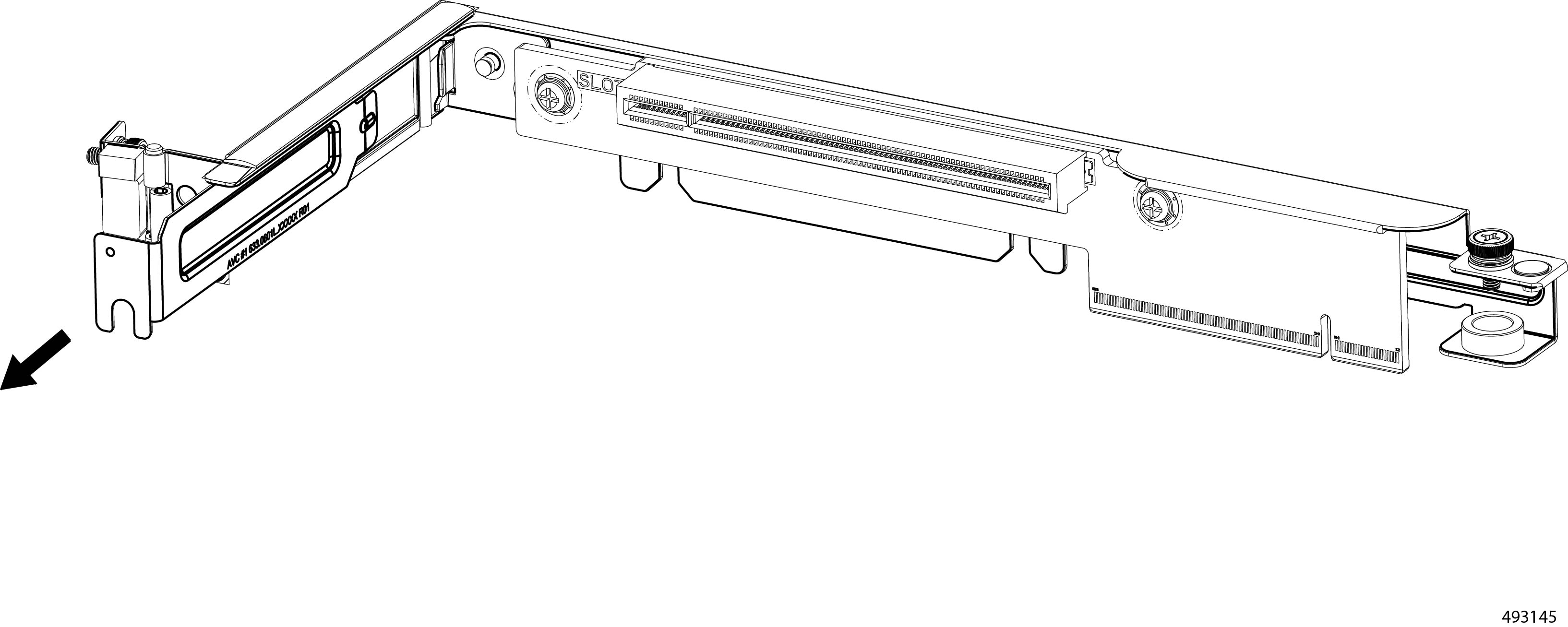
Step 3 |
Choose the appropriate option.
|
|
Step 4 |
Remove the PCIe card.
|
|
Step 5 |
Remove the PCIe filler blank.
|
What to do next
Insert PCIe card or filler blank.
Go to Installing a PCIe Card or Filler Panel on the Compute Node.
Installing a PCIe Card or Filler Panel on the Compute Node
Each three-drive compute node configuration can be customized by adding a PCIe card, which must support the following.
-
Physical form factor: Half height, half-length (HHHL)
-
PCIe support: PCIe Gen5 x16 lanes
-
Chassis presence: Installed only in the riser cage option for slot 4. As you face the compute node's front panel, this is the left PCIe cage.
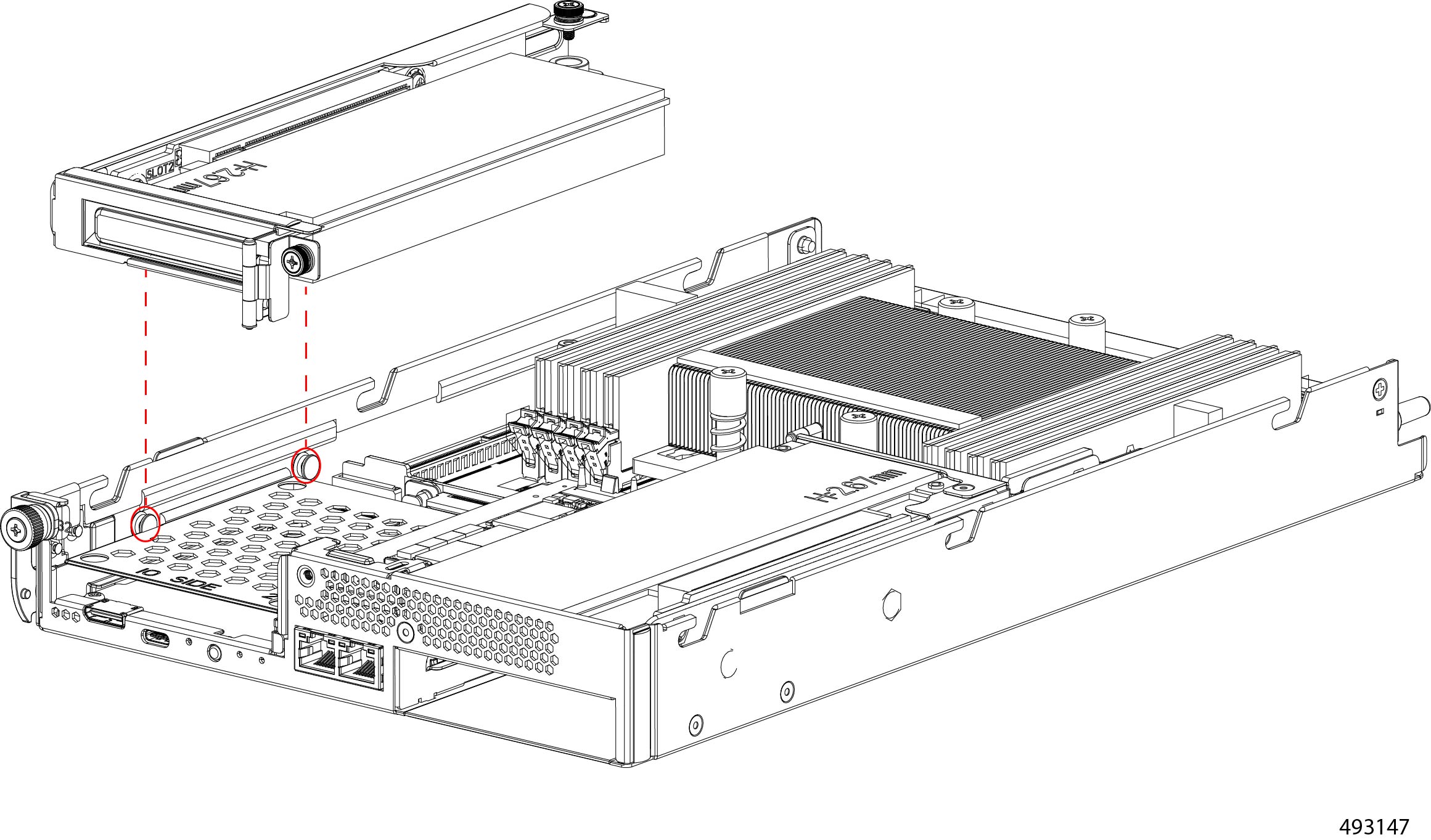
To facilitate installing the PCIe cage, it has the following features.
-
Supported touch points where you should grasp the cage. For the illustrations in this topic, the touch points are indicated by a solid blue circle. Use the touch points when installing the PCI cage.
-
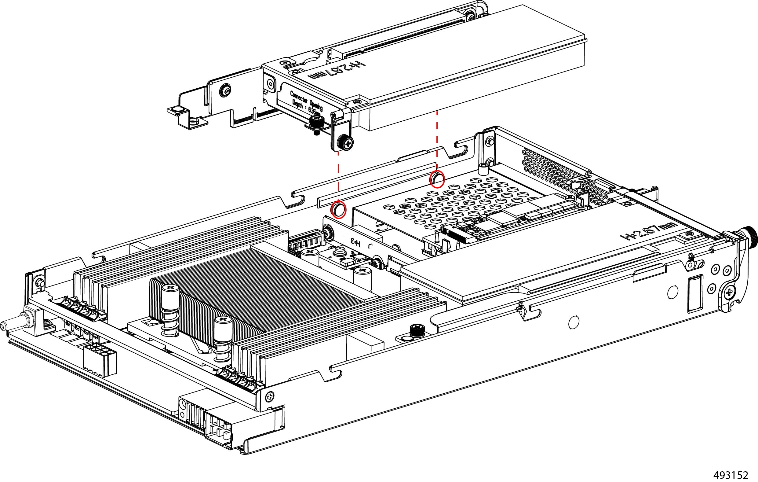
T pins on the inside of the compute node's sheetmetal wall and notches on the bottom of the PCIe cage. The T pins must insert into the notches to successfully seat the PCIe cage.
To install a PCIe card, you will insert the card into the PCIe socket inside the compute node's PCIe cage. The PCIe card can be installed as part of hot-swapping the compute node.
Before you begin
Before attempting this procedure, gather a #2 Phillips screwdriver and a Torque driver or another tool for measuring the torque applied to the PCIe cage screws.
Procedure
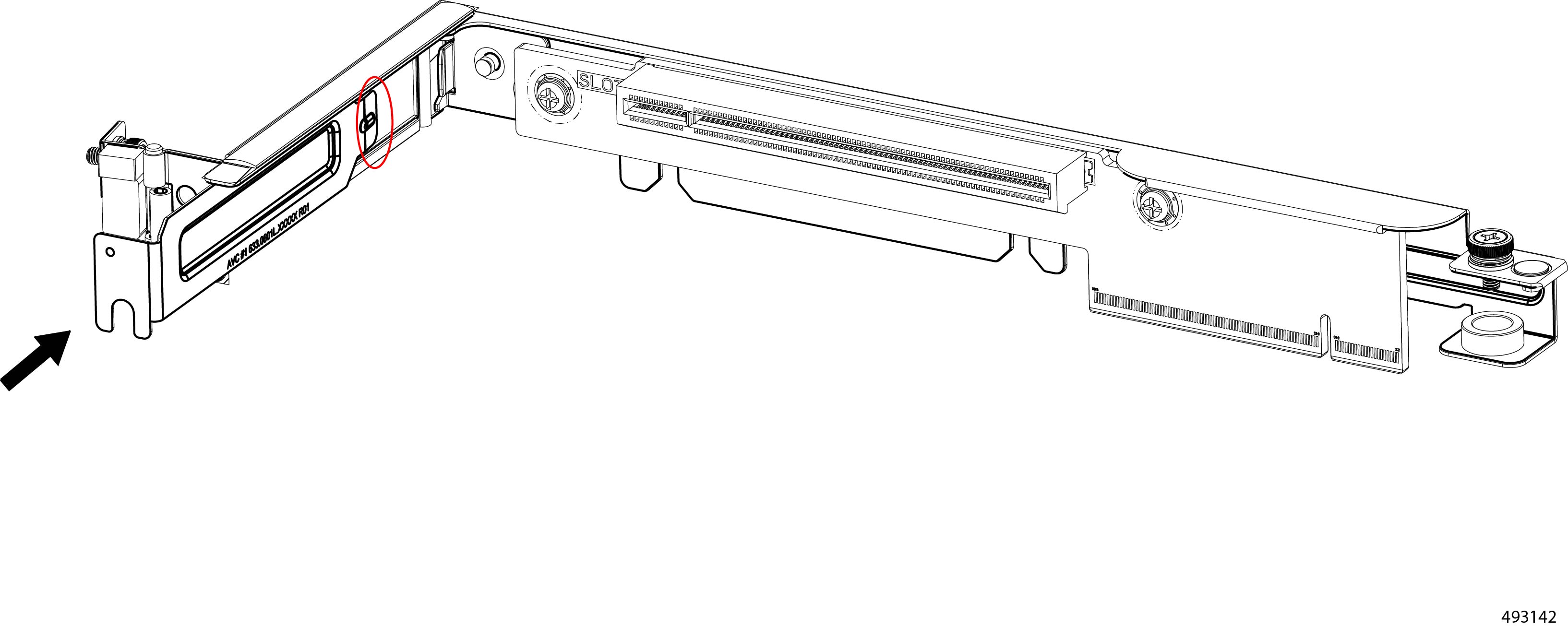
|
Step 1 |
Choose the following option, as needed.
|
|
Step 2 |
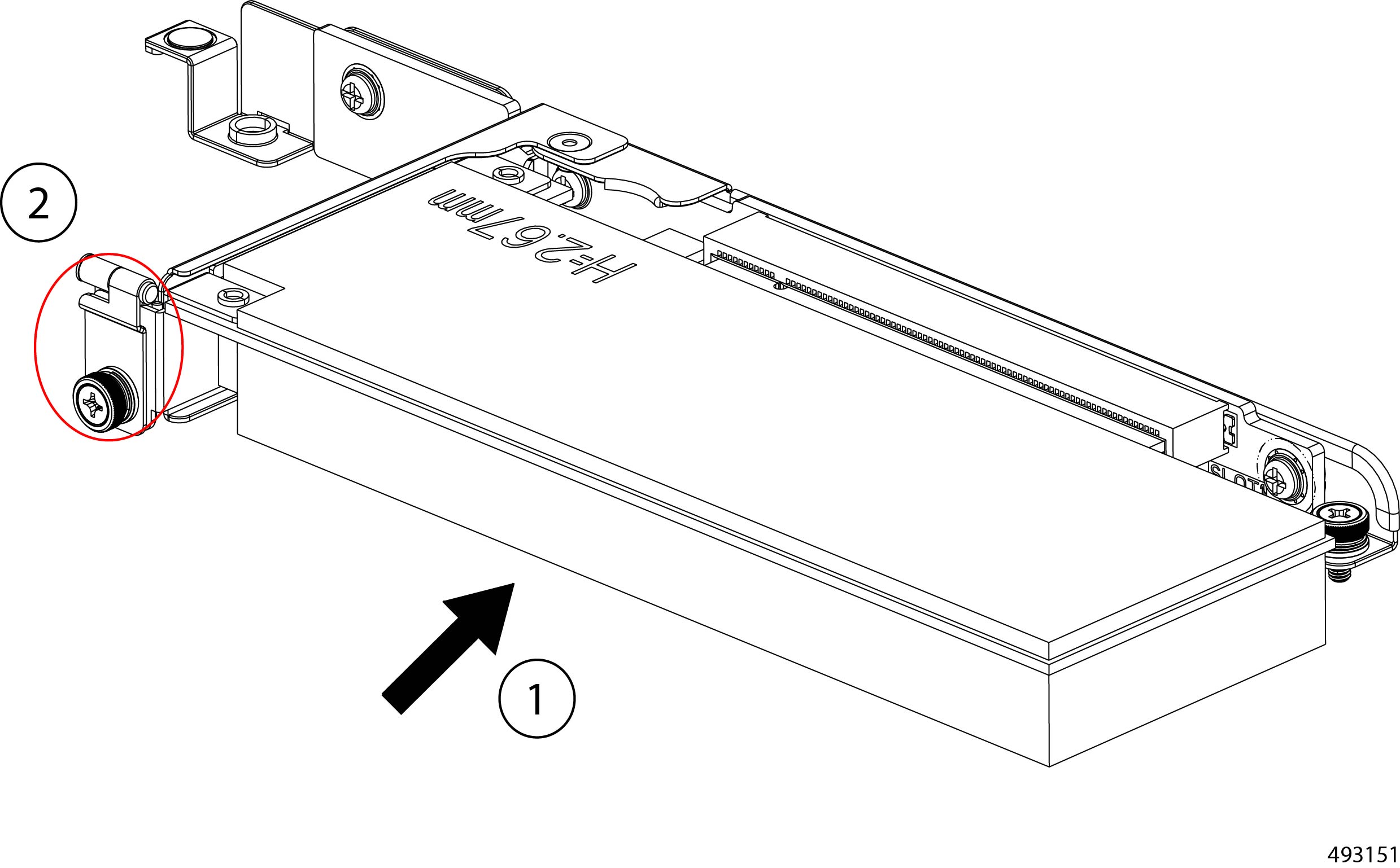
Install the PCIe card.
|
|
Step 3 |
Install the PCIe filler panel in the cage.
|
|
Step 4 |
Reinstall the PCIe cage.
|
|
Step 5 |
Reinstall the compute node. Go to Installing a Compute Node. |

Replacing a GPU on the Compute Node
Each Cisco UCS XE130c M8 Compute Node can support up to one optional half-height-half length GPU (UCSXE-GPU-L4).
The GPU can be installed in a riser cage above slots one and two. This riser cage is on the right side of the compute node. For more information, see Supported GPUs.
To replace a GPU on the compute node, use the following procedures.
Removing a GPU from the Compute Node
The compute node supports an optional HHHL GPU in the right PCIe cage. The GPU is field replaceable and can be removed or replaced while hot swapping the compute node. As part of removing the GPU, you must remove the PCIe cage.
To facilitate removal, the PCIe cage has supported touch points where you should grasp the cage. For the illustrations in this topic, the touch points are indicated by a solid blue circle. Use the touch points when removing the PCI cage.
Before you begin
Gather a #2 Phillips screwdriver.
Procedure
|
Step 1 |
Remove the compute node from the chassis. Go to Removing a Compute Node. |
||
|
Step 2 |
Remove the PCIe cage.
|
||
|
Step 3 |
Remove the GPU.
|
What to do next
Insert a GPU.
Installing a GPU on the Compute Node
Each compute node can support AI intent (COMPUTE-AI) through an optional HHHL GPU that can be installed in the right PCIe cage on the compute node. The GPU card can be installed as part of hot-swapping the compute node.
Note |
Do not operate the compute node with an empty PCIe slot. If you will not install a GPU, install a PCIe filler blank. |
Before you begin
Before attempting this procedure, gather a #2 Phillips screwdriver and a Torque driver or another tool to measure the torque when tightening the PCIe cage screws.
To facilitate installing the PCIe cage, it has the following features.
-
Supported touch points where you should grasp the cage. For the illustrations in this topic, the touch points are indicated by a solid blue circle. Use the touch points when installing the PCI cage.
-
T pins on the inside of the compute node's sheetmetal wall and notches on the bottom of the PCIe cage. The T pins must insert into the notches to successfully seat the PCIe cage.
Procedure
|
Step 1 |
Install the GPU into the PCIe cage.
|
|
Step 2 |
Reinstall the PCIe cage.
|
|
Step 3 |
Reinstall the compute node. Go to Installing a Compute Node. |
Replacing Node Blanks
The Cisco UCS XE9305 Chassis has five slots for compute nodes. Slots are numbered right to left, bottom up, so slot one is at the bottom right. Slot numbers are silkscreened onto the chassis for easy identification.
When shipped from the factory, slots can be populated with node blanks in slots one through five. Node blanks contain ventilation holes and are installed to protect the slots and ensure proper ventilation.
If your chassis does not have a compute node installed in a slot, that slot must have a node blank installed. Do not operate the chassis without a compute node or node blank installed.
To replace node blanks, use the following topics.
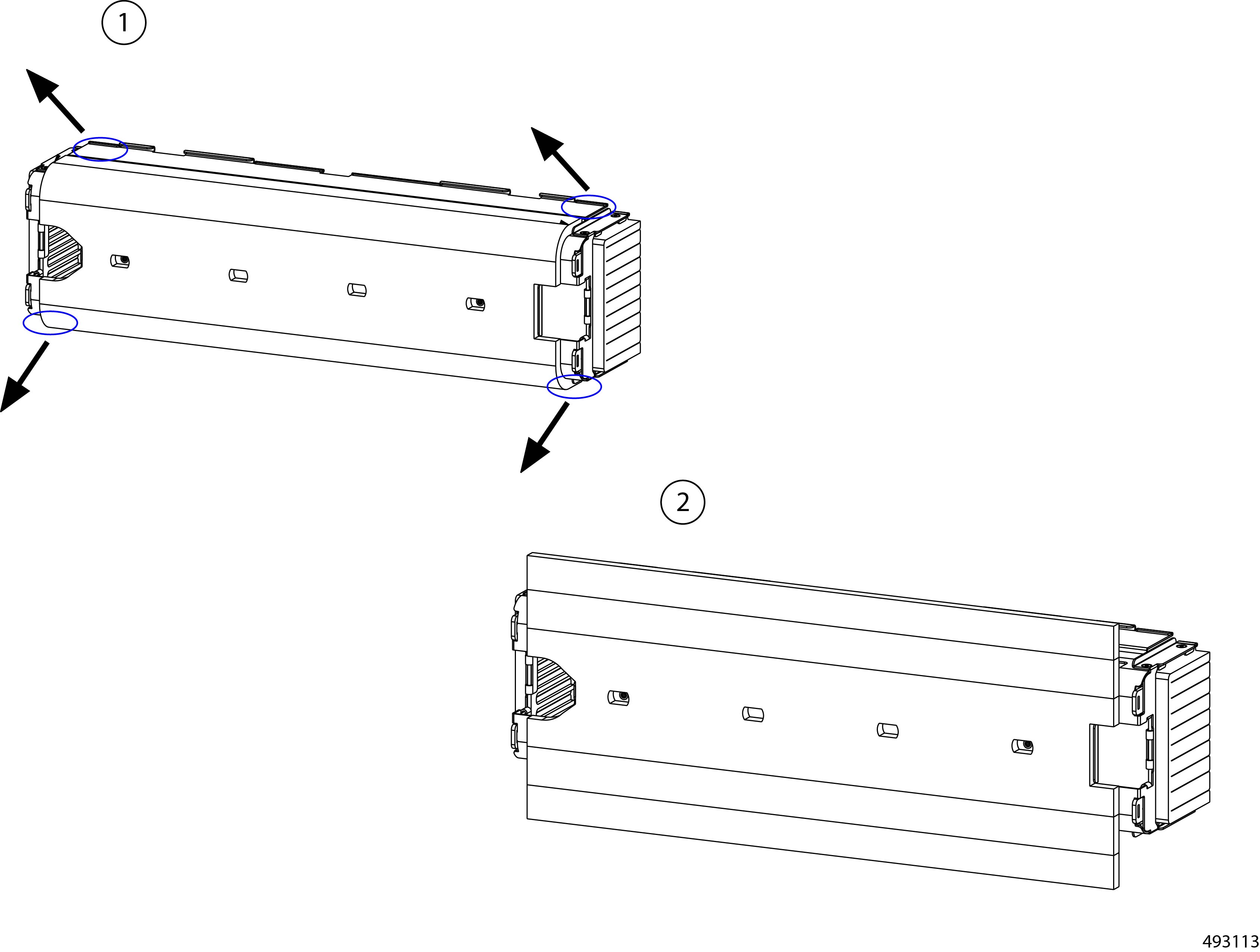
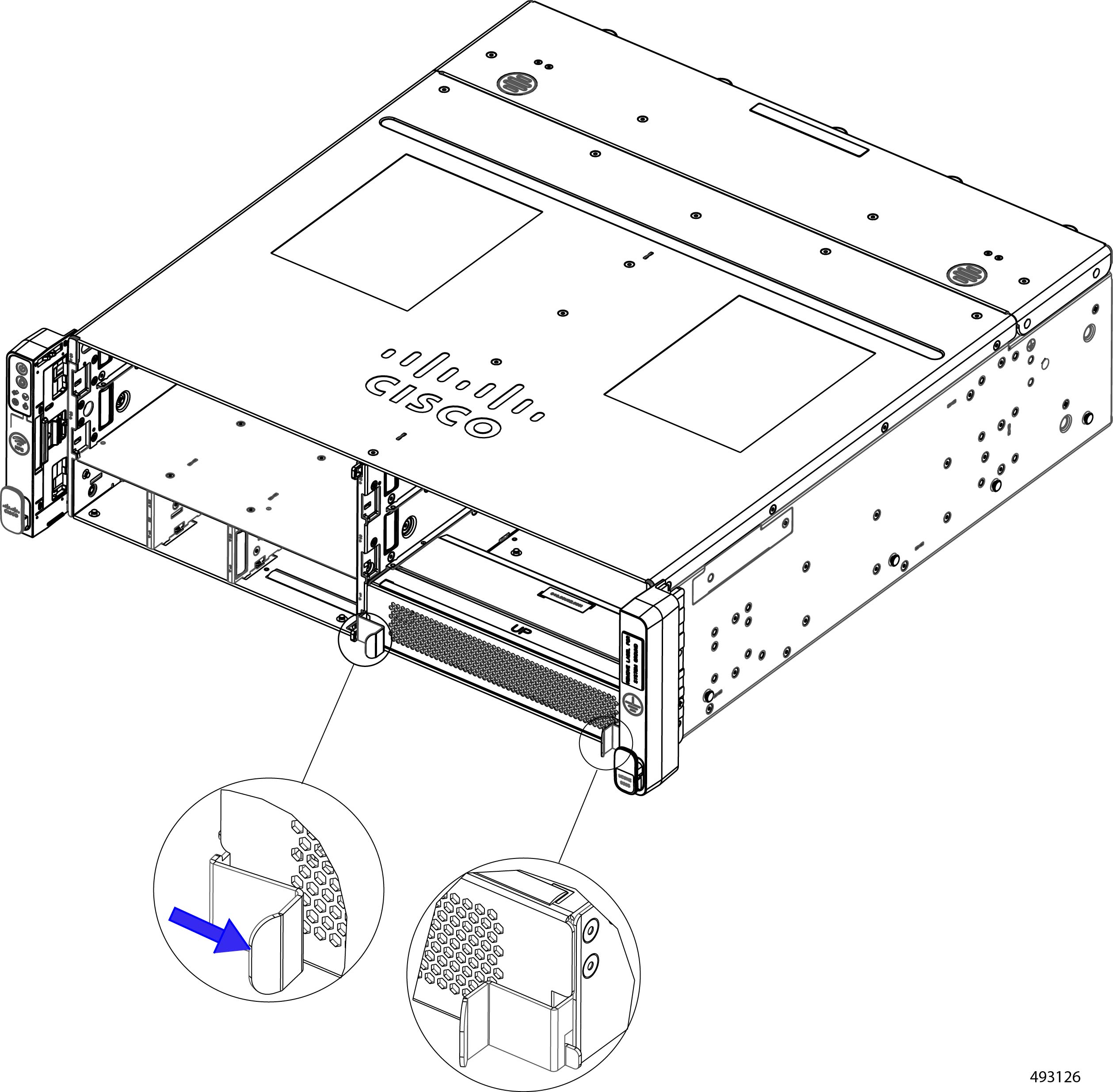
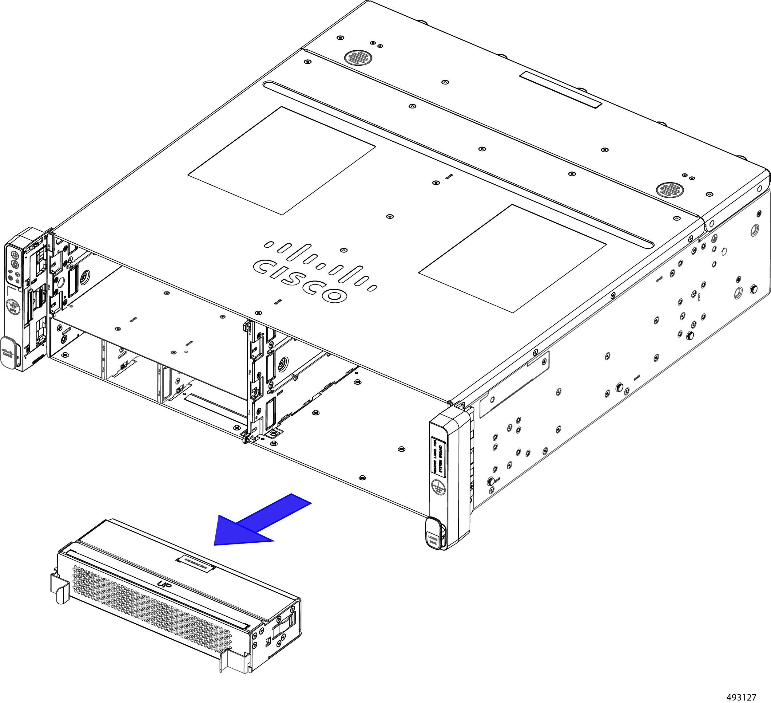
Removing a Node Blank
Node blanks are supported in chassis slots one through five, which are silkscreened onto the chassis.
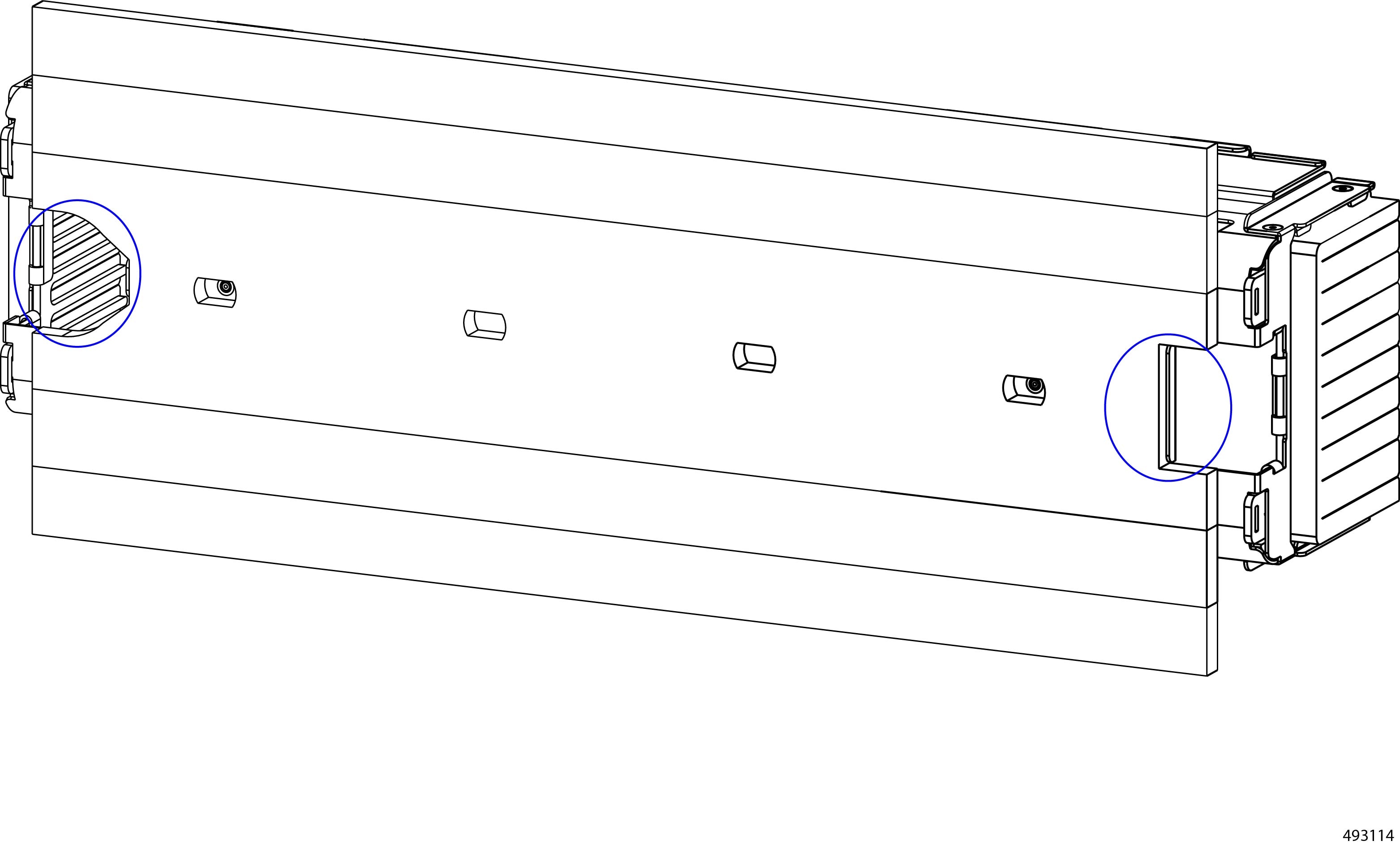
Node blanks are held in place by pressure through a tab on the left of each blank. Each node blank also has a handle on the right side of the node blank. The handle is stationary.
Use this procedure to remove a node blank. Removing a node blank is a toolless procedure. You can complete this procedure with your hands.
Procedure
|
Step 1 |
Locate the release tab on the left of the node blank. |
||
|
Step 2 |
Grasp the handle on the right side of the node blank. |
||
|
Step 3 |
While holding the handle, use your fingers to press the release tab inward.
|
||
|
Step 4 |
While holding the release tab inward, pull the node blank out of the chassis.
|
What to do next
Choose the appropriate option to fill the empty node slot:
-
Insert a compute node.
-
Reinsert a node blank.
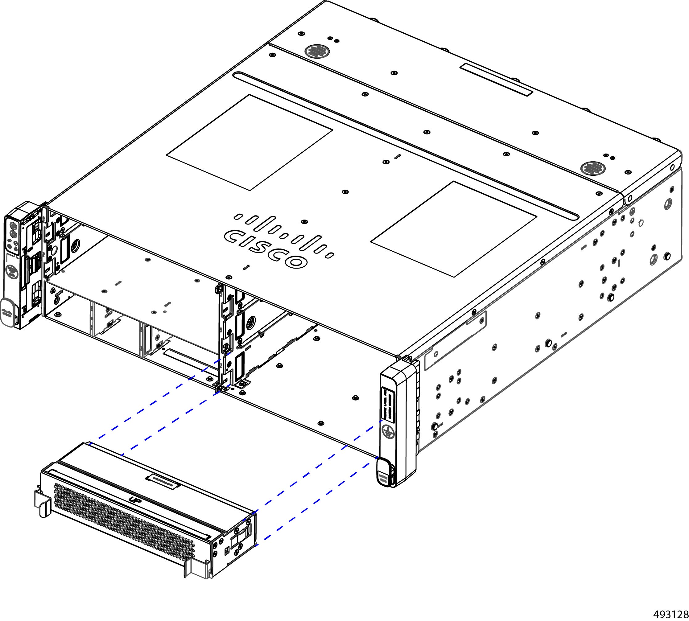
Installing a Node Blank
The chassis must have either a compute node or node blank covering any empty node slot.
Node blanks are held in place by pressure through a release tab on the left side of the node blank. To facilitate correct orientation, each node blank has the word UP printed on top.
Installing a node blank is a toolless procedure, so you can complete this task with your hands.
Use this task install a node blank.
Procedure
|
Step 1 |
Orient the node blank so that the word UP is facing up. |
|
Step 2 |
Align the node blank with the slot. |
|
Step 3 |
Holding the node blank level, slowly insert it into the chassis until it clicks in place.
|
Replacing the eCMC Node
Each of the Edge Chassis Management Controller (eCMC) nodes is replaceable. When you replace the module, you will disconnect it from the power backplane, so the node will power down. When you reinsert the module, the node automatically powers on after reconnecting to the power backplane.
Chassis Management Controller modules are assigned dedicated slots in the chassis. They must always be installed in those slots.
-
You cannot install a compute node into a Chassis Management Controller slot
-
You cannot install a Chassis Management Controller module into a standard compute node slot.
-
There is no restriction regarding the two Chassis Management Controller module slots. The primary and secondary modules can be installed in either slot.
The chassis can operate with only one Chassis Management Controller module installed, but for full redundancy and fault tolerance, it is strongly recommended that you operate the chassis with both modules installed.
Caution |
If the chassis is operating with only one Chassis Management Controller module installed, do not remove that module because it is acting as the primary. In this situation, install a secondary before removing the current primary to allow switch over to occur. |
To replace a Chassis Management Controller module, use the following tasks.
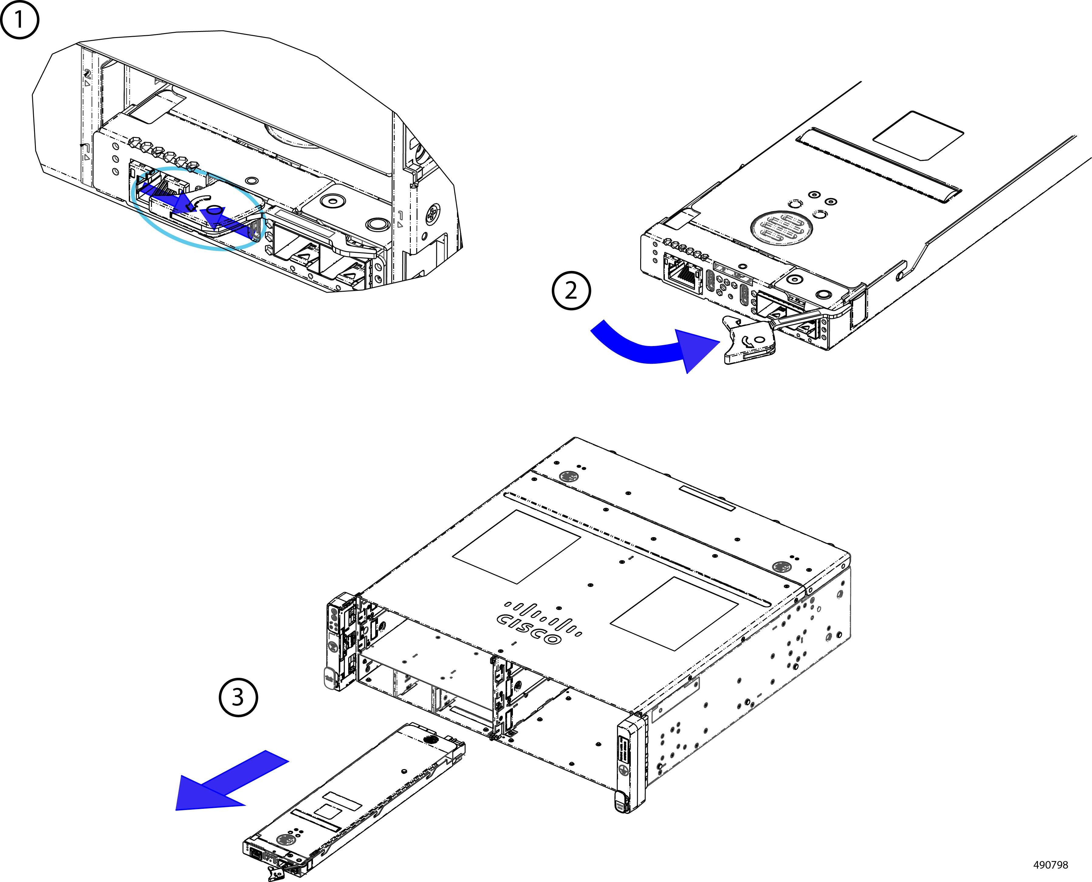
Removing the eCMC Node
Th eCMC ondes are deployed in pairs. For each chassis, there is a maximum of two, which are installed in the front of the chassis. The eCMC modules are easily accessible and removing them is a toolless task.
Removing an eCMC module is accomplished by releasing the ejector and sliding the node out of its slot bay in the chassis. You do not need to remove the top cover to perform this task.
When you remove the primary eCMC module, a switchover event occurs so that the secondary then becomes the primary.
Because the eCMC modules monitor and manage the other parts of the chassis and provide network connectivity, you should always keep at least one module installed to keep the chassis online and operating. If you need to replace both modules, replace the secondary first. When it is online and operating correctly, then replace the current primary.
Procedure
|
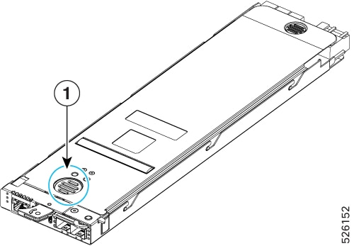
Step 1 |
Pinch the end of the ejector handle to disengage the locking mechanism. This step unlocks the ejector and allows it to move. |
||
|
Step 2 |
Gently swing the ejector to the open position. |
||
|
Step 3 |
Grasp the ejector and slide the eCMC module out of the chassis.
 |
||
|
Step 4 |
If you will not be reinstalling an eCMC module, attach a node blank to the unused slot.
|
Installing the eCMC Node
The Edge Chassis Management Controller (eCMC) nodes are installed in pairs. For each chassis, there is a maximum of two, which are installed in the front of the chassis. Chassis Management Controller modules are easily accessible and installing them is a toolless task.
Chassis management controller modules are keyed so that they cannot be installed incorrectly.
Because the Chassis Management Controller modules monitor and manage the other parts of the chassis and provide network connectivity, you should always keep at least one module installed to keep the chassis online and operating. If you need to replace both modules, replace the secondary first. When it is online and operating correctly, then replace the current primary.
Procedure
|
Step 1 |
Align the module with the slot in the chassis. The module is correctly aligned when the top cover is facing up. |
||
|
Step 2 |
Gently swing the ejector to the open position.
|
||
|
Step 3 |
Support the underside of the Chassis Management Controller module with your other hand and insert the Chassis Management Controller module into the slot.
|
||
|
Step 4 |
When the Chassis Management Controller module is almost fully installed, gently swing the ejector to the closed position. 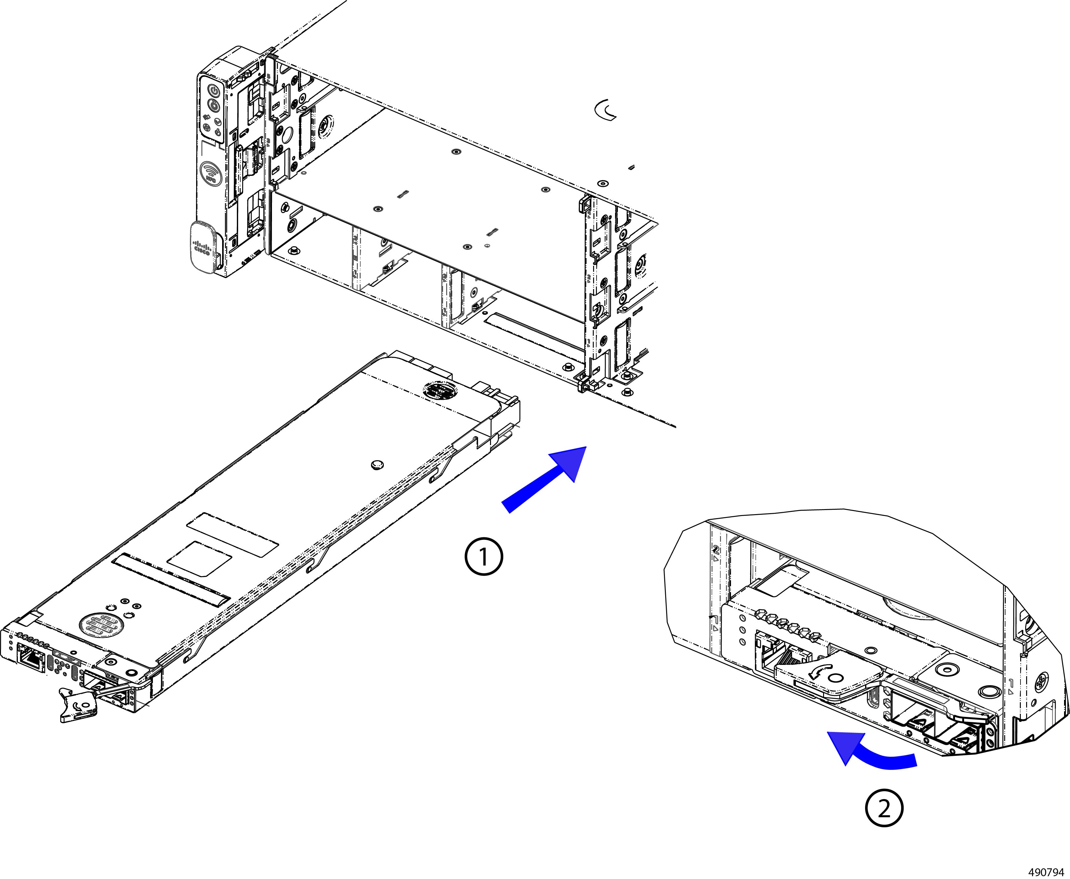 When fully closed, the ejector should click into place as the Chassis Management Controller module locks into place. |
Replacing the eCMC Boot-Optimized M2 Module
The chassis supports one internal boot-optimized RAID card, the Cisco M.2 NVMe BOOT RAID Controller. This card is a standard half-height, half-length PCIe x8 NVMe RAID adapter card.
The card is a boot-optimized RAID card, so it controls striping and mirroring (RAID 0/1) of data for chassis boot up, OS loading, and logging. Because the card is boot-optimized, it does not control user data I/O, such as reads and writes to the chassis EDSFF local storage.
To replace the eCMC's M.2 module, use the following procedures:.
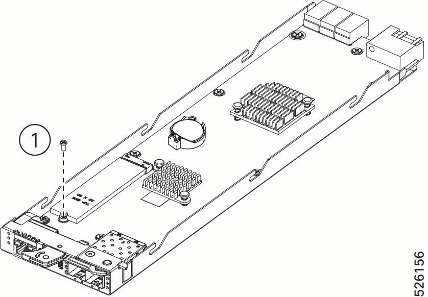
Removing the Boot Optimized M2 Module
You can remove the boot-optimized M.2 drive from the eCMC module.
Before you begin
If you have not already removed the Chassis Management Controller module, do so now.
Gather a #2 Phillips screwdriver.
Procedure
|
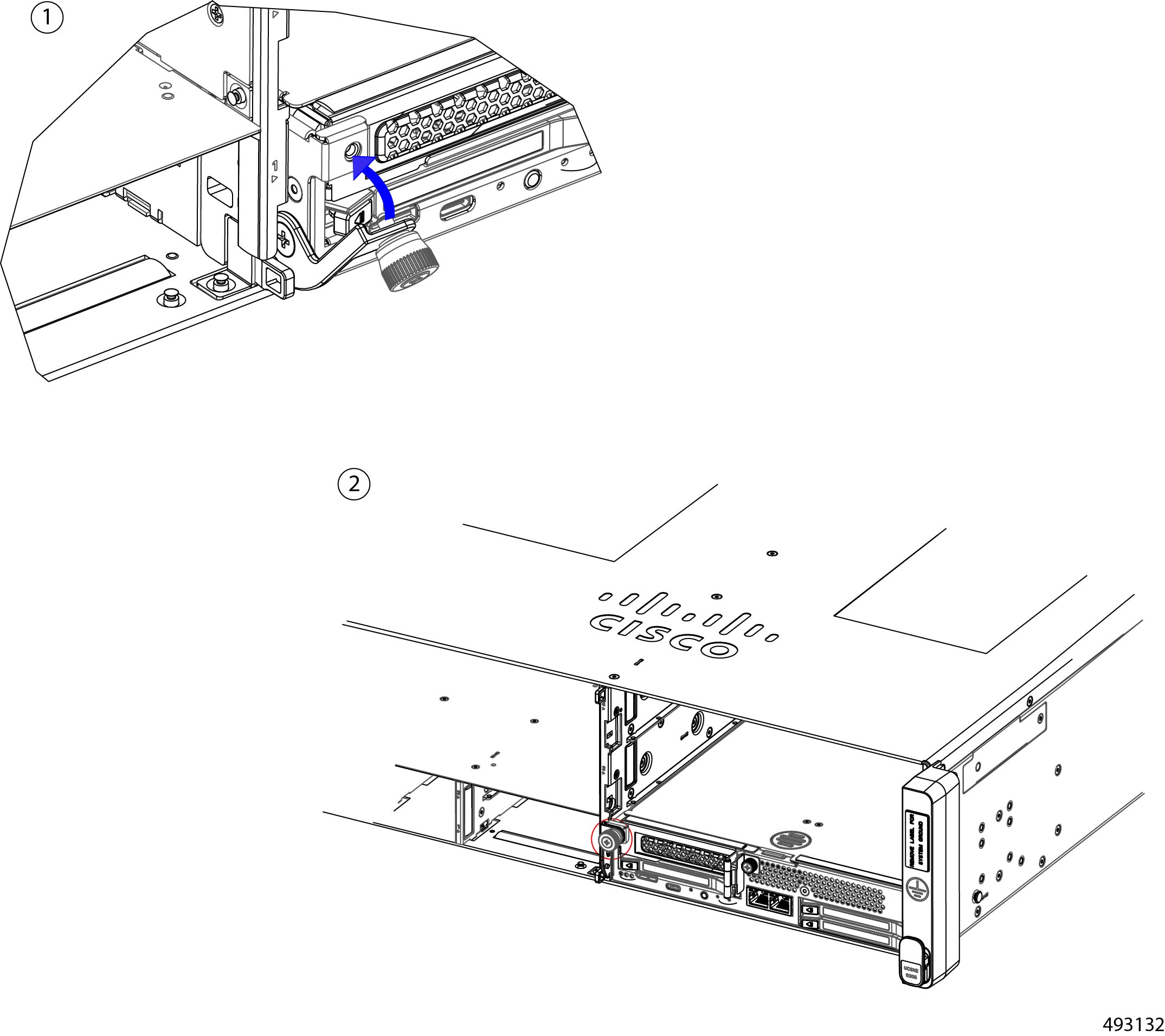
Step 1 |
If you have not already done so, remove the top cover. Go to Removing a Node Top Cover. |
|
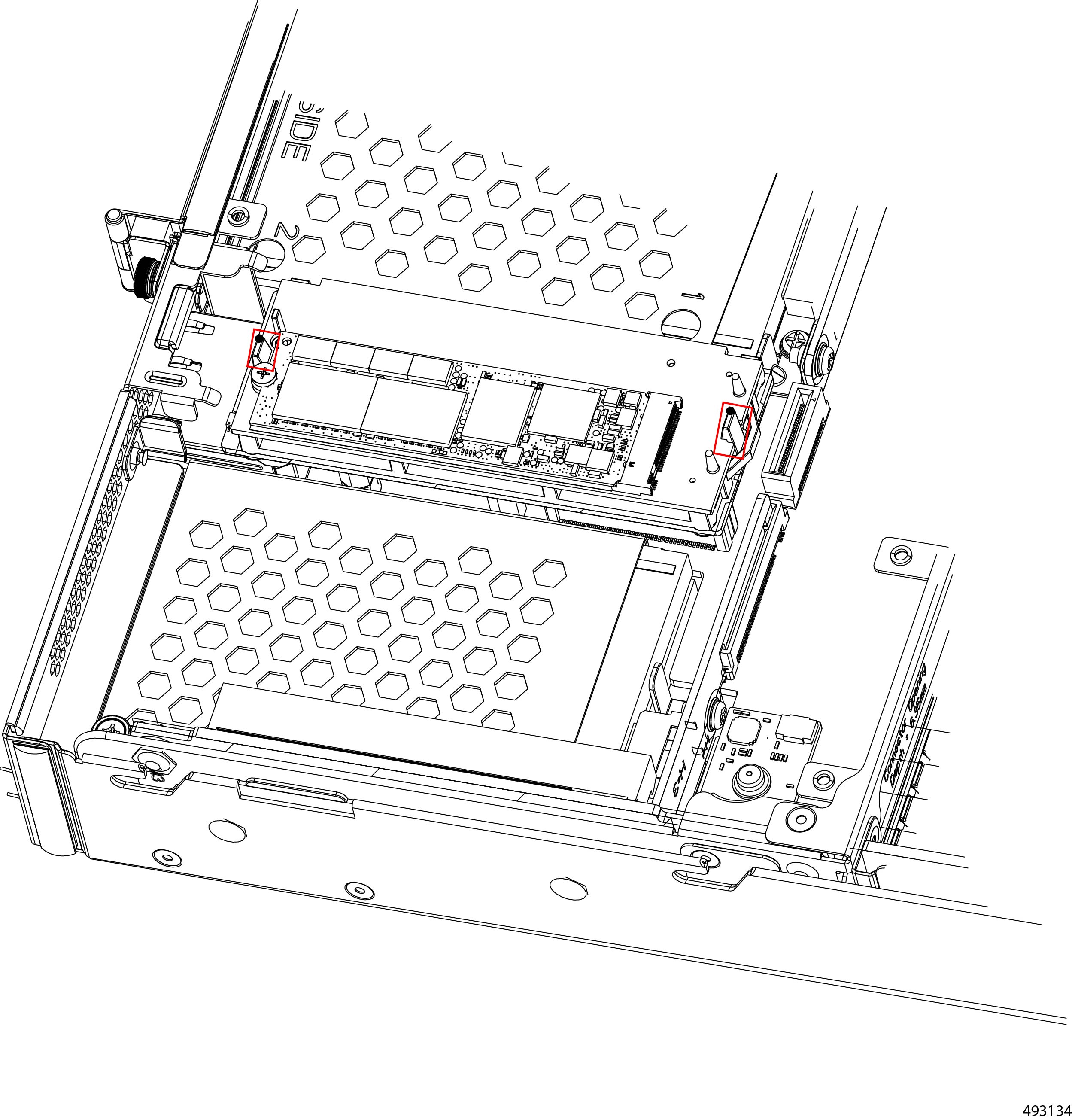
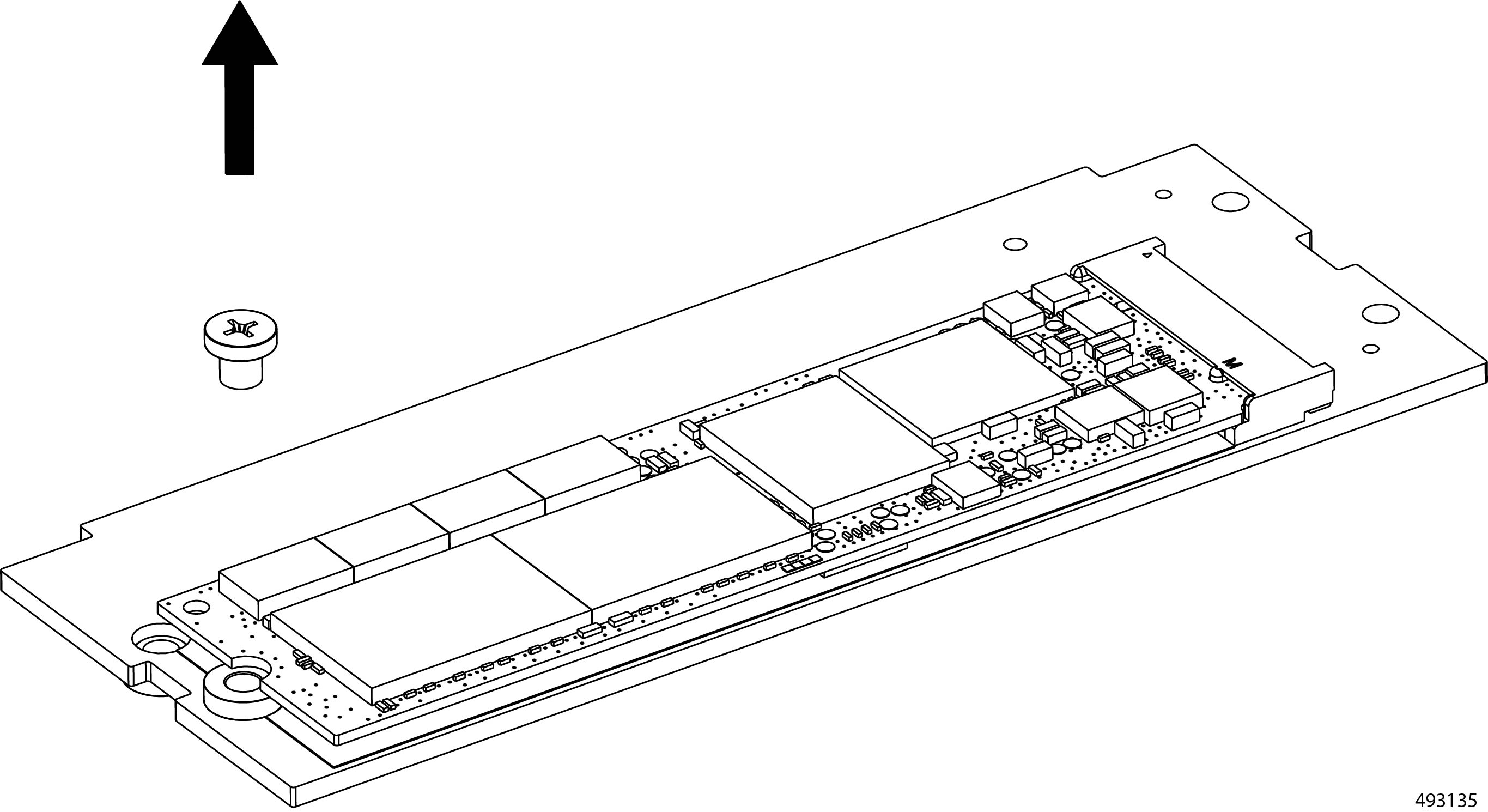
Step 2 |
Remove the M.2 drive from the module.
|
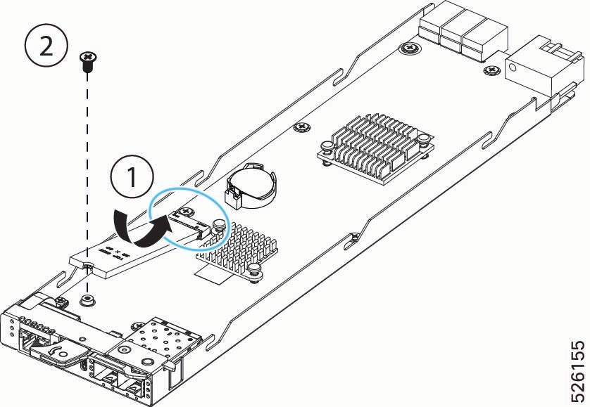
Installing the Boot Optimized M.2 Module
Use this task to install a boot-optimized M.2 module onto the Chassis Management Controller module.
Before you begin
The M.2 module installs onto the Chassis Management Controller module through a connector and a securing screw.
Procedure
|
Step 1 |
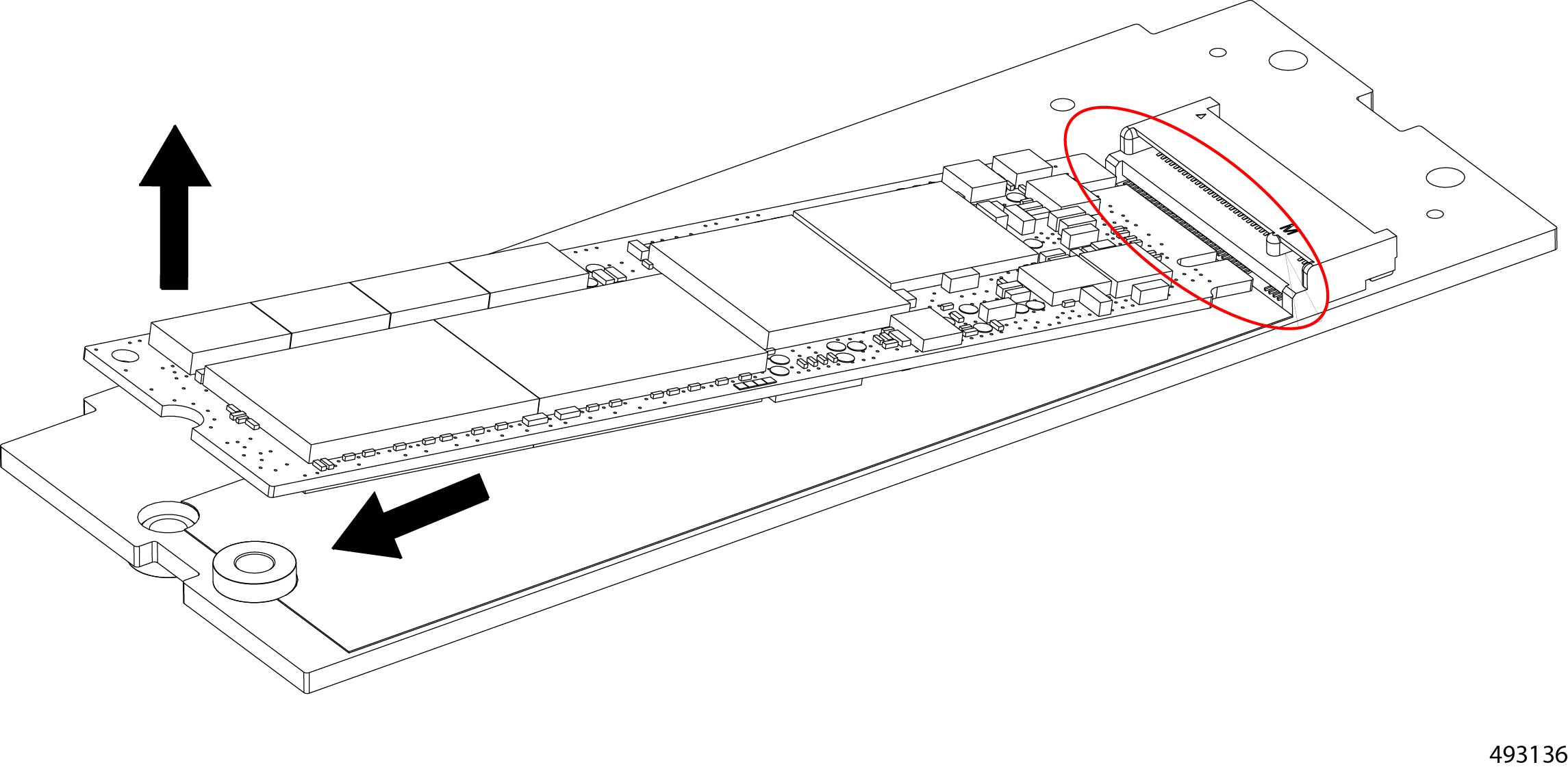
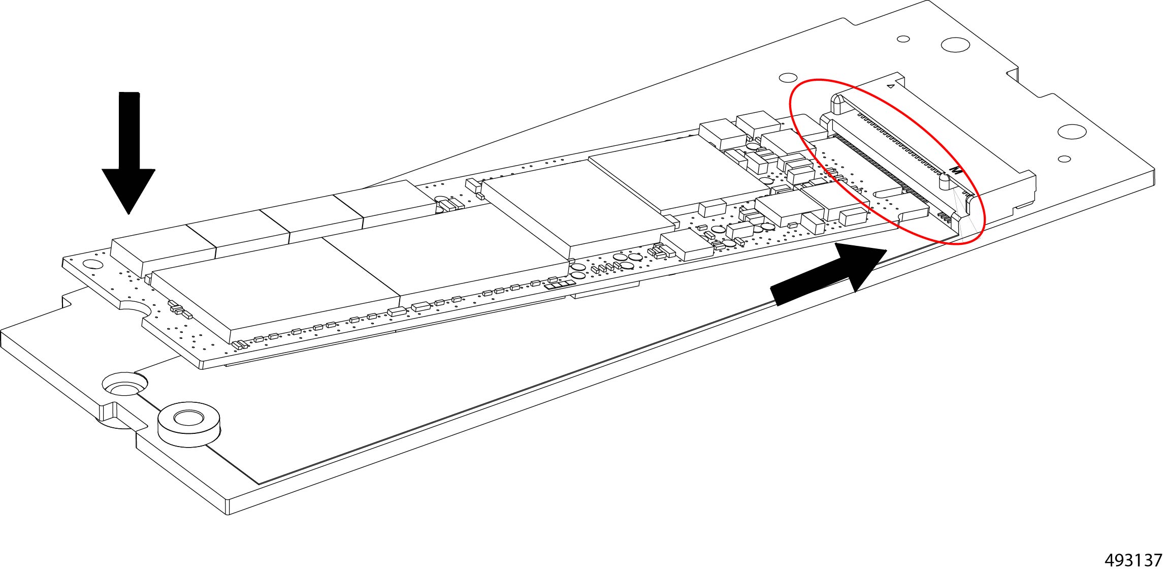
Align the M.2 drive with the connector. |
|
Step 2 |
Lower the M. 2 drive into place and install it into the connector. You will find it helpful to tilt the drive so that it connector correctly meets and seats into the motherboard socket. |
|
Step 3 |
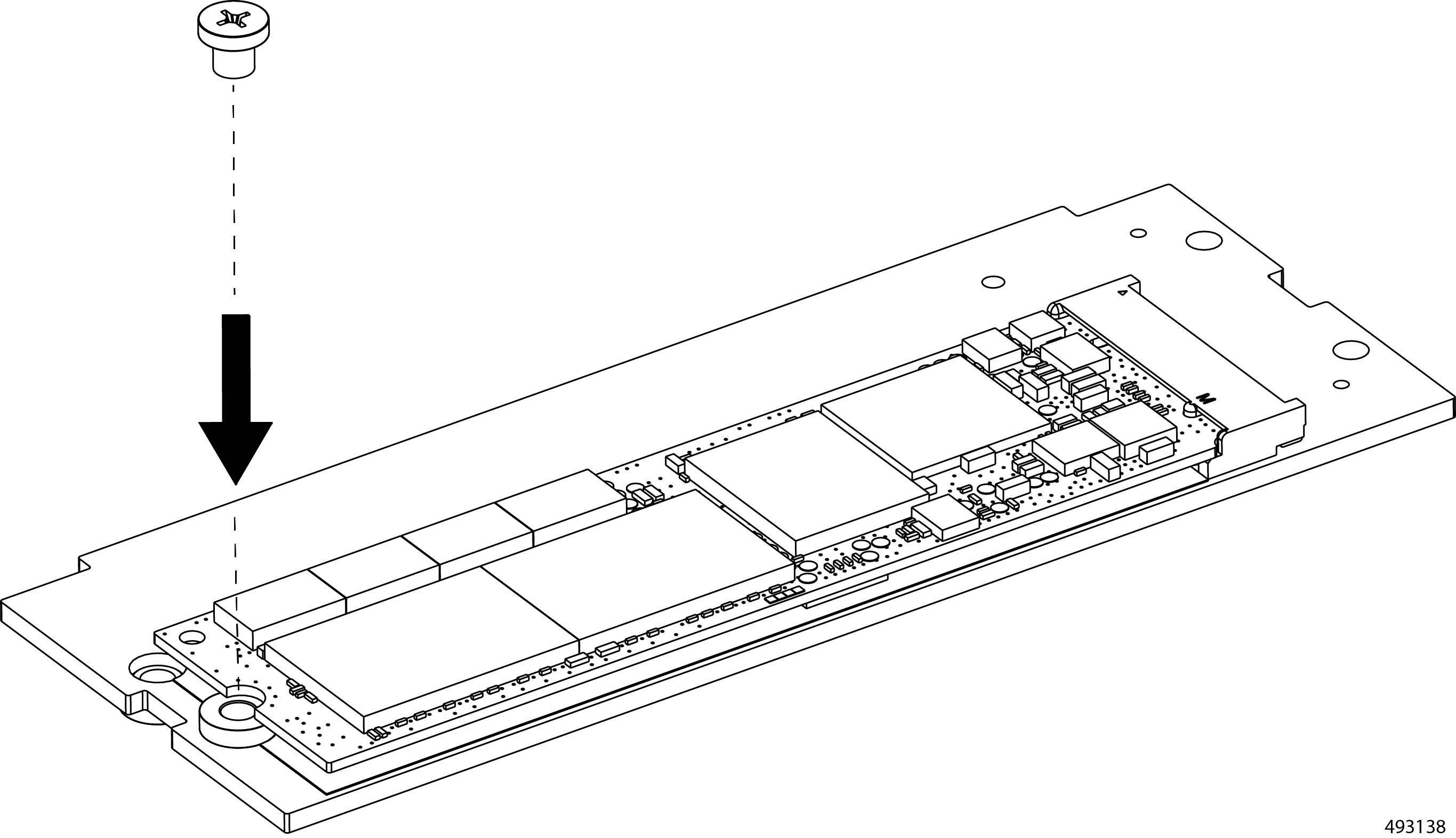
Using a #2 Phillips screwdriver, install and tighten the securing screw.
|
Replacing the Fan Modules
The chassis has five 80mm hot-swappable dual rotor fans modules located at the rear of the chassis. Each fan draws air from the cool aisle across the interior of the chassis. The heated exhaust air from the chassis is vented into the hot aisle.
Fan modules are individually hot-swappable, but a minimum of two fans is required to provide proper airflow and cooling. To avoid any overtemp condition for the chassis, we recommend that you replace a maximum of two fans simultaneously.
Two different fan replacement options are supported, either through direct access or by access through the rear top cover of the chassis. The option you choose depends on your ability to access the rear of the chassis.
-
Direct access to the fans is typically occurs when the chassis is installed in an open-frame rack with no rear wall.
-
Access through the rear top cover of the chassis typically occurs when the chassis is installed in a closed-frame rack (cabinet) with a rear wall the prevents easy access.
To replace fan modules, use the following tasks.
-
Direct access to fan modules.
-
Access to fans through the rear of the chassis.
Fan Replacement Options
The chassis offers two options for replacing fan modules: front-loading or through the rear cover. Each option depends on whether you can access the rear of the chassis where the fans are installed.
|
Equipment Rack |
Access to Rear of chassis? |
Service Method |
|---|---|---|
|
Four-Post Open Frame or Two-Post Open Frame |
Yes |
Either: or: |
|
Four-Post Closed Frame (cabinet) or Two-Post Closed Frame (cabinet) |
No |
Removing Rear-Loading Fan Modules
If you have rear access to your chassis, the fan modules are individually hot-swappable through the rear of the chassis. However, in some cases (for example, if the chassis is in a closed-frame equipment rack), you might not have access to the rear of the chassis. In this case, you must use the other fan replacement option. See Removing Fan Modules Through the Rear Cover.
To remove a fan module, you use the release buttons and the handle.
Before you begin
While performing fan replacement, be aware that at least three fans must be installed and operating in the chassis. For this reason, we strongly suggest that if multiple fan modules must be replaced, you should replace one fan at a time.
Procedure
|
Step 1 |
Using your fingers, simultaneously press on both the release buttons to disengage the locking mechanism. |
||
|
Step 2 |
While locking mechanism is disengaged, grasp the handle and slide the fan module straight out of the chassis.
|
Installing Rear-Loading Fan Modules
If you have rear access to your chassis, the fan modules are individually hot-swappable through the rear of the chassis. However, in some cases (for example, if the chassis is in a closed-frame equipment rack, you might not have access to the rear of the chassis. In this case, you must use the other fan replacement option. See Installing Rear-Loading Fan Modules.
There are no restrictions for installing fan modules. Any fan module can be installed in any fan module slot. However, if you will not be re-installing a fan module, you must insert a fan module blank to ensure proper airflow.
Fan modules are keyed so that they cannot be installed incorrectly, and they have no power switch. When a fan is installed, it will automatically power up.
To install a fan module, use the following procedure.
Procedure
|
Step 1 |
Align the fan module with the empty slot in the chassis. |
||
|
Step 2 |
Holding the fan module level, gently slide it in.
When the fan is completely installed, it will power up. |
Accessing the Rear of the Chassis
In some cases, you will not have direct access to the rear of the chassis. For example, in a closed-frame equipment rack (cabinet), sheet metal walls enclose the rear of the chassis, making it impossible to directly access the rear panel. Or, perhaps a wall, furniture or other obstruction prevents access to the rear of the chassis.
In cases such as these, you can access fan modules by removing the rear top cover of the chassis. Use this procedure to gain access to the top rear of the chassis.
Procedure
|
Step 1 |
Choose the appropriate option:
|
|
Step 2 |
For a four-post equipment rack, access the chassis. |
|
Step 3 |
For a two-post rack, access the chassis.
|
|
Step 4 |
Remove the fans at the rear of the chassis. |
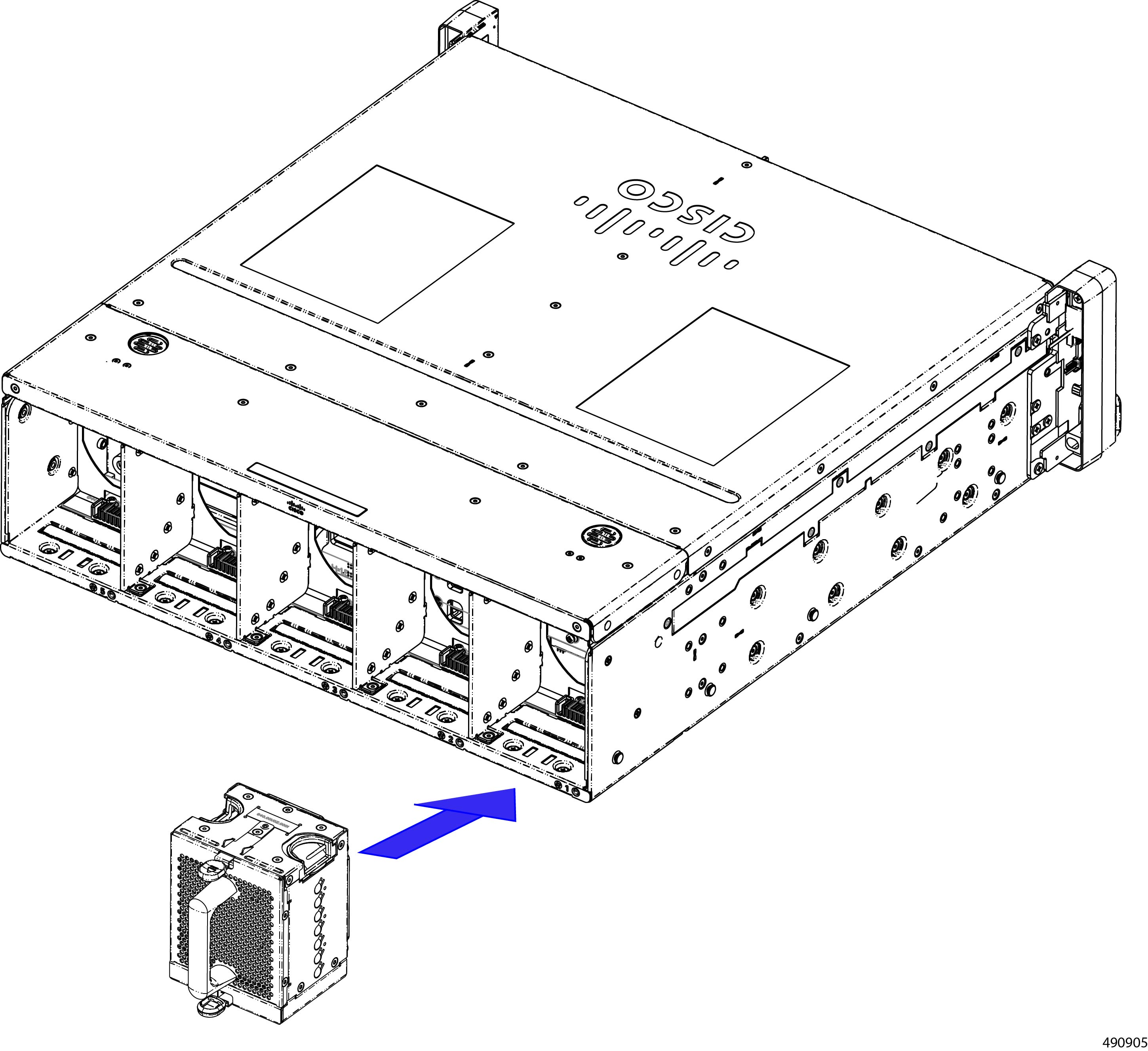
Removing Fan Modules Through the Rear Cover
-
If you do not have rear access to the chassis, you will need to replace fans by removing the rear top cover.
-
If you do have rear access to the chassis, you can replace the fan modules directly through the rear-loading option. See Removing Rear-Loading Fan Modules.
To remove a fan module through the top cover, use this procedure.
Note |
Depending on the ambient temperature and the load on the chassis, you might hear the other fans accelerate to maintain airflow when you remove the required fan. This behavior is normal. |
Before you begin
While performing fan replacement, be aware that at least three fans must be installed and operating in the chassis. For this reason, we strongly suggest that if multiple fan modules must be replaced, you should replace one fan at a time.
For this procedure, you will need a small ESD-safe work space to temporarily store the chassis rear top cover.
To complete this procedure, you will need clearance to work on the top rear of the chassis. See Accessing the Rear of the Chassis
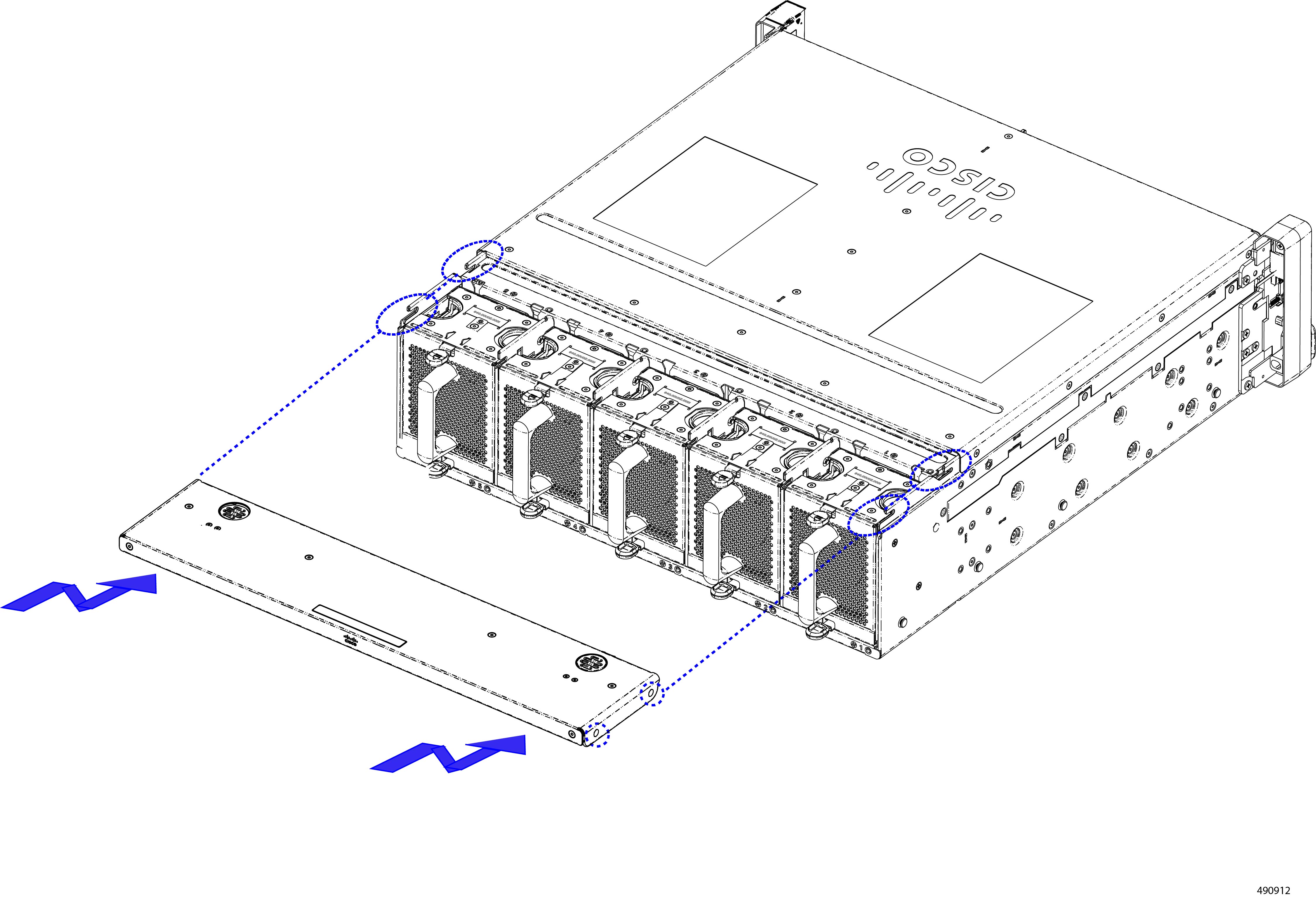
Procedure
|
Step 1 |
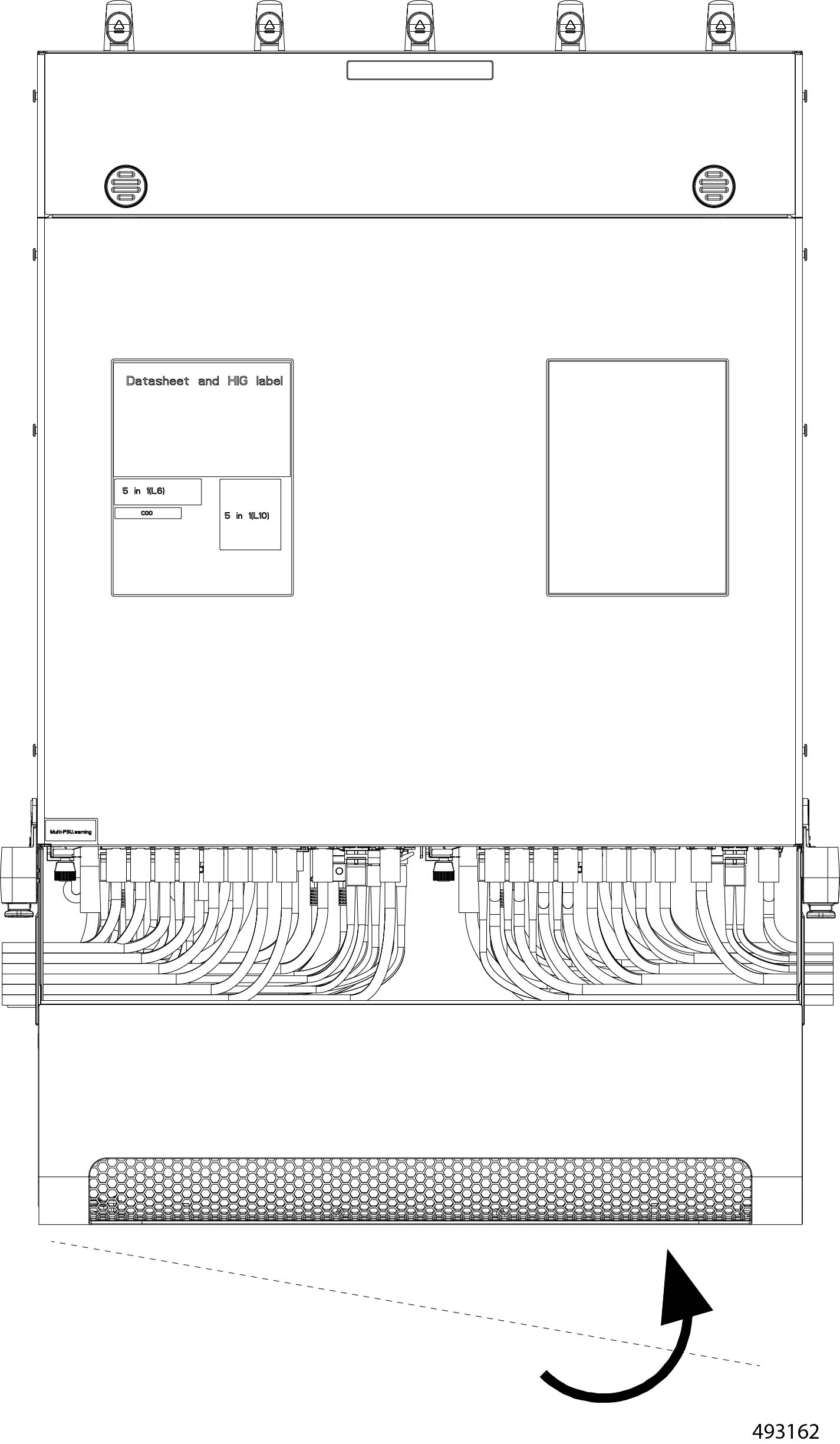
Remove the top rear cover of the chassis.
|
||
|
Step 2 |
Using your fingers, simultaneously press on both the release buttons to disengage the locking mechanism for each fan. |
||
|
Step 3 |
While locking mechanism is disengaged, grasp the handle and lift the fan module straight up to remove it from the chassis. 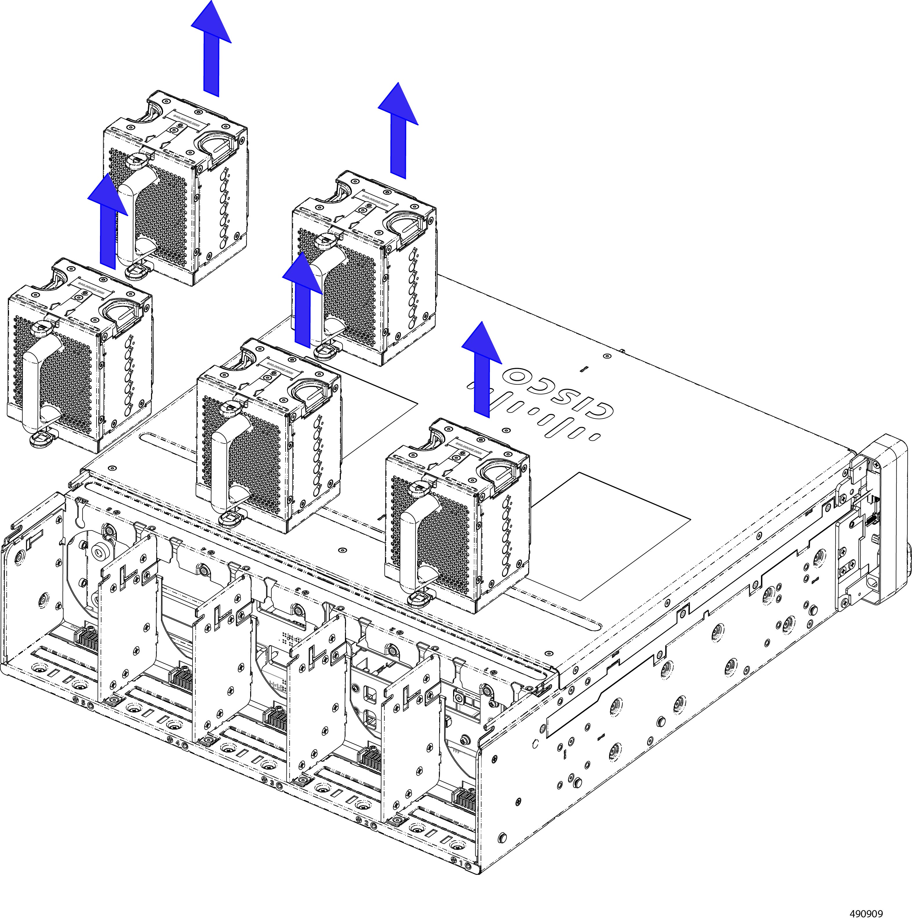
The illustration shows removing all fans at once, but a minimum of three fans is required to keep the chassis operational without causing an overtemp condition. We strongly recommend replacing only one fan at a time. |

Installing Fan Modules Through the Rear Cover
Fan modules can be installed through the top rear of the chassis for cases where you do not have direct access to the rear of the chassis.
Installing a fan is a toolless task.
There are no restrictions on which fan must be installed in which slot. For typical field-replacement procedures, you will install a fan into the same slot that the previous fan occupied. However, you can install any fan into any slot.
Attention |
Do not operate the chassis with an empty fan slot. If you remove a fan module and will not install another fan into that slot, cover the slot with a fan module blank. |
Procedure
|
Step 1 |
Align the fan with its slot. |
||
|
Step 2 |
Holding the fan module vertical, lower it straight down into the slot.
 |
||
|
Step 3 |
Check the bottom and sides of the slot to verify that the fan is seated flush into the slot. If the fan is not correctly seated, it can obstruct installing the top rear cover. |
||
|
Step 4 |
When the fan is correctly installed, attach the top rear cover.
|
Replacing the Power Supplies
The chassis features two power supply units (PSUs) in the front of the chassis. Each PSU supplies 2400W of AC power (UCSXE-PSU-2400W), and each is hot swappble.
A PSU is numbered either one or two based on the slot that it occupies. PSU numbering is right to left.
-
PSU 1 is installed in slot 1 (the right slot)
-
PSU 2 is installed in slot 2 (the left slot)
PSUs are interchangeable, so you can install either PSU in any slot.
PSUs support 1+1 power redundancy (grid), so the chassis can operate on only one PSU. However, for full power redundancy and fault tolerance, we strongly recommend having both PSUs installed during normal operation.
As a best practice, we recommend inserting a PSU within one minute of removal.
To replace a PSU, use the following tasks.
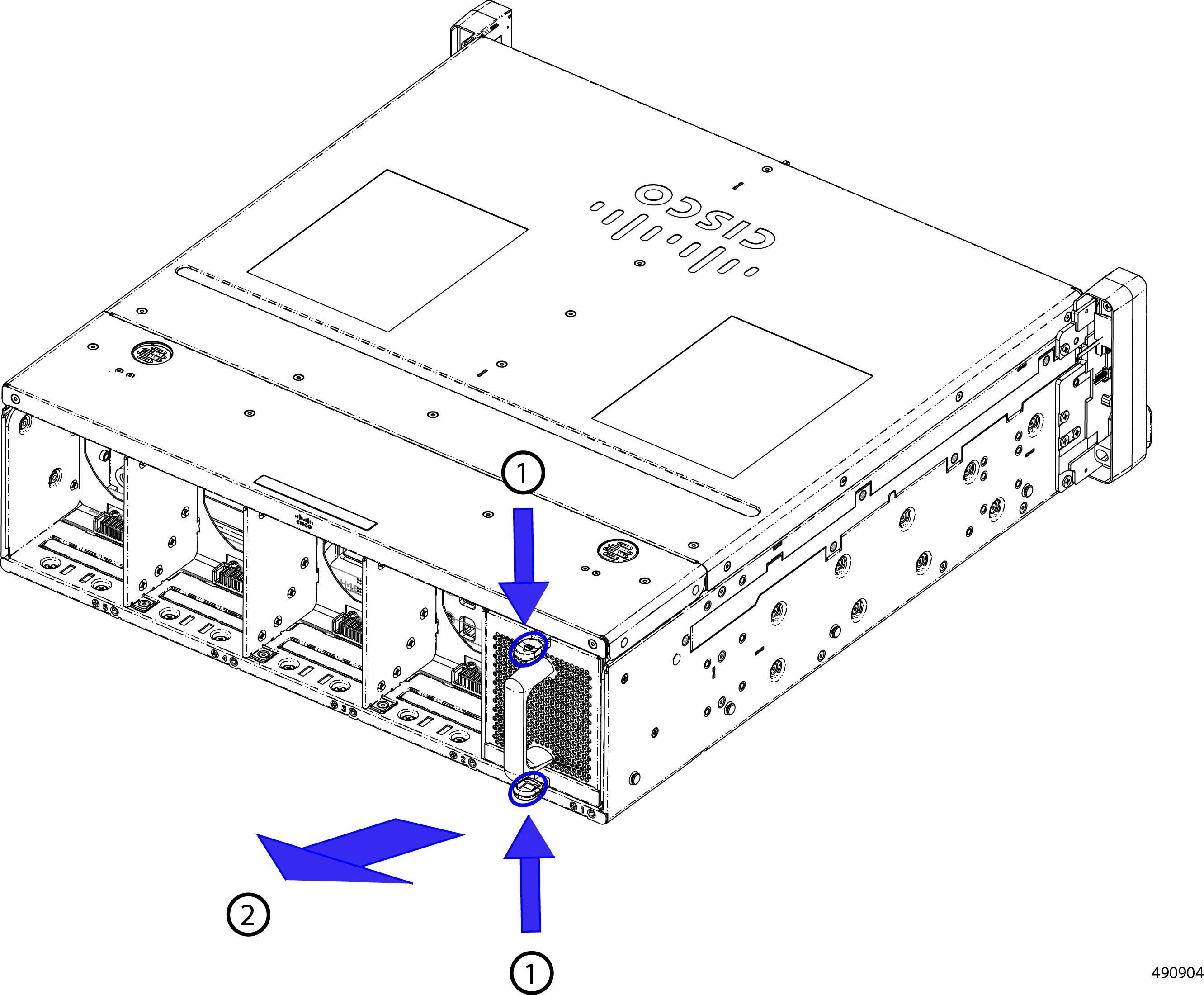
Removing Power Supply Units
PSUs are installed in the front of the chassis. They support 1+1 power redundancy and are hot swappable. If both PSUs need to be replaced, remove and install one at a time.
Procedure
|
Step 1 |
Disconnect facility power cables that are plugged in to the PSU. |
||
|
Step 2 |
Grasp the PSU handle and using your finger, press the release tab inward (toward the handle) to disengage the locking mechanism |
||
|
Step 3 |
While the lock is disengaged, pull the PSU straight towards you and slide it partially out of the chassis. |
||
|
Step 4 |
While the PSU is still partially installed in the chassis, place your other hand on the underside of the PSU to support its weight.
|
||
|
Step 5 |
Completely remove the PSU from the chassis.
|

Installing Power Supply Units
Use this procedure to install a PSU. There are no restrictions on the slot (1 or 2) into which a PSU can be installed.
PSUs are keyed, so they cannot be installed incorrectly.
PSUs have no power switch, so the PSU automatically powers on when it is installed and connects to chassis power.
Procedure
|
Step 1 |
Place your other hand on the underside of the PSU to support its weight. |
||
|
Step 2 |
Orient the PSU correctly and align it with its slot. The PSU is oriented correctly when the release tab is on the right. |
||
|
Step 3 |
Slide the PSU into the slot.
|
||
|
Step 4 |
Holding the handle, push the PSU all the way into the chassis to fully seat it into the chassis.  |
||
|
Step 5 |
Reconnect any facility power cables that need to be plugged into facility power. |
 Feedback