Servicing the Node

This chapter contains the following topics:

Servicing the Node

The Cisco UCS XE150c M8 Compute Node contains components that can be serviced after the node is removed from the Cisco UCS XE9305 chassis. The sheet-metal top cover protects the internal components and maintains the airflow path. Remove the cover only when servicing an internal component, and reinstall the cover before returning the node to service.


Important


Only trained personnel should remove the compute node or service its internal components.


Serviceable Component Locations

The following components are covered by the service procedures in this chapter.

Table 1. Serviceable Component Locations

Component

Location

Access

Tool

Top Cover

Top of compute node

Release button and retention pins

No tool required

E3.S NVMe Drive

Front of the compute node

Release latch by pressing button

No tool required

M.2 RAID Controller and M.2 SSDs

Internal motherboard

Remove top cover

Remove GPU tray module

#1 Phillips; retaining screw: 2.8–3.7 in-lb

DIMM

Internal Motherboard

Release latch on DIMM socket

No tool required

PCIe Adapter

Internal Motherboard

Remove screws

GPU

Under the top cover

Remove top cover

Trusted Platform Module

Internal Motherboard

Remove screws

Pre-Installation Requirements and Considerations

Site Preparation Requirements

Before installing the compute node, be aware of the following:

  • Power Infrastructure: Ensure the Cisco UCS XE9305 Chassis is properly connected to a stable power source compatible with the 12 to 54 VDC input requirements. Verify that the total PoE power budget (up to 360W) is accounted for in your power planning.

  • Grounding: The Cisco UCS XE9305 Chassis must be properly grounded to prevent electrostatic discharge (ESD) damage to the high-density ARM v9 SOC and FPGA components.

Installation Caveats and Considerations

Datacenter administrators should be aware of the following operational considerations:

  • Hot-Swap: The Cisco UCS XE150c M8 Compute Node supports hot-swap functionality. However, ensure the host chassis is powered and stable before engaging the node.

  • ESD Precautions: When you handle the compute node, especially when the top cover is removed and the motherboard, and their components are accessible, always wear an ESD-preventive wrist strap during installation or removal.

Component Replacement Warnings

For component replacement, be aware of the following.


Note


An instructed person is someone who has been instructed and trained by a skilled person and takes the necessary precautions when working with equipment.

A skilled person or qualified personnel is someone who has training or experience in the equipment technology and understands potential hazards when working with equipment.


Warning


Only an instructed person or skilled person should be allowed to install, replace, or service this equipment. See statement 1089 for the definition of an instructed person or skilled person.


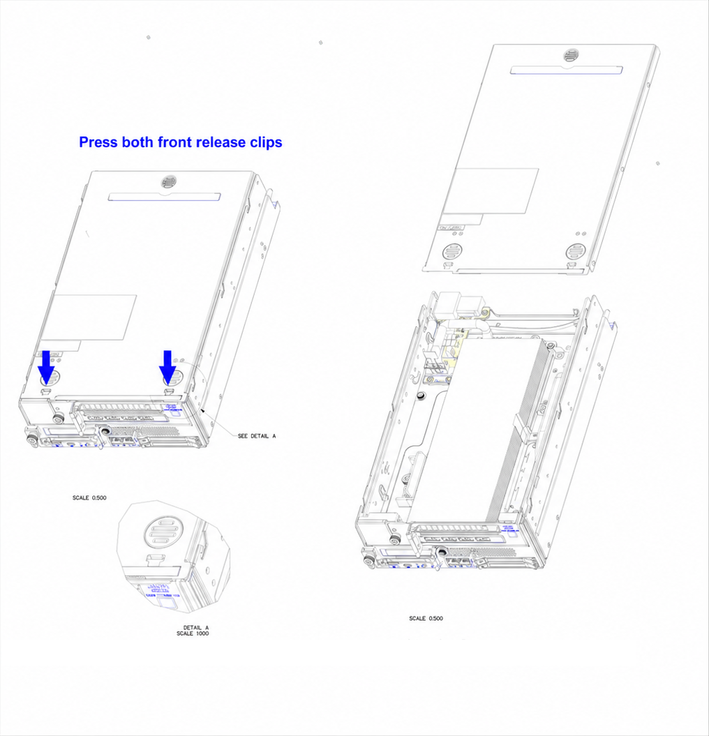
Removing a Node Top Cover

Use this task to remove the node top cover.

Before you begin

To access the node top cover, the node must be removed from the chassis. When the node is removed from the chassis, the node is disconnected from the power backplane, so the node is powered off.

Procedure


Step 1

Press both the front release clips on the node top cover.

Step 2

While holding the release button down, slide the cover toward the back of the node. Lift the back end of the cover so the retention pins clear the grooves on top of the node.


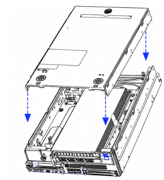
Installing a Node Top Cover

Use this task to install a node top cover.

Before you begin

After any service procedures are complete, you must install the node top cover before re-installing it into the chassis.

When the node is re-installed, it will power on after successfully connecting to the power backplane.

Procedure


Step 1

Lower the top cover onto the node.

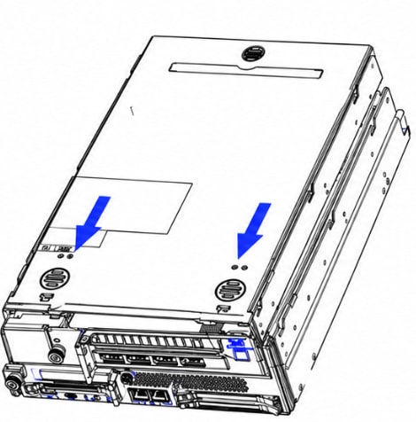
Step 2

Slide the front end of the cover under the sheet-metal edge on the node. Make sure the retention pins slide into the grooves on top of the node.

Step 3

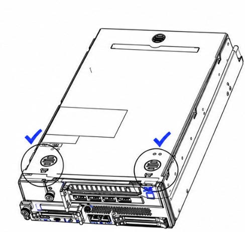
Continue sliding the cover until the release button engages, indicating that the cover is locked.

The node powers on after it is fully inserted into the chassis and connects to the power backplane.


What to do next

Choose the appropriate option:

  • If you will return the node to service, insert it back into the chassis and connect cables.

    Go to Installing a Compute Node.

  • If you will not install any node in the slot previously occupied by the node, install a blank filler panel.

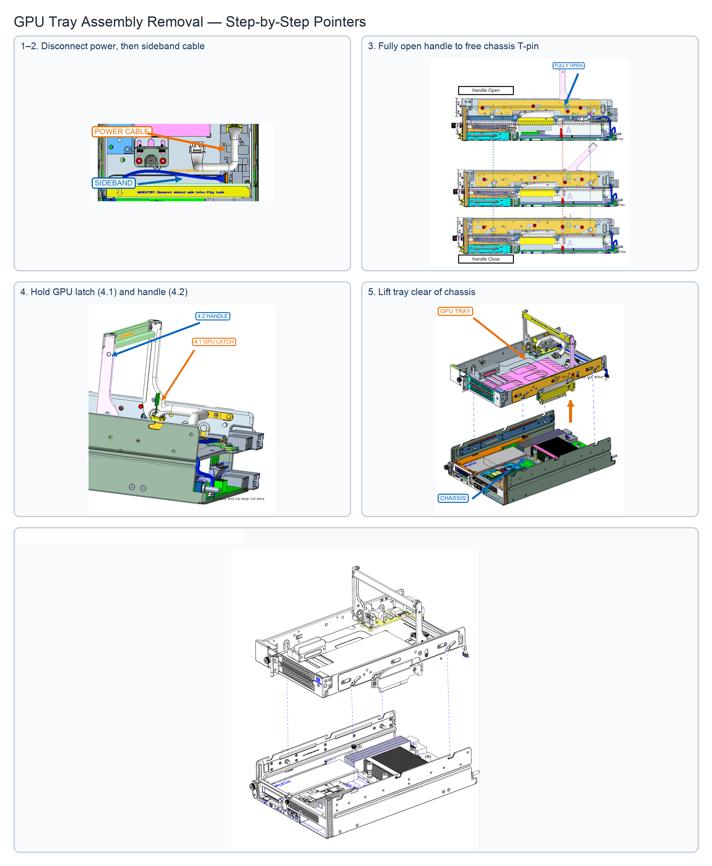
Removing GPU tray assembly

Before you begin

Procedure


Step 1

Disconnect the power cable from the GPU power board.

Step 2

Disconnect the sideband cable from the GPU power board and main board. It must be disconnected before you lift the handle.

Step 3

Open the GPU tray handle fully to disengage it from the chassis T-pin. If it is not fully open, the tray will remain engaged; don’t force it.

Step 4

Support the tray at the GPU latch (4.1) and handle (4.2). Don’t lift it by the thumbscrew.

Step 5

Lift the tray clear of the chassis.


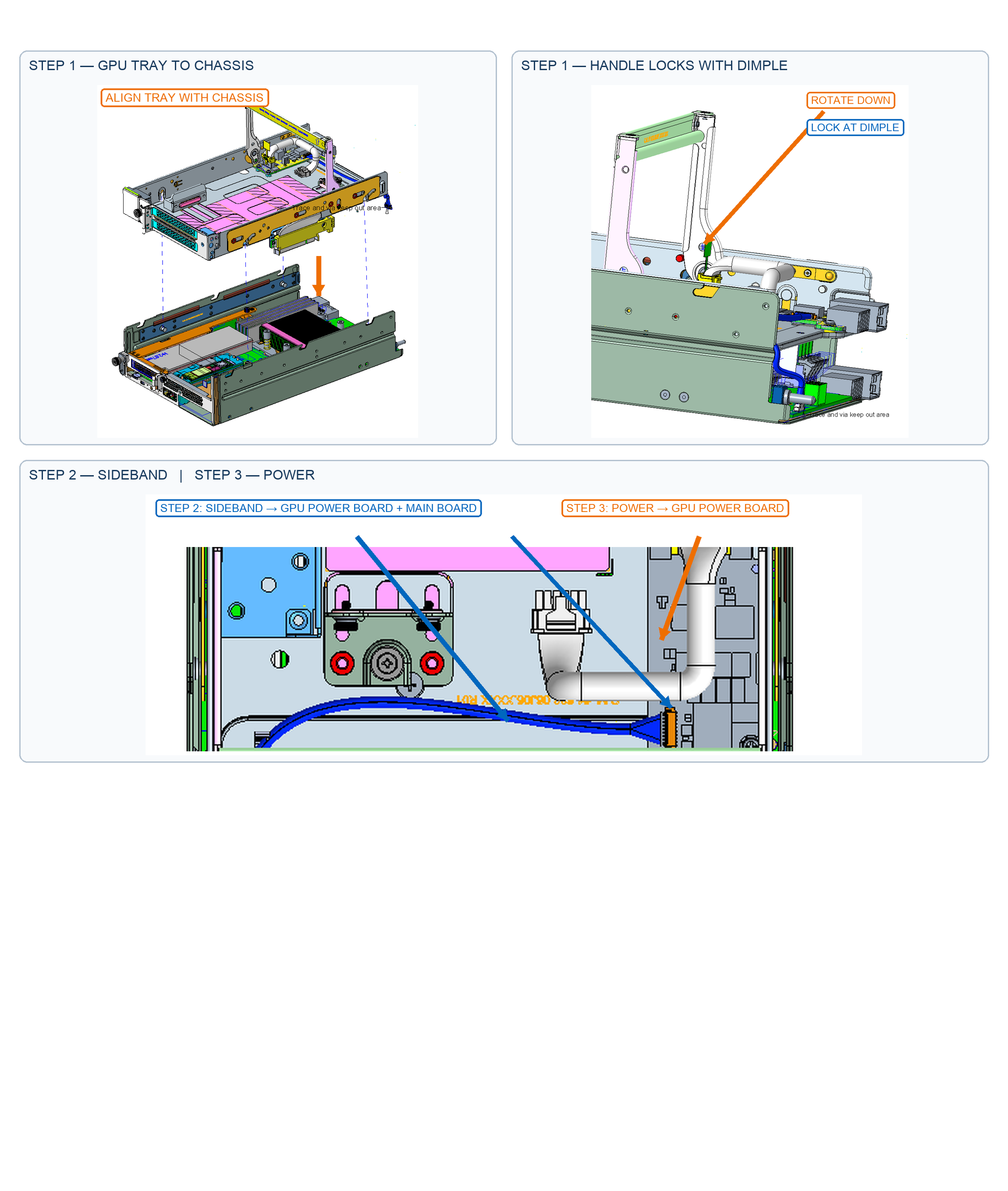
Installing GPU tray assembly

Before you begin

Procedure


Step 1

With the handle fully open, align the GPU tray with the chassis and seat it.

Push and rotate the handle down until it locks with the dimple.

Step 2

Connect the sideband cable to the GPU power board and main board.

Step 3

Connect the power cable to the GPU power board.


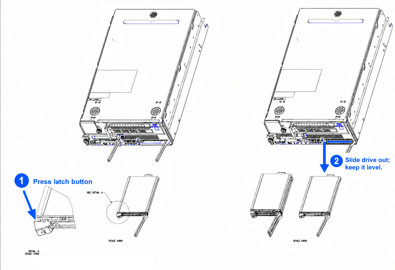
Removing an E3.S Drive

Use this task to remove an E3.S drive.

Before you begin

The E3.S drive is hot-swappable and can be removed from the front of the compute node without removing the top cover.

Procedure


Step 1

Press the E3.S latch button.

The ejector latch opens.

Step 2

Hold the open latch and pull the drive out.

Keep the drive level and support its underside as needed.


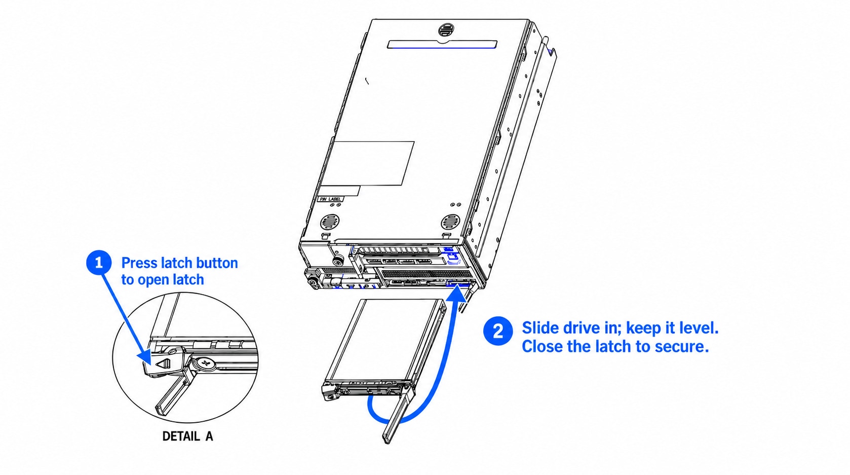
Installing an E3.S Drive

Use this task to install an E3.S drive.

Before you begin

E3.S drives are front-loading and hot-swappable. You do not need to remove the node’s top cover.

Procedure


Step 1

From the front of the node, press the latch button shown in Detail A to open the ejector latch.

Step 2

Align the drive with the bay. Keep it level, support its underside, and slide it straight in until seated.

Step 3

Close the ejector latch to secure the drive.


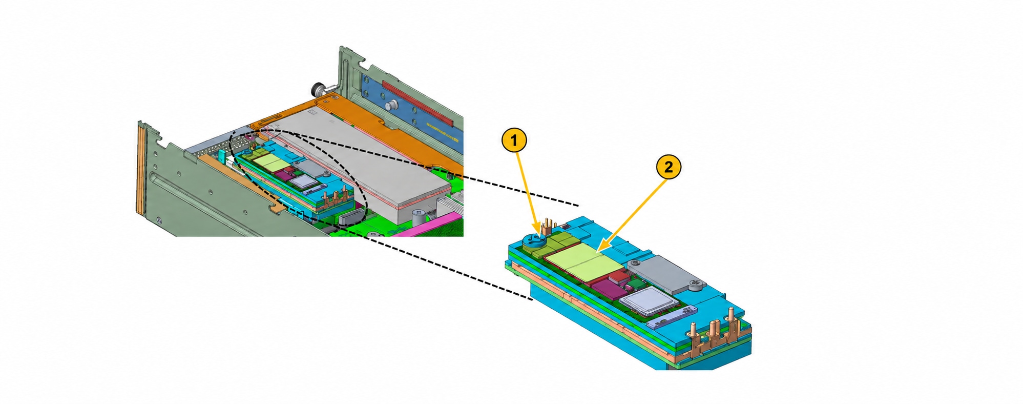
Removing the M.2 SSDs

Use this task to remove the M.2 SSDs.

Before you begin

The compute node must be powered off before you replace the M.2 SSD; hot-plug replacement is not supported. Remove the compute node from the chassis. You need a #2 Phillips screwdriver to remove the SSD.

Procedure


Step 1

Remove the M.2 SSD retaining screw.

Step 2

Remove the SSD by lifting slightly and sliding it out.


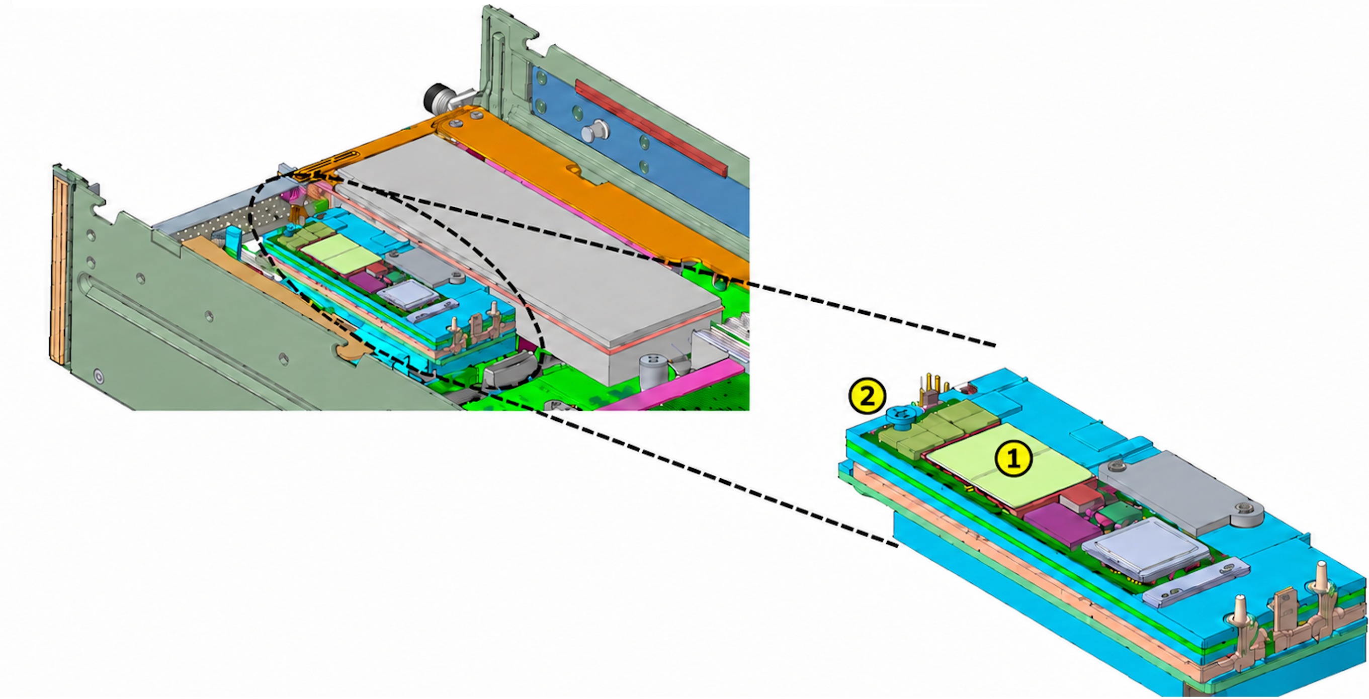
Installing the M.2 SSDs

Use this task to install the M.2 SSDs.

Before you begin

You need a #2 Phillips screwdriver to install the M.2 SSDs.

Procedure


Step 1

Insert SSD by sliding into the connector at an angle.

Step 2

Install and tighten the M.2 SSD screw to 2.55–3.45 kg-cm.


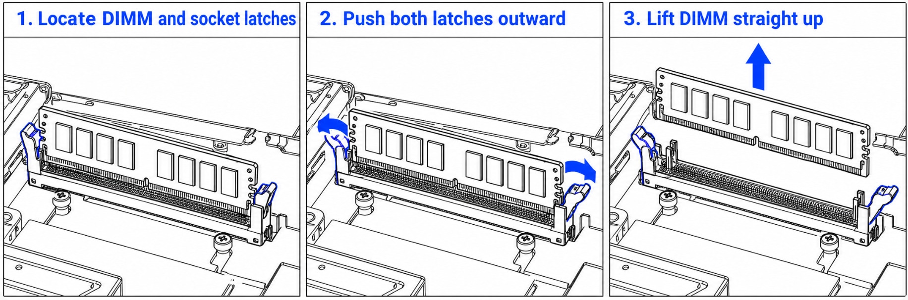
Removing the DIMM

Use this task to remove the DIMM.

Before you begin

Remove the compute node from the chassis and remove its top cover to access the DIMMs.

Procedure


Step 1

Locate the DIMM and the connector latches at both ends of its socket.

Step 2

Simultaneously push both connector latches outward to open the socket.

Step 3

When the latches are open, grasp the DIMM and lift it straight up to remove it from the socket.


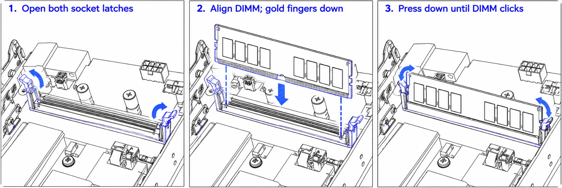
Installing the DIMM

Use this task to install the DIMM.

Before you begin

DIMM installation is tool-less. The compute node must be removed from the chassis to access its DIMM sockets.

Remove the node’s top cover and identify the correct empty socket for your memory configuration. For supported DIMM population, see the memory population rules in the guide.

Procedure


Step 1

Push the connector latches at both ends of the socket outward to open them.

Step 2

Align the DIMM with the socket, with the golden fingers pointing down.

Step 3

Insert the DIMM into the socket and gently press down until it clicks into place.

Step 4

After installing the required DIMMs, reinstall the node in the chassis.


Removing a PCIe Adapter

Use this task to remove a PCIe adapter.

Before you begin

The PCIe adapter is installed in the left PCIe cage when facing the compute node.

Have a #2 Phillips screwdriver available.

Procedure


Step 1

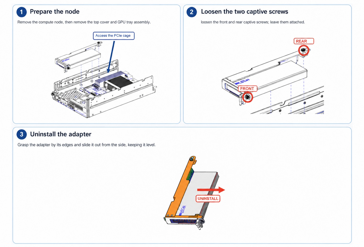
Remove the compute node from the chassis. Then remove the top cover and the GPU tray assembly. For detailed instructions, refer to Removing a Node Top Cover and Removing GPU tray assembly.

Step 2

Release the two captive thumbscrews that secure the PCIe cage. Hold the cage by its touch points and lift it off the node.

Step 3

Grasp the adapter by its edges and slide it out from the side, keeping it level.


Installing a PCIe Adapter

Use this task to install a PCIe adapter.

Before you begin

The adapter must be a supported HHHL PCIe Gen5 x16 card. Remove the compute node from the chassis before installing the card.

Have a #2 Phillips screwdriver and a torque driver available for reinstalling the PCIe cage.

Procedure


Step 1

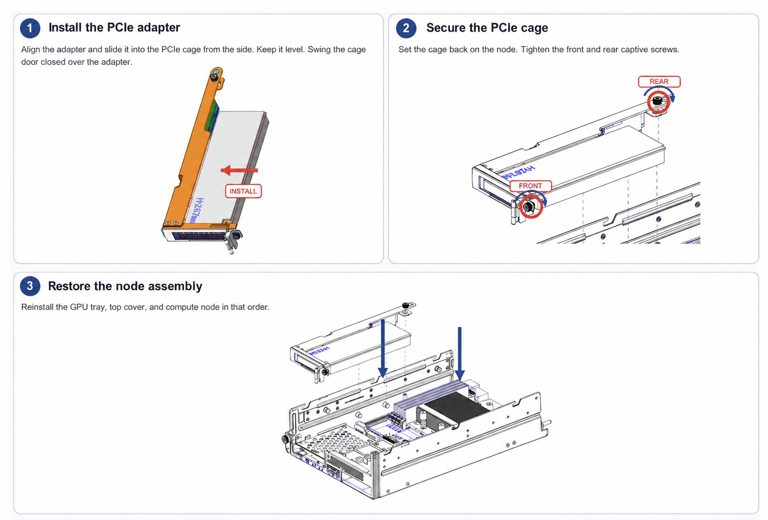
Align the PCIe adapter and slide it into the PCIe cage from the side. Keep it level. Swing the PCIe cage door open.

Step 2

Tighten the front and rear captive screws until snug.

Step 3

Reinstall the GPU tray, top cover, and compute node in that order.


Removing a GPU

Use this task to remove a GPU.

Before you begin

Remove the compute node from the chassis and remove its top cover to access the GPU cage.

Have a #2 Phillips screwdriver ready.

Procedure


Step 1

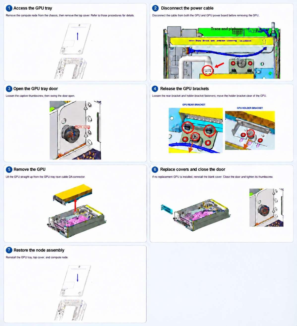
Remove the compute node from the chassis, then remove the top cover.

Step 2

Disconnect the cable from both the GPU and GPU power board before removing the GPU.

Step 3

Loosen the captive thumbscrew of the GPU tray and swing the door open.

Step 4

Loosen the rear-bracket and holder-bracket fasteners; move the holder bracket clear of the GPU.

Step 5

Lift the GPU straight up from the GPU-tray riser-cable DA connector.

Step 6

If no replacement GPU is installed, re-install the blank cover. Close the door and tighten the thumbscrew.

Step 7

Re-install the GPU tray, top cover, and compute node.


Installing a GPU

Use this task to install a GPU.

Before you begin

The compute node supports an optional graphics processing unit (GPU) in the right PCIe cage. The GPU must be a supported half-height, half-length (HHHL) card. Remove the compute node from the chassis and its top cover before installation. Have a #2 Phillips screwdriver and a torque driver available.

Do not operate the compute node with an empty PCIe slot. If you do not install a GPU, install a PCIe filler blank.

Procedure


Step 1

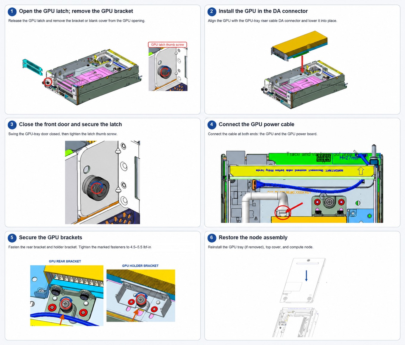
Open the GPU latch and remove the GPU bracket or blank cover.

Step 2

Align the GPU with the tray’s riser cable DA connector and lower it into place.

Step 3

Close the front door and tighten the latch thumb screw.

Step 4

Connect the power cable to both the GPU and the GPU power board.

Step 5

Fasten the GPU rear bracket and holder bracket. Tighten the specified fasteners to 4.5–5.5 lb-in (5.17–6.32 kg-cm).

Step 6

Reinstall the top cover and return the compute node to the chassis.


Removing the Trusted Platform Module

Use this task to remove the Trusted Platform Module.

Before you begin

Gracefully power off the compute node. Remove the node from the chassis and remove its top cover using the approved procedures.

Procedure


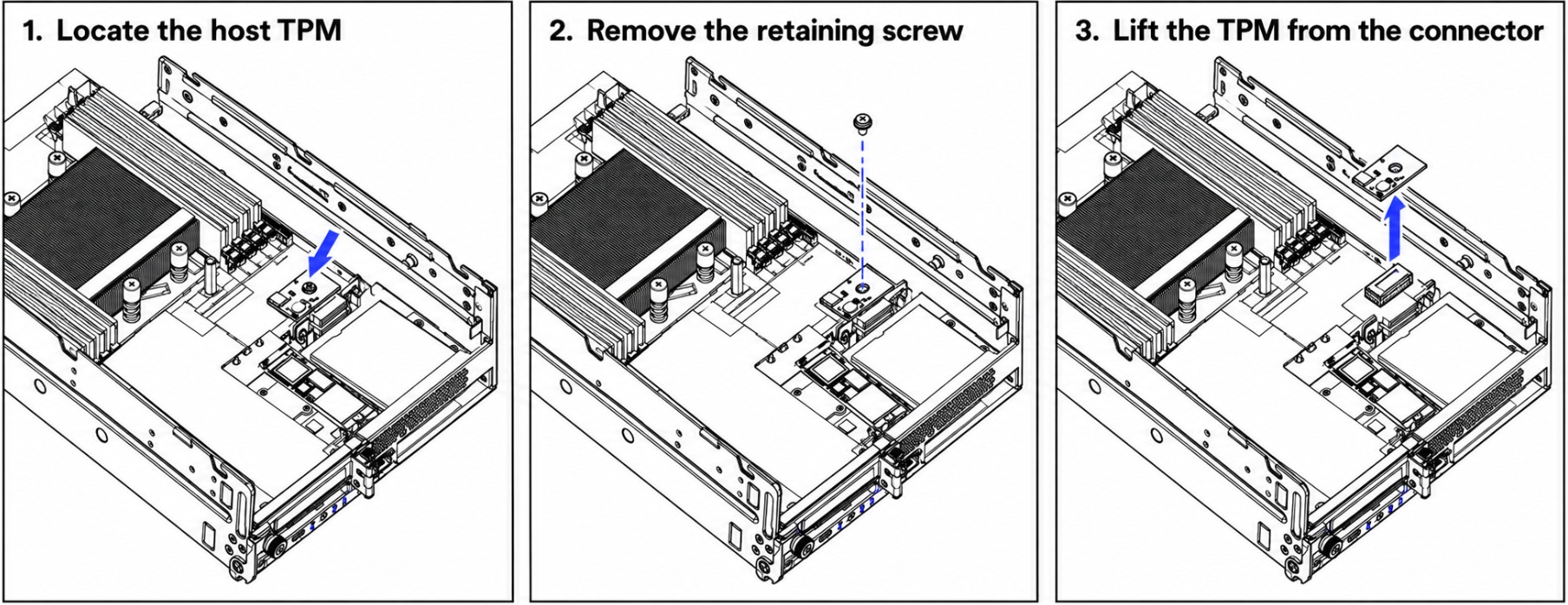
Step 1

Locate the host TPM on the system board.

Step 2

Remove the TPM’s retaining screw.

Step 3

Lift the TPM from its connector.


Caution


Replacing or clearing a TPM can make encrypted data unavailable.


Installing the Trusted Platform Module

Use this task to install the Trusted Platform Module.

Before you begin


Caution


Replacing or clearing a TPM can make encrypted data unavailable.


Procedure


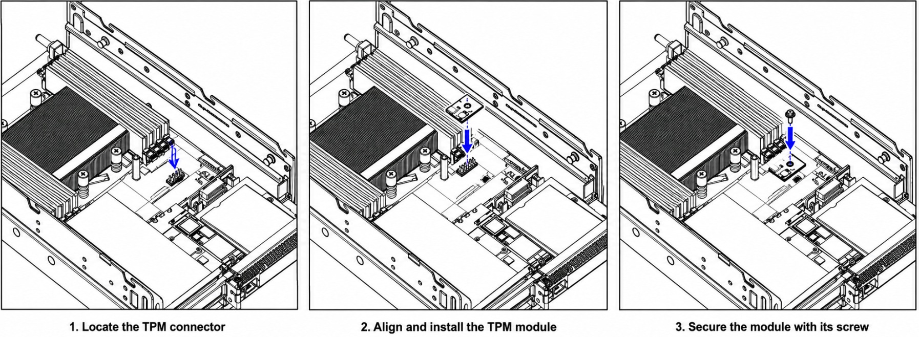
Step 1

Power off the compute node and remove it from the chassis.

Step 2

Remove the top cover and GPU tray module using the approved procedure.

Step 3

Locate the host TPM connector on the system board.

Step 4

Align and install the TPM module.

Step 5

Secure the TPM module with its screw.

Step 6

Reinstall the top cover and compute node.