Recycling Node Components

This chapter contains the following topics:

Recycling the Cisco UCS XE150c Compute Node PCB

The Cisco UCS XE150c Compute Node contains a PCB. To remove the PCB for recycling, you must also remove additional components such as PCIe cards, DIMM modules, the CPU and heatsink.

Use this procedure to recycle the XE150c compute node's PCB.

Before you begin

Gather the following tools:

  • One #1 Phillips (cross-head) screwdriver

  • One #2 Philips (cross-head) screwdriver

  • One #8 hexhead wrench or hex nut driver

Some components on the XE150c compute node have designated touch points where you should grasp the component. Touch points are indicated in these illustrations as a solid blue circle. When indicated, use the touch point. Do not grasp the component at any other locations than the touch point when the touch point is shown.

Procedure


Step 1

Remove the node's top cover. For more information, refer to Removing a Node Top Cover.

Step 2

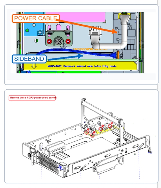
Remove the nodes GPU tray assembly. For more information, refer to Removing GPU tray assembly.

  1. Remove the power cable and sideband cable.

  2. Using #2 Phillips screwdriver, remove 4 screws and remove the power board from the GPU tray.

Step 3

Remove the left PCIe module. For more information, refer to Removing a PCIe Adapter.

Step 4

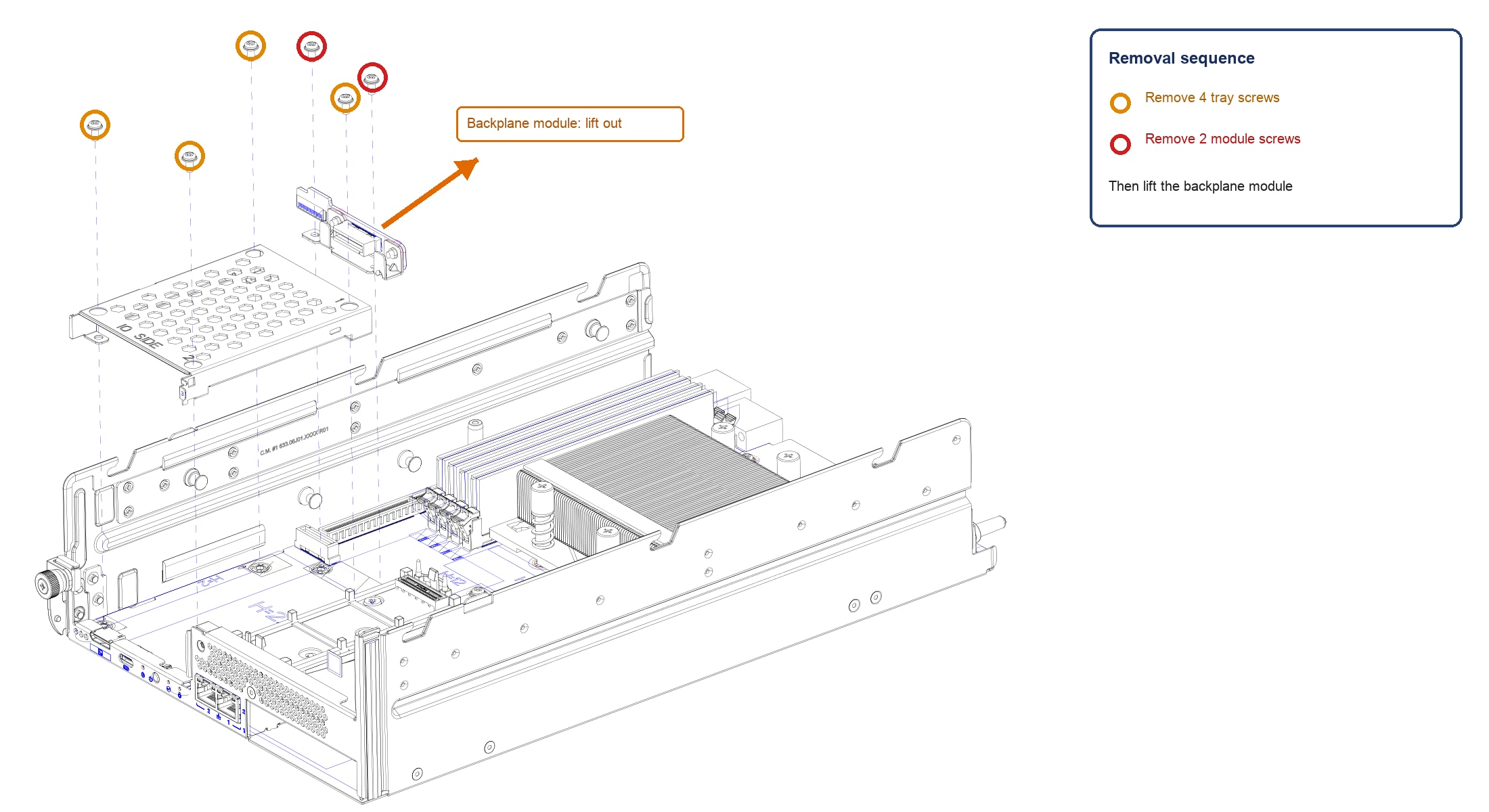
Remove the left E3.S backplane module.

  1. Using a #2 Phillips screwdriver, remove 4 screws to remove the tray. Keep the screw safe if installation is needed later.

  2. Remove 2 screws holding the backplane module and then grasp the module and remove it from the node.

Step 5

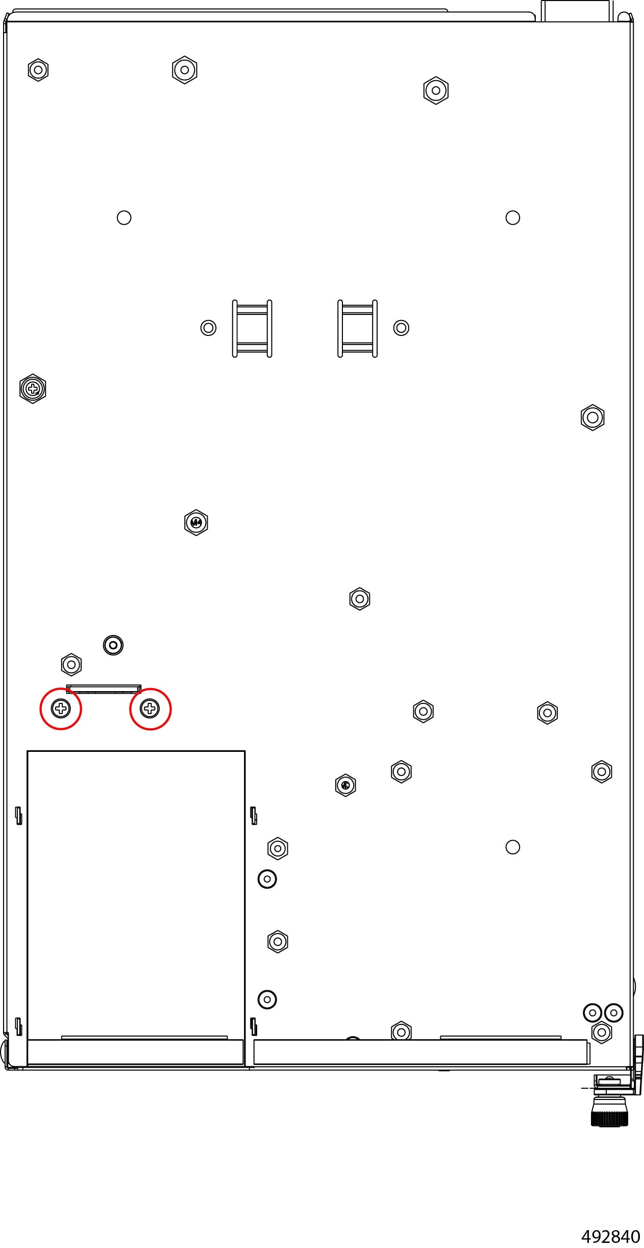
Remove the right E3.S backplane module.

  1. Remove the two backplane module screws.

    Right E3.S backplane module showing the screw locations for removal.

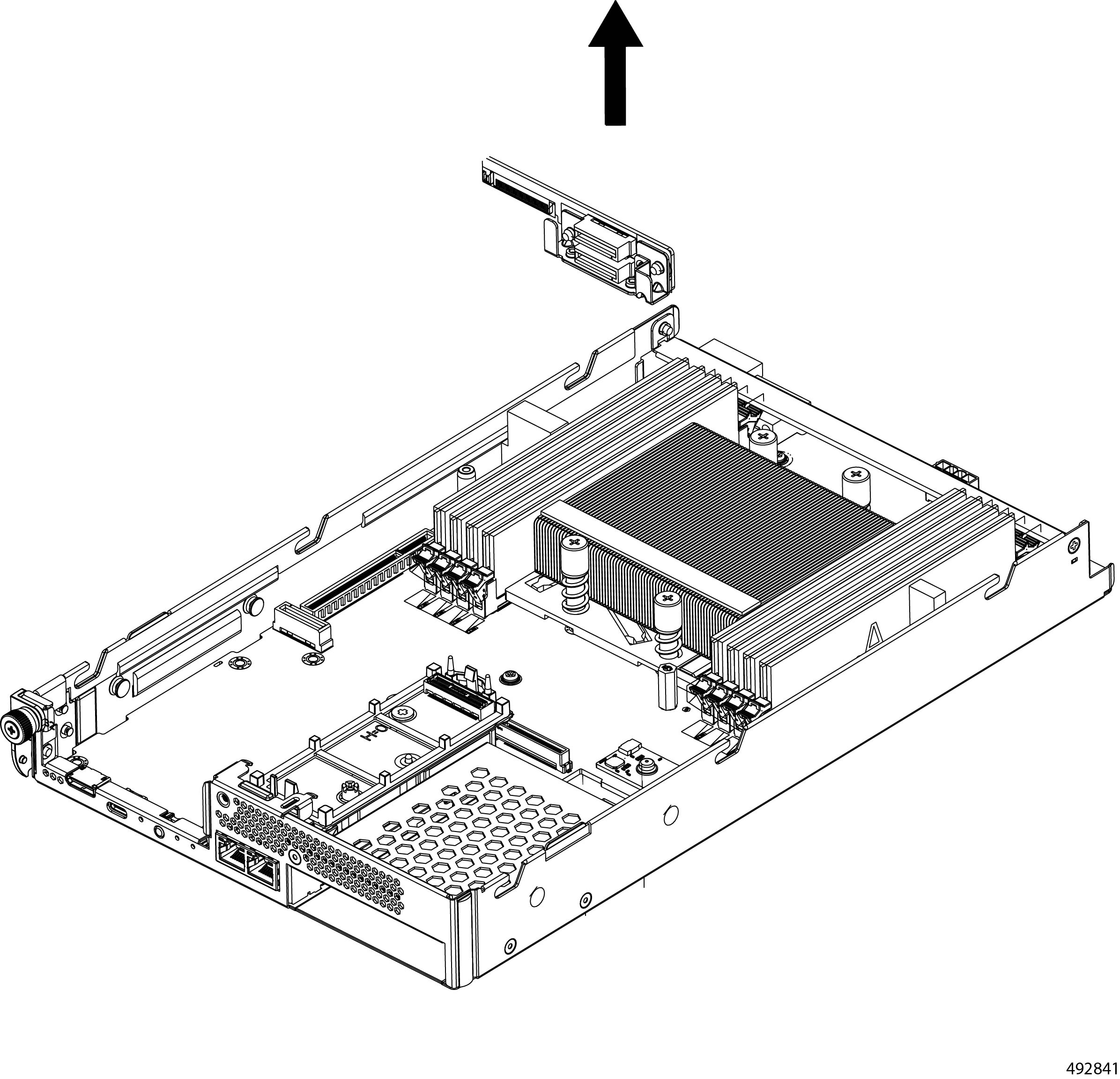
  2. Grasp the backplane module and remove it from the node.

    Right E3.S backplane module being removed from the compute node.

Step 6

Remove the M.2 SSD. For more information, refer to Removing the M.2 SSDs.

Step 7

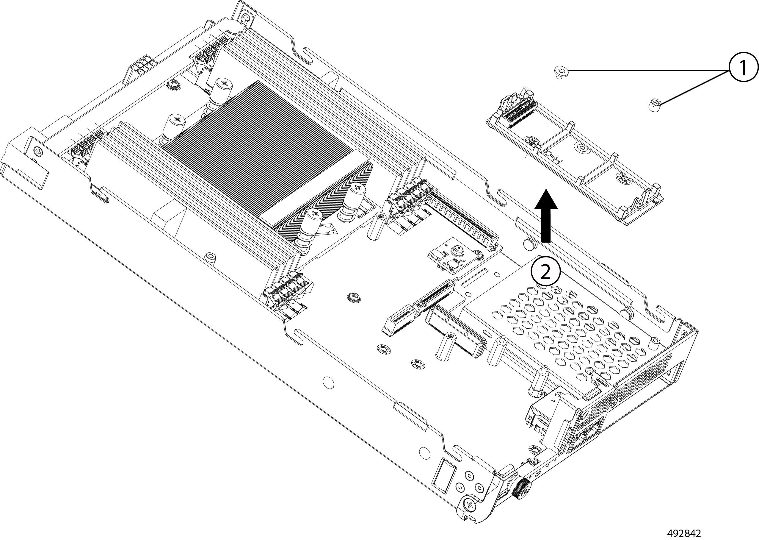
Remove M.2 carrier tray.

  1. Using a #2 Phillips screwdriver, remove the two screws.

  2. Grasp the M.2 carrier tray and remove it from the node.

    M.2 module being removed from the compute node after the retaining screws are removed.

Step 8

Remove the node PCB.

  1. Turn the node over so that the bottom is facing up.

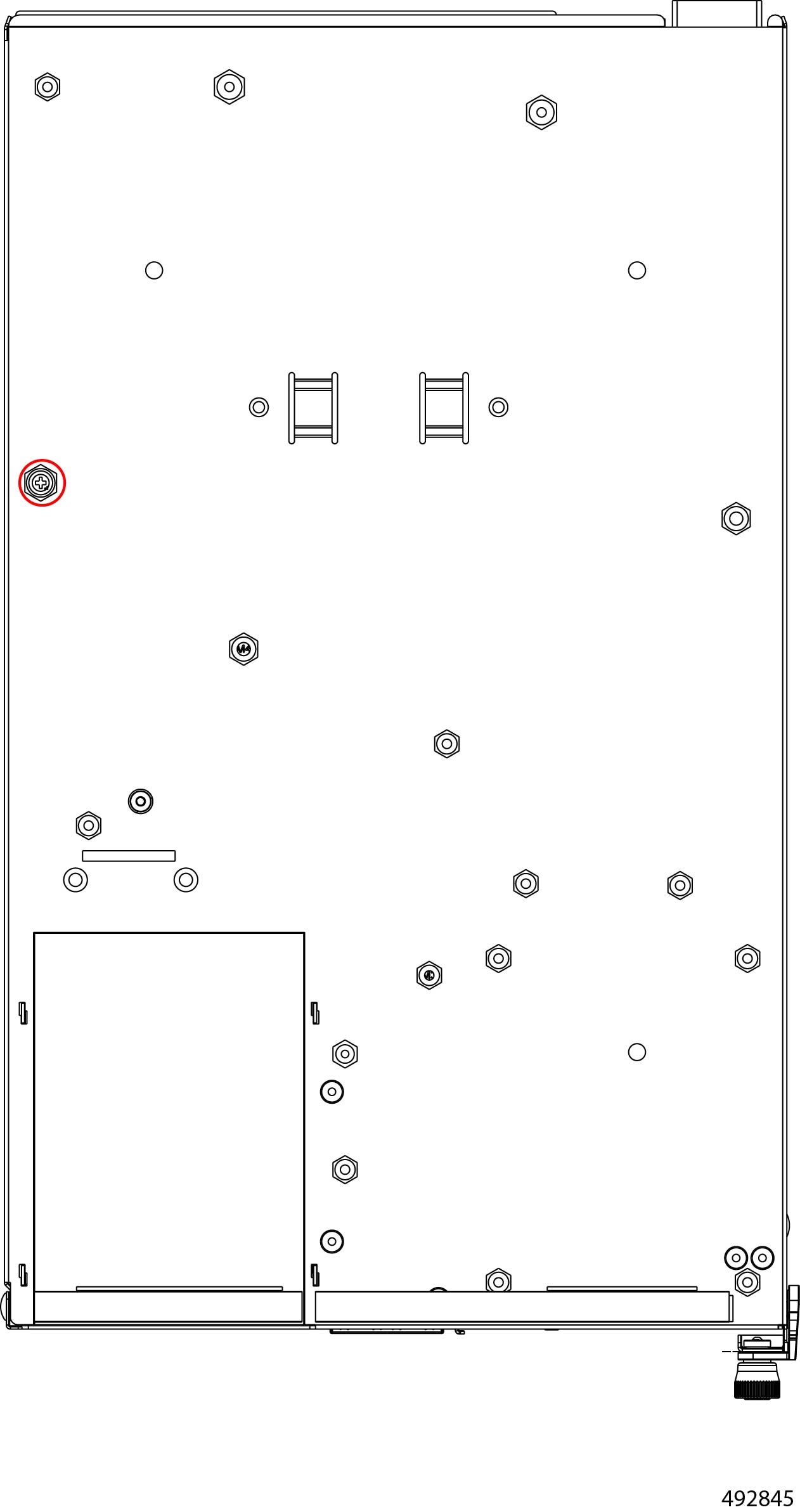
  2. Using a #1 Phillips screwdriver, remove the guide pin screw on the bottom of the node.

    This screw secures a guide pin on the top of the node.

    Bottom of the compute node showing the guide pin screw location.
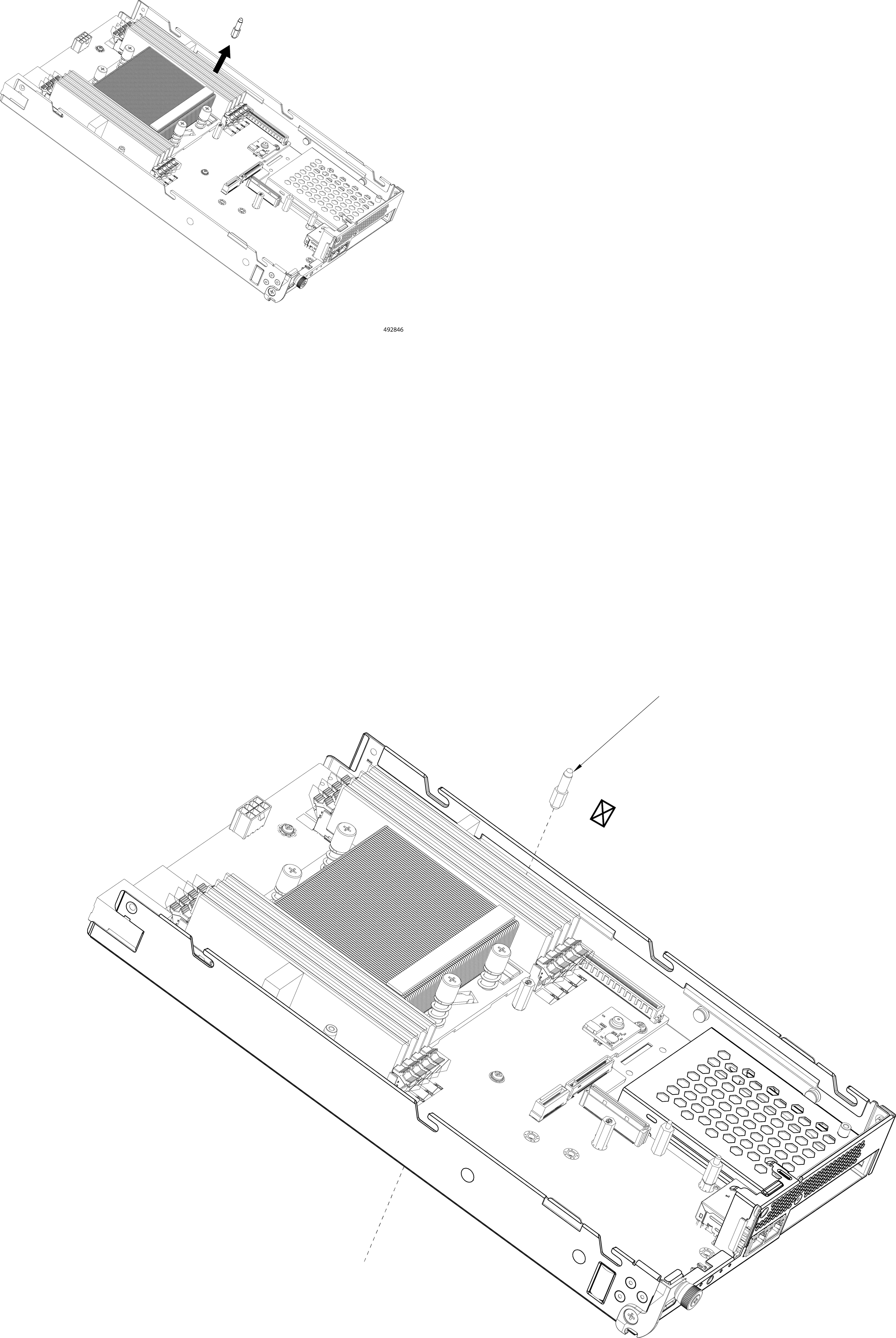
  3. Turn the node over so that the top (component side) is facing up.

  4. Remove the guide pin.

    Guide pin being removed from the top side of the compute node.

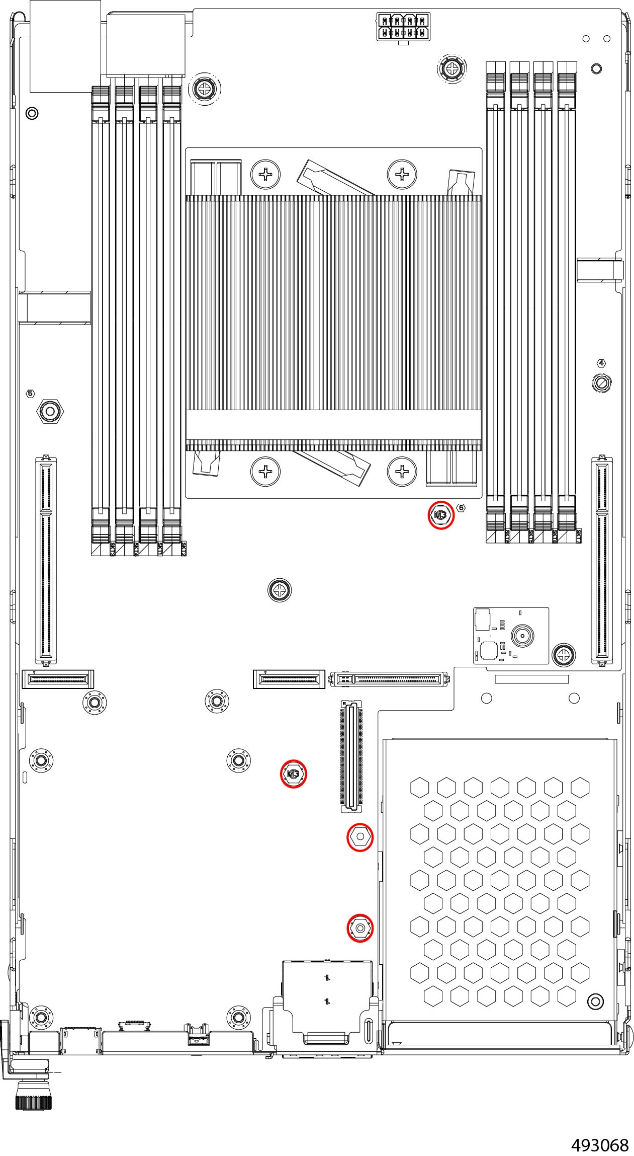
  5. Using a #6 hex nut driver or hexhead wrench, remove the four standoffs.

    Compute node PCB showing the four standoff locations to remove with a #6 hex driver.

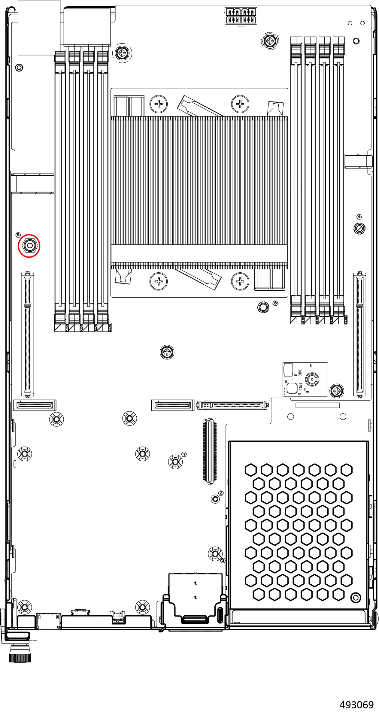
  6. Using a #8 hex nut driver or hexhead wrench, remove the standoff.

    Compute node PCB showing the larger standoff to remove with a #8 hex driver.

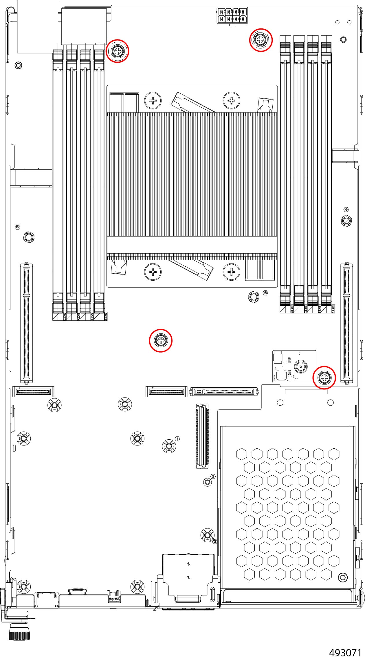
  7. Using a #2 Phillips screwdriver, remove the following four screws.

    Compute node PCB showing four additional screw locations to remove before sliding out the board.

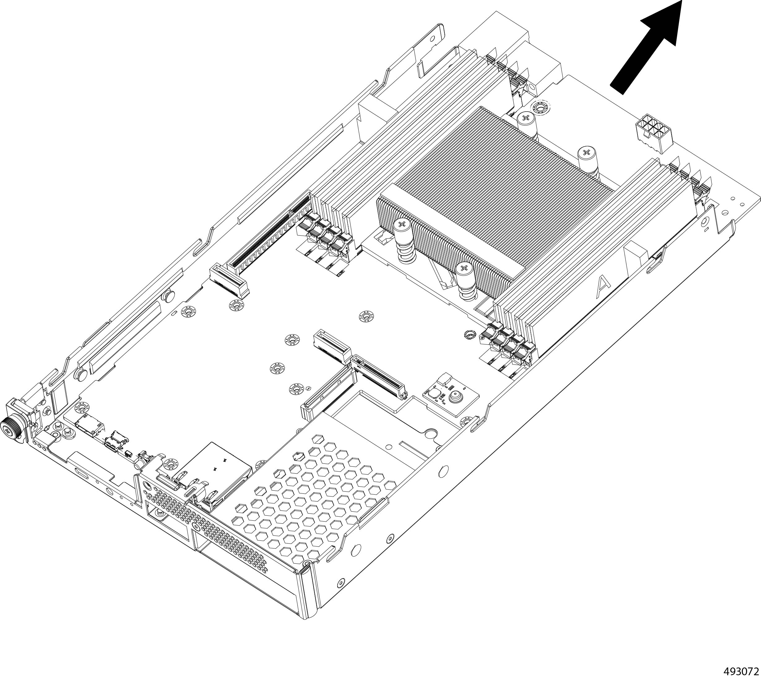
  8. Grasp the node PCB and slide it partially out of the node's sheetmetal tray.

    Compute node PCB partially slid out of the sheetmetal tray after fasteners are removed.

  9. Detach the node's PCB from the sheetmetal tray.

Step 9

Remove the remaining components from the node's PCB.

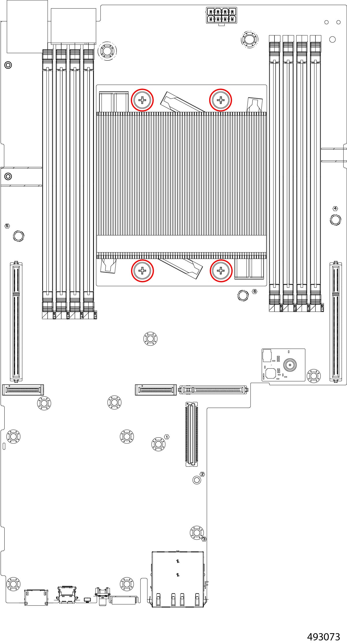
  1. Using a #2 Phillips screwdriver, remove the four standoffs for the heatsink.

    Compute node PCB showing the heatsink standoffs to remove.

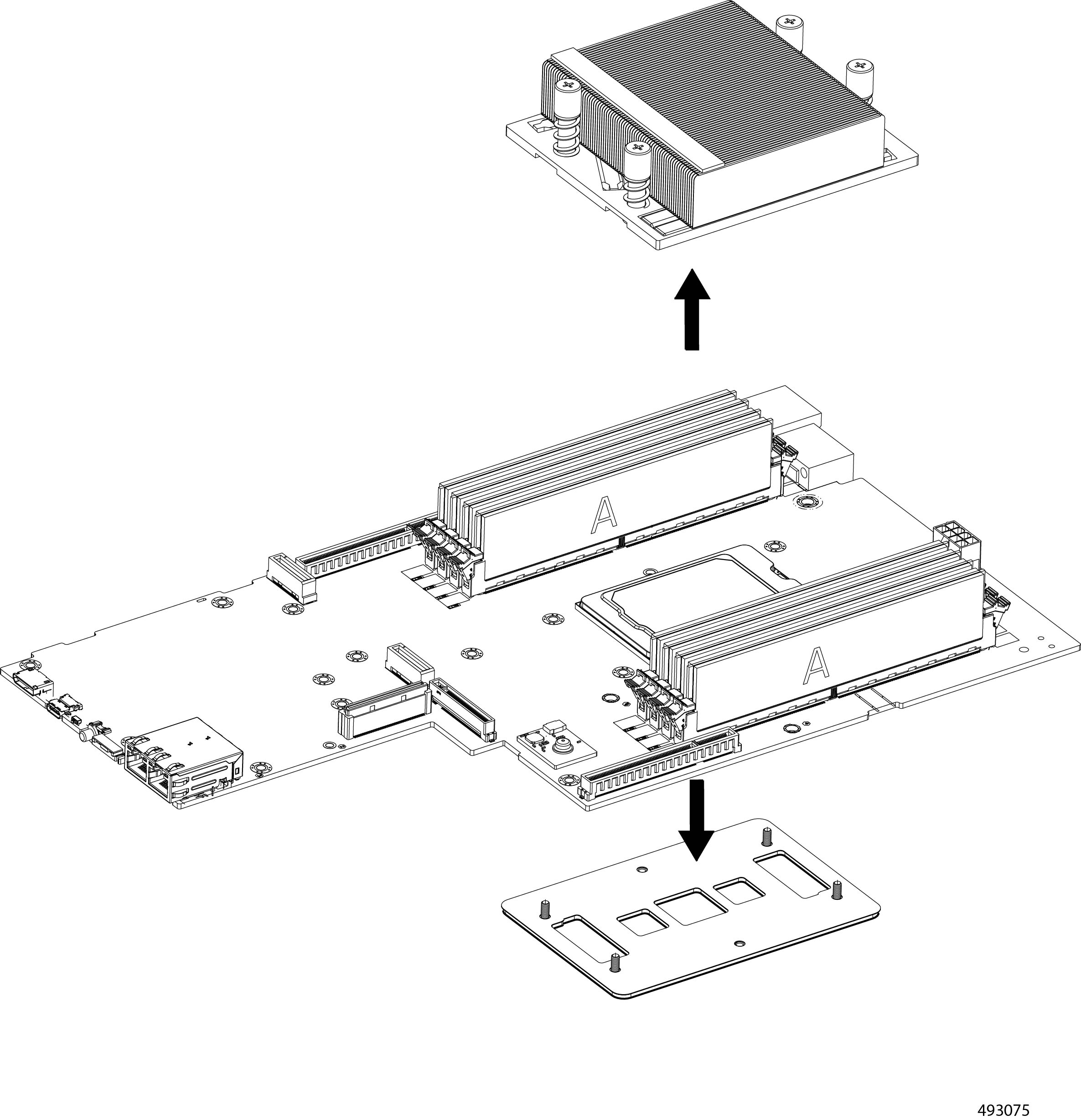
  2. Grasp the heatsink and remove it from the node.

  3. Turn the node over so that the sheetmetal bottom is facing up.

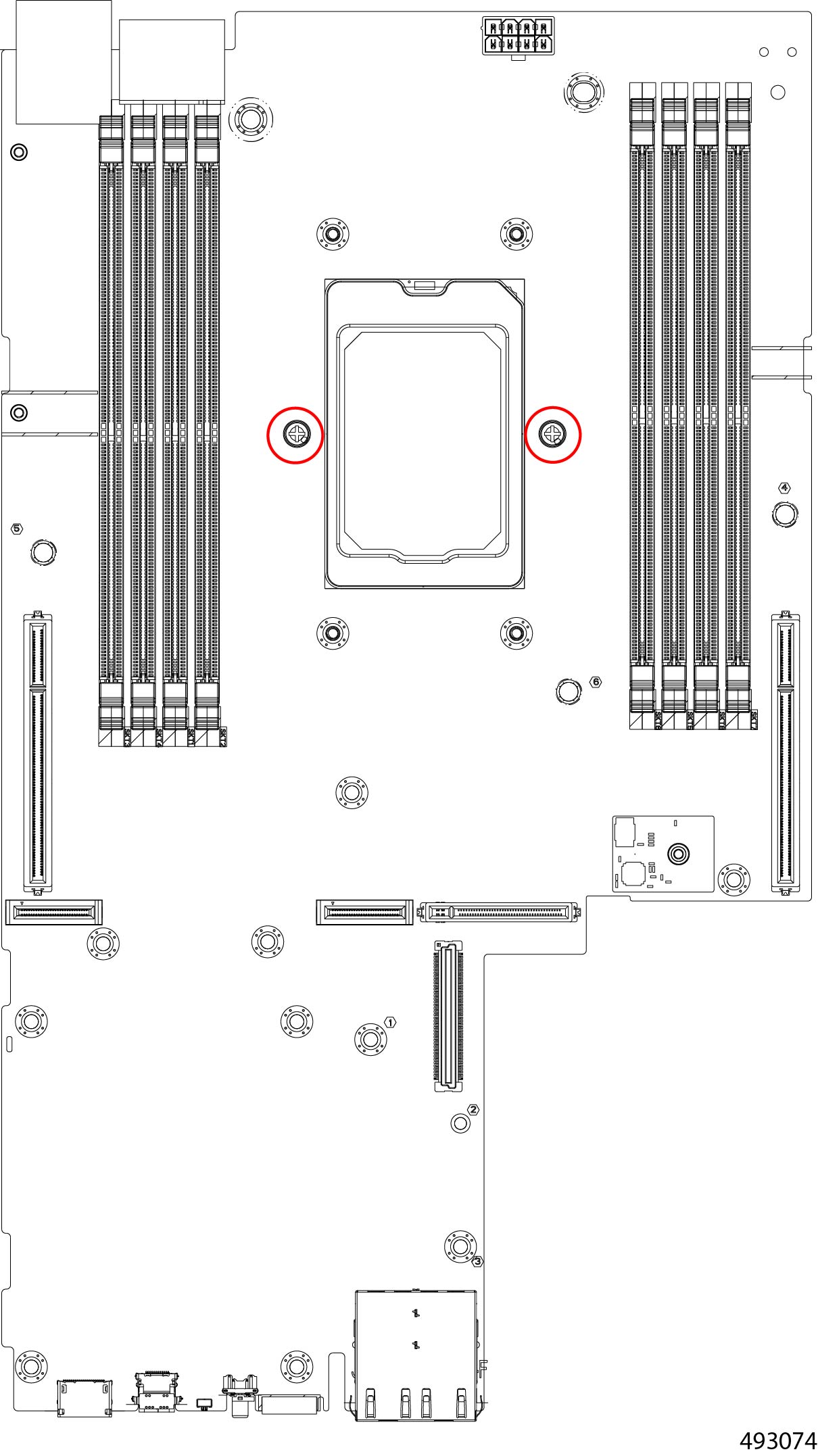
  4. Using a #2 Phillips screwdriver, remove the two backplate screws from the CPU socket.

    Bottom side of the node showing the two CPU socket backplate screws.

  5. Remove the CPU backplate from the node.

    Verify that the both the CPU backplate and heatsink have been removed. Removal of these parts occurs from different sides of the node.

    CPU backplate removed from the node, confirming that both the backplate and heatsink have been taken off.

Step 10

Recycle the DIMM modules.

Step 11

Dispose of the compute node PCB and related components in compliance with your local ewaste and recycling regulations.


Recycling the Compute Node DIMM Modules

DIMM modules must be recycled in compliance with your local ewaste and recycling laws. DIMMs are installed in slots on the compute node and held in place by connector latches.

Use this procedure to recycle DIMM memory modules.

Before you begin

Gather a #2 Phillips screwdriver.

Procedure


Step 1

Remove the compute node. For more information, refer to Removing a Compute Node.

Step 2

Remove the node's top cover. For more information, refer to Removing a Node Top Cover

Step 3

Remove the GPU tray assembly. For more information, refer to Removing GPU tray assembly.

Step 4

Remove the DIMM modules from the node.

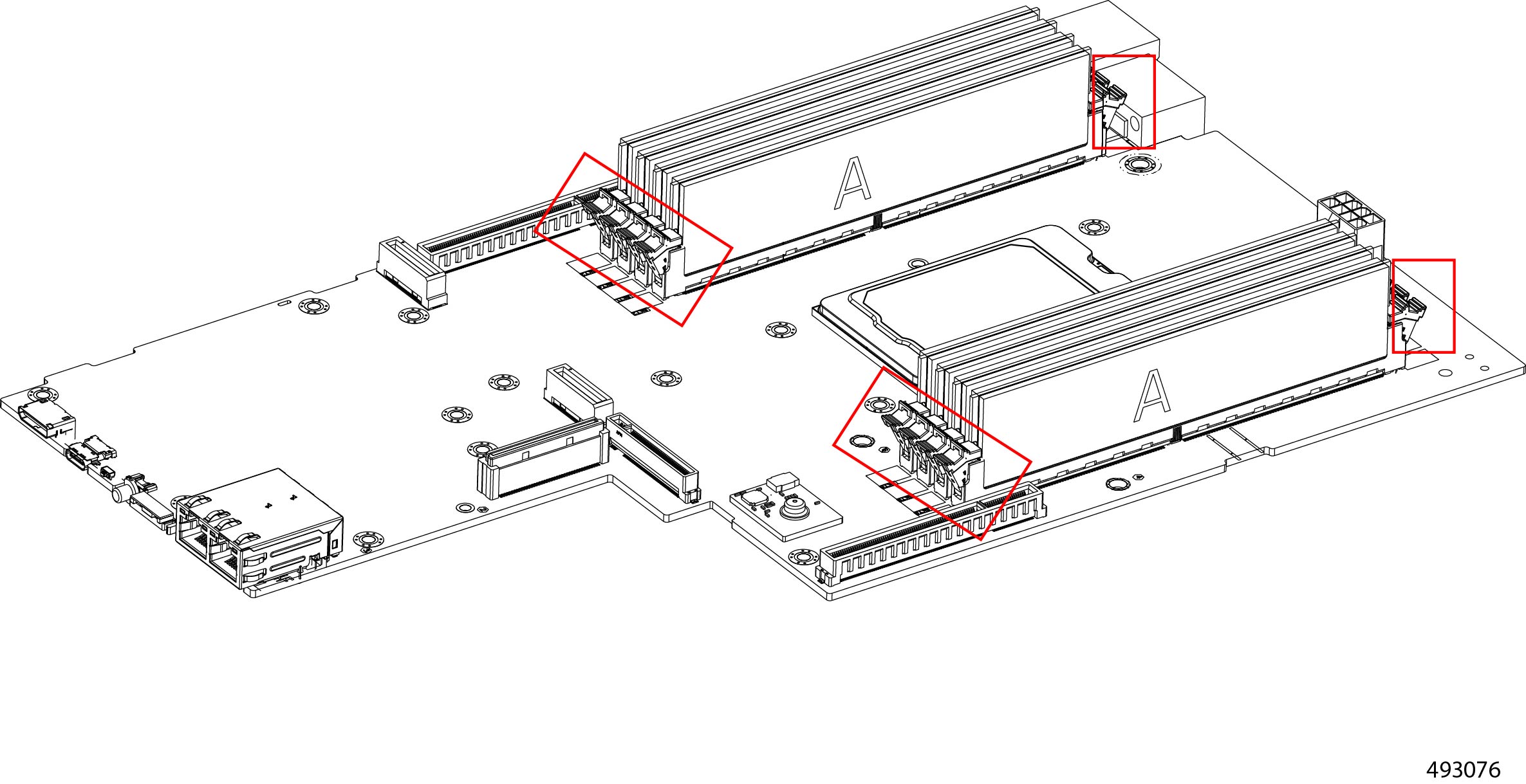
  1. Locate the DIMM modules and their connector latches.

    Compute node interior showing the locations of the DIMM modules and their connector latches on the motherboard.

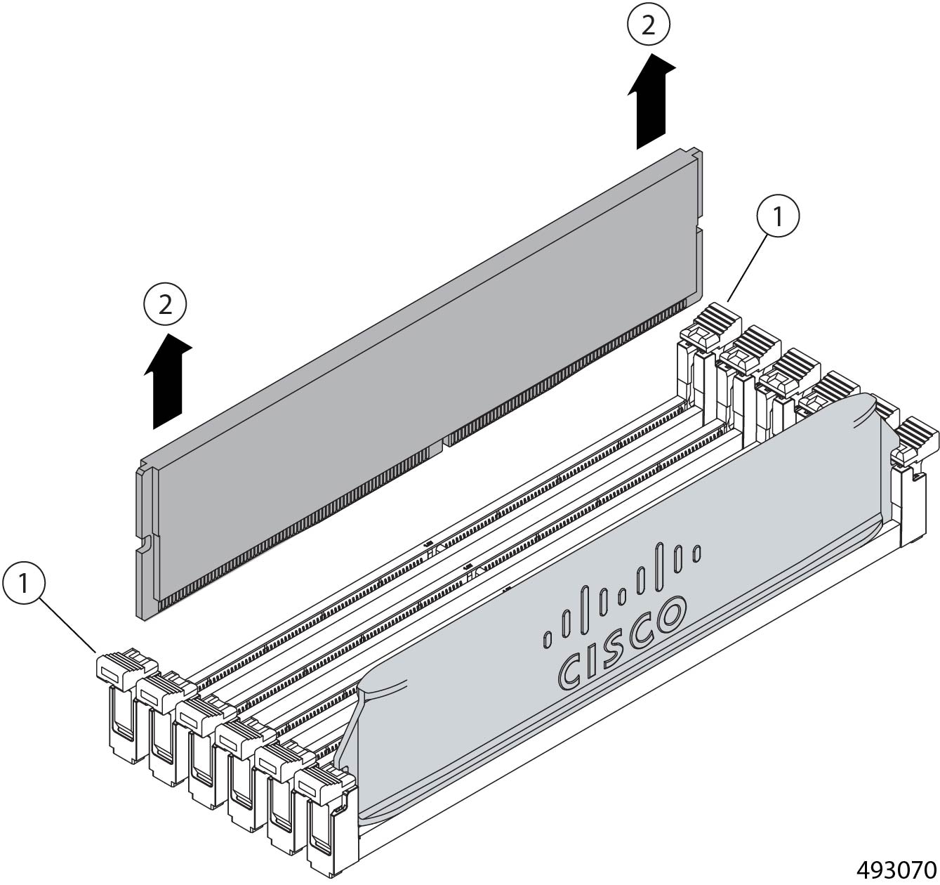
  2. Simultaneously push the connector latch at each end outward (1). This is the open position.

  3. While the connector latch is in the open position, grasp the DIMM module and lift it up to unseat it from its motherboard socket (2) as shown in the following example.

    DIMM module being released by opening both connector latches and lifting the module out of its motherboard socket.

Step 5

Dispose of the DIMMs in compliance with your local regulations for recycling and ewaste.